A Flexible Strain Sensor Based on the Porous Structure of a Carbon Black/Carbon Nanotube Conducting Network for Human Motion Detection

Abstract
1. Introduction
2. Design and Fabrication
2.1. Experimental Materials
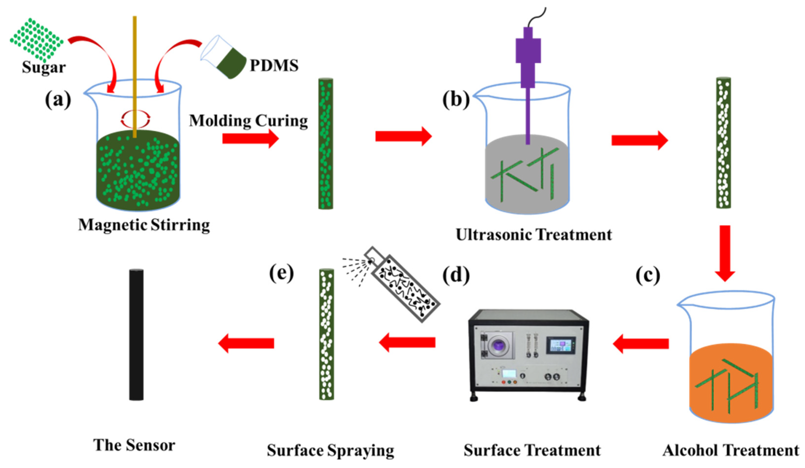
2.2. Fabrication Process of the Porous Flexible Strain Sensor
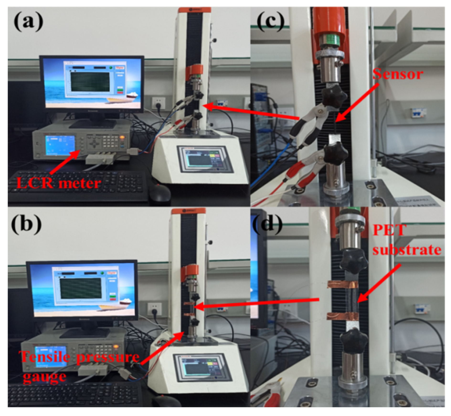
2.3. Characterization and Electrical Measurements
3. Results and Discussion
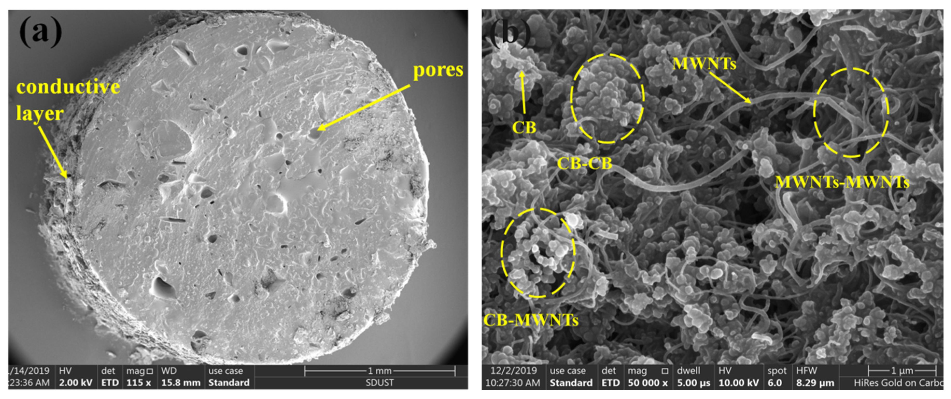
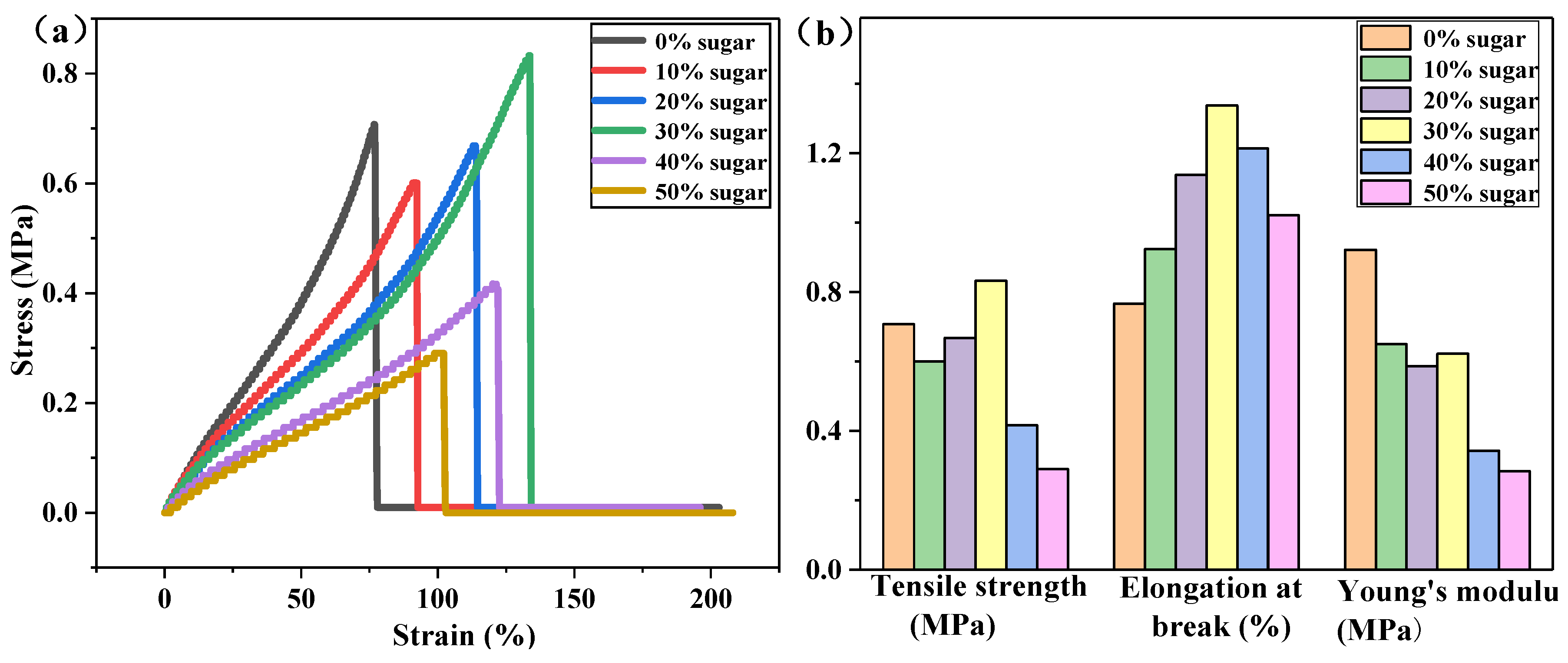
3.1. Characteristics of the Flexible Strain Sensor
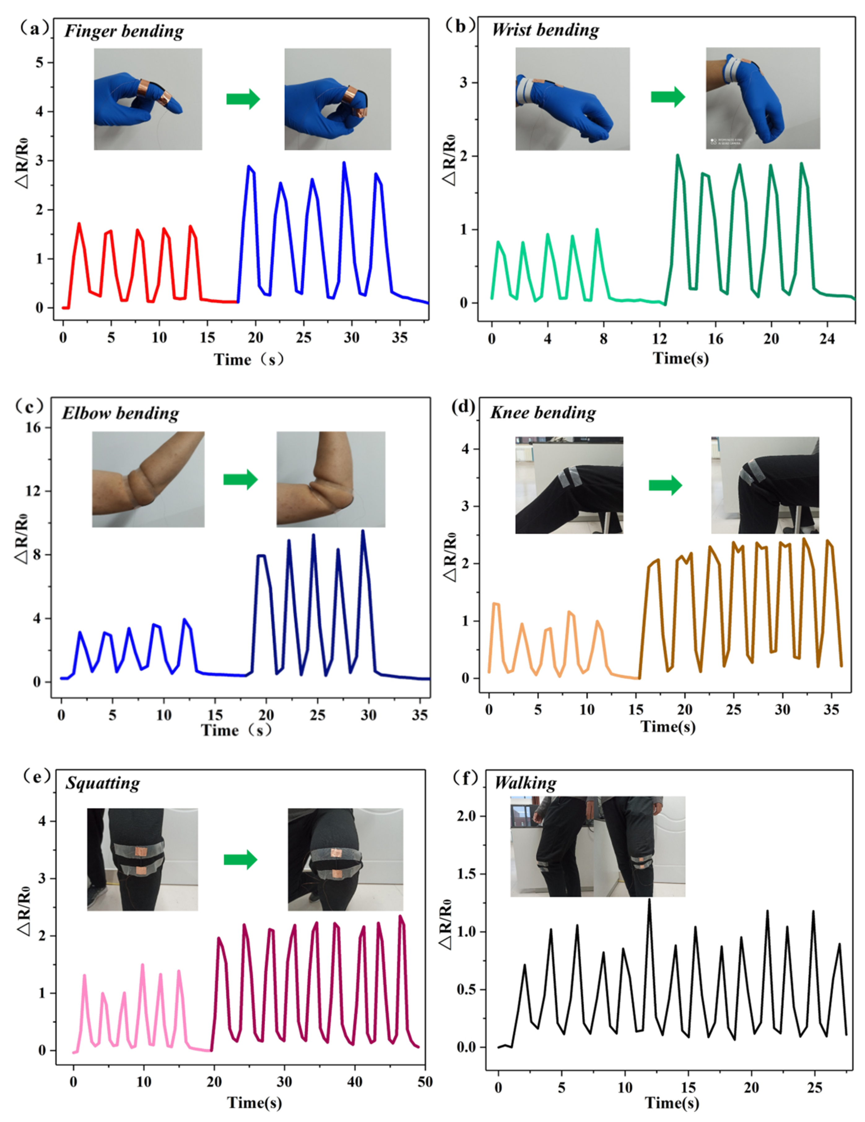
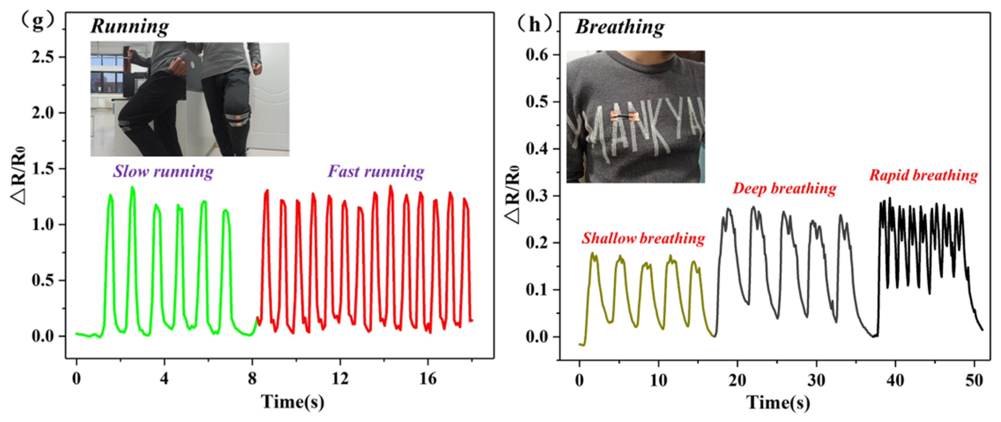
3.2. Application of Strain Sensors as Wearable Strain Sensors for Human Motion Detection
4. Conclusions
Author Contributions
Funding
Conflicts of Interest
References
- Gilshteyn, E.P.; Romanov, S.A.; Kopylova, D.S.; Savostyanov, G.V.; Anisimov, A.S.; Glukhova, O.E.; Nasibulin, A.G. Mechanically Tunable Single-Walled Carbon Nanotube Films as a Universal Material for Transparent and Stretchable Electronics. ACS Appl. Mater. Interfaces 2019, 11, 27327–27334. [Google Scholar] [CrossRef]
- Zheng, X.; Wang, Q.; Luan, J.J.; Li, Y.; Wang, N. Patterned Metal/Polymer Strain Sensor with Good Flexibility, Mechanical Stability and Repeatability for Human Motion Detection. Micromachines 2019, 10, 472. [Google Scholar] [CrossRef]
- Yu, H.; Lian, Y.L.; Sun, T.; Yang, X.N.; Wang, Y.; Xie, G.Z.; Du, X.S.; Gou, J.; Li, W.Z.; Tai, H.L. Two-Sided Topological Architecture on a Monolithic Flexible Substrate for Ultrasensitive Strain Sensors. ACS Appl. Mater. Interfaces 2019, 11, 43543–43552. [Google Scholar] [CrossRef]
- Yan, C.Y.; Wang, J.X.; Kang, W.B.; Cui, M.Q.; Wang, X.; Foo, C.Y.; Chee, K.J.; Lee, P.S. Highly Stretchable Piezoresistive Graphene-Nanocellulose Nanopaper for Strain Sensors. Adv. Mater. 2014, 26, 2022–2027. [Google Scholar] [CrossRef]
- Son, W.; Kim, K.B.; Lee, S.; Hyeon, G.; Hwang, K.G.; Park, W.J. Ecoflex-Passivated Graphene-Yarn Composite for a Highly Conductive and Stretchable Strain Sensor. J. Nanosci. Nanotechnol. 2019, 16, 6690–6695. [Google Scholar] [CrossRef] [PubMed]
- Du, D.H.; Li, P.C.; Ouyang, J.Y. Graphene Coated Nonwoven Fabrics as Wearable Sensors. J. Mater. Chem. C 2016, 4, 3224–3230. [Google Scholar] [CrossRef]
- Ma, Z.H.; Xu, R.; Wang, W.; Yu, D. A wearable, anti-bacterial strain sensor prepared by silver plated cotton/spandex blended fabric for human motion monitoring. Colloids Surf. A 2019, 582, 123918. [Google Scholar] [CrossRef]
- Li, Q.; Li, J.; Tran, D.Q.; Luo, C.Q.; Gao, Y.; Yu, C.J.; Xuan, F.Z. Engineering of carbon nanotube/polydimethylsiloxane nanocomposites with enhanced sensitivity for wearable motion sensors. J. Mater. Chem. C 2017, 5, 11092–11099. [Google Scholar] [CrossRef]
- Roh, E.; Hwang, B.-U.; Kim, D.; Kim, B.-Y.; Lee, N.-E. Stretchable, Transparent, Ultrasensitive, and Patchable Strain Sensor for Human-Machine Interfaces Comprising a Nanohybrid of CarbonNanotubes and Conductive Elastomers. ACS Nano 2015, 9, 6252–6261. [Google Scholar] [CrossRef] [PubMed]
- Lee, C.J.; Park, K.H.; Han, C.J.; Oh, M.S.; You, B.; Kim, Y.-S.; Kim, J.-W. Crack-induced Ag nanowire networks for transparent, stretchable, and highly sensitive strain sensors. Sci. Rep. 2017, 7, 7959. [Google Scholar] [CrossRef] [PubMed]
- Bauer, S.; Bauer-Gogonea, S.; Graz, I.; Kaltenbrunner, M.; Keplinger, C.; Schwödiauer, R. 25th Anniversary Article: A Soft Future: From Robots and Sensor Skin to Energy Harvesters. Adv. Mater. 2014, 26, 149–162. [Google Scholar] [CrossRef] [PubMed]
- Chong, Y.S.; Yeoh, K.H.; Leow, P.L.; Chee, P.S. Piezoresistive strain sensor array using polydimethylsiloxane-based conducting nanocomposites for electronic skin application. SENSOR Rev. 2018, 38, 494–500. [Google Scholar] [CrossRef]
- Trung, T.Q.; Lee, N.E. Flexible and Stretchable Physical Sensor Integrated Platforms for Wearable Human-Activity Monitoring and Personal Healthcare. Adv. Mater. 2016, 28, 4338–4372. [Google Scholar] [CrossRef]
- Yin, F.G.; Lu, H.J.; Pan, H.; Ji, H.J.; Pei, S.; Liu, H.; Huang, J.Y.; Gu, J.H.; Li, M.Y.; Wei, J. Highly Sensitive and Transparent Strain Sensors with an Ordered Array Structure of AgNWs for Wearable Motion and Health Monitoring. Sci. Rep. 2019, 9, 2403. [Google Scholar] [CrossRef] [PubMed]
- Yin, F.; Ye, D.; Zhu, C.; Qiu, L.; Huang, Y.A. Stretchable, Highly Durable Ternary Nanocomposite Strain Sensor for Structural Health Monitoring of Flexible Aircraft. Sensors 2017, 17, 2677. [Google Scholar] [CrossRef] [PubMed]
- Chen, Y.; Wang, L.; Wu, Z.F.; Luo, J.C.; Li, B.; Huang, X.W.; Xue, H.G.; Gao, J.F. Super-hydrophobic, durable and cost-effective carbon black/rubber composites for high performance strain sensors. Compos. Part B Eng. 2019, 17, 107358. [Google Scholar] [CrossRef]
- Liu, Y.W.; Zheng, H.J.; Liu, M.X. High performance strain sensors based on chitosan/carbon black composite sponges. Mater. Des. 2018, 141, 276–285. [Google Scholar] [CrossRef]
- Yamada, T.; Hayamizu, Y.; Yamamoto, Y.; Yoshiki Yomogida, Y.; Ali Izadi-Najafabadi, A.; Futaba, D.N.; Hata, K. A stretchable carbon nanotube strain sensor for human-motion detection. Nat. Nanotechnol. 2011, 6, 296–301. [Google Scholar] [CrossRef]
- Gao, Y.; Fang, X.L.; Tan, J.P.; Lu, T.; Pan, L.K.; Xuan, F.Z. Highly sensitive strain sensors based on fragmentized carbonnanotube/polydimethylsiloxane composites. Nanotechnology 2018, 29, 235501. [Google Scholar] [CrossRef]
- Tian, H.; Shu, Y.; Cui, Y.L.; Mi, W.T.; Yang, Y.; Xie, D.; Ren, T.L. Scalable fabrication of high-performance and flexible graphene strain sensors. Nanoscale. 2014, 6, 699. [Google Scholar] [CrossRef]
- Liu, H.B.; Xiang, H.C.; Wang, Y.; Li, Z.J.; Qian, L.W.; Li, P.; Ma, Y.C.; Zhou, H.W.; Huang, W. A Flexible Multimodal Sensor That Detects Strain, Humidity, Temperature, and Pressure with Carbon Black and Reduced Graphene Oxide Hierarchical Composite on Paper. ACS Appl. Mater. Interfaces 2019, 11, 40613–40619. [Google Scholar] [CrossRef] [PubMed]
- Amjadi, M.; Pichitpajongkit, A.; Lee, S.; Ryu, S.; Park, I. Highly Stretchable and Sensitive Strain Sensor Based on Silver Nanowire-Elastomer Nanocomposite. ACS Nano. 2014, 8, 5154–5163. [Google Scholar] [CrossRef] [PubMed]
- Li, W.; He, Y.; Xu, J.; Wang, W.Y.; Zhu, Z.T.; Liu, H. Preparation of Ag NWs and Ag NWs@PDMS stretchable sensors based on rapid polyol method and semi-dry process. J. Alloys Compd. 2019, 803, 332–340. [Google Scholar] [CrossRef]
- Zheng, Y.J.; Li, Y.L.; Li, Z.Y.; Wang, Y.L.; Dai, K.; Zheng, G.Q.; Liu, C.T.; Shen, C.Y. The effect of filler dimensionality on the electromechanical performance of polydimethylsiloxane based conductive nanocomposites for flexible strain sensors. Compos. Sci. Technol. 2017, 139, 64–73. [Google Scholar] [CrossRef]
- Pei, Z.; Liu, Y.; Zhang, Q.; Zhao, D.; Wang, J.; Yuan, Z.Y.; Zhang, W.D.; Sang, S.B. Highly Sensitive, Stretchable Strain Sensor Based on Ag@COOH-Functionalized CNTs for Stroke and Pronunciation Recognition. Adv. Electron. Mater. 2019, 5, 1900227. [Google Scholar] [CrossRef]
- Sun, H.L.; Dai, K.; Zhai, W.; Zhou, Y.J.; Li, J.W.; Zheng, G.Q.; Li, B.; Liu, C.T.; Shen, C.Y. A Highly Sensitive and Stretchable Yarn Strain Sensor for Human Motion Tracking Utilizing a Wrinkle-Assisted Crack Structure. ACS Appl. Mater. Interfaces 2019, 11, 36052–36062. [Google Scholar] [CrossRef]
- Gao, J.F.; Li, B.; Huang, X.W.; Wang, L.; Lin, L.W.; Wang, H.; Xue, H.G. Electrically conductive and fluorine free superhydrophobic strain sensors based on SiO2/graphene-decorated electrospun nanofibers for human motion monitoring. Chem. Eng. J. 2019, 373, 298–306. [Google Scholar] [CrossRef]
- Guo, X.H.; Huang, Y.; Zhao, Y.N.; Mao, L.D.; Gao, L.; Pan, W.D.; Zhang, Y.G.; Liu, P. Highly stretchable strain sensor based on SWCNTs/CB synergistic conductive network for wearable human-activity monitoring and recognition. Smart Mater. Struct. 2017, 26, 095017. [Google Scholar] [CrossRef]
- Qiu, J.; Guo, X.H.; Chu, R.; Wang, S.L.; Zeng, W.; Qu, L.; Zhao, Y.N.; Yan, F.; Xing, G.Z. Rapid-Response, Low Detection Limit, and High-Sensitivity Capacitive Flexible Tactile Sensor Based on Three-Dimensional Porous Dielectric Layer for Wearable Electronic Skin. ACS Appl. Mater. Interfaces 2019, 11, 40716–40725. [Google Scholar] [CrossRef]
- Yan, T.; Zhou, H.; Niu, H.T.; Shao, H.; Wang, H.X.; Pan, Z.J.; Lin, T. Highly sensitive detection of subtle movement using a flexible strain sensor from helically wrapped carbon yarns. J. Mater. Chem., C 2019, 7, 10049–10058. [Google Scholar] [CrossRef]
- Liu, P.; Pan, W.D.; Liu, Y.; Liu, J.; Xu, W.R.; Guo, X.H.; Liu, C.X.; Zhang, Y.G.; Ge, Y.J.; Huang, Y. Fully flexible strain sensor from core-spun elastic threads with integrated electrode and sensing cell based on conductive nanocomposite. Compos. Sci. Technol. 2018, 159, 42–49. [Google Scholar] [CrossRef]
- Wang, Y.L.; Jia, Y.Y.; Zhou, Y.J.; Wang, Y.; Zheng, G.Q.; Dai, K.; Liu, C.T.; Shen, C.Y. Ultra-stretchable, sensitive and durable strain sensors based on polydopamine encapsulated carbon nanotubes/elastic bands. J. Mater. Chem., C 2018, 6, 8160–8170. [Google Scholar] [CrossRef]
- Zheng, Y.J.; Li, Y.L.; Dai, K.; Wang, Y.; Zheng, G.Q.; Liu, C.T.; Shen, C.Y. A highly stretchable and stable strain sensor based on hybrid carbon nanofillers/polydimethylsiloxane conductive composites for large human motions monitoring. Compos. Sci. Technol. 2018, 156, 276–286. [Google Scholar] [CrossRef]
- Huang, Y.; Hao, C.; Liu, J.; Guo, X.H.; Zhang, Y.Y.; Liu, P.; Liu, C.X.; Zhang, Y.G. Highly stretchable, rapid-response strain sensor based on SWCNTs/CB nanocomposites coated on rubber/latex polymer for human motion tracking. Sensor Rev. 2019, 39, 233–245. [Google Scholar] [CrossRef]
- Wang, L.H.; Ding, T.H.; Wang, P. Influence of carbon black concentration on piezoresistivity for carbon-black-filled silicone rubber composite. Carbon 2009, 47, 3151–3157. [Google Scholar]
- Li, Y.B.; Shang, Y.Y.; He, X.D.; Peng, Q.Y.; Du, S.Y.; Shi, E.Z.; Wu, S.T.; Li, Z.; Li, P.X.; Cao, A.Y. Overtwisted, Resolvable Carbon Nanotube Yarn Entanglement as Strain Sensors and Rotational Actuators. ACS Nano. 2013, 7, 8128–8135. [Google Scholar] [CrossRef]
- Zhang, S.J.; Zhang, H.L.; Yao, G.; Liao, F.Y.; Gao, M.; Huang, Z.L.; Li, K.Y.; Lin, Y. Highly stretchable, sensitive, and flexible strain sensors based on silver nanoparticles/carbon nanotubes composites. J. Alloys Compd. 2015, 652, 48–54. [Google Scholar] [CrossRef]
- Zhang, R.F.; Peng Pan, P.; Dai, Q.L.; Yang, X.P.; Yang, Z.C.; Wei, J.; Liu, J.; Yuan, Q.P. Sensitive and wearable carbon nanotubes/carbon black strain sensors with wide linear ranges for human motion monitoring. J. Mater. Sci. - Mater. Electron. 2018, 29, 5589–5596. [Google Scholar] [CrossRef]


| Reference | Creation Method | Conductive Material | Gauge Factor | Linear Range | Characteristics |
|---|---|---|---|---|---|
| [33] | Solution mixture | CB MWNTS | 0%–100%-0.91 100%–255%-3.25 255%–300%-13.1 | 0%–300% | Insensitivity to small strain, inadequate comfort |
| [38] | Layer-by-layer assembly | CB MWNTS | Maximum to 45.4 | 15%–150% | Conduction synergy inefficiency |
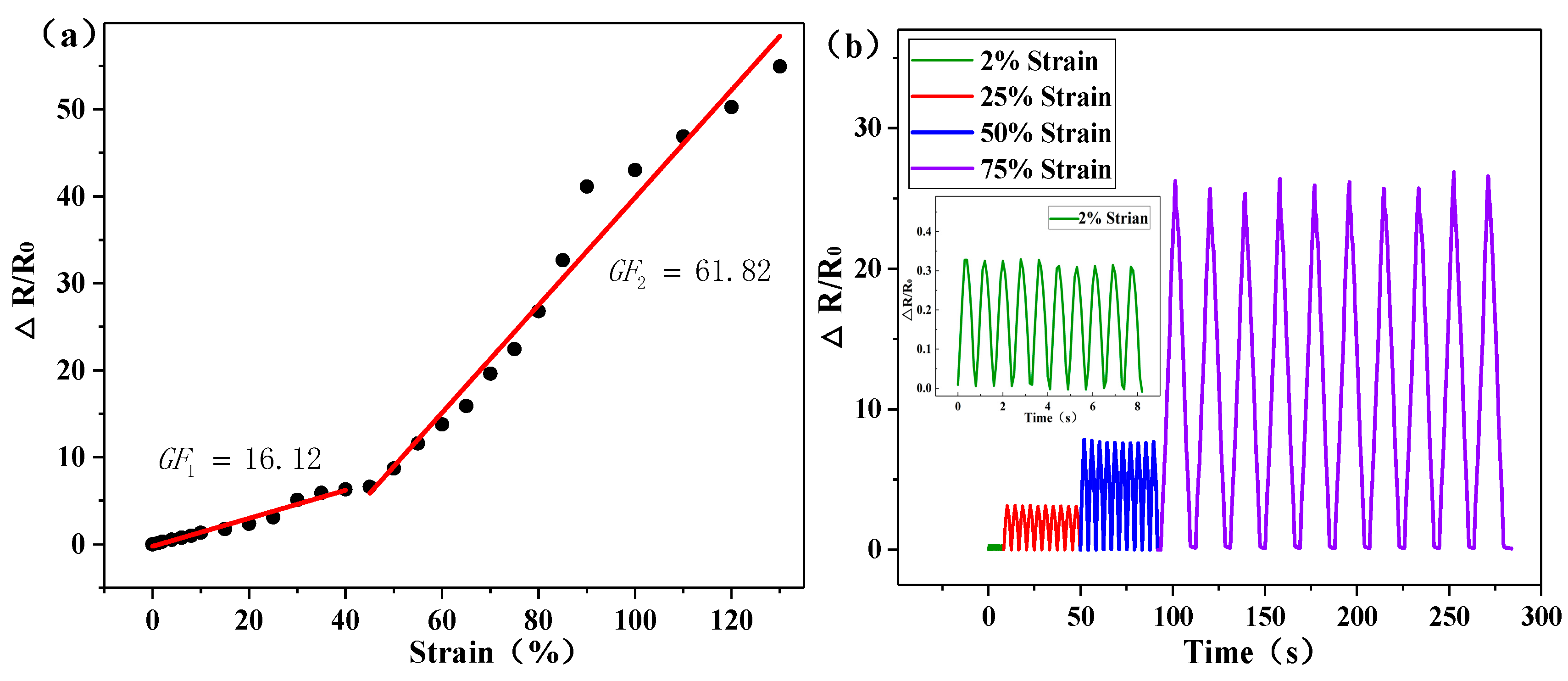
| This work | Spraying | CB MWNTS | 0%–40%-16.12 40%–130%-61.82 | 0%–130% | Sensitivity to small strain, high sensitivity |
© 2020 by the authors. Licensee MDPI, Basel, Switzerland. This article is an open access article distributed under the terms and conditions of the Creative Commons Attribution (CC BY) license (http://creativecommons.org/licenses/by/4.0/).
Share and Cite
Zhang, P.; Chen, Y.; Li, Y.; Zhang, Y.; Zhang, J.; Huang, L. A Flexible Strain Sensor Based on the Porous Structure of a Carbon Black/Carbon Nanotube Conducting Network for Human Motion Detection. Sensors 2020, 20, 1154. https://doi.org/10.3390/s20041154
Zhang P, Chen Y, Li Y, Zhang Y, Zhang J, Huang L. A Flexible Strain Sensor Based on the Porous Structure of a Carbon Black/Carbon Nanotube Conducting Network for Human Motion Detection. Sensors. 2020; 20(4):1154. https://doi.org/10.3390/s20041154
Chicago/Turabian StyleZhang, Peng, Yucheng Chen, Yuxia Li, Yao Zhang, Jian Zhang, and Liangsong Huang. 2020. "A Flexible Strain Sensor Based on the Porous Structure of a Carbon Black/Carbon Nanotube Conducting Network for Human Motion Detection" Sensors 20, no. 4: 1154. https://doi.org/10.3390/s20041154
APA StyleZhang, P., Chen, Y., Li, Y., Zhang, Y., Zhang, J., & Huang, L. (2020). A Flexible Strain Sensor Based on the Porous Structure of a Carbon Black/Carbon Nanotube Conducting Network for Human Motion Detection. Sensors, 20(4), 1154. https://doi.org/10.3390/s20041154