Wideband Beam Steering Concept for Terahertz Time-Domain Spectroscopy: Theoretical Considerations


Abstract
1. Introduction
2. Integrated Optical Ring Resonator-Based ODUs for MLLDs
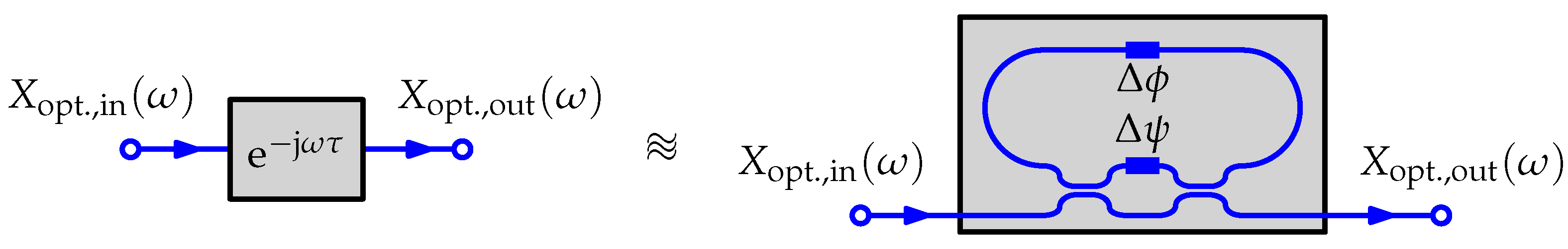
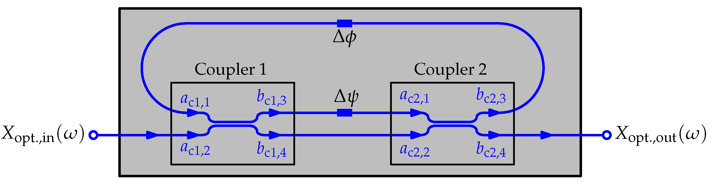
2.1. Mathematical Model of a Mach–Zehnder Modulator-Based ORR
- Attenuation constant .
- Effective refractive index at the wavelength .
- Group index .
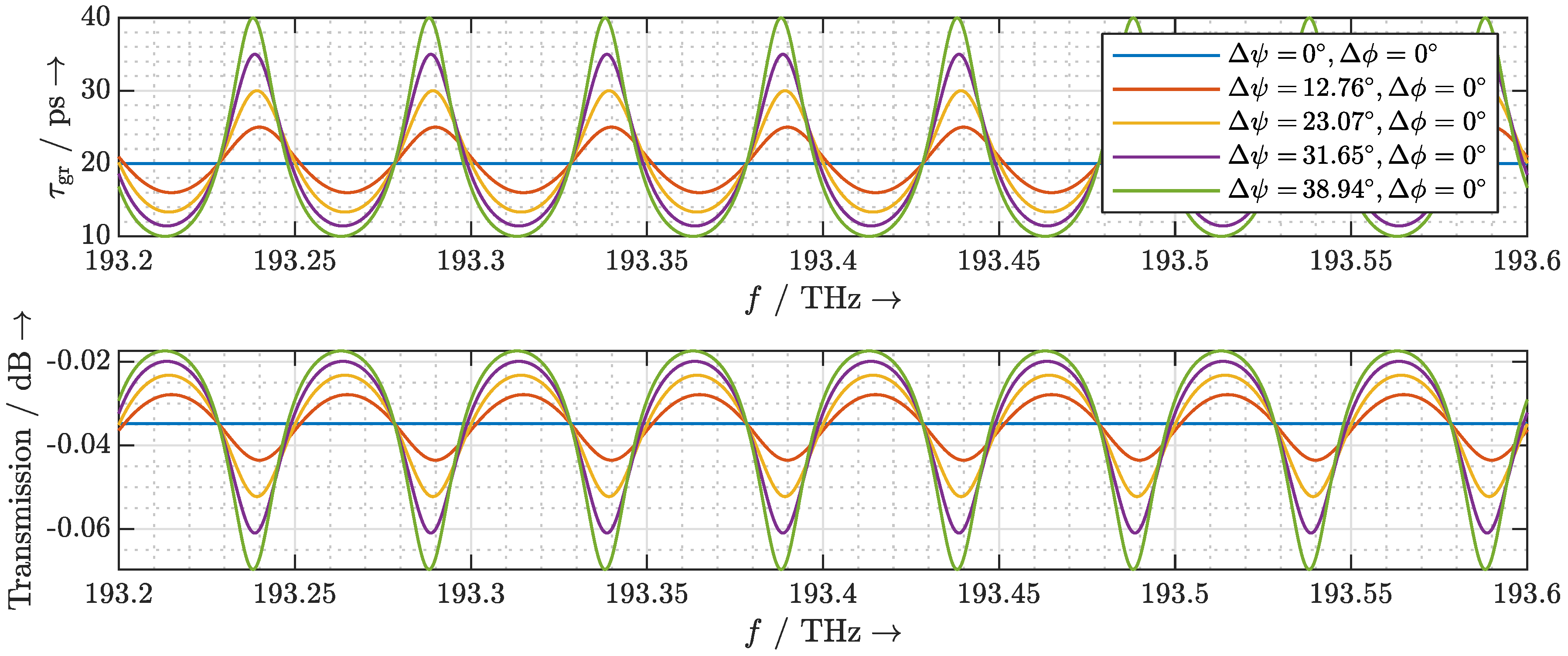
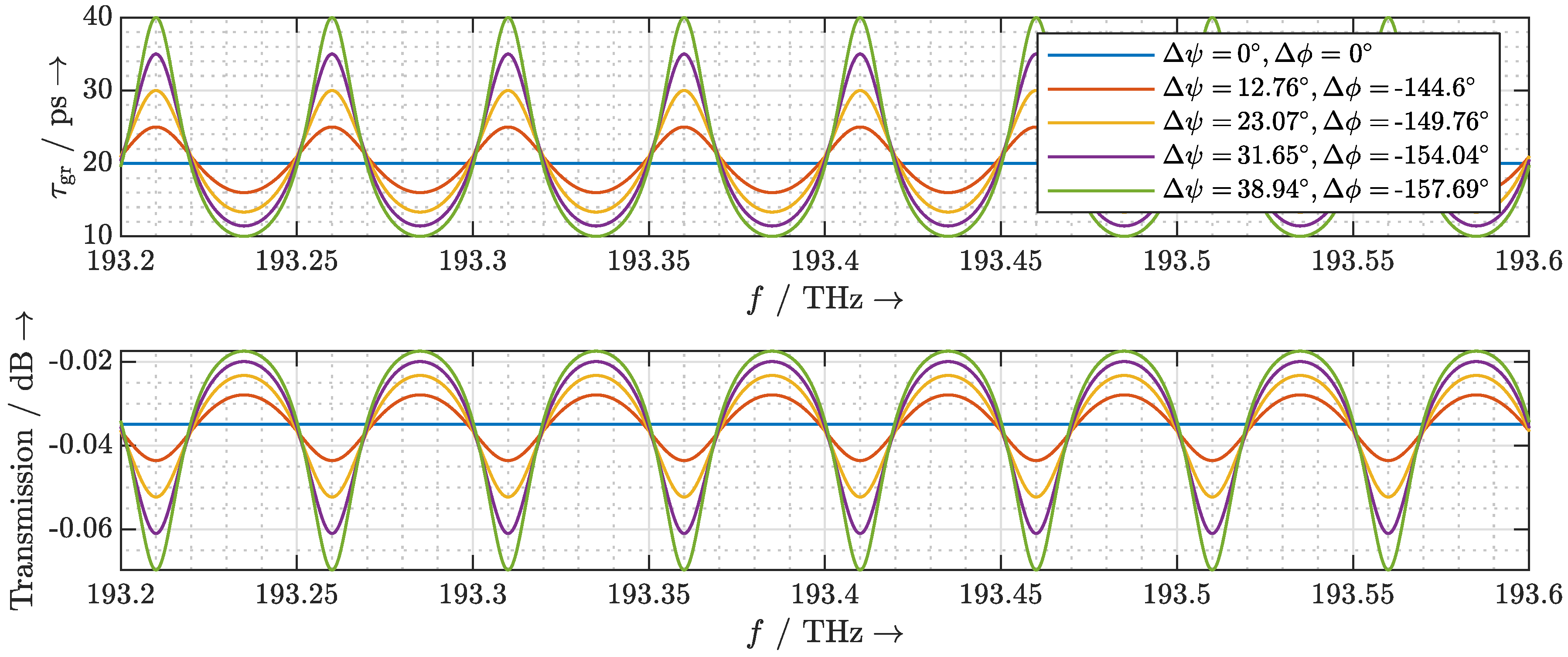
2.2. Dispersion Due to the Phase Shifter
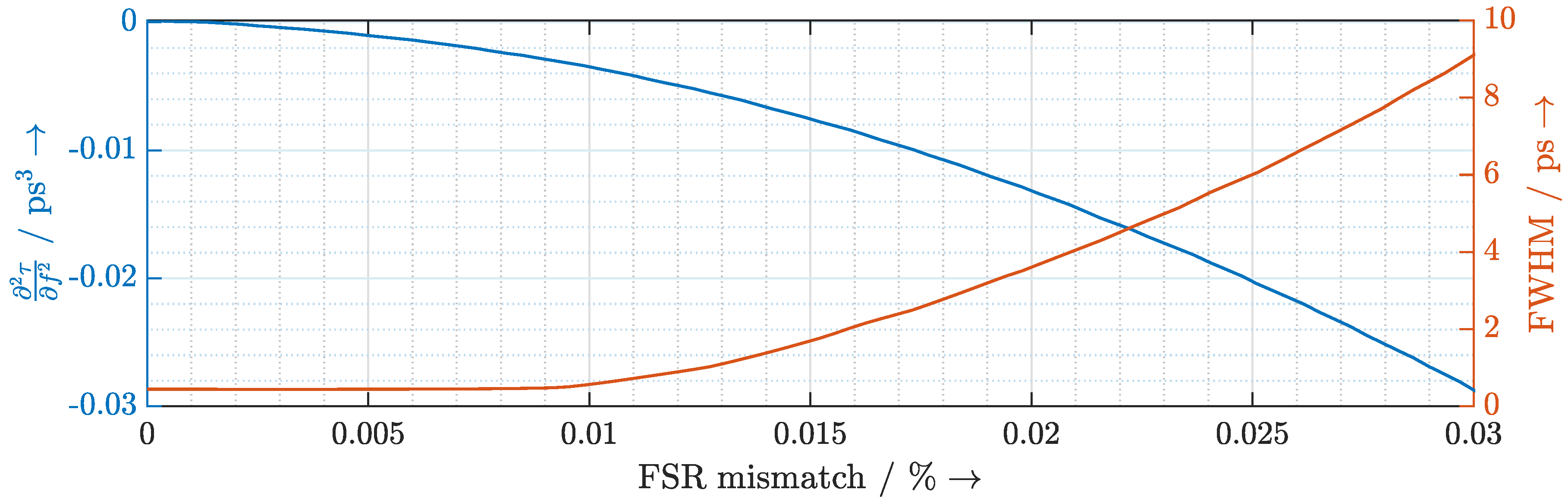
2.3. Dispersion Due to FSR Mismatch
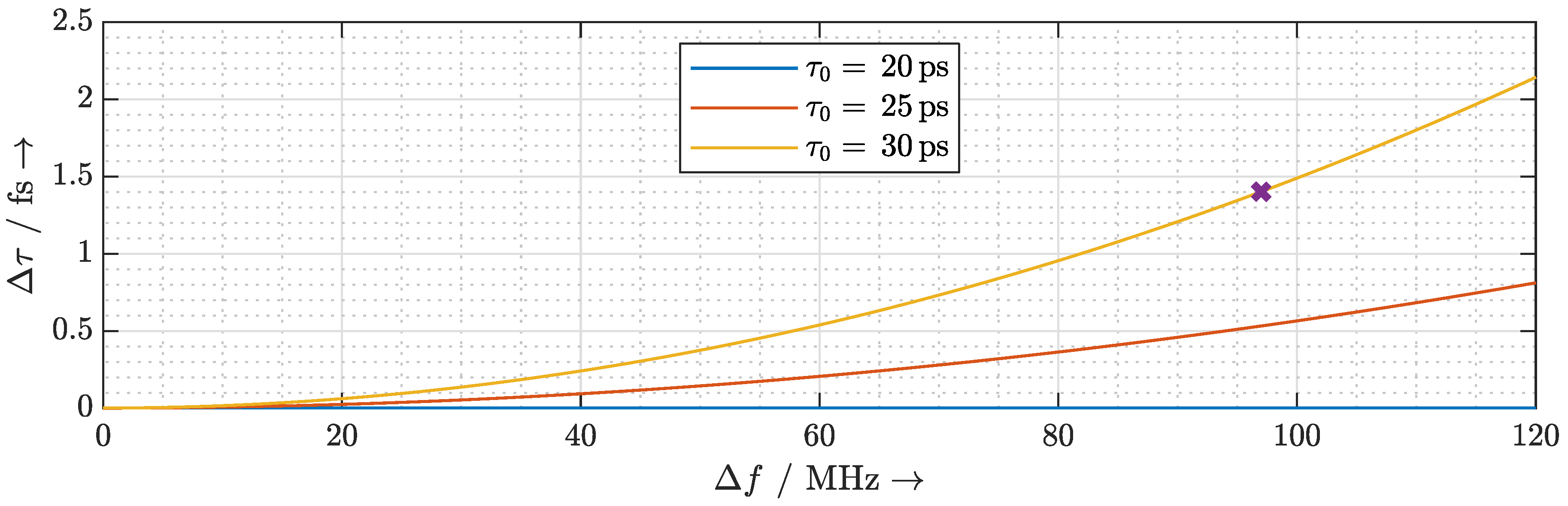
2.4. Delay Fluctuation Due to Frequency Instability
3. Photonic Quasi-True Time Delay Beam Steering for UHRR THz TDS
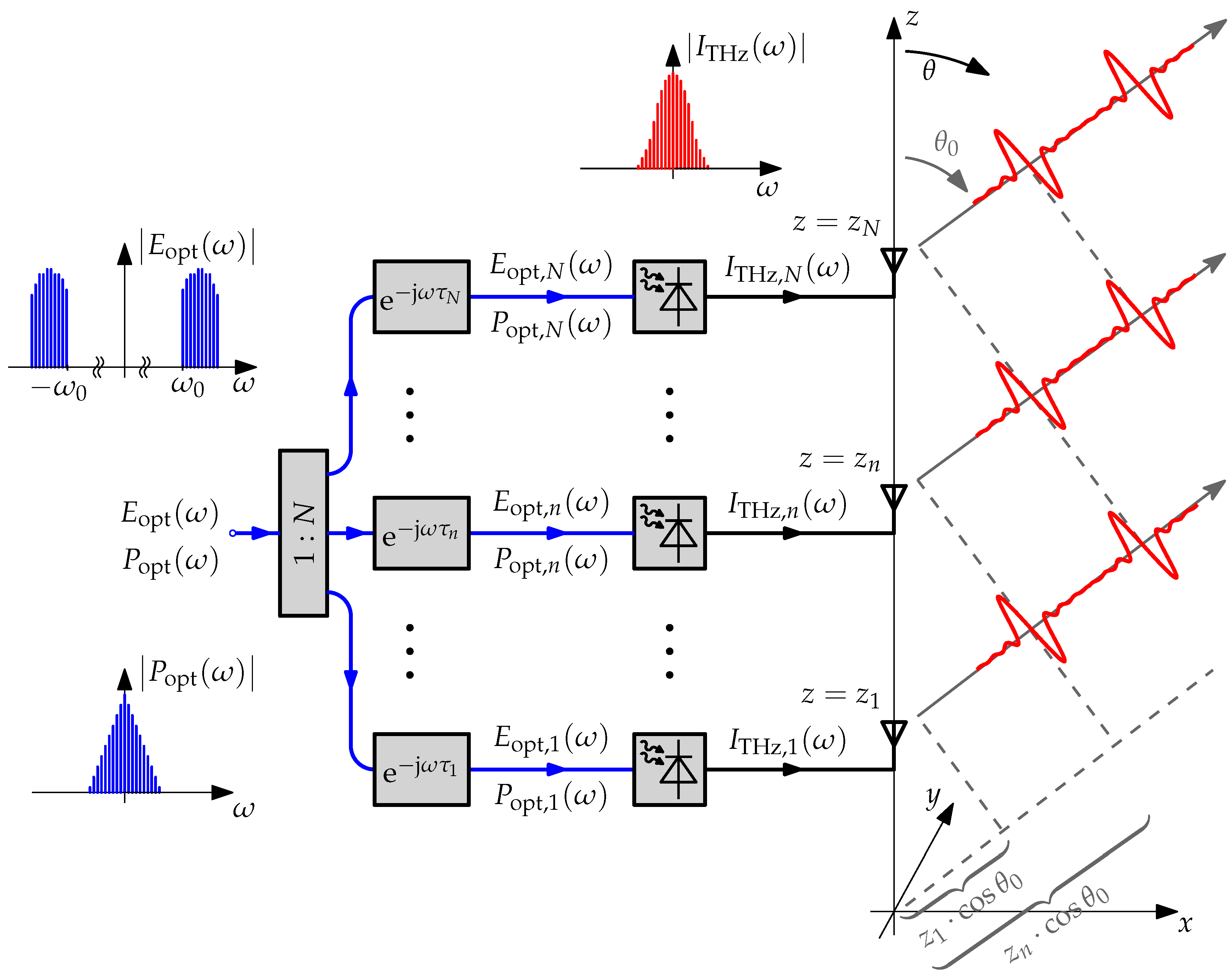
3.1. Design and Operation of the Quasi-True Time Delay Beam Steering Network
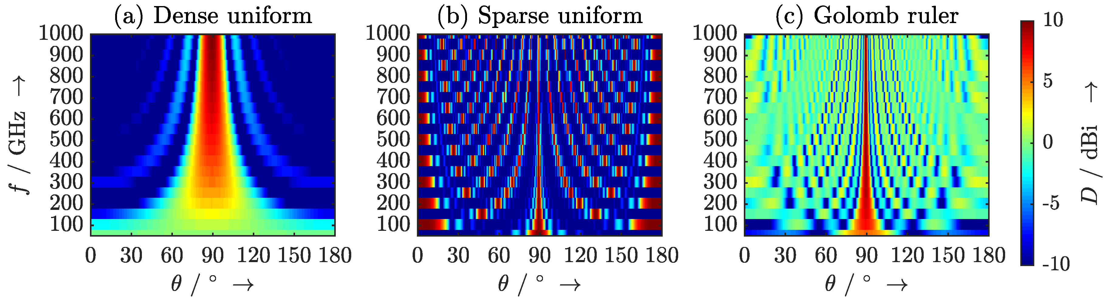
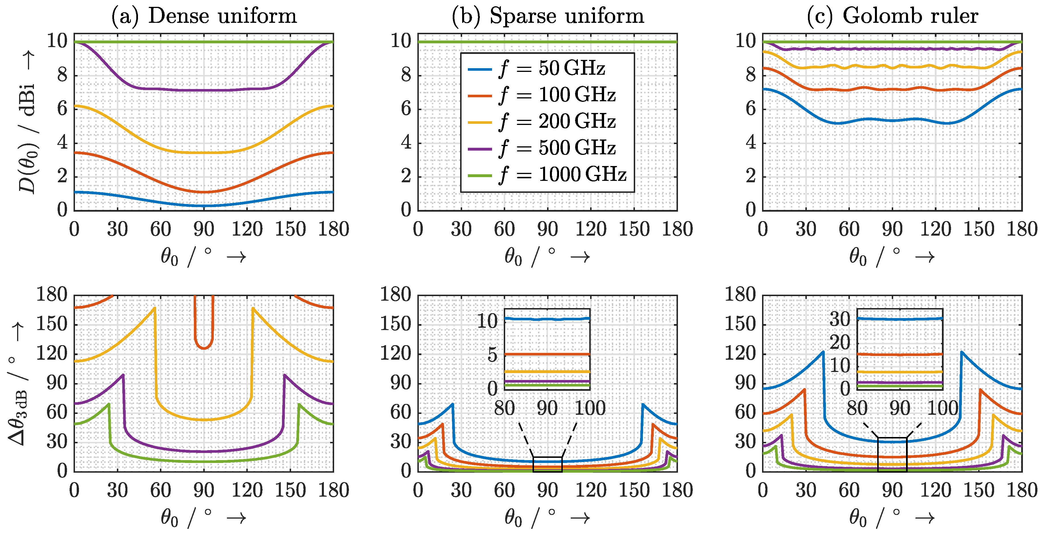
3.2. Design Considerations for the Antenna Array
- The directivity of the main lobe should be as high as possible.
- Side-lobes should be suppressed as much as possible and grating lobes should not occur.
- The beam should be steerable across the entire elevation range .
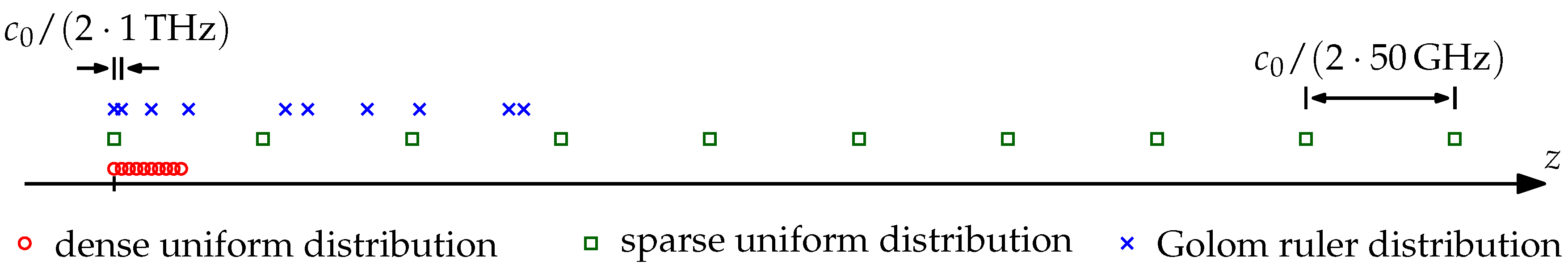
- Dense uniform distribution with with .
- Sparse uniform distribution with with .
- Nonuniform distribution according to a 10-mark Golomb ruler with .
4. Conclusions and Future Perspectives
Author Contributions
Funding
Acknowledgments
Conflicts of Interest
References
- Woolard, D.L.; Brown, R.; Pepper, M.; Kemp, M. Terahertz Frequency Sensing and Imaging: A Time of Reckoning Future Applications? Proc. IEEE 2005, 93, 1722–1743. [Google Scholar] [CrossRef]
- Federici, J.F.; Schulkin, B.; Huang, F.; Gary, D.; Barat, R.; Oliveira, F.; Zimdars, D. THz imaging and sensing for security applications—explosives, weapons and drugs. Semicond. Sci. Technol. 2005, 20, S266–S280. [Google Scholar] [CrossRef]
- Jepsen, P.; Cooke, D.; Koch, M. Terahertz spectroscopy and imaging – Modern techniques and applications. Laser Photonics Rev. 2011, 5, 124–166. [Google Scholar] [CrossRef]
- Naftaly, M.; Vieweg, N.; Deninger, A. Industrial Applications of Terahertz Sensing: State of Play. Sensors 2019, 19, 4203. [Google Scholar] [CrossRef]
- Damyanov, D.; Friederich, B.; Yahyapour, M.; Vieweg, N.; Deninger, A.; Kolpatzeck, K.; Liu, X.; Czylwik, A.; Schultze, T.; Willms, I.; et al. High Resolution Lensless Terahertz Imaging and Ranging. IEEE Access 2019, 7, 147704–147712. [Google Scholar] [CrossRef]
- Mittleman, D.M. Twenty years of terahertz imaging [Invited]. Opt. Express 2018, 26, 9417–9431. [Google Scholar] [CrossRef]
- Sengupta, K.; Hajimiri, A. A 0.28 THz Power-Generation and Beam-Steering Array in CMOS Based on Distributed Active Radiators. IEEE J. Solid-State Circuits 2012, 47, 3013–3031. [Google Scholar] [CrossRef]
- Hillger, P.; Grzyb, J.; Jain, R.; Pfeiffer, U.R. Terahertz Imaging and Sensing Applications With Silicon-Based Technologies. IEEE Trans. Terahertz Sci. Technol. 2019, 9, 1–19. [Google Scholar] [CrossRef]
- Sartorius, B.; Roehle, H.; Künzel, H.; Böttcher, J.; Schlak, M.; Stanze, D.; Venghaus, H.; Schell, M. All-fiber terahertz time-domain spectrometer operating at 1.5 μm telecom wavelengths. Opt. Express 2008, 16, 9565–9570. [Google Scholar] [CrossRef]
- Globisch, B.; Dietz, R.J.B.; Göbel, T.; Schell, M.; Bohmeyer, W.; Müller, R.; Steiger, A. Absolute terahertz power measurement of a time-domain spectroscopy system. Opt. Lett. 2015, 40, 3544–3547. [Google Scholar] [CrossRef]
- Preu, S. A Unified Derivation of the Terahertz Spectra Generated by Photoconductors and Diodes. J. Infrared Millim. Terahertz Waves 2014, 35, 998–1010. [Google Scholar] [CrossRef]
- Chen, Y.; Chen, R.T. A fully packaged true time delay module for a K-band phased array antenna system demonstration. IEEE Photonics Technol. Lett. 2002, 14, 1175–1177. [Google Scholar] [CrossRef]
- Jung, B.; Yao, J. A Two-Dimensional Optical True Time-Delay Beamformer Consisting of a Fiber Bragg Grating Prism and Switch-Based Fiber-Optic Delay Lines. IEEE Photonics Technol. Lett. 2009, 21, 627–629. [Google Scholar] [CrossRef]
- Meijerink, A.; Roeloffzen, C.G.H.; Meijerink, R.; Zhuang, L.; Marpaung, D.A.I.; Bentum, M.J.; Burla, M.; Verpoorte, J.; Jorna, P.; Hulzinga, A.; et al. Novel Ring Resonator-Based Integrated Photonic Beamformer for Broadband Phased Array Receive Antennas—Part I: Design and Performance Analysis. J. Light. Technol. 2010, 28, 3–18. [Google Scholar] [CrossRef]
- Zhuang, L.; Roeloffzen, C.G.H.; Meijerink, A.; Burla, M.; Marpaung, D.A.I.; Leinse, A.; Hoekman, M.; Heideman, R.G.; van Etten, W. Novel Ring Resonator-Based Integrated Photonic Beamformer for Broadband Phased Array Receive Antennas—Part II: Experimental Prototype. J. Light. Technol. 2010, 28, 19–31. [Google Scholar] [CrossRef]
- Liu, Y.; Wichman, A.; Isaac, B.; Kalkavage, J.; Adles, E.J.; Clark, T.R.; Klamkin, J. Tuning Optimization of Ring Resonator Delays for Integrated Optical Beam Forming Networks. J. Light. Technol. 2017, 35, 4954–4960. [Google Scholar] [CrossRef]
- Bauerschmidt, S.; Preu, S.; Malzer, S.; Döhler, G.H.; Wang, L.; Lu, H.; Gossard, A.C. Coherent superposition of terahertz beams from a phased linear photomixer array. In Proceedings of the 2009 International Workshop Terahertz and Mid Infrared Radiation: Basic Research and Practical Applications, Turunc-Marmaris, Turkey, 3 November–6 October 2009; pp. 75–76. [Google Scholar] [CrossRef]
- Preu, S.; Müller-Landau, C.; Malzer, S.; Döhler, G.H.; Lu, H.; Gossard, A.C.; Segovia-Vargas, D.; Rivera-Lavado, A.; Garcia-Muñoz, L.E. Fiber-Coupled 2-D n-i-pn-i-p Superlattice Photomixer Array. IEEE Trans. Antennas Propag. 2017, 65, 3474–3480. [Google Scholar] [CrossRef]
- Merghem, K.; Busch, S.F.; Lelarge, F.; Koch, M.; Ramdane, A.; Balzer, J.C. Terahertz Time-Domain Spectroscopy System Driven by a Monolithic Semiconductor Laser. J. Infrared Millim. Terahertz Waves 2017, 38, 958–962. [Google Scholar] [CrossRef]
- Kolpatzeck, K.; Liu, X.; Tybussek, K.H.; Häring, L.; Zander, M.; Rehbein, W.; Moehrle, M.; Czylwik, A.; Balzer, J.C. System-theoretical modeling of terahertz time-domain spectroscopy with ultra-high repetition rate mode-locked lasers. Opt. Express 2020, 28, 16935–16950. [Google Scholar] [CrossRef]
- Zander, M.; Rehbein, W.; Moehrle, M.; Breuer, S.; Franke, D.; Bimberg, D. InAs/InP QD and InGaAsP/InP QW comb lasers for >1 Tb/s transmission. In Proceedings of the 2019 Compound Semiconductor Week (CSW), Nara, Japan, 19–23 May 2019; p. 1. [Google Scholar] [CrossRef]
- Zander, M.; Rehbein, W.; Moehrle, M.; Breuer, S.; Franke, D.; Schell, M.; Kolpatzeck, K.; Balzer, J.C. High performance BH InAs/InP QD and InGaAsP/InP QW mode-locked lasers as comb and pulse sources. In Optical Fiber Communication Conference (OFC) 2020; Optical Society of America: San Diego, CA, USA, 2020; p. T3C.4. [Google Scholar] [CrossRef]
- Tybussek, K.H.; Kolpatzeck, K.; Faridi, F.; Preu, S.; Balzer, J.C. Terahertz Time-Domain Spectroscopy Based on Commercially Available 1550 nm Fabry–Perot Laser Diode and ErAs:In(Al)GaAs Photoconductors. Appl. Sci. 2019, 9, 2704. [Google Scholar] [CrossRef]
- Dasmahapatra, P.; Stabile, R.; Rohit, A.; Williams, K.A. Optical Crosspoint Matrix Using Broadband Resonant Switches. IEEE J. Sel. Top. Quantum Electron. 2014, 20, 1–10. [Google Scholar] [CrossRef]
- Little, B.E.; Foresi, J.S.; Steinmeyer, G.; Thoen, E.R.; Chu, S.T.; Haus, H.A.; Ippen, E.P.; Kimerling, L.C.; Greene, W. Ultra-compact Si-SiO2 microring resonator optical channel dropping filters. IEEE Photonics Technol. Lett. 1998, 10, 549–551. [Google Scholar] [CrossRef]
- Buckwalter, J.F.; Zheng, X.; Li, G.; Raj, K.; Krishnamoorthy, A.V. A Monolithic 25-Gb/s Transceiver with Photonic Ring Modulators and Ge Detectors in a 130-nm CMOS SOI Process. IEEE J. Solid-State Circuits 2012, 47, 1309–1322. [Google Scholar] [CrossRef]
- Roeloffzen, C.G.H.; Hoekman, M.; Klein, E.J.; Wevers, L.S.; Timens, R.B.; Marchenko, D.; Geskus, D.; Dekker, R.; Alippi, A.; Grootjans, R.; et al. Low-Loss Si3N4 TriPleX Optical Waveguides: Technology and Applications Overview. IEEE J. Sel. Top. Quantum Electron. 2018, 24, 1–21. [Google Scholar] [CrossRef]
- Rosales, R.; Murdoch, S.G.; Watts, R.; Merghem, K.; Martinez, A.; Lelarge, F.; Accard, A.; Barry, L.P.; Ramdane, A. High performance mode locking characteristics of single section quantum dash lasers. Opt. Express 2012, 20, 8649–8657. [Google Scholar] [CrossRef] [PubMed]
- Balanis, C.A. Modern Antenna Handbook; Wiley: Hoboken, NJ, USA, 2008. [Google Scholar]
- Moffet, A. Minimum-redundancy linear arrays. IEEE Trans. Antennas Propag. 1968, 16, 172–175. [Google Scholar] [CrossRef]
- Ishiguro, M. Minimum redundancy linear arrays for a large number of antennas. Radio Sci. 1980, 15, 1163–1170. [Google Scholar] [CrossRef]
- Chambers, C.; Tozer, T.C.; Sharman, K.C.; Durrani, T.S. Temporal and spatial sampling influence on the estimates of superimposed narrowband signals: When less can mean more. IEEE Trans. Signal Process. 1996, 44, 3085–3098. [Google Scholar] [CrossRef]
- King, D.; Packard, R.; Thomas, R. Unequally-spaced, broad-band antenna arrays. IRE Trans. Antennas Propag. 1960, 8, 380–384. [Google Scholar] [CrossRef]


© 2020 by the authors. Licensee MDPI, Basel, Switzerland. This article is an open access article distributed under the terms and conditions of the Creative Commons Attribution (CC BY) license (http://creativecommons.org/licenses/by/4.0/).
Share and Cite
Liu, X.; Kolpatzeck, K.; Häring, L.; Balzer, J.C.; Czylwik, A. Wideband Beam Steering Concept for Terahertz Time-Domain Spectroscopy: Theoretical Considerations. Sensors 2020, 20, 5568. https://doi.org/10.3390/s20195568
Liu X, Kolpatzeck K, Häring L, Balzer JC, Czylwik A. Wideband Beam Steering Concept for Terahertz Time-Domain Spectroscopy: Theoretical Considerations. Sensors. 2020; 20(19):5568. https://doi.org/10.3390/s20195568
Chicago/Turabian StyleLiu, Xuan, Kevin Kolpatzeck, Lars Häring, Jan C. Balzer, and Andreas Czylwik. 2020. "Wideband Beam Steering Concept for Terahertz Time-Domain Spectroscopy: Theoretical Considerations" Sensors 20, no. 19: 5568. https://doi.org/10.3390/s20195568
APA StyleLiu, X., Kolpatzeck, K., Häring, L., Balzer, J. C., & Czylwik, A. (2020). Wideband Beam Steering Concept for Terahertz Time-Domain Spectroscopy: Theoretical Considerations. Sensors, 20(19), 5568. https://doi.org/10.3390/s20195568