
Management of Exciton for Highly-Efficient Hybrid White Organic Light-Emitting Diodes with a Non-Doped Blue Emissive Layer


Abstract

1. Introduction
2. Results and Discussion
3. Conclusions
4. Materials and Methods
4.1. Materials
4.2. Device Fabrication and Measurements
Author Contributions
Funding
Conflicts of Interest
References
- Sun, Y.; Giebink, N.C.; Kanno, H.; Ma, B.; Thompson, M.E.; Forrest, S.R. Management of singlet and triplet excitons for efficient white organic light-emitting devices. Nature 2006, 440, 908. [Google Scholar] [CrossRef] [PubMed]
- Seo, J.H.; Seo, J.H.; Park, J.H.; Kim, Y.K.; Kim, J.H.; Hyung, G.W.; Lee, K.H.; Yoon, S.S. Highly efficient white organic light-emitting diodes using two emitting materials for three primary colors (red, green, and blue). Apply. Phys. Lett. 2007, 90, 203507. [Google Scholar] [CrossRef]
- Liu, X.K.; Chen, Z.; Zheng, C.J.; Chen, M.; Liu, W.; Zhang, X.H.; Lee, C.S. Nearly 100% Triplet Harvesting in Conventional Fluorescent Dopant-Based Organic Light-Emitting Devices Through Energy Transfer from Exciplex. Adv. Mater. 2015, 27, 2025–2030. [Google Scholar] [CrossRef] [PubMed]
- Lu, C.Y.; Jiao, M.; Lee, W.K.; Chen, C.Y.; Tsai, W.L.; Lin, C.Y.; Wu, C.C. Achieving Above 60% External Quantum Efficiency in Organic Light-Emitting Devices Using ITO-Free Low-Index Transparent Electrode and Emitters with Preferential Horizontal Emitting Dipoles. Adv. Funct. Mater. 2016, 26, 3250–3258. [Google Scholar] [CrossRef]
- Zhang, D.; Cai, M.; Zhang, Y.; Zhang, D.; Duan, L. Highly efficient simplified single-emitting-layer hybrid WOLEDs with low roll-off and good color stability through enhanced Forster energy transfer. ACS. Appl. Mater. Inter. 2015, 7, 28693–28700. [Google Scholar] [CrossRef]
- Arsenyan, P.; Petrenko, A.; Leitonas, K.; Volyniuk, D.; Simokaitiene, J.; Klinavicius, T.; Skuodis, E.; Lee, J.-H.; Grazulevicius, J.V. Synthesis and Performance in OLEDs of Selenium-Containing Phosphorescent Emitters with Red Emission Color Deeper Than the Corresponding NTSC Standard. Lnorg. Chem. 2019, 58, 10174–10183. [Google Scholar] [CrossRef]
- Cherpak, V.; Stakhira, P.; Minaev, B.; Baryshnikov, G.; Stromylo, E.; Helzhynskyy, I.; Chapran, M.; Volyniuk, D.; Hotra, Z.; Dabuliene, A. Mixing of phosphorescent and exciplex emission in efficient organic electroluminescent devices. ACS. Appl. Mater. Inter. 2015, 7, 1219–1225. [Google Scholar] [CrossRef]
- Cherpak, V.; Stakhira, P.; Minaev, B.; Baryshnikov, G.; Stromylo, E.; Helzhynskyy, I.; Chapran, M.; Volyniuk, D.; Tomkute-Luksiene, D.; Malinauskas, T. Efficient “Warm-White” OLEDs based on the phosphorescent bis-cyclometalated iridium (III) complex. J. Phys. Chem. C. 2014, 118, 11271–11278. [Google Scholar] [CrossRef]
- Uoyama, H.; Goushi, K.; Shizu, K.; Nomura, H.; Adachi, C. Highly efficient organic light-emitting diodes from delayed fluorescence. Nature 2012, 492, 234. [Google Scholar] [CrossRef]
- Ye, J.; Zheng, C.J.; Ou, X.M.; Zhang, X.H.; Fung, M.K.; Lee, C.S. Management of Singlet and Triplet Excitons in a Single Emission Layer: A Simple Approach for a High-Efficiency Fluorescence/Phosphorescence Hybrid White Organic Light-Emitting Device. Adv. Mater. 2012, 24, 3410–3414. [Google Scholar] [CrossRef]
- Cui, L.S.; Xie, Y.M.; Wang, Y.K.; Zhong, C.; Deng, Y.L.; Liu, X.Y.; Jiang, Z.Q.; Liao, L.S. Pure Hydrocarbon Hosts for≈ 100% Exciton Harvesting in Both Phosphorescent and Fluorescent Light-Emitting Devices. Adv. Mater. 2015, 27, 4213–4217. [Google Scholar] [CrossRef] [PubMed]
- Jou, J.H.; Hsieh, C.Y.; Tseng, J.R.; Peng, S.H.; Jou, Y.C.; Hong, J.H.; Shen, S.M.; Tang, M.C.; Chen, P.C.; Lin, C.H. Candle Light-Style Organic Light-Emitting Diodes. Adv. Funct. Mater. 2013, 23, 2750–2757. [Google Scholar] [CrossRef]
- Goushi, K.; Yoshida, K.; Sato, K.; Adachi, C. Organic light-emitting diodes employing efficient reverse intersystem crossing for triplet-to-singlet state conversion. Nat. Photonics. 2012, 6, 253. [Google Scholar] [CrossRef]
- Reineke, S.; Lindner, F.; Schwartz, G.; Seidler, N.; Walzer, K.; Lüssem, B.; Leo, K. White organic light-emitting diodes with fluorescent tube efficiency. Nature 2009, 459, 234. [Google Scholar] [CrossRef] [PubMed]
- Liu, B.; Xu, M.; Wang, L.; Zou, J.; Tao, H.; Su, Y.; Gao, D.; Ning, H.; Lan, L.; Peng, J. Regulating charges and excitons in simplified hybrid white organic light-emitting diodes: The key role of concentration in single dopant host–guest systems. Org. Electron. 2014, 15, 2616–2623. [Google Scholar] [CrossRef]
- Du, X.; Tao, S.; Huang, Y.; Yang, X.; Ding, X.; Zhang, X. Efficient fluorescence/phosphorescence white organic light-emitting diodes with ultra high color stability and mild efficiency roll-off. Appl. Phys. Lett 2015, 107, 183304. [Google Scholar] [CrossRef]
- Kido, J.; Hongawa, K.; Okuyama, K.; Nagai, K. White light-emitting organic electroluminescent devices using the poly (N-vinylcarbazole) emitter layer doped with three fluorescent dyes. Appl. Phys. Lett. 1994, 64, 815–817. [Google Scholar] [CrossRef]
- Wang, Y.-K.; Huang, C.-C.; Kumar, S.; Li, S.-H.; Dong, Z.-L.; Fung, M.-K.; Jiang, Z.-Q.; Liao, L.-S. Thermally activated delayed fluorescence sensitizer for D–A–A type emitters with orange-red light emission. J. Mater. Chem. C. 2018, 6, 10030–10035. [Google Scholar] [CrossRef]
- Ho, C.L.; Wong, W.Y.; Wang, Q.; Ma, D.; Wang, L.; Lin, Z. A Multifunctional Iridium-Carbazolyl Orange Phosphor for High-Performance Two-Element WOLED Exploiting Exciton-Managed Fluorescence/Phosphorescence. Adv. Funct. Mater. 2008, 18, 928–937. [Google Scholar] [CrossRef]
- Chen, P.; Xie, W.; Li, J.; Guan, T.; Duan, Y.; Zhao, Y.; Liu, S.; Ma, C.; Zhang, L.; Li, B. White organic light-emitting devices with a bipolar transport layer between blue fluorescent and orange phosphorescent emitting layers. Appl. Phys. Lett. 2007, 91, 023505. [Google Scholar] [CrossRef]
- Du, M.; Feng, Y.; Zhu, D.; Peng, T.; Liu, Y.; Wang, Y.; Bryce, M.R. Novel Emitting System Based on a Multifunctional Bipolar Phosphor: An Effective Approach for Highly Efficient Warm-White Light-Emitting Devices with High Color-Rendering Index at High Luminance. Adv. Mater. 2016, 28, 5963–5968. [Google Scholar] [CrossRef] [PubMed]
- Chen, Z.; Liu, X.-K.; Zheng, C.-J.; Ye, J.; Li, X.-Y.; Li, F.; Ou, X.-M.; Zhang, X.-H. A high-efficiency hybrid white organic light-emitting diode enabled by a new blue fluorophor. J. Mater. Chem. C. 2015, 3, 4283–4289. [Google Scholar] [CrossRef]
- Schwartz, G.; Pfeiffer, M.; Reineke, S.; Walzer, K.; Leo, K. Harvesting triplet excitons from fluorescent blue emitters in white organic light-emitting diodes. Adv. Mater. 2007, 19, 3672–3676. [Google Scholar] [CrossRef]
- Chen, Y.; Zhao, F.; Zhao, Y.; Chen, J.; Ma, D. Ultra-simple hybrid white organic light-emitting diodes with high efficiency and CRI trade-off: Fabrication and emission-mechanism analysis. Org. Electron. 2012, 13, 2807–2815. [Google Scholar] [CrossRef]
- Liu, B.; Nie, H.; Zhou, X.; Hu, S.; Luo, D.; Gao, D.; Zou, J.; Xu, M.; Wang, L.; Zhao, Z. Manipulation of Charge and Exciton Distribution Based on Blue Aggregation-Induced Emission Fluorophors: A Novel Concept to Achieve High-Performance Hybrid White Organic Light-Emitting Diodes. Adv. Funct. Mater. 2016, 26, 776–783. [Google Scholar] [CrossRef]
- Yang, Z.; Mao, Z.; Xie, Z.; Zhang, Y.; Liu, S.; Zhao, J.; Xu, J.; Chi, Z.; Aldred, M.P. Recent advances in organic thermally activated delayed fluorescence materials. Chem. Soc. Rev. 2017, 46, 915–1016. [Google Scholar] [CrossRef] [PubMed]
- Zhao, Y.; Chen, J.; Ma, D. Ultrathin nondoped emissive layers for efficient and simple monochrome and white organic Light-Emitting diodes. ACS. Appl. Mater. Inter. 2013, 5, 965–971. [Google Scholar] [CrossRef]
- Tan, T.; Ouyang, S.; Xie, Y.; Wang, D.; Zhu, D.; Xu, X.; Fong, H.H. Balanced white organic light-emitting diode with non-doped ultra-thin emissive layers based on exciton management. Org. Electron. 2015, 25, 232–236. [Google Scholar] [CrossRef]
- Liu, W.; Chen, J.X.; Zheng, C.J.; Wang, K.; Chen, D.Y.; Li, F.; Dong, Y.P.; Lee, C.S.; Ou, X.M.; Zhang, X.H. Novel Strategy to Develop Exciplex Emitters for High-Performance OLEDs by Employing Thermally Activated Delayed Fluorescence Materials. Adv. Funct. Mater. 2016, 26, 2002–2008. [Google Scholar] [CrossRef]
- Sasabe, H.; Nakanishi, H.; Watanabe, Y.; Yano, S.; Hirasawa, M.; Pu, Y.J.; Kido, J. Extremely low operating voltage green phosphorescent organic light-emitting devices. Adv. Funct. Mater. 2013, 23, 5550–5555. [Google Scholar] [CrossRef]
- Kim, B.S.; Lee, J.Y. Engineering of mixed host for high external quantum efficiency above 25% in green thermally activated delayed fluorescence device. Adv. Funct. Mater. 2014, 24, 3970–3977. [Google Scholar] [CrossRef]
- Miao, Y.; Wang, K.; Zhao, B.; Gao, L.; Tao, P.; Liu, X.; Hao, Y.; Wang, H.; Xu, B.; Zhu, F. High-efficiency/CRI/color stability warm white organic light-emitting diodes by incorporating ultrathin phosphorescence layers in a blue fluorescence layer. Nanophotonics 2018, 7, 295–304. [Google Scholar] [CrossRef]
- Zhao, F.; Zhang, Z.; Liu, Y.; Dai, Y.; Chen, J.; Ma, D. A hybrid white organic light-emitting diode with stable color and reduced efficiency roll-off by using a bipolar charge carrier switch. Org. Electron. 2012, 13, 1049–1055. [Google Scholar] [CrossRef]
- Xiao, L.; Chen, Z.; Qu, B.; Luo, J.; Kong, S.; Gong, Q.; Kido, J. Recent progresses on materials for electrophosphorescent organic light-emitting devices. Adv. Mater. 2011, 23, 926–952. [Google Scholar] [CrossRef]
- D’Andrade, B.W.; Thompson, M.E.; Forrest, S.R. Controlling exciton diffusion in multilayer white phosphorescent organic light emitting devices. Adv. Mater. 2002, 14, 147–151. [Google Scholar] [CrossRef]
- Miao, Y.; Wang, K.; Zhao, B.; Gao, L.; Wang, Y.; Wang, H.; Xu, B.; Zhu, F. Manipulation and exploitation of singlet and triplet excitons for hybrid white organic light-emitting diodes with superior efficiency/CRI/color stability. J. Mater. Chem. C. 2017, 5, 12474–12482. [Google Scholar] [CrossRef]
- Gao, C.-H.; Zhou, D.-Y.; Gu, W.; Shi, X.-B.; Wang, Z.-K.; Liao, L.-S. Enhancement of electroluminescence efficiency and stability in phosphorescent organic light-emitting diodes with double exciton-blocking layers. Org. Electron. 2013, 14, 1177–1182. [Google Scholar] [CrossRef]
- Wu, S.F.; Li, S.H.; Wang, Y.K.; Huang, C.C.; Sun, Q.; Liang, J.J.; Liao, L.S.; Fung, M.K. White Organic LED with a Luminous Efficacy Exceeding 100 lm W− 1 without Light Out-Coupling Enhancement Techniques. Adv. Funct. Mater. 2017, 27, 1701314. [Google Scholar] [CrossRef]
- Udagawa, K.; Sasabe, H.; Igarashi, F.; Kido, J. Simultaneous Realization of High EQE of 30%, Low Drive Voltage, and Low Efficiency Roll-Off at High Brightness in Blue Phosphorescent OLEDs. Adv. Opt. Mater. 2016, 4, 86–90. [Google Scholar] [CrossRef]
- Kim, K.-H.; Lee, S.; Moon, C.-K.; Kim, S.-Y.; Park, Y.-S.; Lee, J.-H.; Lee, J.W.; Huh, J.; You, Y.; Kim, J.-J. Phosphorescent dye-based supramolecules for high-efficiency organic light-emitting diodes. Nat. Commun. 2014, 5, 4769. [Google Scholar] [CrossRef]
- Popp, L.; Scholz, R.; Kleine, P.; Lygaitis, R.; Lenk, S.; Reineke, S. High performance two-color hybrid TADF-phosphorescent WOLEDs with bimodal Förster and Dexter-type exciton distribution. Org. Electron. 2019, 75, 105365. [Google Scholar] [CrossRef]
- Tokito, S.; Iijima, T.; Suzuri, Y.; Kita, H.; Tsuzuki, T.; Sato, F. Confinement of triplet energy on phosphorescent molecules for highly-efficient organic blue-light-emitting devices. Appl. Phys. Let. 2003, 83, 569–571. [Google Scholar] [CrossRef]
- Song, W.; Lee, I.; Lee, J.Y. Host Engineering for High Quantum Efficiency Blue and White Fluorescent Organic Light-Emitting Diodes. Adv. Mater. 2015, 27, 4358–4363. [Google Scholar] [CrossRef] [PubMed]
- Liu, B.-Q.; Wang, L.; Gao, D.-Y.; Zou, J.-H.; Ning, H.-L.; Peng, J.-B.; Cao, Y. Extremely high-efficiency and ultrasimplified hybrid white organic light-emitting diodes exploiting double multifunctional blue emitting layers. Light-Sci. Appl. 2016, 5, e16137. [Google Scholar] [CrossRef]
Sample Availability: Samples of the compounds are not available from the authors. |


| WOLEDs | Voltage | PE (lm/W) | CE (cd/A) | EQE (%) | CIE c) | CCT c) (K) | |
|---|---|---|---|---|---|---|---|
| (V) a) | (V) b) | Maximum/At 100 cd/m2 | (x, y) | ||||
| W1 | 2.79 | 3.22 | 66.6/58.1 | 61.2/59.5 | 19.3/18.2 | 0.48, 0.49 | 2951 |
| W2 | 2.84 | 3.27 | 70.6/52.3 | 64.0/54.5 | 20.3/17.4 | 0.46, 0.46 | 3131 |
| W3 | 2.86 | 3.35 | 47.6/32.6 | 42.4/35.2 | 14.5/12.1 | 0.44, 0.41 | 3221 |
| W4 | 2.86 | 3.25 | 38.7/26.9 | 33.5/28.2 | 11.7/9.8 | 0.42, 0.42 | 3315 |
| WOLEDs | Voltage | PE (lm/W) | CE (cd/A) | EQE (%) | CIE c) | CCT c) (K) | |
|---|---|---|---|---|---|---|---|
| (V) a) | (V) b) | Maximum/At 100 cd/m2 | (x, y) | ||||
| W5 | 2.63 | 2.90 | 71.3/61.0 | 60.5/56.5 | 18.9/17.6 | 0.45, 0.45 | 2885 |
| W6 | 3.23 | 3.76 | 39.7/37.9 | 55.0/53.8 | 17.8/17.4 | 0.48, 0.48 | 2941 |
| W7 | 3.50 | 3.71 | 25.1/23.2 | 37.2/36.6 | 12.1/11.9 | 0.48, 0.48 | 2861 |
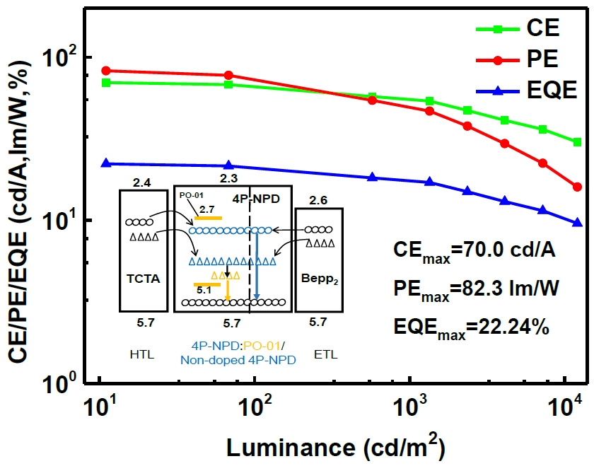
| W8 | 2.63 | 2.88 | 82.3/77.5 | 70.0/68.0 | 22.2/21.6 | 0.45, 0.45 | 3137 |
© 2019 by the authors. Licensee MDPI, Basel, Switzerland. This article is an open access article distributed under the terms and conditions of the Creative Commons Attribution (CC BY) license (http://creativecommons.org/licenses/by/4.0/).
Share and Cite
Luo, W.; Chen, X.; Sun, S.-Q.; Zhang, Y.-J.; Wang, T.-T.; Liao, L.-S.; Fung, M.-K. Management of Exciton for Highly-Efficient Hybrid White Organic Light-Emitting Diodes with a Non-Doped Blue Emissive Layer. Molecules 2019, 24, 4046. https://doi.org/10.3390/molecules24224046
Luo W, Chen X, Sun S-Q, Zhang Y-J, Wang T-T, Liao L-S, Fung M-K. Management of Exciton for Highly-Efficient Hybrid White Organic Light-Emitting Diodes with a Non-Doped Blue Emissive Layer. Molecules. 2019; 24(22):4046. https://doi.org/10.3390/molecules24224046
Chicago/Turabian StyleLuo, Wei, Xing Chen, Shuang-Qiao Sun, Yi-Jie Zhang, Tong-Tong Wang, Liang-Sheng Liao, and Man-Keung Fung. 2019. "Management of Exciton for Highly-Efficient Hybrid White Organic Light-Emitting Diodes with a Non-Doped Blue Emissive Layer" Molecules 24, no. 22: 4046. https://doi.org/10.3390/molecules24224046
APA StyleLuo, W., Chen, X., Sun, S.-Q., Zhang, Y.-J., Wang, T.-T., Liao, L.-S., & Fung, M.-K. (2019). Management of Exciton for Highly-Efficient Hybrid White Organic Light-Emitting Diodes with a Non-Doped Blue Emissive Layer. Molecules, 24(22), 4046. https://doi.org/10.3390/molecules24224046