Abstract
In this experimental research, copper to steel tubular joints were produced by electromagnetic pulse welding. In a first phase, non-supported target tubes were used in order to investigate the influence of the workpiece geometry on the weld formation and joint characteristics. For this purpose, different joint configurations were used, more specific the tube-to-rod and the tube-to-tube configurations, with target workpieces with different diameters and wall thicknesses. Also, some preliminary investigations were performed to examine a support method for the target tubes. In a second phase, suitable support systems for the target tubes were identified. The resulting welds were evaluated in terms of their leak tightness, weld length and deformation of the target tube. It can be concluded that polyurethane (PU), polymethylmethacrylaat (PMMA), polyamide (PA6.6) and steel rods can be considered as valuable internal supports leading to high-quality welds and a sufficient cross-sectional area after welding. Welds with a steel bar support exhibit the highest cross-sectional area after welding, but at the same time the obtained weld quality is lower compared to welds with a PA6.6 or PMMA support. In contrast, welds with a PA6.6 or PU support show the highest weld quality, but also have a lower cross-sectional area after welding compared to steel internal supports.
1. Introduction
Electromagnetic pulse welding is an innovative solid-state welding technology that belongs to the group of pressure welding processes; it uses electromagnetic forces for deformation and joining of materials. The process can be used to join tubular [1] and sheet metals [2], placed in the overlap configuration. If the workpieces are impacted with high velocity and under a certain angle, a jet is created along the materials’ surfaces. This jet removes surface contaminants, such as oxide films, which eliminates the need for pre-process cleaning. In general, no pre-weld cleaning is required.
A wavy or a flat bond interface is formed like in explosion welding. An intermetallic layer can be created as a result of mechanical mixing, intensive plastic deformation and local heating. The temperature increase occurs due to Joule effects and the collision itself. Since the process takes place in a very short lapse of time, heating is not sufficient to generate a temperature increase in a wide area, so there is no significant heat affected zone.
Compared to thermal welding processes, electromagnetic pulse welding offers important advantages since pressure instead of heat is employed to realize the metallic bond. Electromagnetic pulse welding is possible for similar and dissimilar material combinations, including those which are difficult or impossible to join using conventional processes [3,4,5].
Dissimilar copper (hereafter Cu) to steel (hereafter St) tubular joints are of particular interest for cooling applications in the machine and equipment construction industry. A specific example is a Cu-St tubular joint as part of a refrigeration circuit of a compressed air-dryer, which is currently produced by brazing [6].
Only very few articles discuss electromagnetic pulse welding of copper to steel [7,8,9,10]. These publications do not go into much detail however. A more comprehensive description of joining of copper to steel was provided in [11,12,13].
In Ref. [11], copper flyer tubes (Cu-DHP R290; O.D.: 25 mm) were used in combination with S235JR steel target rods, using different outer diameters to investigate the influence of the standoff distance. It was proven that high-quality welds could be created. The best results were obtained with an overlap distance of 12 mm, a low standoff distance of 1 or 1.5 mm and a high energy level. The field shaper cut resulted in a local decrease of the weld length. The interface was wavy and the wavelength and amplitude increased with increasing energy and standoff distance, as also described in literature about explosion welding.
In Ref. [12], the interface morphology of electromagnetic pulse welding between copper and carbon steel was explored. The interface morphology, diffusion of elements and the hardness distribution were investigated. Wavy and straight bonding areas were found, with weld lengths up to 5 mm. In the wavy bonding area, the wavelength and amplitude are approximately 60 and 20 μm, respectively. The width of mutual diffusion region of Cu and Fe elements was 2 µm in straight weld interfaces and increased up to 6 μm in wavy weld interfaces. The highest hardness appeared in the steel material, near the interface, while the interfacial hardness was in between the values of the 2 base materials.
In Ref. [13], joining of two tubes of pure copper and low carbon steel by electromagnetic pulse welding was described. Satisfactory welds were obtained with an optimal set of parameters. The welded interface revealed a wavy morphology with pockets of intermixed metal vortices. High resolution electron microscopy and microanalysis showed the formation of nano-grains along the interface and evidence of short distance interatomic diffusion across the weld joint respectively. The strain hardening effect due to high energy impact led to significantly higher microhardness on the steel side of the interface.
Joining of tubular parts frequently requires a support of the inner tube in order to avoid undesired deformation or fracture of the joint. Specifically, tubes with a small wall thickness need to be supported, because they can hardly resist radial forces [14]. Joining of tubular parts, for which the inner tube is not supported, has been investigated mainly for aluminum as flyer tube and steel as target (or inner) tube. Applications for aluminum to steel tubular joints are, amongst others, found in the fabrication of tubular space frame structures for automotive vehicles and pipe fittings [15].
In order to avoid deformation of the target tube, several studies have been performed regarding the critical wall thickness of the target tube and the flyer tube [14,16,17]. This critical thickness was defined as the thickness of the tube at which no plastic deformation of the target tube occurred. In addition, it was also shown that the feasibility of joining tubular products was determined by the discharge frequency [14] and the critical discharge voltage (which defines the impact velocity of the flyer tube) [15].
In this experimental research, copper to steel tubular joints were produced by electromagnetic pulse welding. In a first phase, non-supported target tubes were used, in order to investigate the influence of the workpiece geometry on the weld formation and joint characteristics. For this purpose, different joint configurations were used, more specifically the tube-to-rod and the tube-to-tube configurations, with target workpieces with different diameters and wall thicknesses. Also, some preliminary investigations were performed in order to examine a support method for the target tubes.
In a second phase, suitable support systems for the target tubes were investigated. The resulting welds were evaluated in terms of their leak tightness, weld length and deformation of the steel tube.
2. Materials and Methods
2.1. Working Principle of Electromagnetic Pulse Welding
In the electromagnetic welding process, a power supply is used to charge a capacitor bank. When the required amount of energy is stored in the capacitors, it is instantaneously released into a coil, during a very short period of time. The discharge current induces a strong transient magnetic field in the coil, which generates a magnetic pressure, that accelerates a conductive workpiece, named the flyer workpiece, up to a sufficiently high velocity. The flyer workpiece collides with a fixed workpiece (termed target workpiece) and if the conditions of the collision velocity and impact angle are favorable (collision velocity and impact angle), a weld will be created between the two parts. For a sufficiently high velocity and a non-parallel collision, jetting will occur. This phenomenon cleans the surfaces of both materials and removes oxides and other contaminants. After collision, the acting Lorentz force combined with the inertia effect press the atomically clean surfaces of the flyer and target together to form the weld. Bonding between the two materials occurs when the distance between their atoms becomes smaller than the range of their mutual attractive forces [18,19,20,21].
The charging of the capacitors typically takes around 5–20 s depending on the installation and required energy level, whereas the actual pulse discharge, acceleration and collision of the flyer only last around 10–20 µs. A schematic illustration of the electromagnetic pulse welding system is shown in Figure 1.
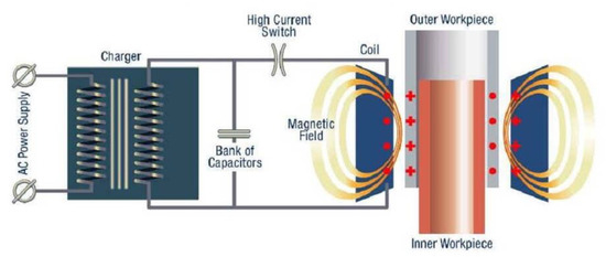
Figure 1.
Schematic illustration of the electromagnetic pulse welding process.
2.2. Set-Up of the Electromagnetic Pulse Welding System
Electromagnetic pulse welding of Cu to St tubular joints was performed using a Pulsar model 50/25 system (Bmax, Toulouse, France) with a maximum charging energy of 50 kJ (corresponding with a maximum capacitor charging voltage of 25 kV). The total capacitance of the capacitor banks equals 160 μF. The weldability of copper to steel tubes was investigated using two different coil systems, namely a single turn coil combined with a field shaper and a transformer (ratio 3:1), and a multi-turn coil with 5 turns combined with a field shaper (see Figure 2). The field shaper is a practical tool, which is mainly used for forming and joining of tubular workpieces and serves to concentrate the magnetic flux and to focus the magnetic pressure over the desired area of the workpiece. A radial cut is machined in the field shaper, to lead the induced current to the internal surface of the field shaper. At the location of the field shaper cut, a lower magnetic pressure is acting on the tube, compared to other locations.
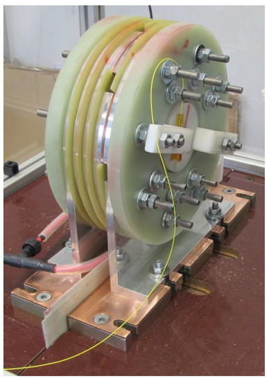
Figure 2.
Multi-turn coil used in the experiments.
2.3. Materials and Dimensions
Copper (Cu DHP R220) tubes are welded onto cold-worked carbon steel rods (11SMnPb30 + C) and tubes. The copper tubes have an outer diameter and wall thickness equal to resp. 22.22 and 0.89 mm.
The configuration of the joints is illustrated in Figure 3. The internal parts are machined as shown in this figure, using a shoulder to align the flyer and target tube. The variable welding parameters are the stand-off distance, the overlap length and the free length. The overlap length is a material-dependent parameter that influences the impact angle. The outer diameter of the steel target tube is varied to achieve stand-off distances of 1.0, 1.5 and 2.0 mm. Based on previous experimental research, the length of the tool overlap between the flyer tube and field shaper is fixed at 8 mm and the free length at 15 mm.
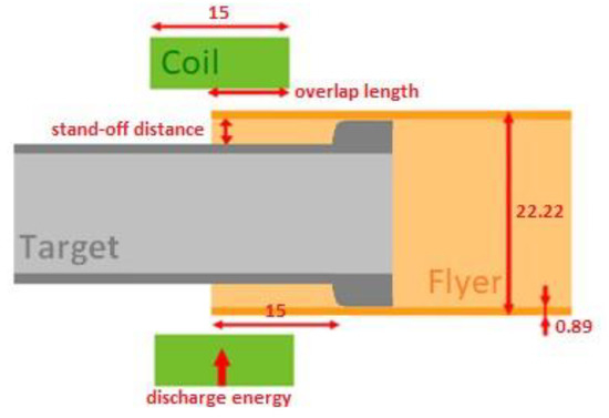
Figure 3.
Joint configuration for tube-to-tube joints.
Different joint configurations have been used in the experiments, namely tube-to-rod, tube-to-tube without internal support and tube-to-tube with internal support. An example of a tube-to-tube weld using an internal support is shown in Figure 4.
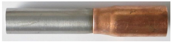
Figure 4.
Example of a tubular connection realised with electromagnetic pulse welding (copper tube outer diameter: 22.22 mm).
2.4. Weld Characterisation Methods
The weld quality was assessed based on a leak test using air and metallographic examination. In order to evaluate the effectiveness of the internal supports, the diameter of the internal part was measured prior and after the joining experiments.
No mechanical properties were measured, such as the tensile strength. It is very difficult to manufacture (standardized) tensile test specimens from the welded tubes, due to the specific shape of the welded samples, and their small size. Bend testing is also not possible, again because of the above-mentioned reasons. Moreover, for the given application, leak tightness and a defect-free weld are the most critical aspects to investigate.
2.4.1. Leak Test with Air
All welds were leak tested using air. The welded specimens were sealed at both ends, submerged into water and pressurized with an air compressor up to 9 bars. Leakage is visually detected by escaping bubbles near the weld interface, which indicate that either some severe imperfections are present, or there is no weld formation at all.
2.4.2. Metallographic Examination
Metallographic examination is performed to determine the actual cause of defective or leaking welds or to assess the quality of leak-tight welds. Hereto, the welded specimens are cross-sectioned in the longitudinal direction at the location of the field shaper cut, as the magnetic pressure is lower at this location. In this way, the weld interface at the field shaper cut as well as at 180° relative to the field shaper cut are investigated. The weld cross-sections are subjected to metallographic preparations, after which the interfacial morphology, the weld length and the reduction of the diameter of the internal part are examined and related to the welding parameters.
For welded tubular specimens, the weld length measured at the field shaper cut and 180° relative to the field shaper cut can be summarized into an arbitrarily defined parameter, called the Weld Quality Indicator (WQI). This parameter was developed by the authors and takes into account both weld lengths and the presence of a non-welded interface, observed during the metallographic examination [22]. The WQI is defined as
where:
- ●
- L1: the measured weld length near the field shaper cut,
- ●
- L2: the weld length at 180° relative to the field shaper cut,
- ●
- A: a parameter that is equal to:
- ○
- 0: if both locations contain a welded interface,
- ○
- 1: if only one location contains a welded interface (other location is for example cracked),
- ○
- 2: if at both locations no weld formation is observed.
The WQI is a measure for the weld length and the continuity of the welded interface along the circumference of the welded tubes. The color scale bar for the WQI in Figure 5 indicates a threshold value of 10, above which a weld is considered to exhibit a sufficiently high quality.
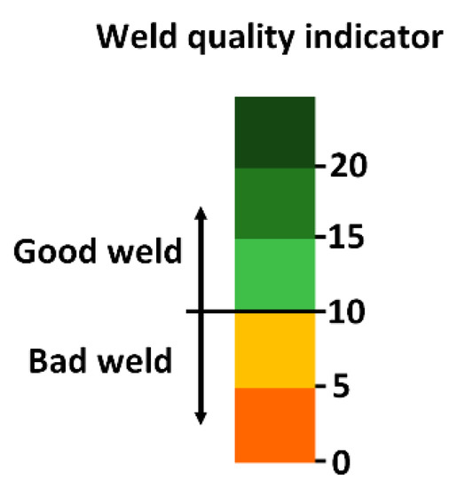
Figure 5.
WQI colour scale bar to classify the weld quality, with a threshold value of 10.
2.4.3. Reduction of the Internal Diameter of the Target Tube
Due to the impact of the flyer tube, also the internal part (the target tube) deforms. Figure 6 illustrates the reduction of the inner diameter of the target tube after welding (dafter) and the original inner diameter of the target tube (dorig). The cross-sectional area after impact is defined as: .
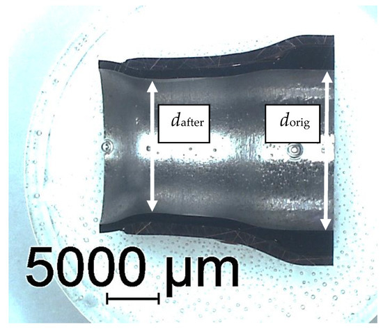
Figure 6.
Measurement of the reduction of the inner diameter (dafter) and original inner diameter (dorig) of the target tube.
2.5. Internal Supports for the Target Tubes
In order to minimize the radial deformation of the target tube during electromagnetic pulse welding, an internal support is required which is inserted into the target tube. Several types of internal supports have been documented in literature, but the majority were expensive, difficult to remove, or could not resist the severe impact energy [23,24,25,26]. If the internal support cannot be removed after the welding process, this can be considered as a process limitation when joining tubular parts for conducting liquids or gases. Therefore, in this experimental research, different other types of internal supports were explored which are preferably inexpensive, allow for easy removal and are possibly re-usable.
Two categories of internal supports have been considered. The first category concerns re-usable internal supports that are able to withstand the impact several times without failure. These internal supports should be extracted after welding by a manual or mechanical operation (e.g., a hydraulic or pneumatic press). The second category are internal supports that are not re-usable, but can be removed without direct access to the support. In this way, the support can also be used for long bended tubular connections within for example a refrigeration circuit.
Possible materials were selected and compared, based on the relevant requirements of the internal support. For the first category, i.e. the re-usable internal supports, a material that has a high fracture toughness and that does not break in a brittle manner is envisioned. Hence, polyurethane (PU) and polyamide (PA6.6) is considered, since both exhibit a high fracture toughness. A steel bar was considered as well.
For the second category, i.e., the non-re-usable internal supports, a first option is that the material can be melted or dissolved in a fluid and hence a low melting point and a high solubility are important. This leads to the selection of ice, which can be melted after welding, and plaster, which could offer the possibility to dissolve into a fluid. The ice was made using normal water. The ice was kept at a temperature of −18 °C prior to the welding experiment and used immediately in order to prevent melting. The plaster had a hardness of 46 N/mm, a porosity level of 46% and a plaster/water mixing ratio of 1.61 kg per liter of water.
Another property relevant for the non-reusable support is the brittleness, so that the material can withstand the first moment of impact, but easily fractures afterwards. In this way, the remains of the material can be removed by pressurized air. Hence, a material with a low fracture toughness is preferred, which leads to the selection of polymethylmethacrylate (PMMA), which is a very brittle composite. For this material, different configurations (rods, series of disks, and tube) were examined. The selected materials for the internal support are summarized in Table 1 and the corresponding configurations are illustrated in Figure 7, Figure 8, Figure 9 and Figure 10.

Table 1.
Materials and dimensions of the internal supports.
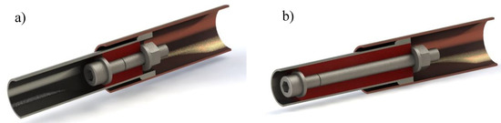
Figure 7.
Joint configuration with an internal support of PU and M8 bolts (a) length of 30 mm; (b) length of 50 mm.
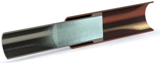
Figure 8.
Joint configurations with an internal support of ice.
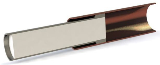
Figure 9.
Joint configurations with an internal support of plaster.
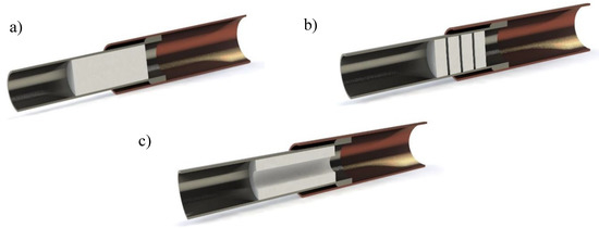
Figure 10.
Joint configurations with an internal support of PMMA: (a) Rod; (b) 4 disks with a length of 5 mm each (gaps between the disks are exaggerated for illustrative purposes); (c) tube.
3. Results
3.1. Overview of Experimental Work
During the experimental investigations, different aspects have been examined for manufacturing of tubular Cu-St joints, which were conducted into 2 phases:
- First phase: Influence of the process parameters and the workpiece geometry on the weld formation and joint characteristics. For this purpose, experiments were performed using target rods as a reference and target tubes with wall thicknesses of 1, 2 and 3 mm, without internal support. The purpose was to investigate the effect of the target tube wall thickness on the joint characteristics and the deformation of the target tube during welding. Also, tube-to-tube joints with a target tube with a wall thickness of 1 mm were manufactured using an internal PU-support for comparison.
- Second phase: Investigation of suitable support systems for the target tube with a wall thickness of 1 mm
3.2. Influence of the Process Parameters and the Workpiece Geometry on the Joint Characteristics
For all joint configurations, the internal workpieces were machined in the welding zone to a specific diameter, in order to obtain the desired value for the stand-off distance between the flyer tube and the target workpiece (1.0–1.5 & 2.0 mm). Besides this parameter, also the discharge energy was varied between 18 and 22 kJ. The free length, defined as the overlap distance of the flyer tube and the internal workpiece, was fixed at 15 mm. These parameter values are based on previous experimental work in the frame of the Join’EM project [27]. Also, the overlap between the flyer tube and the field shaper was fixed at 8 mm. The experiments were performed with the single turn coil with field shaper.
The WQI and the reduction of the internal diameter of the target tube were compared for the tube-to-rod configuration and the tube-to-tube configurations with the 3 different wall thicknesses of 1, 2 and 3 mm. In this way, the effect of the wall thickness of the target tube on the WQI and the reduction of the inner diameter of the target tube could be identified.
All of the optimized and semi-optimized welds were leak tight using the air leak test described in Section 2.4.1. Only the welds showing an excessive deformation of the internal part showed small leaks. The investigation described in Section 3.3 was performed using leak-tight welds.
3.2.1. Range of Weld Lengths and Reduction of the Inner Diameter of Leak Tight Welds
Table 2 summarizes the range of the measured weld lengths and the reduction of the internal diameter of the target tube of all leak tight welds created during the experimental investigation. Figure 11 shows a comparison of the metallographic specimens of the different configurations investigated.
Table 2.
Range of measured weld lengths and reduction of the internal diameter of the target tube of leak tight welds.
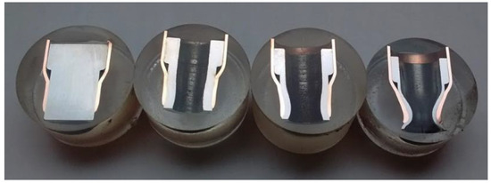
Figure 11.
Metallographic specimens of typical welds: (left to right) Tube-to-rod, tube-to-tube with a target tube with a wall thickness of 3, 2 and 1 mm.
3.2.2. Influence of the Welding Parameters and the Wall Thickness of the Target Tube on the WQI
The effect of the stand-off distance on the weld quality represented by the value of the WQI of the tube-to-rod specimens and the tube-to-tube specimens with the 3 different wall thicknesses of the steel target tube is illustrated in Figure 12, whereas the effect of the discharge energy for a fixed stand-off distance of 2 mm is shown in Figure 13. Similar graphs have been composed for other values of the discharge energy or the stand-off distance.
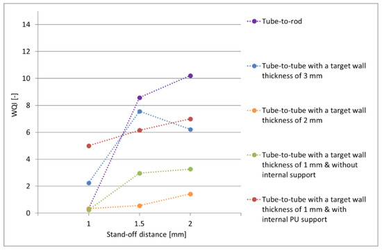
Figure 12.
WQI as a function of the stand-off distance. Fixed discharge energy = 20 kJ.
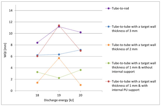
Figure 13.
WQI as a function of the discharge energy. Fixed stand-off distance = 2 mm.
In particular, the stand-off distance significantly affects the WQI: a stand-off distance of 2 mm usually results in the largest WQI, as observed in the metallographic examinations. This indicates that 2 mm is a sufficient distance over which the flyer tube can accelerate and reach the required impact velocity for weld formation. In contrast, the shorter weld lengths measured for welds produced with a stand-off distance of 1 and 1.5 mm might indicate that these distances are too small for the flyer tube to reach a sufficient velocity. A stand-off distance of 1 mm usually resulted in a discontinuous weld interface.
In general, no clear correlation between the WQI and the discharge energy is identified (see Figure 13). At a medium discharge energy of 19 kJ, the WQI either reaches a minimum or maximum for the different stand-off distances.
The highest WQI values are obtained for tube-to-rod specimens, for tube-to-tube specimens with a large wall thickness of the target tube or for tube-to-tube specimens with supported target tubes, as observed in the metallographic examination of the weld interface. The use of an internal support also results in an increase of the WQI with a factor up to 4, compared to unsupported tube-to-tube specimens (compare the red and the green curve in Figure 12).
A smaller wall thickness of the target tube leads to a deterioration of the leak tightness of the welds. Moreover, a shift from a continuous to a discontinuous weld interface with a smaller weld length was observed. The center of the welded region appeared to be the weakest part of the weld and when failure occurred, it usually initiated from this location.
Based on these results, it is concluded that a stand-off distance between 1.5 and 2 mm combined with a discharge energy between 18 and 20 kJ leads to high-quality welds. The optimum overlap length equals 8 mm and the free length equals 15 mm.
A general overview of an optimized weld for the tube-to-rod configuration weld is shown in Figure 14. At the weld start (left in Figure 14), an unwelded zone is observed, because at this location, the welding parameters likely are outside of the window of suitable process parameters to obtain a metallic bond. Further to the right, the weld interface is flat or slightly wavy, without any visible intermetallic layers (see Figure 15). Towards the middle region of the welded interface, the waviness and the amount and thickness of intermetallic phases increase (see Figure 16 and Figure 17). Towards the weld end, again an unwelded interface is observed, because of the same reasons at the weld start.
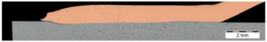
Figure 14.
Cross section of an optimised tube-to-rod weld.
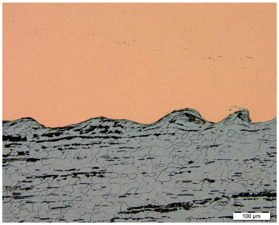
Figure 15.
Weld interface at the weld start.
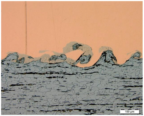
Figure 16.
Weld interface at the middle of the weld.

Figure 17.
Detail of Figure 16.
A small area in the middle of the weld interface (Figure 18) was selected for elemental mapping, line scanning and semi-quantitative chemical composition determination using Scanning Electron Microscopy (SEM; JEOL JSM-7600F Analytical Ultrahigh Resolution TFEG-SEM scanning electron microscope, Tokyo, Japan) coupled with Energy Dispersive X-Ray Spectroscopy (EDX).
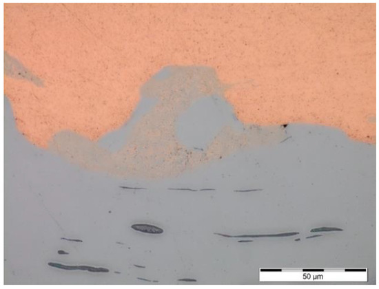
Figure 18.
Optical micrograph of the middle of the weld interface.
As illustrated in Figure 18 and Figure 19, an interfacial layer is present in the middle of the weld interface. Elemental mapping of this particular zone illustrates that the intermixed region is randomly dispersed within the steel material and is mainly composed of Cu (see Figure 20 and Figure 21). Moreover, the alloying elements Mn and S are clearly detected in the steel material (see Figure 22 and Figure 23). A line scan of the area shown in Figure 18 confirms that vigorous intermixing has taken place at the weld interface (see Figure 24). The semi-quantitative chemical composition detected by EDX shows that Cu is the dominant element in the interfacial layer (59.7 wt%), compared to Fe (39.8 wt%), as illustrated in the EDX spectrum in Figure 25 and Table 3. In the proximity of the weld interface, Cu (99.1 wt%) and Fe (98.4 wt%) are the main elements at either side of the interface.
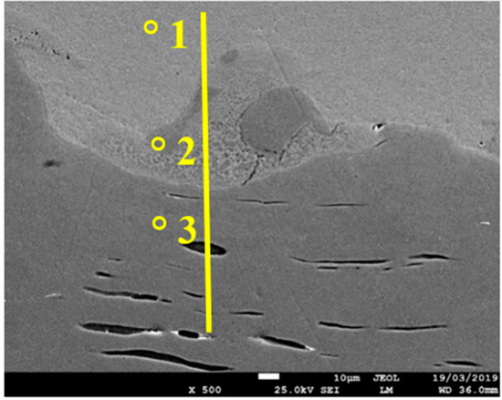
Figure 19.
SEM micrograph of the zone shown in Figure 18, micrograph with indication of the line scan and points for semi-quantitative chemical composition.
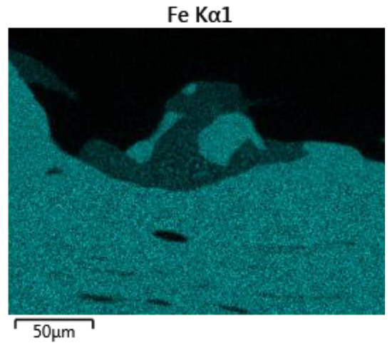
Figure 20.
Element mapping of Fe in the zone shown in Figure 18.
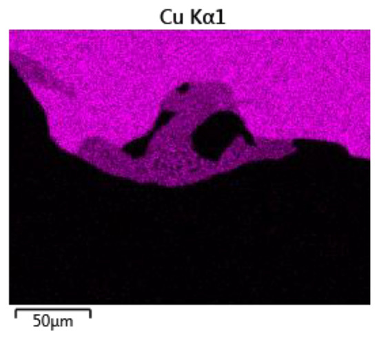
Figure 21.
Element mapping of Cu in the zone shown in Figure 18.
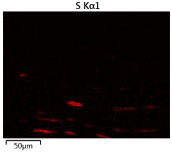
Figure 22.
Element mapping of S in the zone shown in Figure 18.
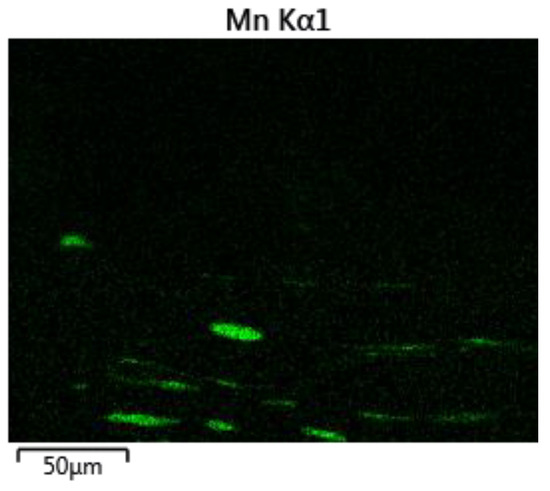
Figure 23.
Element mapping of Mn in the zone shown in Figure 18.
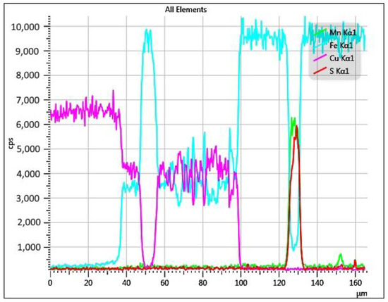
Figure 24.
Line scan performed at the middle of the weld interface in Figure 18.
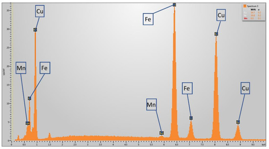
Figure 25.
EDX spectrum of the interfacial layer in Figure 18 (point number 2).
Table 3.
Semi-quantitative chemical composition by SEM-EDX, performed in the middle of the weld interface in Figure 18.
The tube-to-tube joints exhibit a large radial deformation, especially when the target tube has a small wall thickness. Due to this, they are more sensitive for failure of the weld. The defective welds resemble as if they fracture after weld formation. Severe shearing of grains, waviness and some intermetallic phases are present at the broken weld interface, similar to successful welds, indicating sufficient energy is present to create a good weld. However, fracture of the weld interface is not caused by intermetallic layers, as they are not present in the majority of the fractured weld interface. The welding speed, also known as the collision point velocity, is much higher than the deformation rate of the target tube in the radial direction. Therefore, it is possible that the weld is created prior to the initiation of the deformation of the target tube in the radial direction [28]. In other words, the target tube only starts to decrease in diameter after the weld has been formed. Based on this, a possible hypothesis is that the weld was not sufficiently strong to withstand the forces caused by the radial inward deformation of the target tube and thus failure at the weld interface occurs. An example of such a failure is shown in Figure 26, compared to a sound weld interface observed in a tube-to-rod specimen, which does not exhibit any radial deformation. In Figure 26a, some porosities might be present, as a consequence of local melting and rapid solidification. Further investigation is however required to identify the cause of these porosities.
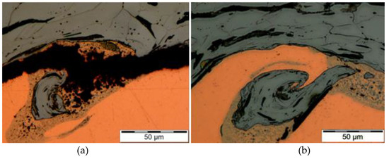
Figure 26.
Weld produced with a stand-off distance of 2 mm. (a) Detail of the weld interface of a fractured tube-to-tube specimen with a target tube with a wall thickness of 2 mm. (b) Sound tube-to-rod specimen.
3.2.3. Influence of the Welding Parameters and the Wall Thickness of the Target Tube on the Deformation of the Target Tube
The effect of the stand-off distance on the reduction of the internal diameter of the steel target tubes for the 3 different wall thicknesses is illustrated in Figure 27, whereas the effect of the discharge energy is shown in Figure 28.
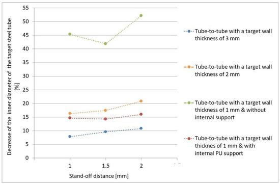
Figure 27.
Decrease of the inner diameter of the steel target tube as a function of the stand-off distance. Fixed discharge energy = 20 kJ.
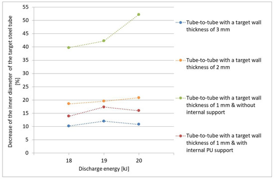
Figure 28.
Decrease of the inner diameter of the steel target tube as a function of the discharge energy. Fixed stand-off distance = 2 mm.
A larger stand-off distance results in a larger decrease of the inner diameter, as the flyer can accelerate over a longer distance. This assumes that the flyer has not reached its deceleration point yet over a distance of 2 mm. Also, a higher discharge energy contributes to a larger reduction of the inner diameter, due to more energy being available for deformation.
In general, the inner diameter of the steel target tube after welding decreases for a smaller wall thickness of the target tube, due to the smaller resistance against deformation. For the smallest wall thickness of 1 mm of the target tube, the radial deformation of the target tube becomes irregular for some parameter combinations irregular and the occurrence of buckling is observed.
Moreover, the reduction of the inner diameter of tube-to-tube specimens with a wall thickness of 1 mm is more than twice the amount measured at the target tubes with a wall thickness of 2 and 3 mm. This amount of deformation is most likely unacceptable, as it causes a decrease of the inner diameter of up to 52%. This is equal to a loss of 75% of the inner tube area, which is very critical in for example fluid applications.
Some preliminary experiments were performed with an internal PU-support. This leads to a smaller reduction of the inner diameter of the target tubes with a factor up to 3.4, and an increase of the weld length by a factor up to 4, compared to unsupported tubes. The reduction of the inner diameter for supported tube-to-tube specimens is less dependent on the variation of the stand-off distance and discharge energy.
3.3. Investigation of Suitable Support Systems for the Target Tubes
In the experiments described in the previous section, a single-turn coil combined with a field shaper and a transformer was used. However, most of the welds had a WQI value below the threshold value of 10. Hence, the use of a multi-turn coil was considered, which leads to a higher frequency and hence a lower skin depth, resulting in an improvement of the process efficiency. The use of the multi-turn coil leads to a better weld quality and an improvement of the joint properties, compared to the use of a single turn coil. These investigations fall outside of the scope of this publication.
A high-quality weld produced by electromagnetic pulse welding should meet the following requirements:
- Leak tight
- Interfacial morphology with no or limited porosities and cracks and a sufficiently long welded interface at either side of the specimen. This corresponds with a WQI value of at least 10.
- Smallest possible reduction of the internal diameter of the target tube, such that a large cross-sectional area is maintained after welding. A qualitative support gives rise to a cross-sectional area after impact of at least 100 mm². This value was defined based on the application.
For this purpose, different internal supports were investigated, as detailed in Section 2.5. Similar as in the previous test series, for all joint configurations, the stand-off distance between the flyer tube and the target workpiece was varied at 1.0, 1.5 and 2.0 mm. Also, the discharge energy was varied between 18 and 22 kJ. The free length and the overlap between the flyer tube and the field shaper was again fixed at 15 and 8 mm, respectively.
In order to evaluate the quality of the different internal supports, the cross-sectional area after welding is visualized in Figure 29 as a function of the WQI for the different joint configurations that produced leak tight joints. Leaking joints were thus excluded from this graph. The tube-to-tube joint configurations without an internal support are included as a reference. The green area contains leak tight welds that fulfil all the requirements listed above for being classified as a high-quality weld (i.e., WQI > 10 and internal cross section > 100 mm2). The yellow area contains welds that are leak tight, but only meet the requirement for either the WQI or the cross-sectional area. The red area contains leak tight welds that have a WQI and cross-sectional area below the minimum required values. All results of the different support methods are summarized in Table 4.
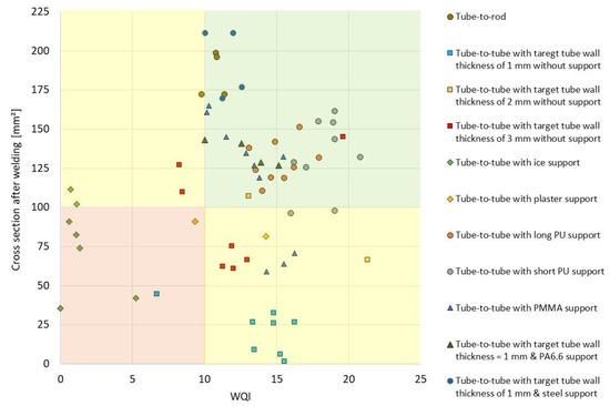
Figure 29.
Cross-sectional area after welding as a function of the WQI for the different joint configurations.
Table 4.
Evaluation of the different types of internal support.
In general, a trade-off exists between the cross-sectional area after welding and the WQI: Welds with a larger remaining internal section after welding exhibit a lower WQI and vice versa. When using a higher discharge energy, a longer weld length is obtained, but also more deformation is observed of the target tube.
For the tube-to-tube joint configuration without internal support (blue, yellow and red square markers in Figure 29), the wall thickness of the target tube has a significant effect on the cross-sectional area after welding. When the target tube has a larger wall thickness, the cross-sectional area prior to impact is smaller, compared to a target tube with a smaller wall thickness. However, at the same time, the reduction of the cross-sectional area is significantly less and hence the cross-sectional area remaining after impact is larger for a target tube with a larger wall thickness. None of the joints performed without internal support fulfil the requirements listed above.
Ice and plaster are excluded as valuable support methods support (green and yellow rhombus markers in Figure 29) because of the low obtained joint quality in the case of ice, or because of the small remaining cross-sectional area after welding in the case of plaster. Other disadvantages of these support methods are mentioned in Table 4.
Tube-to-rod welds (green circle markers in Figure 29) exhibit a continuous weld interface with the highest cross-sectional area after welding (in the assumption that the solid target workpieces are machined to tubular workpieces with a wall thickness of 1 mm) and hence the lowest reduction of the inner diameter. However, the WQI is smaller compared to tube-to-tube configurations with a target tube with an internal support.
It can be concluded that PU, PMMA, PA6.6 and steel rods can be considered as valuable internal supports leading to high-quality welds and a sufficient cross-sectional area after welding. Welds with a steel bar support (blue circle markers in Figure 29) exhibit the highest cross-sectional area after welding, but at the same time their WQI is lower compared to welds with a PA6.6 or PMMA supports (blue and green triangle markers in Figure 29). In contrast, welds with a PA6.6 or PU support show the highest WQI, but also have a lower cross-sectional area after welding compared to steel internal supports.
Furthermore, welds which are situated at the threshold value of the WQI usually contain a discontinuous weld interface. In contrast, no correlation between the cross-sectional area after welding and the quality of the weld interface is identified. A discontinuous weld interface can thus occur for all values of the cross-sectional area after welding ranging from 100 mm² up to the maximum measured. In other words, a large reduction of the inner diameter of the target tube does not necessarily have a negative impact on the quality of the weld interface.
Table 4 summarizes the experimental results of the different internal supports, together with their practical advantages and disadvantages. The values for the WQI and the remaining internal cross-section after welding are the highest values achieved for each internal support.
4. Conclusions
The weldability of copper tubes onto steel rods and tubes was investigated. The steel target tubes had different wall thicknesses and the use of different internal supports was examined. The welding process was performed with a single-turn coil with a field shaper and transformer and in a next stage with a multi-turn coil with a field shaper. The welding parameters that were varied were the stand-off distance and discharge energy.
In a first phase, the influence of the workpiece geometry on the weld formation and joint characteristics was investigated. Different joint configurations were used, more specific the tube-to-rod and the tube-to-tube configurations, with target workpieces with different diameters and wall thicknesses. On the one hand, a larger stand-off distance or a higher discharge energy resulted in a larger reduction of the inner diameter of the target tube. On the other hand, a stand-off distance of 1.5 and 2 mm usually lead to a higher weld quality, compared to a stand-off distance of 1 mm. However, the latter usually resulted in a discontinuous weld interface. No clear correlation between the discharge energy and the weld quality (expressed by the WQI) was identified. A smaller wall thickness of the target tube leads to a deterioration of the leak tightness of the weld. The tube-to-rod specimens exhibited the highest WQI values, compared to the tube-to-tube specimens with target tubes with different wall thicknesses.
In a second phase, suitable internal supports for target tubes with a wall thickness of 1 mm were identified. As a comparison, also experiments with a steel rod as target workpiece were conducted, which were machined afterwards to a steel tube with a wall thickness of 1 mm.
In order to evaluate the usefulness of the different internal supports, the remaining internal cross-section as a function of the WQI for the different joint configurations that produce leak tight joints was plotted. It can be concluded that PU, PMMA, PA6.6 or steel rods can be considered as valuable internal supports leading to high-quality welds with a sufficiently large internal cross- section after welding. In contrast, ice or plaster did not fulfil the requirements because of an inferior weld quality, or because of an excessive deformation of the target workpiece.
Author Contributions
Conceptualization, K.F.; methodology, K.F. and W.D.W.; validation, K.F. and W.D.W.; investigation, K.F. and I.K.; writing—original draft preparation, K.F.; writing—review and editing, W.D.W.; project administration, K.F.; funding acquisition, K.F.
Funding
The results presented in this experimental research were achieved within the project JOINing of copper to steel by ElectroMagnetic fields—“JOIN’EM”. This project was funded by the European Union within the framework of the Horizon 2020 research and innovation program under Grant Agreement No. 677660.
Conflicts of Interest
The authors declare no conflict of interest.
References
- Faes, K.; Zaitov, O.; De Waele, W. Joining of Dissimilar Materials using the Electromagnetic Pulse Technology. In Proceedings of the ASM conference Trends in Welding Research, Chicago, IL, USA, 4–8 June 2012. [Google Scholar]
- Kwee, I.; Psyk, V.; Faes, K. Effect of the Welding Parameters on the Structural and Mechanical Properties of Aluminium and Copper Sheet Joints by Electromagnetic Pulse Welding. World J. Eng. Technol. 2016, 4, 538–561. [Google Scholar] [CrossRef]
- Sapanathan, T.; Raoelison, R.N.; Buiron, N.; Rachik, M. Magnetic Pulse Welding: An Innovative Joining Technology for Similar and Dissimilar Metal Pairs. In Joining Technologies; Ishak, M., Ed.; IntechOpen: London, UK, 2016. [Google Scholar]
- Faes, K.; Kwee, I. Morphological and mechanical characteristics of aluminium-copper sheet joints by electromagnetic pulse welding. In Proceedings of the International Conference of High Speed Forming (ICHSF), Dortmund, Germany, 27–28 April 2016; pp. 299–308. [Google Scholar]
- Verstraete, J.; De Waele, W.; Faes, K. Magnetic pulse welding: lessons to be learned from explosive welding. In Proceedings of the conference Sustainable Construction and Design 2011, Department of Mechanical Construction and Production, Ghent University, Ghent, Belgium, 16–17 February 2011. [Google Scholar]
- Join’EM project objectives. Available online: http://www.join-em.eu/objectives.html (accessed on 2 April 2019).
- Kallee, S.; Schäfer, R.; Pasquale, P. Automotive Applications of Electromagnetic Pulse Technology (EMPT). Available online: http://www.english.pstproducts.com/Automotive%20Applications%20of%20EMPT.pdf (accessed on 2 April 2019).
- Vinitha, G.; Gupta, P.; Kulkarni, M.R.; Saroj, P.C.; Mittal, R.K. Estimation of charging voltage for electromagnetic welding. In Proceedings of the Annual International Conference on Emerging Research Areas: Magnetics, Machines and Drives (AICERA/iCMMD), Kottayam, India, 24–26 July 2014; pp. 1–4. [Google Scholar] [CrossRef]
- Kudiyarasan, S.; Vendan, S.A. Magnetic Pulse Welding of Two Dissimilar Materials with Various Combinations Adopted in Nuclear Applications. Indian J. Sci. Technol. 2015, 8. [Google Scholar] [CrossRef]
- Kudiyarasan, S.; Arungalai Vendan, S. Joining of Two Dissimilar Materials in Various Combinations by Using Magnetic Pulse Welding. Int. J. Interdisciplin. Res. Innovations 2016, 4, 89–100. [Google Scholar]
- Verstraete, J. Magnetic pulse welding. Master’s Thesis, Department of Mechanical Construction and Production, Faculty of Engineering, Ghent University, Ghent, Belgium, 1 June 2011. [Google Scholar]
- Yu, H.; Fan, Z.; Zhao, Y.; Li, C. Research on magnetic pulse welding interface of copper-carbon steel. Mater. Sci. Technol. 2015, 23, 1–6. [Google Scholar]
- Patra, S.; Singh Aroraa, K.; Shome, M.; Bysakh, S. Interface Characteristics and Performance of Magnetic Pulse Welded Copper-Steel Tubes. J. Mater. Process. Technol. 2017, 245, 278–286. [Google Scholar] [CrossRef]
- Lueg-Althoff, J.; Gies, S.; Tekkaya, A.E.; Bellmann, J.; Beyer, E.; Schulze, S. Magnetic pulse welding of dissimilar metals in tube-to-tube configuration. In Proceedings of the 9th International Welding Symposium of Japan Welding Society, Tokyo, Japan, 11–14 October 2016; pp. 87–90. [Google Scholar]
- Xu, Z.; Cui, J.; Yu, H.; Li, C. Research on the impact velocity of magnetic impulse welding of pipe fitting. Mater. Des. 2013, 49, 736–745. [Google Scholar] [CrossRef]
- Cui, J.; Sun, G.; Xu, J.; Xu, Z.; Huang, X.; Li, G. A study on the critical wall thickness of the inner tube for magnetic pulse welding of tubular Al-Fe parts. J. Mater. Process. Technol. 2016, 227, 138–146. [Google Scholar] [CrossRef]
- Lueg-Althoff, J.; Schilling, B.; Bellmann, J.; Gies, S.; Schulze, S.; Tekkaya, A.E.; Beyer, E. Influence of the wall thicknesses on the joint quality during magnetic pulse welding in tube-to-tube configuration. In Proceedings of the 7th International Conference on High Speed Forming, Dortmund, Germany, 27–28 April 2016; pp. 259–268. [Google Scholar]
- Kwee, I.; Faes, K. Interfacial Morphology and Mechanical Properties of Aluminium to Copper Sheet Joints by Electromagnetic Pulse Welding. Key Eng. Mater. 2016, 710, 109–114. [Google Scholar] [CrossRef]
- Stern, A.; Shribman, V.; Ben-Artzy, A.; Aizenshtein, M. Interface phenomena and bonding mechanism in magnetic pulse welding. J. Mater. Eng. Perform. 2014, 23, 3449–3458. [Google Scholar] [CrossRef]
- Kore, S.D.; Date, P.P.; Kulkarni, S.V. Effect of process parameters on electromagnetic impact welding of aluminum sheets. Int. J. Impact Eng. 2007, 34, 1327–1341. [Google Scholar] [CrossRef]
- Cui, J.; Sun, G.; Li, G.; Xu, Z.; Chu, P.K. Specific wave interface and its formation during magnetic pulse welding. Appl. Phys. Lett. 2014, 105, 221901. [Google Scholar] [CrossRef]
- Simoen, S. Investigation of the weldability of dissimilar metals using the electromagnetic welding process. Master’s Thesis, Department of Electrical Energy, Metals, Mechanical Constructions & Systems, Ghent University, Ghent, Belgium, 1 June 2017. [Google Scholar]
- Roeygens, L.; De Waele, W. Faes, Experimental investigation of the weldability of tubular dissimilar materials using the electromagnetic welding process. In Proceedings of the conference Sustainable Construction and Design, Department of Mechanical Construction and Production, Ghent University, Ghent, Belgium, 1 June 2017. [Google Scholar]
- Lueg-Althoff, J.; Bellmann, J.; Gies, S.; Schulze, S.; Tekkaya, A.E.; Beyer, E. Magnetic Pulse Welding of Tubes: Ensuring the Stability of the Inner Diameter. In Proceedings of the 6th Euro-Asian Pulsed Power Conference, EAPPC 2016: Held with the 21st International Conference on High-Power Particle Beams (BEAMS 2016) and the 15th International Conference on Megagauss Magnetic Field Generation (MG-XV); Estoril, Portugal, 18–22 September 2016; pp. 504–507, ISBN 978-1-5108-4607-4. [Google Scholar]
- Lueg-Althoff, J.; Bellmann, J.; Gies, S.; Schulze, S.; Tekkaya, A.E.; Beyer, E. Magnetic Pulse Welding of Dissimilar Metals in Tube-to-Tube Configuration. In Proceedings of the 10th International Conference on Trends in Welding Research and 9th International Welding Symposium of Japan Welding Society, Tokyo, Japan, 11–14 October 2016; Volume 1, pp. 87–90, ISBN 978-1-5108-4403-2. [Google Scholar]
- Bertelsbeck, S.; Geyer, M.; Böhm, S. Magnetic impulse welding of flexible tubes. IIW document SC-Auto-56-12. Available online: www.iiwelding.org (accessed on 30 April 2019).
- JOINing of copper to aluminium by ElectroMagnetic fields (Join’EM). Project with funding from the European Union’s Horizon 2020 research and innovation programme under grant agreement No. H2020-FoF-2014-677660 - JOIN-EM. Available online: http://www.join-em.eu/ (accessed on 2 April 2019).
- Ben-Artzy, A.; Stern, A.; Frage, N.; Shribman, V.; Sadot, O. Wave formation mechanism in magnetic pulse welding. Int. J. Impact Eng. 2010, 37, 397–404. [Google Scholar] [CrossRef]
© 2019 by the authors. Licensee MDPI, Basel, Switzerland. This article is an open access article distributed under the terms and conditions of the Creative Commons Attribution (CC BY) license (http://creativecommons.org/licenses/by/4.0/).