Resistance Spot Welding of Aluminum Alloy and Carbon Steel with Spooling Process Tapes


Abstract
:1. Introduction
2. Experimental Procedure
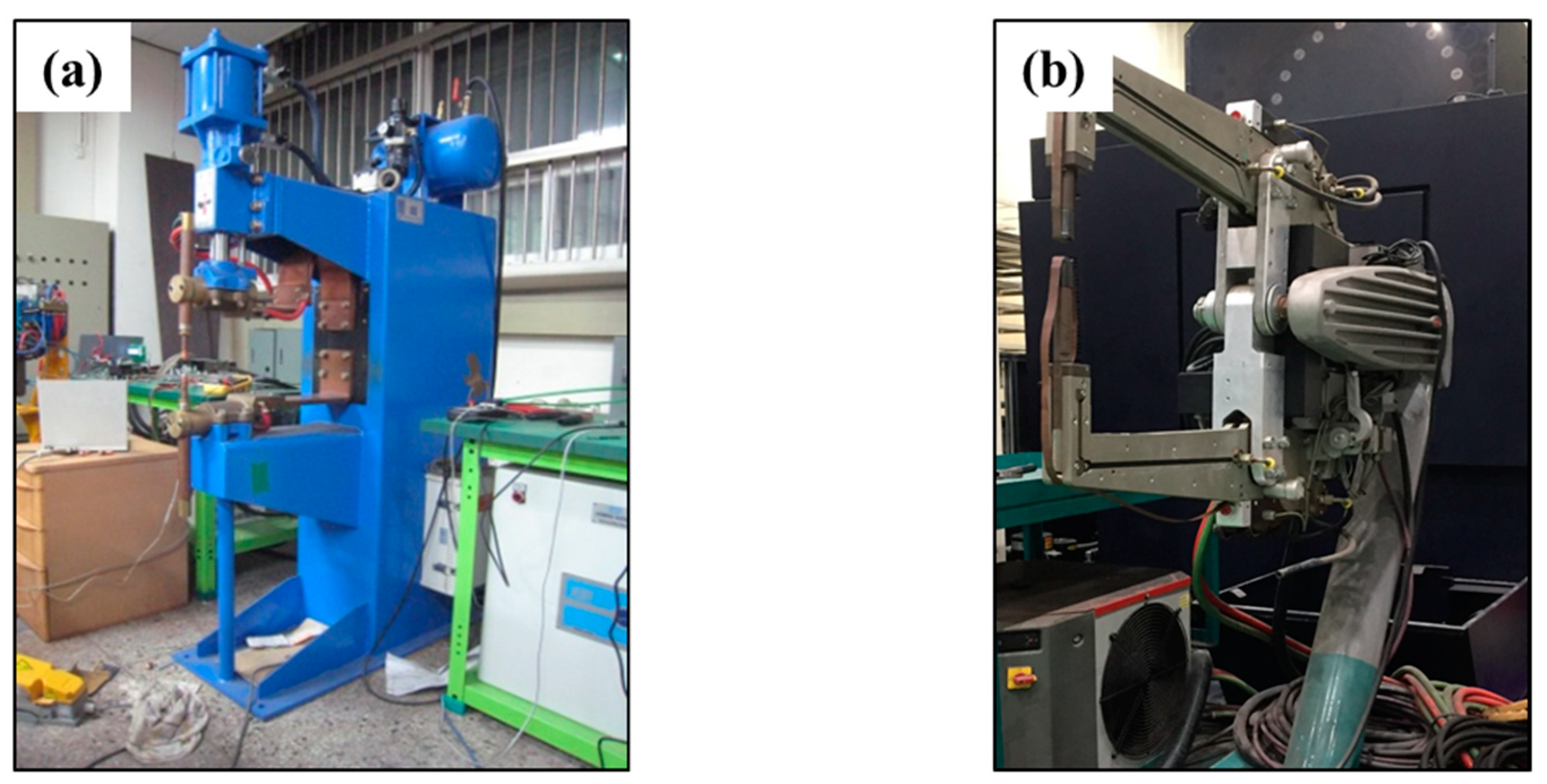
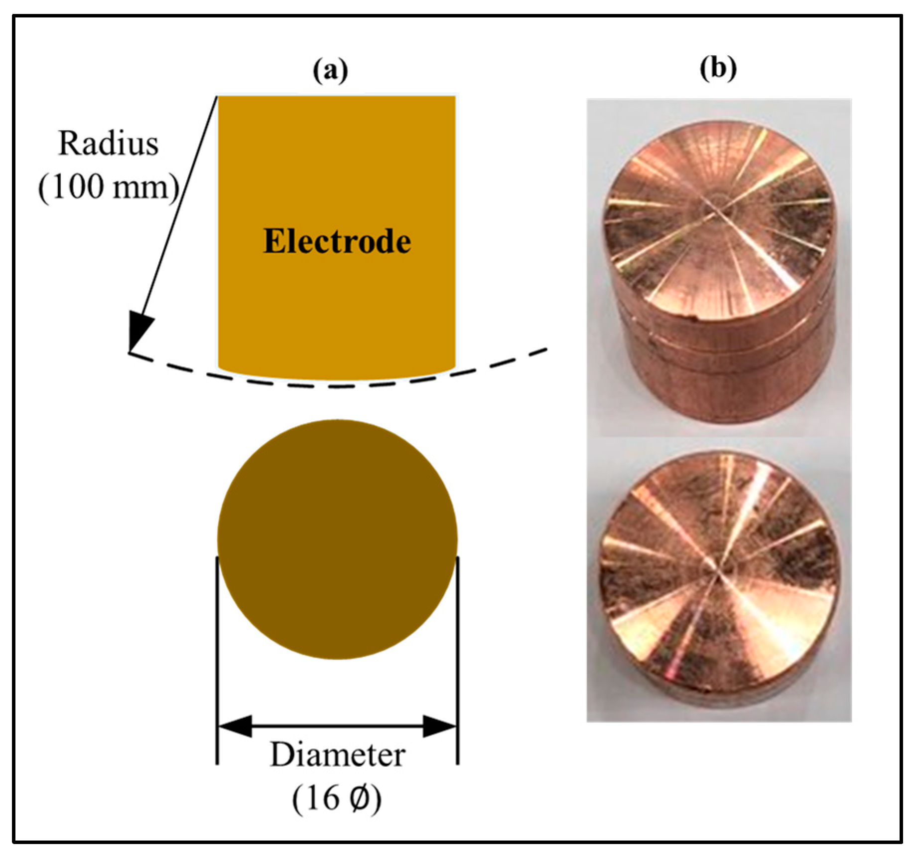
2.1. Equipment
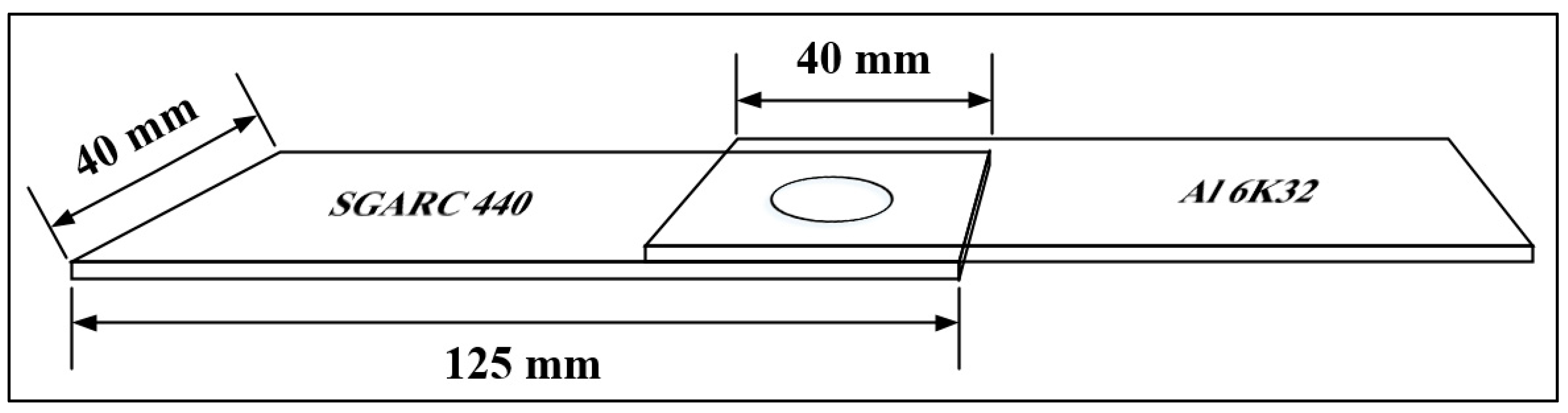
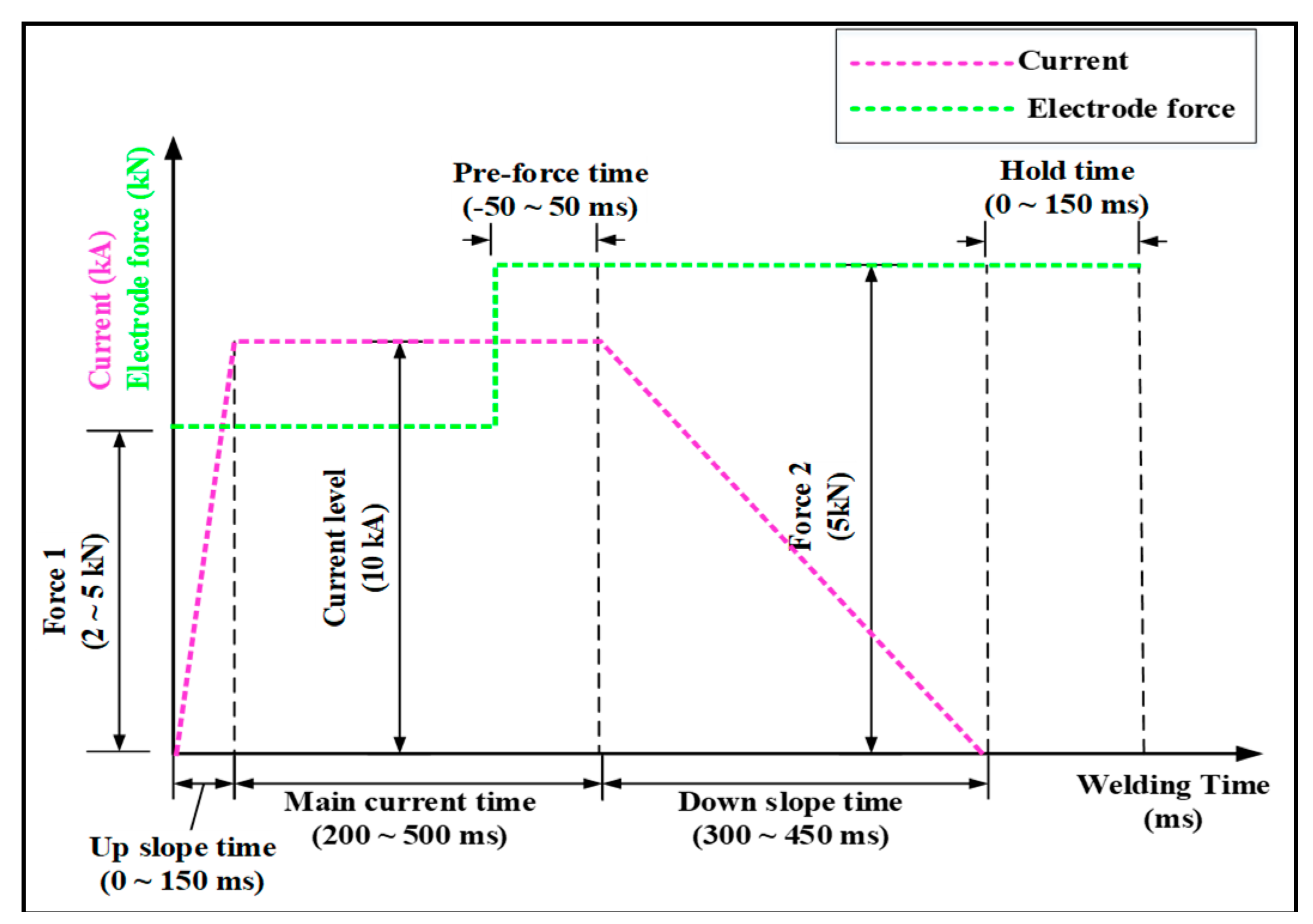
2.2. Materials and Experimental Method
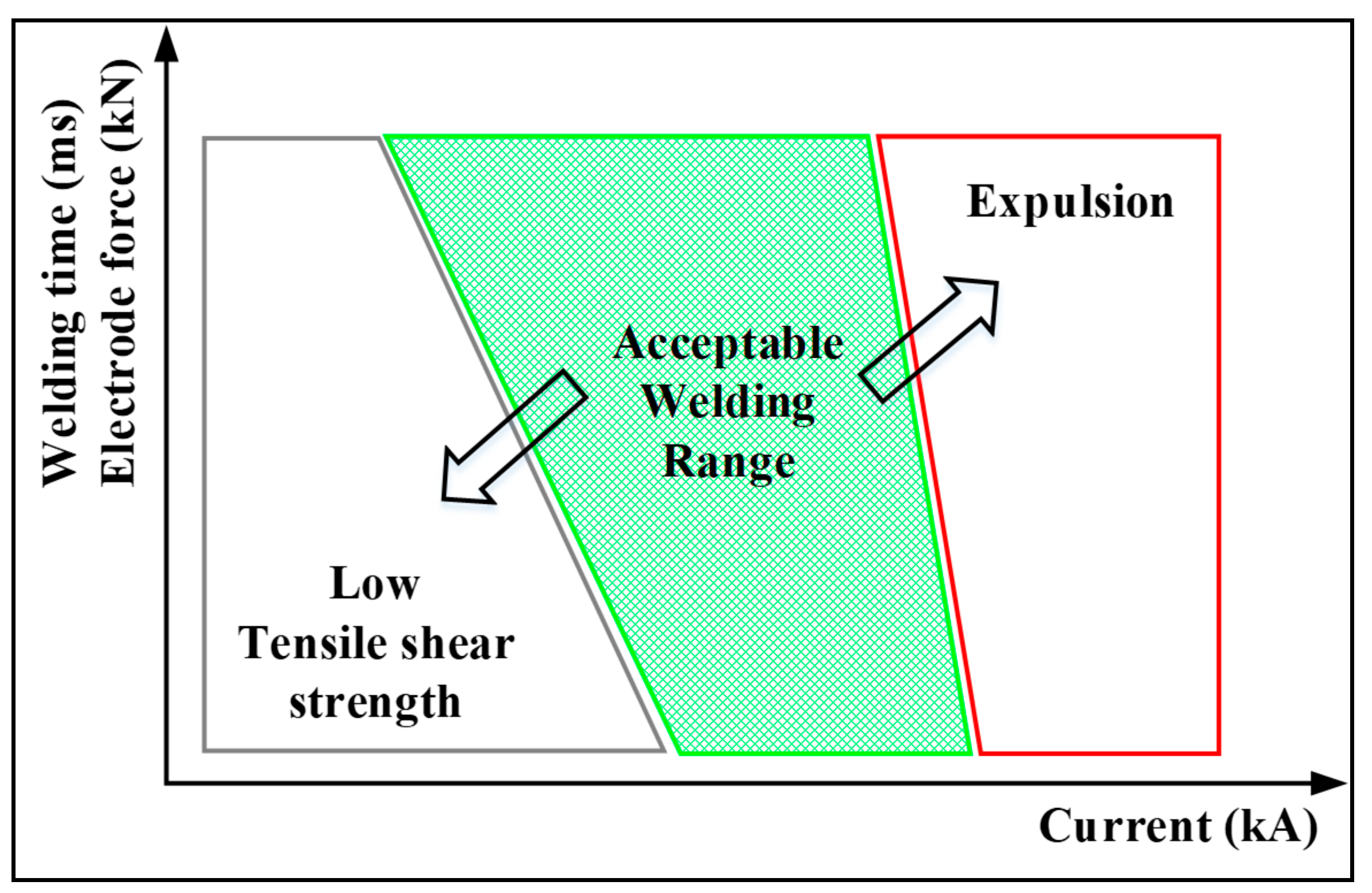
2.3. Weldability Evaluation Method
3. Results and Discussion
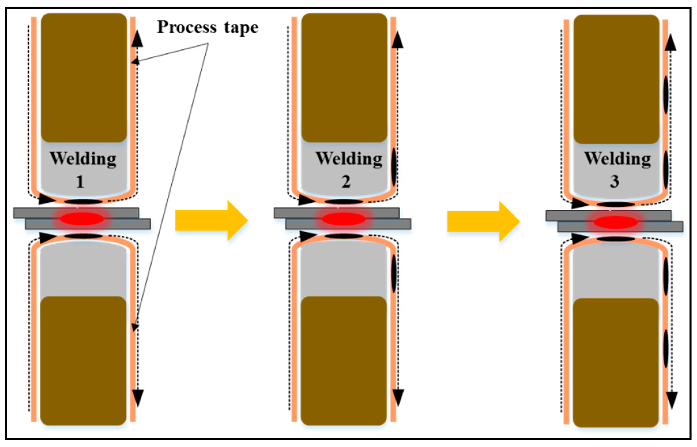
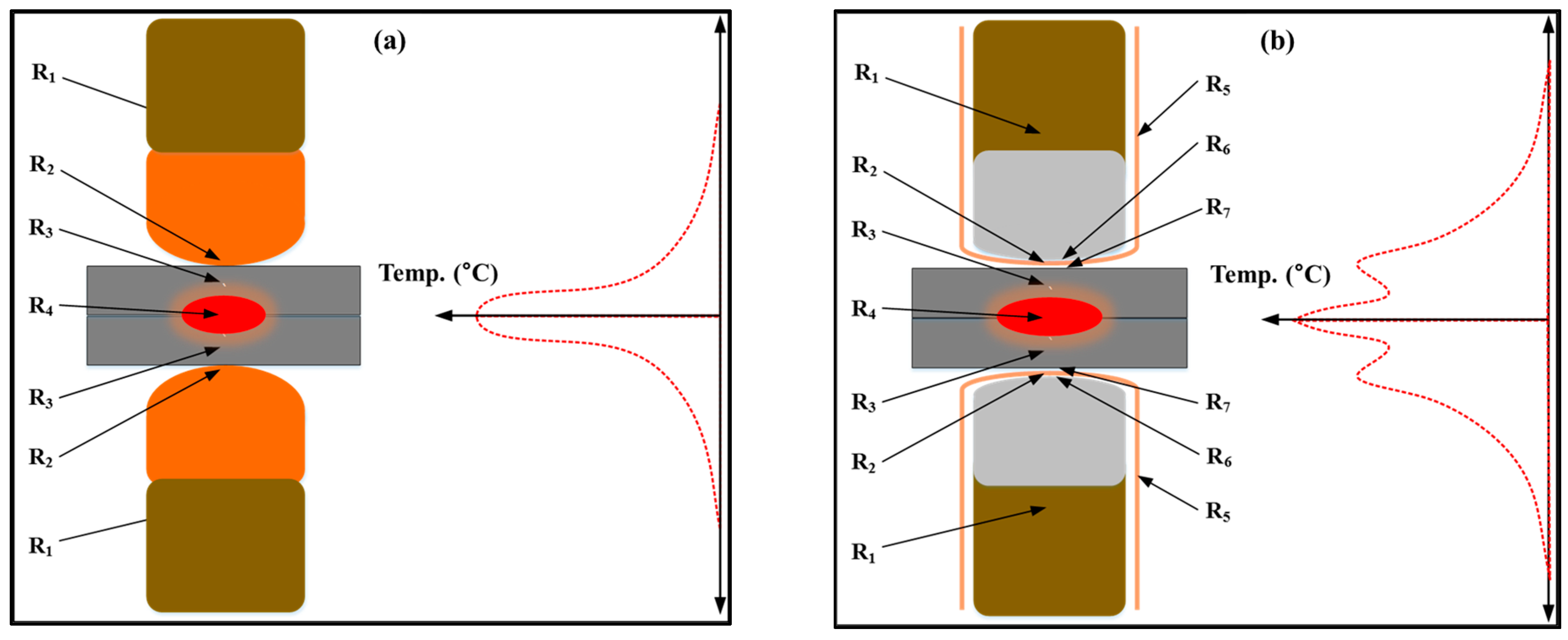
3.1. Effect of DeltaSpot Welding in Improving Weldability
3.2. Effects of DeltaSpot Welding Parameters
3.3. Weldability Evaluation with Respect to the Main Current Time and Force 1
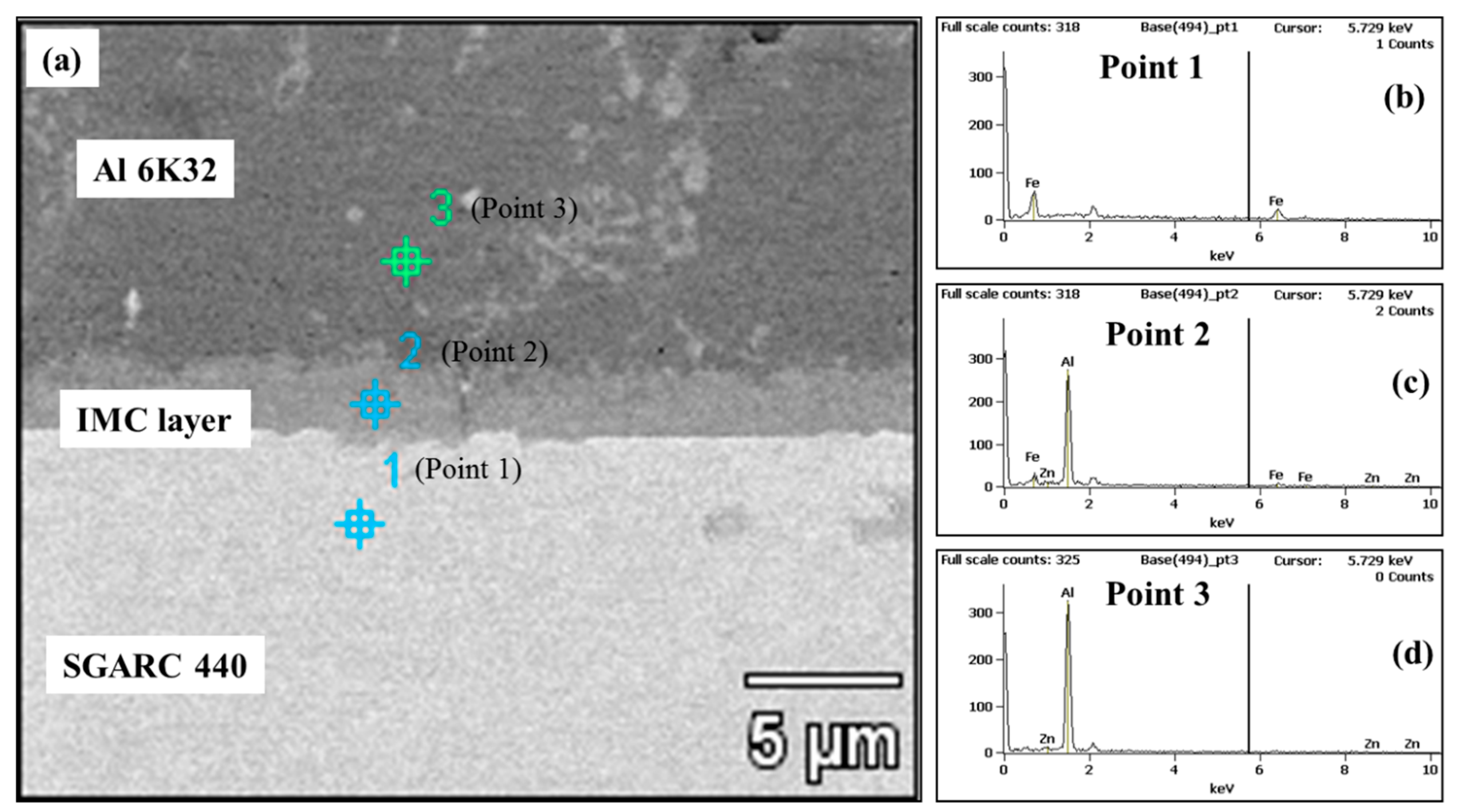
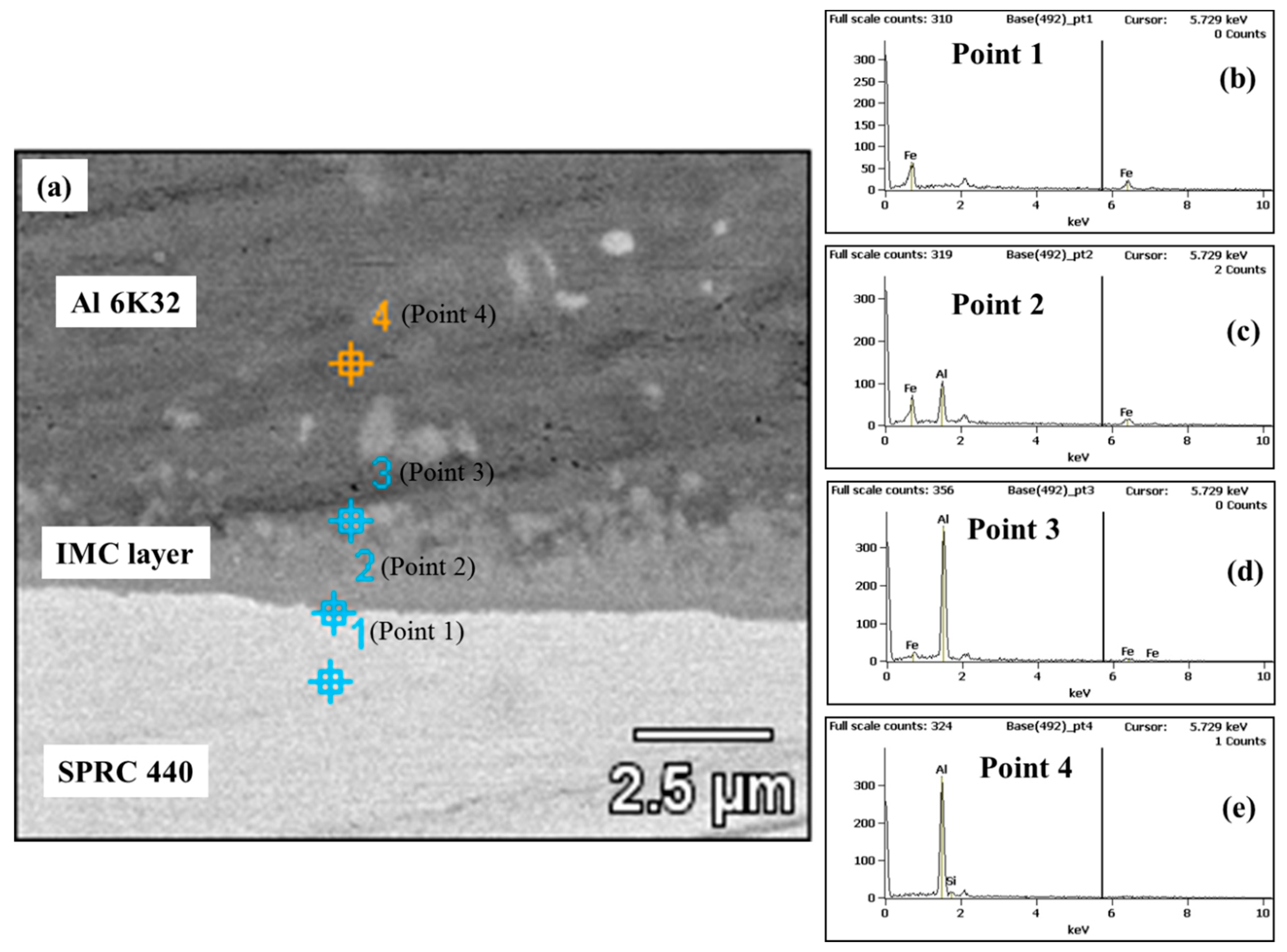
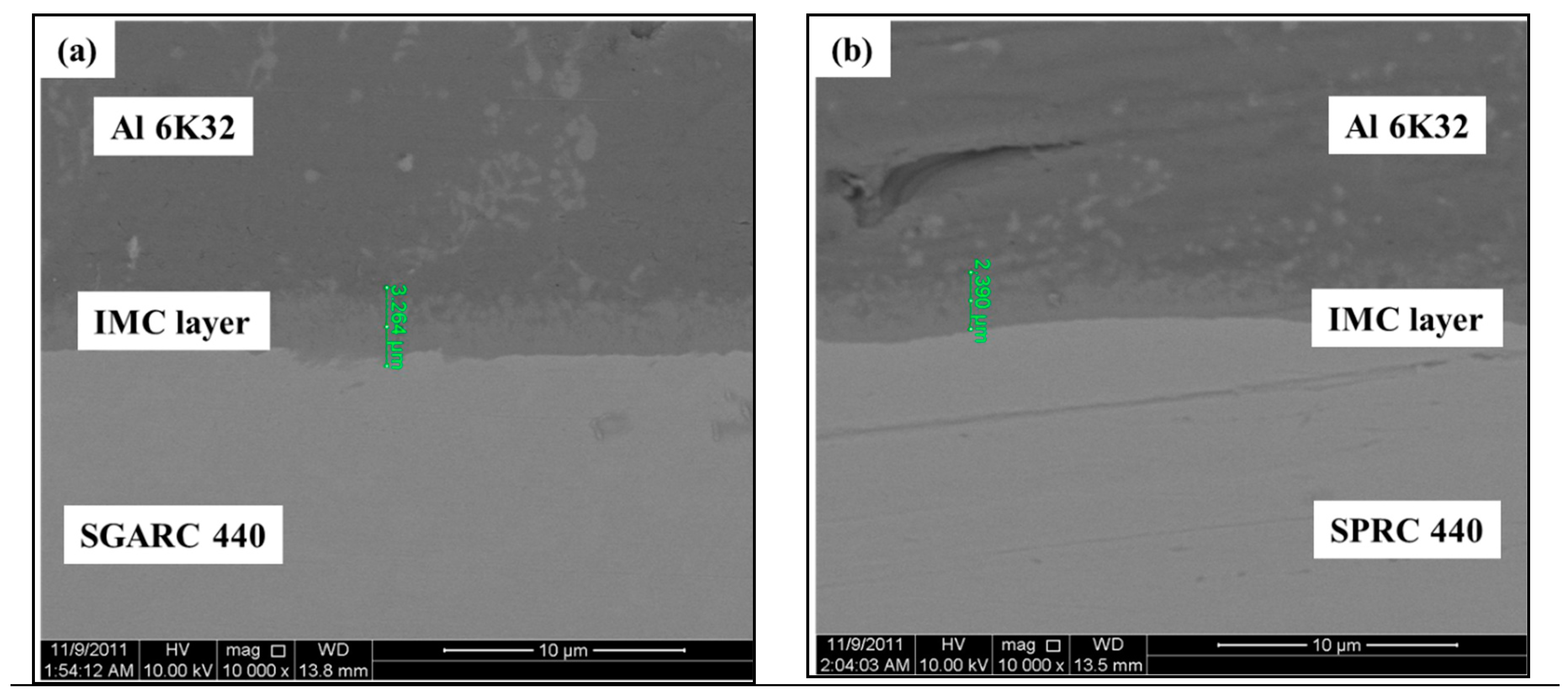
3.4. Evaluation of Coating-Dependent Dissimilar Metal Welding Characteristics
4. Conclusions
- (1)
- In the RSW of aluminum alloy to steel, lobe curve comparison verified the superiority of DeltaSpot welding to inverter DC spot welding in terms of the acceptable weld zone and weld stability owing to the effects of the process tape.
- (2)
- The optimum values of six DeltaSpot welding process parameters were derived from the analysis results for the welding characteristics of eight process parameters selected based on the results of an earlier study on the RSW of an aluminum alloy (Al 6K32) of the same thickness.
- (3)
- Weldability was evaluated as a function of the main current time, a main parameter along with the current level and force 1. The results of the lobe curve analysis revealed an overall tendency of the acceptable weld zone to move from the high- to low-current range, whereby no acceptable weld zone was formed in the range lower than 7 kA.
- (4)
- Weldability of aluminum alloy to different steel types was evaluated in order to enhance its applicability to different welding process conditions based on the steel types used in vehicle body assembly. The comparison of the weldability of aluminum alloy to zinc-coated and uncoated steel sheets revealed its weldability to uncoated steel sheets to be very low. This low weldability seems to be attributable to the fact that zinc melted onto the surface of the zinc-coated steel sheet forms a compound in the IMC layer, thus improving the bonding force. The difference in the zinc content in the IMC layer was verified by SEM-EDS analysis.
Author Contributions
Funding
Acknowledgments
Conflicts of Interest
References
- Ramazani, A.; Mukherjee, K.; Abdurakhmanov, A.; Abbasi, M.; Prahl, U. Characterization of microstructure and Mechanical Properties of Resistance spot welded DP600 steel. Metals 2015, 5, 1704–1716. [Google Scholar] [CrossRef]
- Huin, T.; Dancette, S.; Fabrègue, D.; Dupuy, T. Investigation of the failure of advanced high strength steels heterogeneous spot welds. Metals 2016, 6, 111. [Google Scholar] [CrossRef]
- Yu, J. Adaptive Resistance Spot Welding Process that Reduces the Shunting Effect for Automotive High-Strength Steels. Metals 2018, 8, 775. [Google Scholar] [CrossRef]
- Džupon, M.; Kaščák, Ľ.; Spišák, E.; Kubík, R.; Majerníková, J. Wear of Shaped Surfaces of PVD Coated Dies for Clinching. Metals 2017, 7, 515. [Google Scholar] [CrossRef]
- Kazdal Zeytin, H.; Ertek Emre, H.; Kaçar, R. Properties of resistance spot-welded TWIP steels. Metals 2017, 7, 14. [Google Scholar] [CrossRef]
- He, X.; Deng, C.; Zhang, X. Fretting behavior of SPR joining dissimilar sheets of titanium and copper alloys. Metals 2016, 6, 312. [Google Scholar] [CrossRef]
- Fridlyander, I.N.; Sister, V.G.; Grushko, O.E.; Berstenev, V.V.; Sheveleva, L.M.; Ivanova, L.A. Aluminum alloys: promising materials in the automotive industry. Met. Sci. Heat Treat. 2002, 44, 365–370. [Google Scholar] [CrossRef]
- Kim, Y.; Park, K.Y.; Lee, K.D. Development of Welding Technologies for Lightweight Vehicle. J. Weld. Join. 2011, 29, 1–3. [Google Scholar] [CrossRef]
- Chang, W.S.; Choi, K.Y.; Kim, S.H.; Kweon, Y.G. Some Aspects of Friction Stir Welding and Its Application Technologies. J. Weld. Join. 2001, 19, 7–15. [Google Scholar]
- Yeon, Y.M.; Lee, W.B.; Jung, S.B. Microstructures and Characteristics of Friction-Stir-Welded Joints in Aluminum Alloys. J. Weld. Join. 2001, 19, 584–590. [Google Scholar]
- Kim, H.T.; Kil, S.C. High Efficient Welding Technology of the Car Bodies. J. Weld. Join. 2016, 34, 62–66. [Google Scholar] [CrossRef]
- Inaba, T.; Tokuda, K.; Yamashita, H.; Takebayashi, Y.; Minoura, T.; Sasabe, S. Wrought aluminum technologies for automobiles. Kobelco Technol. Rev. 2005, 26, 55–62. [Google Scholar]
- Barnes, T.A.; Pashby, I.R. Joining techniques for aluminium spaceframes used in automobiles: Part II—Adhesive bonding and mechanical fasteners. J. Mater. Process. Technol. 2000, 99, 72–79. [Google Scholar] [CrossRef]
- Yum, D.B.; Ko, J.B.; Choi, B.K.; Lee, S.G.; Kim, A.K. Evaluation of Resistance Spot Welding Weldability of Aluminum Alloy 5000 Series. Trans. Kor. Soc. Mach. Tool Eng. 2002, 11, 8–13. [Google Scholar]
- Cai, W.; Wang, P.C.; Yang, W. Assembly dimensional prediction for self-piercing riveted aluminum panels. Int. J. Mach. Tools Manuf. 2005, 45, 695–704. [Google Scholar] [CrossRef]
- Kim, J.Y.; Lee, C.J.; Lee, S.K.; Ko, D.C.; Kim, B.M. Effect of shape parameters of tool on improvement of joining strength in clinching. Trans. Mater. Process. 2009, 18, 392–400. [Google Scholar]
- Rao, H.M.; Kang, J.; Huff, G.; Avery, K. Structural Stress Method to Evaluate Fatigue Properties of Similar and Dissimilar Self-Piercing Riveted Joints. Metals 2019, 9, 359. [Google Scholar] [CrossRef]
- Peng, G.; Yan, Q.; Hu, J.; Chen, P.; Chen, Z.; Zhang, T. Effect of Forced Air Cooling on the Microstructures, Tensile Strength, and Hardness Distribution of Dissimilar Friction Stir Welded AA5A06-AA6061 Joints. Metals 2019, 9, 304. [Google Scholar] [CrossRef]
- Patel, V.; Li, W.; Wang, G.; Wang, F.; Vairis, A.; Niu, P. Friction Stir Welding of Dissimilar Aluminum Alloy Combinations: State-of-the-Art. Metals 2019, 9, 270. [Google Scholar] [CrossRef]
- Nakamura, T.; Obikawa, T.; Nishizaki, I.; Enomoto, M.; Fang, Z. Friction Stir Welding of Non-Heat-Treatable High-Strength Alloy 5083-O. Metals 2018, 8, 208. [Google Scholar] [CrossRef]
- Li, Z.; Hao, C.; Zhang, J.; Zhang, H. Effects of sheet surface conditions on electrode life in resistance welding aluminum. Weld. J. 2007, 86, 81s–89s. [Google Scholar]
- Park, S.H.; Park, B.C.; Kim, Y.G.; Beak, U.R. Fusion Zone Characteristics of Dissimilar Aluminum Alloys joining. In Proceedings of the KWS Conference, The Korean Welding and Joining Society, Jeonju, Korea, 15–16 November 2007; pp. 141–143. [Google Scholar]
- Cho, S.M. Resistance welding and resistance joining technology to Fe-base material of Al-alloy. J. Weld. Join. 2001, 19, 14–22. [Google Scholar]
- Rashid, M.; Fukumoto, S.; Medley, J.B.; Villafuerte, J.; Zhou, Y. Influence of lubricants on electrode life in resistance spot welding of aluminum alloys. Weld. J. 2007, 86, 62s–70s. [Google Scholar]
- Yeon, Y.M.; Lee, W.B.; Lee, C.Y.; Jung, S.B.; Song, K. Joint Characteristics of Spot Friction Stir Welded A 5052 Alloy Sheet. J. Weld. Join. 2006, 24, 71–76. [Google Scholar]
- Yeon, Y.M.; Lee, C.Y.; Lee, W.B.; Jung, S.B.; Chang, W.S. Spot friction stir welding and characteristics of joints in aluminum alloys. J. Weld. Join. 2005, 23, 16–20. [Google Scholar]
- Thornton, P.H.; Krause, A.R.; Davies, R.G. Aluminum spot weld. Weld. J. Res. Suppl. 1996, 75, 101s–108s. [Google Scholar]
- Sun, X.; Dong, P. Analysis of aluminum resistance spot welding processes using coupled finite element procedures. Weld. J. 2000, 79, 215s–221s. [Google Scholar]
- Senkara, J.; Zhang, H. Cracking in spot welding aluminum alloy AA5754. Weld. J. 2000, 79, 194s–201s. [Google Scholar]
- Browne, D.J.; Chandler, H.W.; Evans, J.T.; Wen, J. Computer simulation of resistance spot welding in aluminum: Part I. Weld. J. Res. Suppl. 1995, 74, 339s–344s. [Google Scholar]
- Browne, D.J.; Chandler, H.W.; Evans, J.T.; James, P.S.; Wen, J.; Newton, C.J. Computer simulation of resistance spot welding in aluminum: Part II. Weld. J. Res. Suppl. 1995, 74, 417s–422s. [Google Scholar]
- Qiu, R.; Iwamoto, C.; Satonaka, S. The influence of reaction layer on the strength of aluminum/steel joint welded by resistance spot welding. Mater. Charact. 2009, 60, 156–159. [Google Scholar] [CrossRef]
- Qiu, R.; Iwamoto, C.; Satonaka, S. Interfacial microstructure and strength of steel/aluminum alloy joints welded by resistance spot welding with cover plate. J. Mater. Process. Technol. 2009, 209, 4186–5193. [Google Scholar] [CrossRef]
- Mortazavi, S.N.; Marashi, P.; Pouranvari, M.; Masoumi, M. Investigation on joint strength of dissimilar resistance spot welds of aluminum alloy and low carbon steel. Adv. Mater. Res. 2011, 264–265, 384–389. [Google Scholar] [CrossRef]
- Yu, J.; Choi, Y.; Shim, J.; Cho, Y.; Rhee, S. A study on resistance spot welding for aluminum alloys with spooling process tapes. In Proceedings of the International Conference on Advances in Welding Science and Technology for Construction, Energy and Transportation, AWST, held in Conjunction with the 63rd Annual Assembly of the International Institute of Welding, IIW 2010, Istanbul, Turkey,, 15–16 July 2010; pp. 679–684. [Google Scholar]
- Yeom, J. A Study on Resistance Spot Welding of Aluminum Alloys Based on the Current and Electrode Force Characteristics Analysis. Master’s Thesis, Hanyang University, Seoul, Korea, 2007. [Google Scholar]
- Ikeuchi, K.; Yamamoto, N.; Takahashi, M.; Aritoshi, M. Effect of interfacial reaction layer on bond strength of friction-bonded joint of Al alloys to steel. Trans. JWRI 2005, 34, 1–10. [Google Scholar]


| Al 6K32 | Mg | Si | Fe | Cu | Mn | Cr | Zn | Ti |
| 0.02 | 1.0 | 0.13 | 0.01 | 0.07 | 0.01 | 0.01 | 0.01 | |
| SGARC 440 | Si | Cu | Mn | Cr | Ni | Mo | V | C |
| 0.14 | 0.1 | 1.4 | 0.1 | 0.1 | 0.05 | 0.01 | 0.09 |
| Base Metal | Process Tape | Tape Material | Heat Input from Outside |
|---|---|---|---|
| Al 6K32 | PT 3000 | CrNi | High |
| SGARC 440 | PT 1407 | Steel | Medium |
| Welding Conditions | Profiles of Welding Current and Electrode Force | |
|---|---|---|
| Current (kA) | 9, 11, 13 | 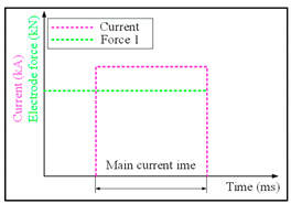 |
| Up slope time (ms) | 0 | |
| Main current time (ms) | 166, 332, 500 | |
| Down slope time (ms) | 0 | |
| Force 1 (kN) | 2 | |
| Force 2 (kN) | 0 | |
| Pre-force time (ms) | 0 | |
| Hold time (ms) | 0 | |
| Main Current Time (ms) | Item | Current Level (kA) | ||
|---|---|---|---|---|
| 9 | 11 | 13 | ||
| 166 | Fracture mode |  |  | 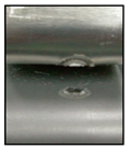 |
| Cross Section | 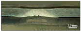 | 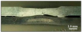 | 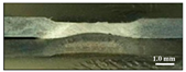 | |
| 332 | Fracture mode | 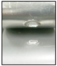 | 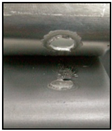 | 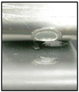 |
| Cross Section | 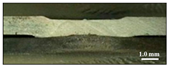 |  |  | |
| 500 | Fracture mode |  |  |  |
| Cross Section |  | 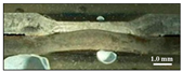 |  | |
| Main Current Time (ms) | Item | Current Level (kA) | ||
|---|---|---|---|---|
| 9 | 11 | 13 | ||
| 166 | Fracture mode | Interfacial | Interfacial | Interfacial |
| Expulsion | - | - | expulsion | |
| Nugget diameter (mm) | - | - | - | |
| TSS (kN) | 1.2 | 2.7 | 2.4 | |
| 332 | Fracture mode | Plug | Plug | Plug |
| Expulsion | - | expulsion | expulsion | |
| Nugget diameter (mm) | 3.8 | 4.6 | 6.5 | |
| TSS (kN) | 2.1 | 2.9 | 3.8 | |
| 500 | Fracture mode | Interfacial | Interfacial | Interfacial |
| Expulsion | - | expulsion | expulsion | |
| Nugget diameter (mm) | - | - | - | |
| TSS (kN) | 2.8 | 3.4 | 3.4 | |
| Main Current Time (ms) | Item | Current Level (kA) | ||
|---|---|---|---|---|
| 9 | 11 | 13 | ||
| 166 | Fracture shape |  |  |  |
| Cross Section | 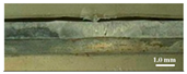 |  | 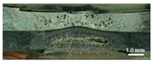 | |
| 332 | Fracture shape |  | 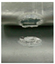 | 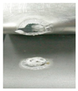 |
| Cross Section | 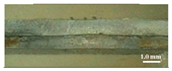 |  |  | |
| 500 | Fracture shape | 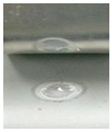 | 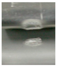 |  |
| Cross Section | 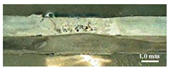 |  |  | |
| Main Current Time (ms) | Item | Current Level (kA) | ||
|---|---|---|---|---|
| 9 | 11 | 13 | ||
| 166 | Fracture mode | Interfacial | Interfacial | Interfacial |
| Expulsion | - | - | - | |
| Nugget diameter (mm) | - | - | - | |
| TSS (kN) | 1.2 | 1.9 | 5.2 | |
| 332 | Fracture mode | Plug | Plug | Plug |
| Expulsion | - | - | expulsion | |
| Nugget diameter (mm) | 7.4 | 7.2 | 7.5 | |
| TSS (kN) | 4.8 | 4.7 | 4.0 | |
| 500 | Fracture mode | Interfacial | Plug | Plug |
| Expulsion | expulsion | expulsion | expulsion | |
| Nugget diameter (mm) | - | 6.5 | 7.7 | |
| TSS (kN) | 2.5 | 4.6 | 4.5 | |
| Parameter | Level |
|---|---|
| Current (kA) | 10 |
| Up-slope time (ms) | 50 |
| Main current time (ms) | 300 |
| Down-slope time (ms) | 300 |
| Force 1 (kN) | 2 |
| Force 2 (kN) | 5 |
| Pre-force time (ms) | 0 |
| Hold time (ms) | 100 |
| Parameter | Level |
|---|---|
| Current (kA) | 10 (fixed) |
| Up-slope time (ms) | 0, 50, 100, 150 |
| Main current time (ms) | 200, 300, 400, 500 |
| Down-slope time (ms) | 0, 150, 300, 450 |
| Force 1 (kN) | 2, 3, 4, 5, |
| Force 2 (kN) | 5 (fixed) |
| Pre-force time (ms) | 50, 0, −50 |
| Hold time (ms) | 0, 50, 100, 150 |
| Parameter | Level | Expulsion | TSS (kN) | Fracture Mode |
|---|---|---|---|---|
| Up-slope time (ms) | 0 | X | 3.66 | Interfacial |
| 50 | X | 3.47 | Plug | |
| 100 | X | 3.23 | Plug | |
| 150 | X | 3.01 | Interfacial | |
| Main current time (ms) | 200 | X | 2.79 | Plug |
| 300 | X | 3.47 | Plug | |
| 400 | O | 3.53 | Plug | |
| 500 | O | 1.42 | Plug | |
| Down-slope time (ms) | 0 | X | 2.93 | Plug |
| 150 | X | 3.38 | Plug | |
| 300 | X | 3.47 | Plug | |
| 450 | X | 3.38 | Plug | |
| Force 1 (kN) | 2 | X | 3.47 | Plug |
| 3 | X | 2.39 | Plug | |
| 4 | X | 2.66 | Interfacial | |
| 5 | X | 2.41 | Interfacial | |
| Pre-force time (ms) | 50 | X | 2.85 | Interfacial |
| 0 | X | 3.47 | Plug | |
| –50 | X | 3.44 | Plug | |
| Hold time (ms) | 0 | X | 3.89 | Plug |
| 50 | X | 3.19 | Plug | |
| 100 | X | 3.47 | Plug | |
| 150 | X | 3.02 | Plug |
| Parameter | Level |
|---|---|
| Up-slope time (ms) | 50 |
| Main current time (ms) | 300 |
| Down-slope time (ms) | 300 |
| Force 1 (kN) | 2 |
| Force 2 (kN) | 5 |
| Pre-force time (ms) | 0 |
| Hold time (ms) | 100 |
| Parameter | Level |
|---|---|
| Current (kA) | 5–14 |
| Up-slope time (ms) | 50 |
| Main current time (ms) | 300, 400, 500 |
| Down-slope time (ms) | 300 |
| Force 1 (kN) | 1–4.5 |
| Force 2 (kN) | 5 |
| Pre-force time (ms) | 0 |
| Hold time (ms) | 100 |
| Current | |||||||||||
| Force 1 | 4.5 | - | - | - | - | - | 3167 | 3791 | 3279 | 3460 | 3975 |
| 4 | - | - | - | - | 2456 | 3167 | 3073 | 3132 | 3868 | 3051 | |
| 3.5 | - | - | - | 2074 | 2752 | 2863 | 3756 | 3213 | 3353 | - | |
| 3 | - | - | 2312 | 2317 | 2875 | 3144 | 3209 | 3065 | 3548 | - | |
| 2.5 | - | - | 2438 | 2831 | 3179 | 3684 | 3693 | 3025 | - | - | |
| 2 | - | 1349 | 2987 | 3784 | 3756 | 3467 | 4001 | - | - | - | |
| 1.5 | - | 2813 | 2961 | 3769 | 4295 | - | - | - | - | - | |
| 1 | - | 3052 | - | - | - | - | - | - | - | - | |
| 5 | 6 | 7 | 8 | 9 | 10 | 11 | 12 | 13 | 14 | ||
| Current | |||||||||||
| Force 1 | 4.5 | - | - | - | 2948 | 3203 | 3066 | 3237 | 3371 | 3440 | - |
| 4 | - | - | 2033 | 3286 | 2988 | 3194 | 3493 | 3469 | 3716 | - | |
| 3.5 | - | - | 2292 | 2221 | 3148 | 3229 | 3379 | - | - | - | |
| 3 | - | 2008 | 3234 | 3569 | 3408 | 3510 | 3529 | - | - | - | |
| 2.5 | - | 2241 | 3212 | 3662 | 3514 | - | - | - | - | - | |
| 2 | 2078 | 2093 | 3580 | 3469 | - | - | - | - | - | - | |
| 1.5 | 2448 | 2771 | 3586 | - | - | - | - | - | - | - | |
| 1 | 3018 | - | - | - | - | - | - | - | - | - | |
| 5 | 6 | 7 | 8 | 9 | 10 | 11 | 12 | 13 | 14 | ||
| Current | |||||||||||
| Force 1 | 4.5 | - | - | - | - | 2750 | 3374 | 3575 | 3317 | - | - |
| 4 | - | - | - | 2771 | 3031 | 3245 | 3386 | 3396 | - | - | |
| 3.5 | - | - | 2386 | 2923 | 3254 | 3371 | 3701 | 3957 | - | - | |
| 3 | - | - | 2023 | 2395 | 3293 | 3804 | 3711 | 4219 | - | - | |
| 2.5 | - | - | 2894 | 3321 | 3762 | 3467 | - | - | - | - | |
| 2 | - | 2705 | 3374 | 3504 | 3405 | - | - | - | - | - | |
| 1.5 | - | 2940 | 3228 | 3877 | - | - | - | - | - | - | |
| 1 | 537 | 3286 | - | - | - | - | - | - | - | - | |
| 5 | 6 | 7 | 8 | 9 | 10 | 11 | 12 | 13 | 14 | ||
| Current | |||||||||||
| Force 1 | 4.5 | - | - | - | 651 | 976 | 1625 | 237 | - | - | |
| 4 | - | - | - | 95 | 445 | 1786 | 1172 | 263 | - | - | |
| 3.5 | - | - | - | x | 739 | 1119 | 721 | 195 | - | - | |
| 3 | - | - | - | 344 | 1220 | 513 | 1426 | 1177 | - | - | |
| 2.5 | 415 | - | - | 389 | 1553 | 336 | 839 | - | - | - | |
| 2 | 561 | x | - | 799 | 1093 | 145 | 1256 | - | - | - | |
| 1.5 | 477 | x | x | - | - | - | - | - | - | - | |
| 1 | - | - | - | - | - | - | - | - | - | - | |
| 5 | 6 | 7 | 8 | 9 | 10 | 11 | 12 | 13 | 14 | ||
| Position | Element (Wt %) | ||
|---|---|---|---|
| Al-k | Fe-k | Zn-k | |
| Point 3 | 98.30 | - | 1.70 |
| Point 2 | 69.04 | 30.30 | 0.65 |
| Point 1 | - | 100.00 | - |
| Position | Element (Wt %) | ||
|---|---|---|---|
| Al-k | Si-k | Fe-k | |
| Point 4 | 97.17 | 2.83 | - |
| Point 3 | 74.36 | - | 25.64 |
| Point 2 | 20.44 | - | 79.56 |
| Point 1 | - | - | 100.00 |
© 2019 by the authors. Licensee MDPI, Basel, Switzerland. This article is an open access article distributed under the terms and conditions of the Creative Commons Attribution (CC BY) license (http://creativecommons.org/licenses/by/4.0/).
Share and Cite
Shin, S.; Park, D.-J.; Yu, J.; Rhee, S. Resistance Spot Welding of Aluminum Alloy and Carbon Steel with Spooling Process Tapes. Metals 2019, 9, 410. https://doi.org/10.3390/met9040410
Shin S, Park D-J, Yu J, Rhee S. Resistance Spot Welding of Aluminum Alloy and Carbon Steel with Spooling Process Tapes. Metals. 2019; 9(4):410. https://doi.org/10.3390/met9040410
Chicago/Turabian StyleShin, Seungmin, Dae-Jin Park, Jiyoung Yu, and Sehun Rhee. 2019. "Resistance Spot Welding of Aluminum Alloy and Carbon Steel with Spooling Process Tapes" Metals 9, no. 4: 410. https://doi.org/10.3390/met9040410
APA StyleShin, S., Park, D.-J., Yu, J., & Rhee, S. (2019). Resistance Spot Welding of Aluminum Alloy and Carbon Steel with Spooling Process Tapes. Metals, 9(4), 410. https://doi.org/10.3390/met9040410