
Geometric Anatomy Basis for Safe and Effective Focal Ablation of Prostate Cancer by Irreversible Electroporation (IRE)


 ,
, 
Abstract
1. Introduction
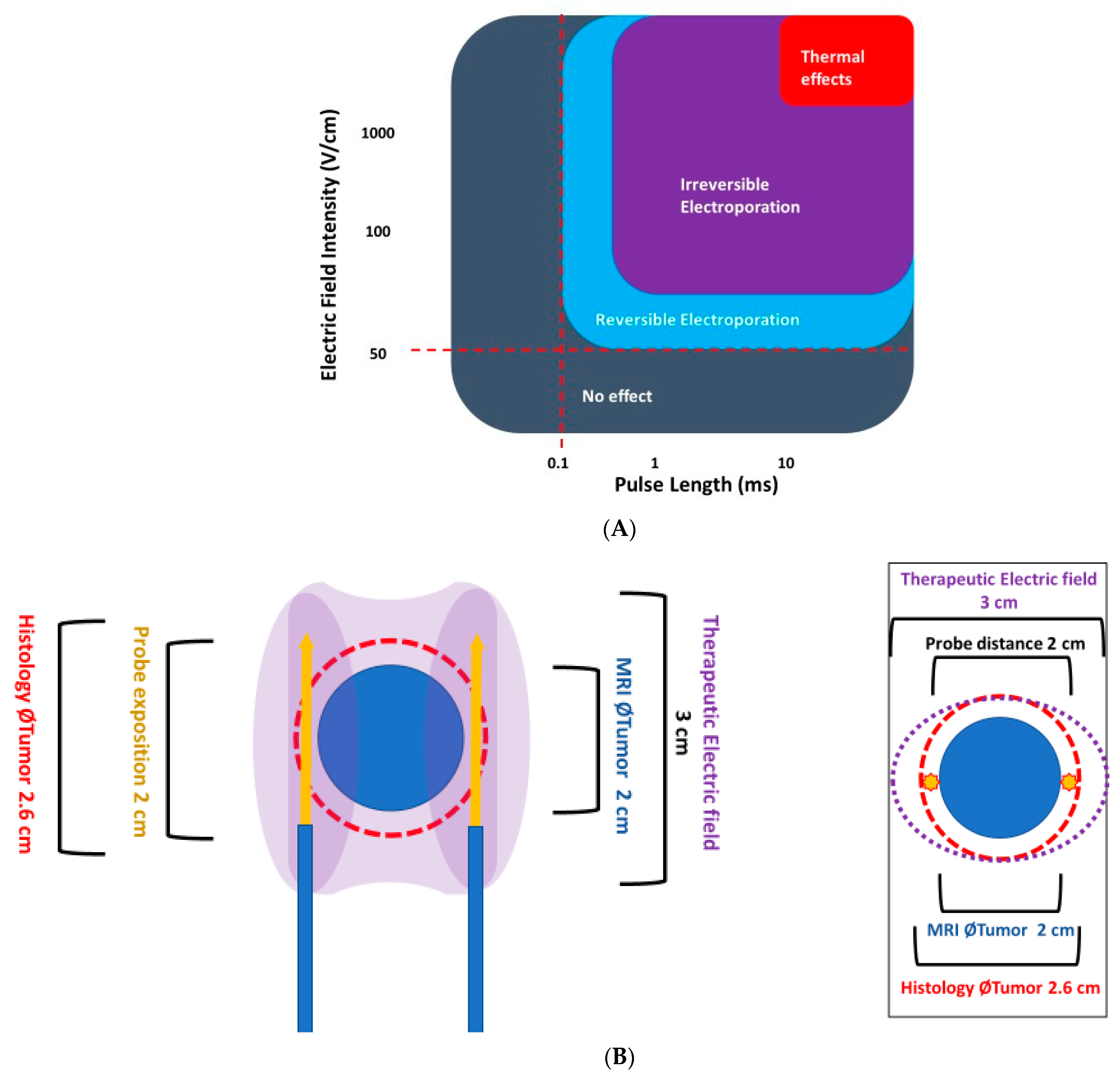
2. How IRE Works
- The shape of the area bounded by the needles (probes) should completely cover the tumour area and a safety margin (IRE ablation zone) of at least 0.5 cm.
- The therapeutic electric field halo covers the uncertainty between the mpMRI image and the pathological edge of cancer, which is estimated at around 1 cm to cover 100% of tumour margins.
- The recommended distance between two probes should be less than 2.5 cm and over 0.8 cm.
- The probes should be as far away as possible from sensitive anatomical structures such as the rectal wall or neurovascular bundles.
- The exposed part of the needle should be between 1.0 and 2.5 cm in length and adapted to the curvature of the edge of the prostate gland, to reduce the impact of the electric field outside of the prostate.
- The axis of the needles, particularly their active tip length, must be strictly parallel.
3. Relevant Sections
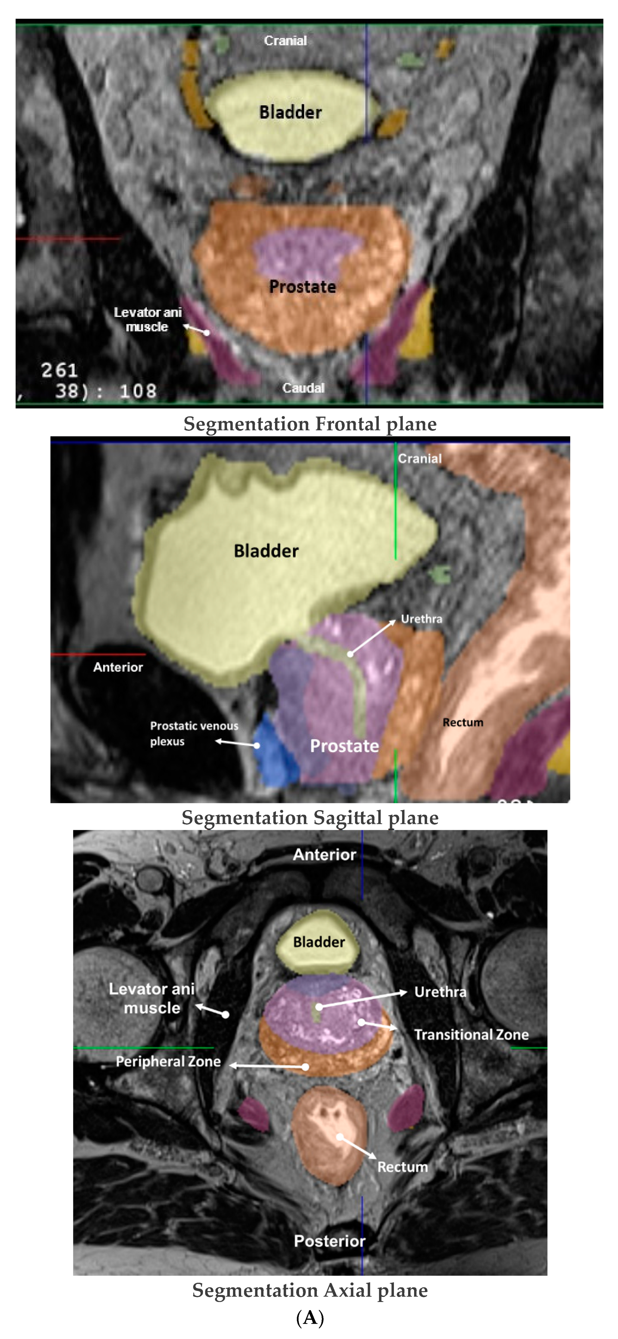
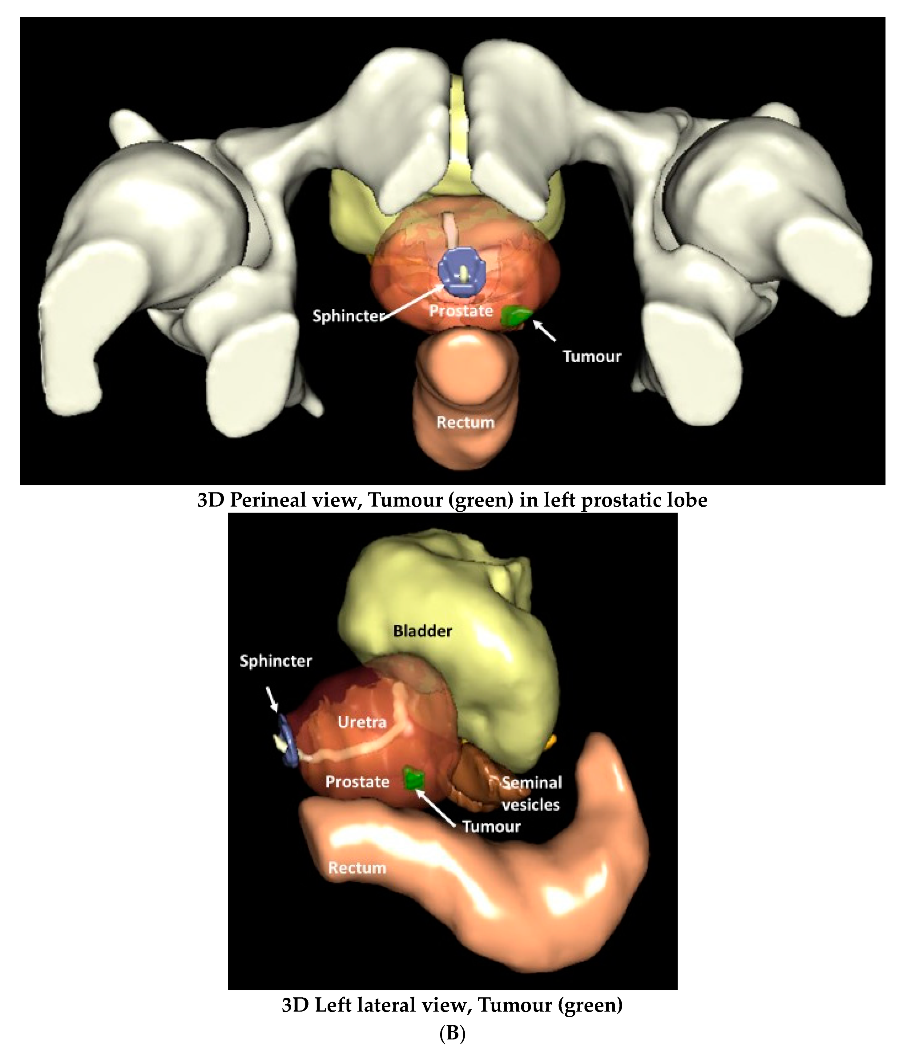
3.1. Surgical and MRI of Prostate Anatomy in the Context of IRE
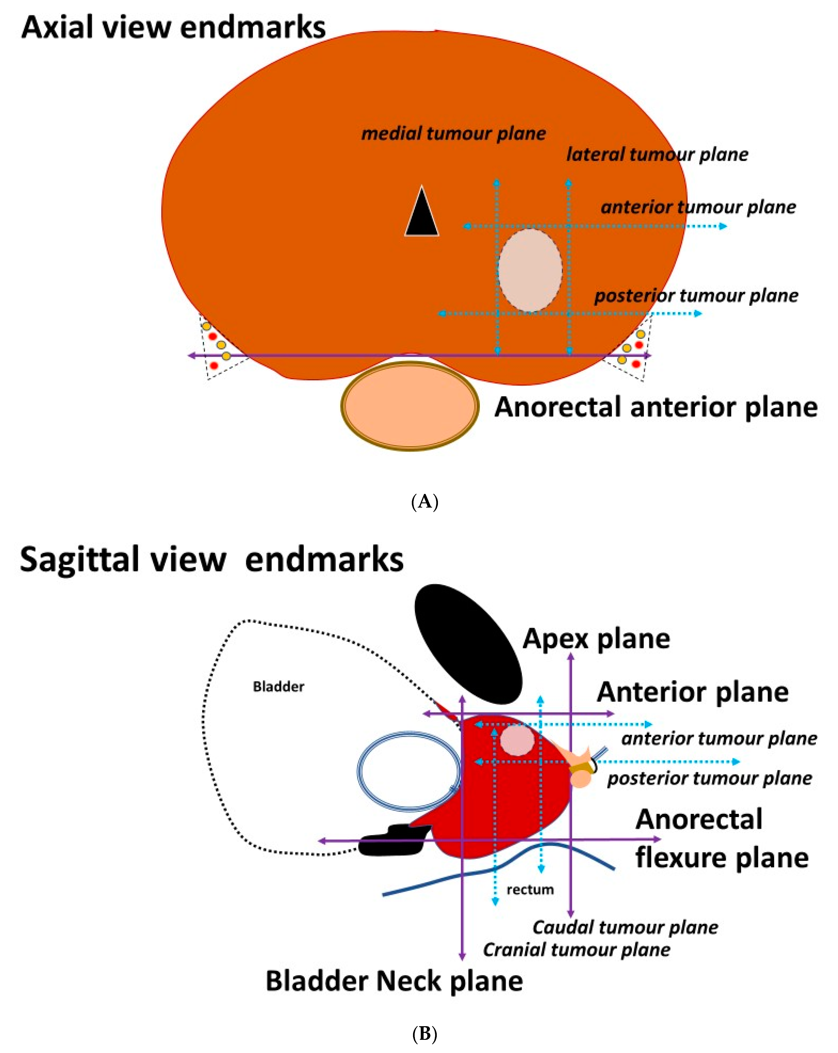
3.2. Placement of the Needles on the Axial Prostatic View
3.3. Placement of the Needles on the Sagittal View
4. Conclusions and Future Directions
Supplementary Materials
Funding
Institutional Review Board Statement
Informed Consent Statement
Conflicts of Interest
References
- Wang, L.; Lu, B.; He, M.; Wang, Y.; Wang, Z.; Du, L. Prostate Cancer Incidence and Mortality: Global Status and Temporal Trends in 89 Countries from 2000 to 2019. Front. Public Health 2022, 10, 811044. [Google Scholar] [CrossRef] [PubMed]
- Hamdy, F.C.; Donovan, J.L.; Lane, J.A.; Metcalfe, C.; Davis, M.; Turner, E.L.; Martin, R.M.; Young, G.J.; Walsh, E.I.; Bryant, R.J.; et al. Fifteen-Year Outcomes after Monitoring, Surgery, or Radiotherapy for Prostate Cancer. N. Engl. J. Med. 2023, 388, 1547–1558. [Google Scholar] [CrossRef] [PubMed]
- van der Poel, H.; Klotz, L.; Andriole, G.; Azzouzi, A.-R.; Bjartell, A.; Cussenot, O.; Hamdy, F.; Graefen, M.; Palma, P.; Rivera, A.R.; et al. Role of active surveillance and focal therapy in low- and intermediate-risk prostate cancers. World J. Urol. 2015, 33, 907–916. [Google Scholar] [CrossRef] [PubMed]
- Lunelli, L.; Cussenot, O.; de la Rosette, J. Irreversible Electroporation (IRE) for Prostate Cancer. In Interventional Urology; Springer: Cham, Switzerland, 2021; pp. 241–247. [Google Scholar]
- Aycock, K.N.; Davalos, R.V. Irreversible Electroporation: Background, Theory, and Review of Recent Developments in Clinical Oncology. Bioelectricity 2019, 1, 214–234. [Google Scholar] [CrossRef] [PubMed]
- Geboers, B.; Scheffer, H.J.; Graybill, P.M.; Ruarus, A.H.; Nieuwenhuizen, S.; Puijk, R.S.; Tol, P.M.V.D.; Davalos, R.V.; Rubinsky, B.; De Gruijl, T.D.; et al. High-Voltage Electrical Pulses in Oncology: Irreversible Electroporation, Electrochemotherapy, Gene Electrotransfer, Electrofusion, and Electroimmunotherapy. Radiology 2020, 295, 254–272. [Google Scholar] [CrossRef] [PubMed]
- Wendler, J.J.; Fischbach, K.; Ricke, J.; Jürgens, J.; Fischbach, F.; Köllermann, J.; Porsch, M.; Baumunk, D.; Schostak, M.; Liehr, U.-B.; et al. Irreversible Electroporation (IRE): Standardization of Terminology and Reporting Criteria for Analysis and Comparison. Pol. J. Radiol. 2016, 81, 54–64. [Google Scholar] [CrossRef] [PubMed]
- Hoeh, B.; Wenzel, M.; Hohenhorst, L.; Köllermann, J.; Graefen, M.; Haese, A.; Tilki, D.; Walz, J.; Kosiba, M.; Becker, A.; et al. Anatomical Fundamentals and Current Surgical Knowledge of Prostate Anatomy Related to Functional and Oncological Outcomes for Robotic-Assisted Radical Prostatectomy. Front. Surg. 2022, 8, 825183. [Google Scholar] [CrossRef] [PubMed]
- Lee, S.E.; Byun, S.-S.; Lee, H.J.; Song, S.H.; Chang, I.H.; Kim, Y.J.; Gill, M.C.; Hong, S.K. Impact of variations in prostatic apex shape on early recovery of urinary continence after radical retropubic prostatectomy. Urology 2006, 68, 137–141. [Google Scholar] [CrossRef] [PubMed]
- Sanford, T.H.; Harmon, S.A.; Kesani, D.; Gurram, S.; Gupta, N.; Mehralivand, S.; Sackett, J.; Wiener, S.; Wood, B.J.; Xu, S.; et al. Quantitative Characterization of the Prostatic Urethra Using MRI: Implications for Lower Urinary Tract Symptoms in Patients with Benign Prostatic Hyperplasia. Acad. Radiol. 2021, 28, 664–670. [Google Scholar] [CrossRef] [PubMed]
- McNeal, J.E. Regional Morphology and Pathology of The Prostate. Am. J. Clin. Pathol. 1968, 49, 347–357. [Google Scholar] [CrossRef] [PubMed]
- Wu, C.; Montagne, S.; Hamzaoui, D.; Ayache, N.; Delingette, H.; Renard-Penna, R. Automatic segmentation of prostate zonal anatomy on MRI: A systematic review of the literature. Insights Into Imaging 2022, 13, 202. [Google Scholar] [CrossRef] [PubMed]
- Laschkar, S.; Montagne, S.; De Kerviler, E.; Roupret, M.; Lucidarme, O.; Cussenot, O.; Penna, R.R. Zonal anatomy of the prostate using magnetic resonance imaging, morphometrics, and radiomic features: Impact of age-related changes. Br. J. Radiol. 2022, 95, 20210156. [Google Scholar] [CrossRef] [PubMed]
- Rusu, M.; Shao, W.; Kunder, C.A.; Wang, J.B.; Soerensen, S.J.C.; Teslovich, N.C.; Sood, R.R.; Chen, L.C.; Fan, R.E.; Ghanouni, P.; et al. Registration of presurgical MRI and histopathology images from radical prostatectomy via RAPSODI. Med. Phys. 2020, 47, 4177–4188. [Google Scholar] [CrossRef] [PubMed]
- Reynolds, H.M.; Williams, S.; Zhang, A.; Chakravorty, R.; Rawlinson, D.; Ong, C.S.; Esteva, M.; Mitchell, C.; Parameswaran, B.; Finnegan, M.; et al. Development of a registration framework to validate MRI with histology for prostate focal therapy. Med. Phys. 2015, 42, 7078–7089. [Google Scholar] [CrossRef] [PubMed]
- Le Nobin, J.; Rosenkrantz, A.B.; Villers, A.; Orczyk, C.; Deng, F.-M.; Melamed, J.; Mikheev, A.; Rusinek, H.; Taneja, S.S. Image Guided Focal Therapy for Magnetic Resonance Imaging Visible Prostate Cancer: Defining a 3-Dimensional Treatment Margin Based on Magnetic Resonance Imaging Histology Co-Registration Analysis. J. Urol. 2015, 194, 364–370. [Google Scholar] [CrossRef] [PubMed]
- Nickfarjam, A.; Firoozabadi, S.M.P. Parametric study of irreversible electroporation with different needle electrodes: Electrical and thermal analysis. Int. J. Hyperth. 2014, 30, 335–347. [Google Scholar] [CrossRef] [PubMed]
- Hogenes, A.M.; Overduin, C.G.; Slump, C.H.; van Laarhoven, C.J.H.M.; Fütterer, J.J.; Broek, R.P.G.T.; Stommel, M.W.J. The Influence of Irreversible Electroporation Parameters on the Size of the Ablation Zone and Thermal Effects: A Systematic Review. Technol. Cancer Res. Treat. 2023, 22, 15330338221125003. [Google Scholar] [CrossRef] [PubMed]
- Mottet, N.; van den Bergh, R.C.N.; Briers, E.; Van den Broeck, T.; Cumberbatch, M.G.; De Santis, M.; Fanti, S.; Fossati, N.; Gandaglia, G.; Gillessen, S.; et al. EAU-EANM-ESTRO-ESUR-SIOG Guidelines on Prostate Cancer-2020 Update. Part 1: Screening, Diagnosis, and Local Treatment with Curative Intent. Eur Urol. 2021, 79, 243–262. [Google Scholar]
- Ayerra Perez, H.; Barba Abad, J.F.; Extramiana Cameno, J. An Update on Focal Therapy for Prostate Cancer. Clin. Genitourin. Cancer, 2023; in press. [Google Scholar] [CrossRef]


Disclaimer/Publisher’s Note: The statements, opinions and data contained in all publications are solely those of the individual author(s) and contributor(s) and not of MDPI and/or the editor(s). MDPI and/or the editor(s) disclaim responsibility for any injury to people or property resulting from any ideas, methods, instructions or products referred to in the content. |
© 2023 by the authors. Licensee MDPI, Basel, Switzerland. This article is an open access article distributed under the terms and conditions of the Creative Commons Attribution (CC BY) license (https://creativecommons.org/licenses/by/4.0/).
Share and Cite
Cussenot, O.; Macpherson, R.; Leslie, T.; Lunelli, L.; Marra, G.; Laniado, M.; Hamdy, F.C.; Bryant, R.J. Geometric Anatomy Basis for Safe and Effective Focal Ablation of Prostate Cancer by Irreversible Electroporation (IRE). Anatomia 2023, 2, 232-242. https://doi.org/10.3390/anatomia2030021
Cussenot O, Macpherson R, Leslie T, Lunelli L, Marra G, Laniado M, Hamdy FC, Bryant RJ. Geometric Anatomy Basis for Safe and Effective Focal Ablation of Prostate Cancer by Irreversible Electroporation (IRE). Anatomia. 2023; 2(3):232-242. https://doi.org/10.3390/anatomia2030021
Chicago/Turabian StyleCussenot, Olivier, Ruth Macpherson, Tom Leslie, Luca Lunelli, Giancarlo Marra, Marc Laniado, Freddie C. Hamdy, and Richard J. Bryant. 2023. "Geometric Anatomy Basis for Safe and Effective Focal Ablation of Prostate Cancer by Irreversible Electroporation (IRE)" Anatomia 2, no. 3: 232-242. https://doi.org/10.3390/anatomia2030021
APA StyleCussenot, O., Macpherson, R., Leslie, T., Lunelli, L., Marra, G., Laniado, M., Hamdy, F. C., & Bryant, R. J. (2023). Geometric Anatomy Basis for Safe and Effective Focal Ablation of Prostate Cancer by Irreversible Electroporation (IRE). Anatomia, 2(3), 232-242. https://doi.org/10.3390/anatomia2030021