Article

A Model-Based Method Applying Sliding Mode Methodology for SynRM Sensorless Control

by
Vasilios C. Ilioudis
Department of Industrial Engineering and Management, International Hellenic University (IHU), 57400 Thessaloniki, Greece
Magnetism 2025, 5(1), 4; https://doi.org/10.3390/magnetism5010004
Submission received: 9 October 2024 / Revised: 29 December 2024 / Accepted: 21 January 2025 / Published: 4 February 2025

Abstract

:
In this paper, a new sensorless approach is proposed to address the speed and position estimation of the Synchronous Reluctance Machine (SynRM). The design of the sensorless control algorithm is developed on the basis of the modified SynRM mathematical model employing a simple sliding mode observer (SMO) and a modified EMF observer that are connected in series. All variables of the modified SynRM model are expressed in the arbitrary rotating frame, which is the so-called estimated γδ reference frame. The derived modified rotor flux terms contain angle error information in the form of trigonometric functions. Initially, the modified rotor flux is expressed as a function of saliency and the stator current id, including the angular deviation between the dq and γδ reference frames, which are rotating at synchronous and estimated speeds, respectively. A suitably designed SMO is utilized to estimate the modified stator flux components in the γδ reference frame. Once the SMO operates in sliding mode, the derived equivalent control inputs of the flux/current observer are used to obtain the required angular position and speed information of rotor by means of the modified EMF and Speed/Position observer. Only measures of stator voltages and currents are required for the speed and position estimation. In addition, Lyapunov Candidate Functions (LCFs) have been applied to determine the sliding mode existence conditions and the gains of the modified EMF observer. The SynRM observer–controller system is tested and evaluated in a wide speed range, even at very low speeds, in the presence of torque load disturbances. Simulation results demonstrate the overall efficacy and robustness of the proposed sensorless approach. Moreover, simulation tests verify the fast convergence and high performance of the modified EMF/speed/angle observer.

1. Introduction

In recent decades, a continuously increasing interest has been established in efficient energy conversion, considering the design and control of electrical machines. Among them, the Synchronous Reluctance Machine (SynRM) has been proposed as a promising and potentially an alternative solution for applications that require high performance [1]. Conventionally, this type of electrical machine is used in a plethora of applications where fast dynamic response and high efficiency are needed across a wide range of speeds. SynRM is characterized by the absence of permanent magnets within the rotor, while the torque produced is due to the inherent different reluctance paths in the rotor. SynRM has been introduced as a new general-purpose electrical machine for variable-speed drives [1,2,3]. Also, the Permanent Magnet Assisted Synchronous Reluctance Machine (PMASynRM) is similar to SynRM, with permanent magnets inserted into the rotor. This specific design of SynRM is very significant for applications where high torque density and fault-tolerant property are needed [4,5,6]. Although the Permanent Magnet Synchronous Machine (PMSM) is able to generate high power, the design of SynRM is simple and allows for achieving high efficiency and energy saving in variable-speed applications [7,8].
In the high-performance control strategies applied in SynRMs, such as those based on field-oriented control (FOC), the precise knowledge of rotor angular position and speed is required to control the SynRM during the electromechanical power conversion. The SynRM speed control in FOC is almost the same as in other AC machines, where the current component id is used to maintain the required flux and the current component iq controls the produced torque (see Figure 1). Specifically, the FOC algorithm can achieve the desired response by adjusting the stator flux and torque. This can be attained by directly controlling both the stator current components in the dq synchronous rotating frame. In this manner, FOC-based methods allow good performance to be obtained over an extended speed range, despite torque changes. Essentially, the stator field is effectively controlled, utilizing the accurate rotor angular position, while the control of the produced torque is based on the reluctance principle of SynRM. Particularly, the rotor angle knowledge allows keeping the rotor rotated in synchronization with the stator magnetic field [9]. Conventionally, rotor angular position is obtained through sensors, such as absolute digital encoders or magnetic resolvers, which are fixed on the SynRM rotor shaft. However, the rotor angular position sensors are sensitive to inherent electromagnetic noise, and their measurement accuracy is limited to a determined temperature range. In addition, for most applications, the usage of position-tracking devices normally downgrades the control reliability introducing various drawbacks, such as the installation complexity of the drive system, the increment of total rotor inertia, and hardware cost. Furthermore, the usage of these position measurement devices, either encoders or resolvers, decreases the reliability of the SynRM drive system. As opposed to SynRM electromechanical sensors, sensorless-based methods may enhance the robustness and the reliability of SynRM control, while they reduce the noise sensitivity of the overall drive system [9,10,11].
Numerous sensorless methods have been proposed to address the issues associated with position sensors. Nevertheless, these methods are predominantly required in high-cost applications or electrically hostile environments. In the literature, the proposed sensorless approaches are classified into two main strategies: Fundamental Excitation and the Saliency and Signal Injection [12,13,14,15,16]. In the fundamental excitation strategy, position estimation is based on the design of proper state observers, while only the measured fundamental excitation variables are used, e.g., stator voltages and currents. Typically, the estimations of rotor position and speed are obtained by meticulously following the back electromotive force (back-EMF or BEMF) or magnetic flux [17,18,19,20]. Back-EMF-based methods are capable of providing high accuracy estimates of speed and position when applied in the middle- and high-speed ranges [21,22]. Nevertheless, the back-EMF-based estimations tend to be unreliable at low speed and standstill operation, since the amplitude of the back-EMF is directly proportional to electrical speed. As a result, the observed back-EMF is becoming comparable to noise and too small to be precisely tracked at a low-speed range [14,23]. Additionally, the Extended Kalman filters (EKF) have been proven effective in estimating both speed and position, taking into account the random noise distributions [24].
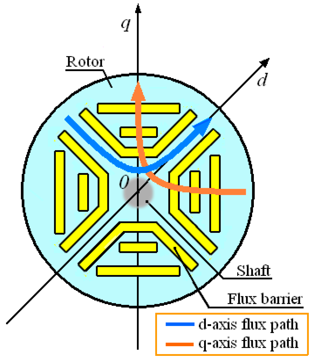
Apart from the previously referred sensorless approaches, the angular position of the rotor can also be effectively detected by applying Phase Locked Loop (PLL)-based observers [25,26]. In the techniques mentioned above, an open-loop control may be required before applying the sensorless control at the initial stage of starting SynRM. Considering the saliency and signal injection techniques, their estimation algorithms are developed on the basis of the spatial saliency tracking. In this particular sensorless strategy, high-frequency voltage or current signals are injected into SynRM stator windings and the current response is used to estimate the rotor position. SynRM operation depends on the inherent magnetic saliency, which is due to the rotor’s physical structure (see Figure 2) [27,28,29,30]. This property implies that the SynRM inductance depends on the rotor’s angular position. Employing the SynRM magnetic saliency methods allows for accurate estimation of both rotor angular speed and position at low speeds, even at zero-speed operation [31,32,33,34,35,36,37,38]. However, high frequency pulsations may be encountered due to HF-injected signals. Although many researchers have addressed saliency-based sensorless control, the cross-coupling effect has been considered negligible or omitted for simplicity reasons in some research works. Also, an additional issue of this type of sensorless control is that the existence of saturation could decrease or even eliminate the SynRM saliency [39,40].
Regarding the salient synchronous machines, e.g., IPM and SynRM, the sensorless methods that use back-EMF and flux mathematical models can attain more accurate estimations of the rotor angular position at middle and high speeds. Conversely, sensorless methods based on saliency tracking through HF signal injection perform more efficiently when applied at low, and even at zero, speeds. In addition, it is possible to change the applied sensorless method from the saliency tracking to the back-EMF-based one during the transition from low- to high-speed ranges and vice versa. Recently, the connection and improvement of both fundamental excitation and saliency tracking methods have been more widely investigated. Particularly noteworthy is the continuously increasing interest in research, with an emphasis on the sensorless control across a broad range of speeds. In many sensorless techniques, the implemented estimation algorithms of rotor position rely on the PMSM or SynRM mathematical models, which apply transformations to the modified or extended back-EMF in an estimated reference frame. Furthermore, some of these techniques aim to modify a salient (asymmetric) PMSM (IPM) or SynRM model into a non-salient (symmetric) but equivalent one through variable transformations [18,41,42]. Nevertheless, the accurateness of position estimation is significantly impacted by the precision of the SynRM mathematical model and the assumptions made. In a similar way, some of the proposed methods are based on the concept of the active flux trying to reduce the dynamic errors while expanding the operating speed range. These methods could be applied in the sensorless control of PMSM, SynRM, and IM, while the observer design seems to be similar to these AC machines [43,44]. Among the proposals for sensorless approaches, angle and speed estimation algorithms designed on the basis of Sliding Mode Observers (SMO) are very effective and robust, even when there are external disturbances and model uncertainties [45,46,47,48,49].
This paper focuses primarily on a SynRM sensorless method that is based on a modified SynRM model, with the objective of minimizing model approximations and operating in a broad speed range [42]. Also, the proposed modified SynRM model and the observer scheme are considered in the present study, expressing both to the estimated rotating frame. Particularly, the total observer scheme consists of a modified current and flux SMO connected in cascade mode with a modified EMF observer. A simple first-order SMO is developed for current/flux estimation, employing the equivalent control methodology. The equivalent inputs of the current/flux SMO are also used as inputs in the modified EMF observer to derive accurate estimates of both rotor speed and position. Essentially, the modified EMF observer effectively contributes to the extraction of the rotor position information contained in the equivalent control inputs. Regarding the overall drive system stability, the estimated currents/fluxes of SMO rapidly converge towards the real ones in finite time. As a consequence, the resulting angle and speed differences between the γδ and dq rotating reference frames are becoming extremely small, almost zero [42,45,46,47,48]. All real and estimated variables of SynRM are expressed in the reference system, while only stator voltages and currents are required in SMO. The derived equivalent control inputs are employed in the modified EMF observer to estimate speed and position.
The remainder of the paper is structured as follows. In Section 2, the modified SynRM model is analyzed and presented in both reference frames, dq and γδ, focusing on the rotor magnetic saliency and inductance matrix. The design of flux/current SMO is analyzed in Section 3, including the observer convergence and stability criteria in the sense of Lyapunov. In addition, the design of modified EMF observer is described in Section 4, on the basis of the equivalent control inputs, while a Lyapunov Candidate Function (LCF) is used to examine the observer’s stability. Furthermore, the simulation set-up, the results, and their evaluation are presented in Section 5 for several speeds and external torque scenarios, while the presented work is discussed and concluded in Section 6 and Section 7, respectively.

2. Analysis of the Modified SynRM Model in the γδ-Estimated Rotating Frame

2.1. Voltage and Flux/Current Model of SynRM, and Modified Rotor Flux in the dq Synchronous Rotating Frame

The mathematical model of SynRM is dependent upon its type, its geometric characteristics, and the reference system employed. In the present study, it is supposed that sinusoidal EMF is induced in the stator windings, while the inductances of SynRM in dq are considered such that Ld is greater than Lq, i.e., (Ld/Lq) > 1. The SynRM voltage and flux/current models are described in the synchronous rotating frame by the following equations.
u d q = r s i d q + ω J s λ d q + λ ˙ d q ,
λ d q = L d q i d q .
Also, the electric torque produced, Te, is given by
T e = 3 p 2 λ d i q λ q i d = 3 p 2 L d i d i q L q i q i d = 3 p 2 L d L q i d i q .
Here, udq, idq, Ldq, and λdq, represent the voltage, current, inductance, and flux matrices, which are defined as follows:
u d q = u d u q ,   i d q = i d i q ,   L d q = L d 0 0 L q , J s = 0 1 1 0 , λ d q = λ d λ q = L d 0 0 L q i d i q .
The matrix Js defined in (4) is a 2 × 2 skew-symmetric matrix. Furthermore, the stator magnetic flux is written, in a more analytical form, as
λ d q = L q 0 0 L q i d i q + L d L q i d 0 = L q 0 0 L q i d i q + λ m s 0 = L q q i d q + λ m s d q .
Here in (5), the inductance matrix Lqq and the flux term λmsdq are defined as
L q q = L q 0 0 L q   , λ m s d q = L d L q i d 0 = λ m s 0 , λ m s = L d L q i d .
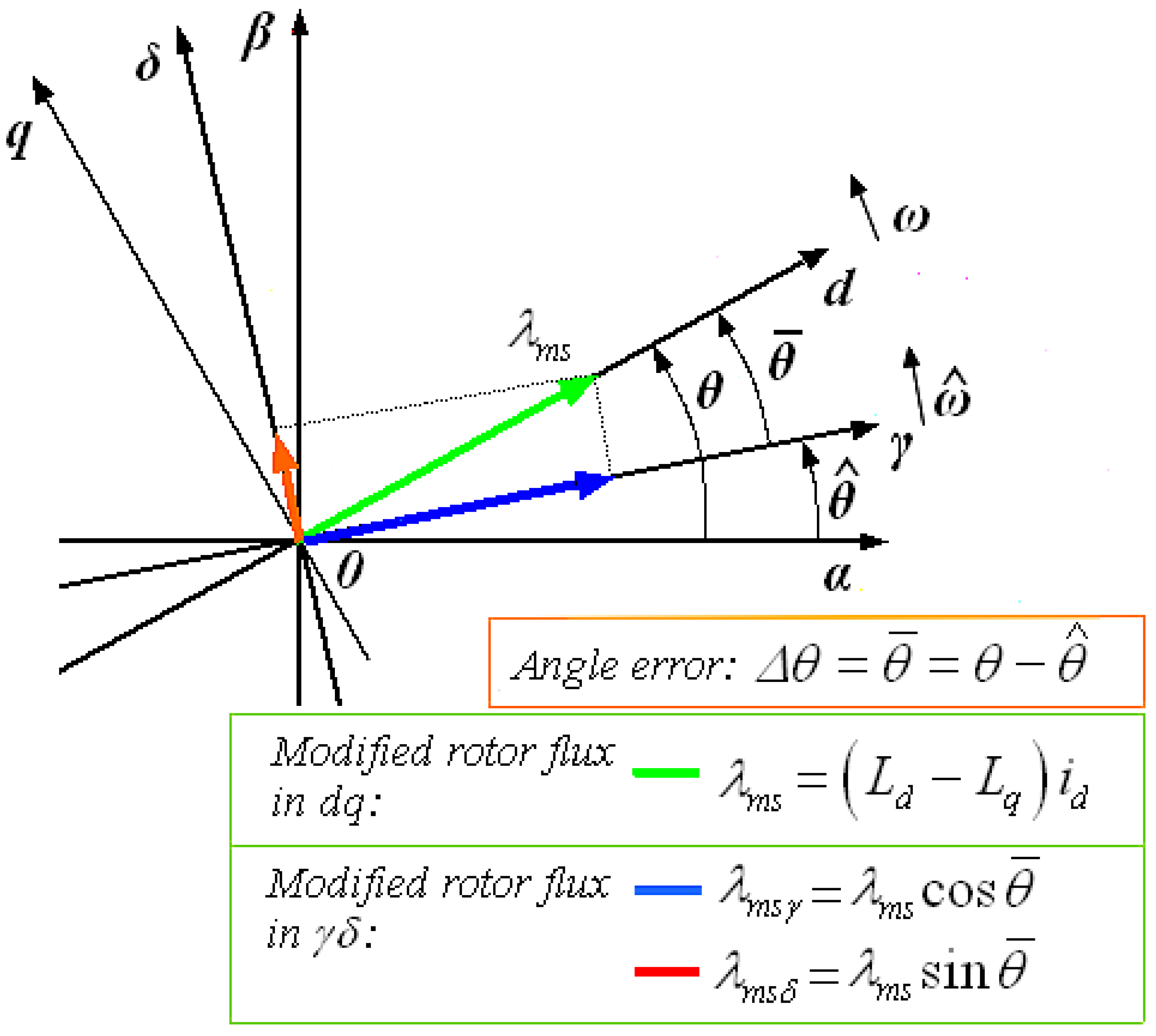
Unlike PMSM, there is no rotor flux in SynRM. In Equation (6), the modified rotor flux of SynRM is defined as λms, which is directly contingent on the d-axis stator current, id, and the inductance difference (LdLq). Comparing the modified rotor flux of the SynRM model in (6) with the modified rotor flux of the PMSM model proposed in [42], it is worth noting the absence of the permanent magnet flux λm in SynRM. Nevertheless, the analysis of the SynRM model is similar enough to that of the salient-pole PMSM model [42]. The directions of the flux vector λms and d-axis are identical (see Figure 3). Also, the magnetic flux λms is clearly in direct proportion to the id current for a given saliency, i.e., (LdLq) = const. Practically, when the id current is very small, the resultant flux λms is close to zero.

2.2. Modified SynRM Voltage and the Flux/Current Model in the Estimated Reference Frame γδ

In sensorless control, the estimated reference frame is defined as an arbitrary reference frame that rotates at an estimated angular speed while lagging behind the dq synchronous frame by the angle Δθ, i.e., the angle difference between the dq and γδ rotating reference frames (see Figure 3). Although the idea of the arbitrary rotating reference frame γδ might seem hypothetical, its application in sensorless control is advantageous for analyzing electrical machines with simplicity and enabling the development of advanced sensorless strategies. Conventionally, the SynRM model in γδ is derived by applying the appropriate variable transformation to the analogous SynRM model in dq. By definition, the applied variable transformation is based on the matrix KΔθ determined as follows:
K Δ θ = cos θ ¯ sin θ ¯ sin θ ¯ cos θ ¯ .
Equation (7) yields that the KΔθ transformation matrix is only dependent on the difference in angle between the dq and γδ reference frames [42]. After multiplying both parts of Equations (1) and (2) from the left by the matrix KΔθ, the resulting equations for the stator voltage and flux of the corresponding SynRM model in γδ are formulated as follows:
K Δ θ u d q = K Δ θ r s i d q + K Δ θ ω J s λ d q + K Δ θ λ ˙ d q u γ δ = r s i γ δ + ω J s λ γ δ + θ ¯ ˙ J s λ γ δ + λ ˙ γ δ u γ δ = r s i γ δ + ω ^ J s λ γ δ + λ ˙ γ δ ,
and
λ γ δ = L q q K Δ θ i d q + K Δ θ λ m s d q = L q q i γ δ + λ m s γ δ .
Here, the term λmsγδ represents the modified rotor flux λsm expressed in the γδ reference frame, while its components, λmsγ and λmsδ, are analytically given by
λ m s γ δ = K Δ θ λ m s d q = cos θ ¯ sin θ ¯ sin θ ¯ cos θ ¯ λ m s 1 0 = λ m s cos θ ¯ λ m s sin θ ¯ = λ m s γ λ m s δ .
In Equation (10), the flux components, λmsγ and λmsδ, are functions of the modified rotor flux λms and the angle deviation between the dq and γδ rotating reference frames. The application of state observers enables the estimations of both λmsγ and λmsδ, which can be utilized to derive the speed and position of the SynRM rotor.

2.3. Analysis of Modified Rotor Flux in γδ Reference Frame

Solving Equation (8) for the first time derivative of the stator flux, γδ/dt, results in
7 λ ˙ γ δ = u γ δ r s i γ δ ω ^ J s λ γ δ .
After taking the first-time derivative of both parts in (9) and substituting it into (11), it will be
λ ˙ γ δ = L q q i ˙ γ δ + λ ˙ m s γ δ = u γ δ r s i γ δ ω ^ J s λ γ δ L q q i ˙ γ δ = u γ δ r s i γ δ ω ^ J s λ γ δ λ ˙ m s γ δ .
Also, taking the first-time derivative of λmsγδ in (10) and setting the first-time derivative of angle error equal to the speed error, i.e., θ ¯ ˙ = ω ¯ , it results in
10 d / d t λ ˙ m s γ δ = λ ˙ m s γ λ ˙ m s δ = d d t λ m s cos θ ¯ λ m s sin θ ¯ = d d t L d L q i d cos θ ¯ L d L q i d sin θ ¯ = L d L q i ˙ d cos θ ¯ θ ¯ ˙ i d sin θ ¯ i ˙ d sin θ ¯ + θ ¯ ˙ i d cos θ ¯ θ ¯ ˙ = ω ¯ λ ˙ m s γ δ = L d L q i ˙ d cos θ ¯ ω ¯ i d sin θ ¯ i ˙ d sin θ ¯ + ω ¯ i d cos θ ¯ .
Assuming that the id current controller converges very quickly, i.e., did/dt ≅ 0, Equation (13) is rewritten in a more simple form:
λ ˙ m s γ δ = λ ˙ m s γ λ ˙ m s δ L d L q ω ¯ i d sin θ ¯ L d L q ω ¯ i d cos θ ¯ = ω ¯ L d L q i d sin θ ¯ L d L q i d cos θ ¯ = ω ¯ J s λ m s γ δ .
Equations (9)–(11) could be used to schematically show the modified γδ model of SynRM in the form of block diagrams (see Figure 4).

3. Flux/Current Observer Based on Sliding Mode and Equivalent Control Methodologies

3.1. Design of Flux/Current Observer

Conventionally, the design of SMO is composed of two main phases: (a) the choice of suitable hyperplane or sliding manifold to satisfy certain specifications; and (b) the selection of proper switching control inputs (i.e., control law) such that the system states converge towards the sliding manifold in finite time. Specific design parameters for the selected hyperplane and switching control functions should be included to ensure that the observer satisfies the required stability criteria and high performance. Particularly, the SMO stability is examined through the existence conditions of sliding mode. However, if the complexity of the sliding surface design increases, more effort is needed to cope with challenges in designing the SMO control laws and satisfying the stability conditions. In addition, the control gains of the switching functions are very significant in achieving the observer stability criteria. Even though the SMO operates in sliding mode, the system’s trajectories are still affected by the applied discontinuous control, which remains active. In the subsequent paragraphs, the equivalent control methodology is applied to a first-order SMO. Regarding the observer convergence, this is attained using properly chosen control inputs, which are functions based on the stator current errors.
In designing the SMO, the chosen sliding manifold, i.e., the sliding surfaces, and switching control inputs are determined in the following manner:
s γ δ = i ¯ γ δ = s γ s δ = i ¯ γ i ¯ δ v γ δ = k γ δ sgn i ¯ γ δ = k γ sgn s γ k δ sgn s δ = k γ sgn i ¯ γ k δ sgn i ¯ δ ,
Here, the matrices sγδ and vγδ represent the sliding surfaces and the control inputs of SMO, respectively, using the errors of the stator current in γδ. Additionally, the definition of the flux/current SMO is presented by
L q q i ^ ˙ γ δ = u γ δ r ^ s i γ δ ω ^ J s λ γ δ + v γ δ .

3.2. Observer Dynamics and Stability in the Sense of Lyapunov

Subtracting by parts Equation (16) from Equation (12), the observer dynamics are derived as follows:
L q q i ¯ ˙ γ δ = r ¯ s i γ δ λ ˙ m s γ δ k γ δ sgn i ¯ γ δ .
In examining the stability conditions of SMO, a Lyapunov Candidate Function (LCF) Vir is properly chosen, such as
V i r = 1 2 L q i ¯ γ 2 + i ¯ δ 2 + 1 γ r r ¯ s 2 0 .
In (18), the function Vir is positive definite in the domain R3 with variables presented by stator current errors and resistance error. Also, at the origin (point 0 ≡ (0,0,0)), it is obviously Vir(0,0,0) = 0. Additionally, if the first-time derivative of Vir is negative definite, i.e., dVir/dt ≤ 0, the observer stability is guaranteed. After differentiating both parts of (18), it will be
V ˙ i r = L q i ¯ γ i ¯ ˙ γ + i ¯ δ i ¯ ˙ δ + 1 γ r r ¯ s r ¯ ˙ s 0 V ˙ i r = i ¯ γ r ¯ s i γ λ ˙ m s γ k γ sgn i ¯ γ γ + i ¯ δ r ¯ s i δ λ ˙ m s δ k δ sgn i ¯ δ + 1 γ r r ¯ s r ¯ ˙ s 0 V ˙ i r = r ¯ s i γ i ¯ γ λ ˙ m s γ i ¯ γ k γ i ¯ γ + r ¯ s i δ i ¯ δ λ ˙ m s δ i ¯ δ k δ i ¯ δ + 1 γ r r ¯ s r ¯ ˙ s 0 V ˙ i r = λ ˙ m s γ i ¯ γ k γ i ¯ γ + λ ˙ m s δ i ¯ δ k δ i ¯ δ + 1 γ r r ¯ s r ¯ ˙ s γ r i γ i ¯ γ + i δ i ¯ δ 0 .
It can be seen that Relation (19) is satisfied if the following relations are valid:
k γ i ¯ γ λ ˙ m s γ i ¯ γ < 0   i f   k γ > λ ˙ m s γ λ ˙ m s γ ,
k δ i ¯ δ λ ˙ m s δ i ¯ δ < 0   i f   k δ > λ ˙ m s δ λ ˙ m s δ ,
1 γ r r ¯ s r ¯ ˙ s γ r i γ i ¯ γ + i δ i ¯ δ = 0 .
The inequalities in (20) and (21) express the so-called Sliding Mode Existence Conditions. These conditions are necessary for attaining the sliding mode after a finite time tr. Here, tr represents the duration of the reaching phase. Assuming that the resistance of stator, rs, varies slowly compared with the SMO dynamics, Equation (22) could be used to estimate the stator resistance rs, i.e.,
  r ¯ ˙ s = r ˙ s r ^ ˙ s r ˙ s 0 r ¯ ˙ s = r ^ ˙ s 1 γ r r ¯ s r ¯ ˙ s γ r i γ i ¯ γ + i δ i ¯ δ = 0 r ^ ˙ s γ r i γ i ¯ γ + i δ i ¯ δ = 0 r ^ ˙ s = γ r i γ i ¯ γ + i δ i ¯ δ ,
The stator resistance estimator is defined by Equation (23), where γr represents the estimator gain with γr > 0. Based on Equation (23), an observer can be properly designed for the accurate estimation of the stator resistance, rs, during SynRM operation. Mainly, changes in stator resistance, rs, are due to the temperature increment of stator windings, e.g., in the case of inadequate cooling.

3.3. Sliding Mode Observer and Equivalent Control Inputs

Initially, the current/flux SMO is forced towards the sliding manifold due to the control inputs vγδ. After a finite time tr (reaching time), the flux/current SMO operates in sliding mode, becoming stable. This means that the estimated variables of SMO (e.g., stator currents) converge to the real ones, implying that the observer system states in (17) are on the sliding surfaces sγ and sδ, as defined in (15). Considering Equation (23), it is assumed that the stator resistance changes slowly compared to the observer dynamics, i.e., the stator resistance observer converges quickly, resulting in a very small stator resistance error. Therefore, the stator resistance error could be omitted for simplicity reasons. Furthermore, once the SMO is operating in sliding mode, it is dsγ/dt = 0, dsδ/dt = 0, and the control inputs, vγ and vδ, are, respectively, becoming equal to the so-called Equivalent Control Inputs, vγeq and vδeq [48,49]. Hence, Equation (17) can be further simplified as follows:
L q q i ¯ ˙ γ δ = r ¯ s i γ δ λ ˙ m s γ δ k γ δ sgn i ¯ γ δ s ˙ γ δ = i ¯ ˙ γ δ = 0 r ¯ s 0 0 = λ ˙ m s γ δ k γ δ sgn i ¯ γ δ e q λ ˙ m s γ δ = k γ δ sgn i ¯ γ δ e q λ ˙ m s γ λ ˙ m s δ = k γ sgn i ¯ γ e q k δ sgn i ¯ δ e q .
Substituting the terms of msγδ/dt obtained from (14) into the left-hand side of (24), the following relation is derived:
L d L q ω ¯ i d sin θ ¯ L d L q ω ¯ i d cos θ ¯ = k γ sgn i ¯ γ e q k δ sgn i ¯ δ e q .
According to Equation (25), the equivalent control inputs include speed error and angle error information in the form of trigonometric functions. Therefore, the equivalent control inputs could be used to estimate both the angular speed and position of SynRM through the application of a modified EMF observer.

4. Modified EMF Observer for Estimating the Speed and Position of SynRM

4.1. Design of Modified EMF Observer for Speed and Position

On the basis of the previous analysis, the modified EMF is introduced to design a modified EMF observer that has the ability to precisely estimate the SynRM angular speed and position. Let the modified EMF of SynRM Esγδ be defined as follows:
E γ δ = E γ E δ = ω L d L q i d sin θ ¯ ω L d L q i d cos θ ¯ = ω 0 1 1 0 L d L q i d cos θ ¯ L d L q i d sin θ ¯ = ω J s λ m s γ δ .
Assuming that the id current controller converges very quickly, as did/dt ≅ 0, and that the real speed ω changes very slowly like dω/dt ≅ 0 and setting θ ¯ ˙ = ω ¯ , the first-time derivative of Esγδ could be approximated as follows:
26 d E γ δ d t = E ˙ γ δ = E ˙ γ E ˙ δ θ ¯ ˙ ω L d L q i d cos θ ¯ θ ¯ ˙ ω L d L q i d sin θ ¯ = ω ¯ E δ ω ¯ E γ .
Here, the assumption dω/dt ≅ 0 implies that the observer’s dynamics for estimating the speed and position is significantly faster than the variation in the rotor speed. In the observer design, the equivalent inputs in (25) are used as modified EMF errors, since they embed speed and position errors, i.e.,
E ¯ γ E ¯ δ = L d L q ω ¯ i d sin θ ¯ L d L q ω ¯ i d cos θ ¯ = k γ sgn i ¯ γ e q k δ sgn i ¯ δ e q .
Regarding the estimated modified EMF, the definition of the observer’s dynamics is determined simply by
E ^ ˙ δ γ = E ^ ˙ γ E ^ ˙ δ = 0 γ E E ¯ δ
Here, γE represents the gain of the modified EMF observer with γE > 0. Particularly, this gain is related to the estimation of the δ-axis EMF component. Also, by subtracting Equation (29) from Equation (27), the error dynamics of the modified EMF observer can be written in the following form:
27 29 E ¯ ˙ δ γ = E ¯ ˙ γ E ¯ ˙ δ = E ˙ γ E ^ ˙ γ E ˙ δ E ^ ˙ δ = ω ¯ E δ 0 ω ¯ E γ + γ E E ¯ δ .

4.2. Stability of the Modified EMF Observer

The following function VEω is chosen as a suitable LCF for the modified EMF observer defined by
V E ω = 1 2 E ¯ γ 2 + E ¯ δ 2 + 1 γ ω ω ¯ 2 0 .
In Equation (31), the term γω represents the gain of speed observer with γω > 0. Since the function V is positive definite, the observer is stable in accordance with the Lyapunov’s stability criteria if the first-time derivative of V is negative definite, i.e., dV/dt ≤ 0. Therefore, it will be
V ˙ E ω = E ¯ ˙ γ E ¯ γ + E ¯ ˙ δ E ¯ δ + 1 γ ω ω ¯ ˙ ω ¯ 0 V ˙ E ω = ω ¯ E ¯ γ E ^ δ γ E E ¯ δ 2 + 1 γ ω ω ¯ ˙ ω ¯ 0 V ˙ E ω = γ E E ¯ δ 2 + 1 γ ω ω ¯ ω ¯ ˙ γ ω E ¯ γ E ^ δ 0 .
Relation (32) is satisfied if the following conditions are valid:
γ E E ¯ δ 2 0 ,
and
ω ¯ ˙ γ ω E ¯ γ E ^ δ = 0 .
The conditions expressed in both Equations (33) and (34) are sufficient for the asymptotic stability of the modified EMF observer in the sense of Lyapunov. Specifically, the condition in Equation (33) is valid for γE > 0, while Equation (34) determines the speed observer dynamics.

4.3. Speed and Position Estimation

Assuming again that the dynamics of the modified EMF observer is much faster than the actual rotor speed changes, the first-time derivative of the rotor speed is close to zero, i.e., dω/dt ≅ 0 (see Equation (27)). Considering Equation (34), the speed could be approximated as shown in Equation (35):
ω ˙ 0 ω ¯ ˙ γ ω E ¯ γ E ^ δ = 0 ω ^ ˙ γ ω E ¯ γ E ^ δ = 0 ω ^ ˙ = γ ω E ¯ γ E ^ δ .
Equation (35) defines the angular speed observer, while the estimated angular position is obtained directly from (35) via integrating by parts, i.e.,
( 35 ) ω ^ ˙ = γ ω E ¯ γ E ^ δ θ ^ ˙ = 0 t ω ^ ˙ d t = 0 t γ ω E ¯ γ E ^ δ d t
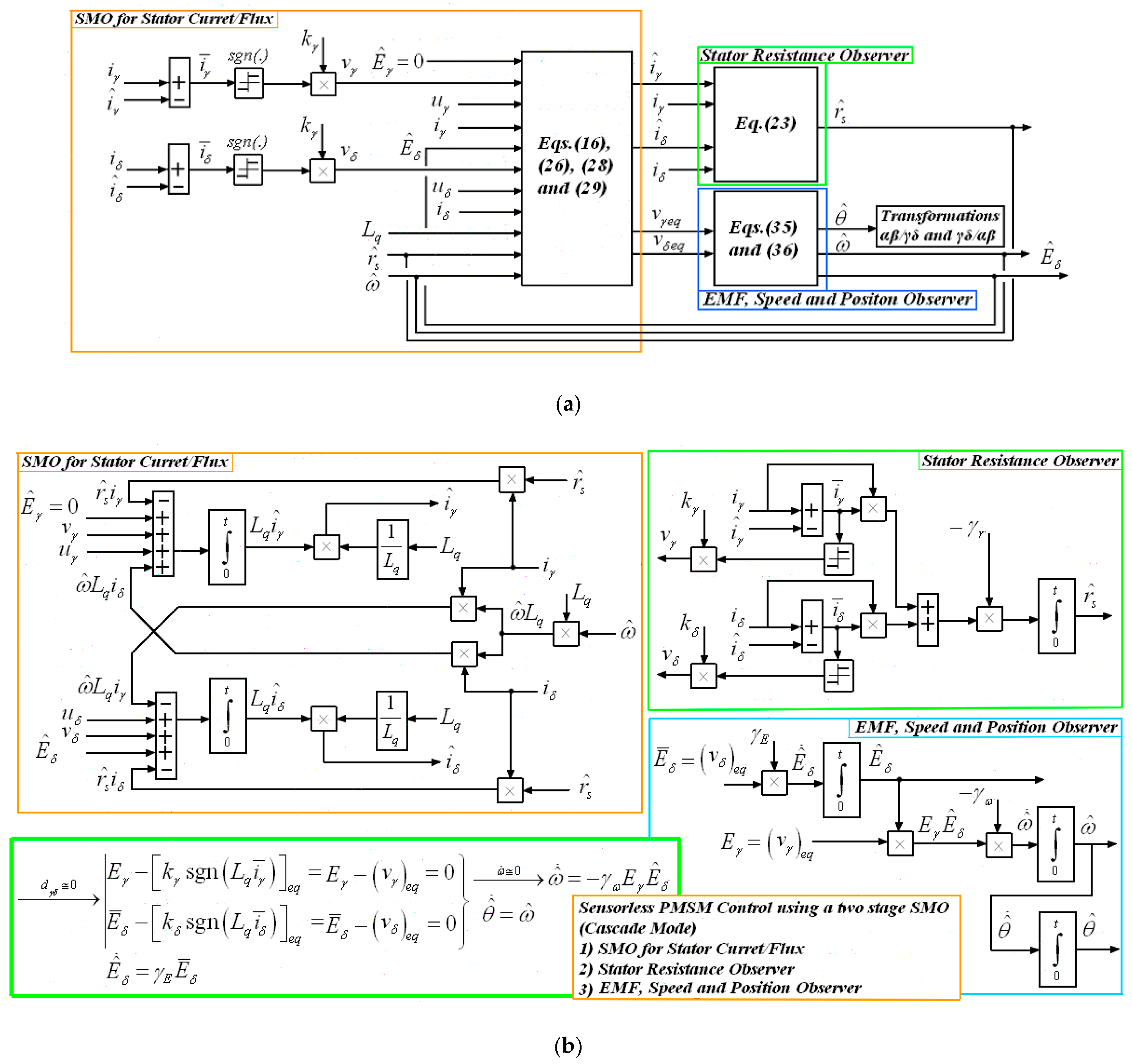
The gains γE and γω significantly affect the stability and estimation accuracy of the modified EMF observer. Figure 5a illustrates the entire observer scheme and the interconnection between the SMO and modified EMF observer in the form of a block diagram. Moreover, the partial observers are depicted in Figure 5b.

5. Simulation Results

5.1. Description of the Controller–Observer System, Simulated SynRM Model, and Voltage Source Inverter (VSI)

The design of the proposed sensorless approach is implemented using the developed modified SynRM model that is expressed in the γδ reference system. Figure 1 illustrates the structure of the overall vector control of SynRM applying the previously mentioned sensorless algorithm. For test and evaluation purposes, the Simulink/Matlab application is used to study the controller–observer system for SynRM including the SynRM behavior in transient states. The simulation of SynRM relies on Equations (5)–(14) that are formulated in the γδ reference frame, whereas the related flux/current and modified EMF observers employ Equations (15)–(36). Specifically, Equations (15)–(22) are used to estimate stator flux/currents, while the estimation of modified EMF, rotor speed, and position is carried out through Equations (26)–(36) using equivalent control inputs derived from Equation (25). In addition, the parameters of the simulated and tested SynRM model are listed in Table 1. It is worthy to note that the SynRM saliency is positive, i.e., Ld > Lq or ΔL = (Ld − Lq) > 0. Therefore, the produced torque Te is positive in the case of positive id and iq currents. Also, a 3-phase VSI is used to feed the SynRM connected to a dc voltage of 540 V. In simulations, the Space Vector PWM technique is utilized to attain the desired voltage in the output of VSI. Also, the switching frequency is set at 5 kHz (i.e., Tz = 0.2 ms). The whole observer and all its connections are depicted in Figure 5a with the numbers of equations for each segment. In addition, Figure 5b shows the modified EMF observer with more details, as it is described in Equations (29), (35), and (36). Regarding the stability of the flux/current and modified EMF observers, their selected gains are listed in Table 2 and Table 3, respectively. The set of gain values is selected on the basis of Relations (21), (22), (24), (33), and (35).

5.2. SMO and EMF Observer Response at Low Speed and Standstill

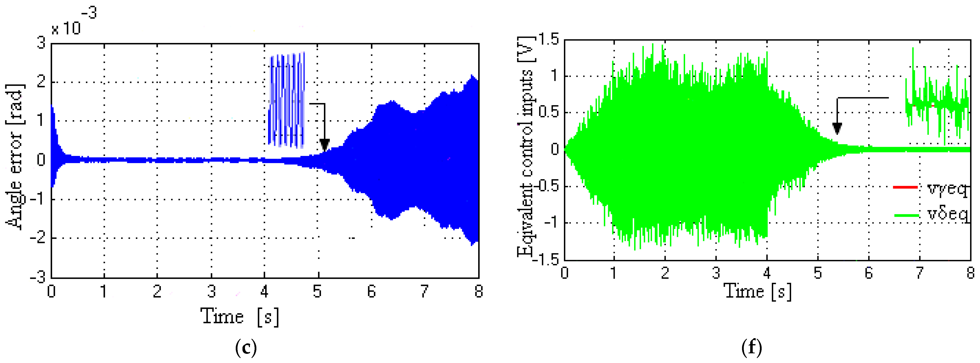
Figure 6 and Figure 7 present simulation results, while the reference speed is changed and an external torque disturbance is affecting the SynRM. In particular, two stepwise changes are applied in the reference speed, from 0 rad/s to 20π rad/s (or 10 Hz) at t0 = 0 s, and from 20π rad/s to 0 rad/s (standstill operation) at time t3 = 4 s. Also, an external torque (or load torque) TL of 2 Nm is applied to the rotor at time t1 = 2 s, and then it is uncoupled at time t2 = 3 s. In both Figure 6 and Figure 7, the simulations are carried out with the γ-axis reference current set at 1 A, i.e., iγ* = 1 A.
Figure 6a–c show both the rotor speed and angle (real and estimated) as well as the angle error. In addition, the modified rotor flux (real) in γδ, the modified EMF Eδ (estimated), and the equivalent control inputs in γδ are shown in Figure 6d, Figure 6e, and Figure 6f, respectively. Figure 6a–c demonstrate that the observer system consisting of an SMO and an EMF observer converges very quickly. Also, the SMO remains in sliding mode despite the applied external torque and speed changes that allow for accurate speed and position estimation. Furthermore, the modified EMF observer supplies precise information regarding the estimated Eδ component of EMF in the γδ reference system, which enables an almost precise estimation of both rotor speed and angle. It is worth mentioning that the modified EMF observer error remains fairly small to maintain its excellent performance even during standstill operation.
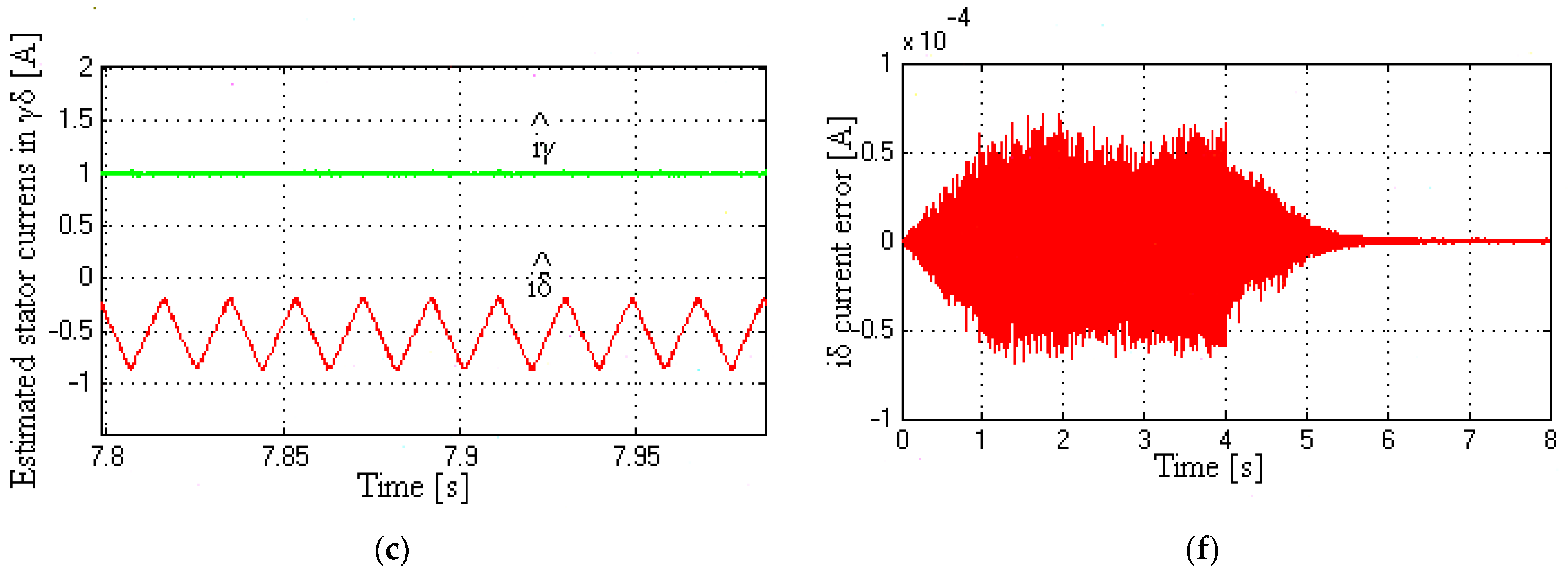
The responses of the estimated stator currents in the γδ system are shown in Figure 7a, while Figure 7b illustrates the real stator currents in the abc static reference frame. Also, Figure 7c shows the SMO response in estimating the currents iγ and iδ at a time interval from 7.8 s to 8.0 s, where the real and estimated rotor speeds are almost zero. Particularly, the chattering phenomenon of the iδ current is mostly obvious in the lower part of Figure 7c. This chattering occurs as a result of the applied switching control vδ that changes at very high frequencies. In addition, Figure 7d presents the response of the produced electrical torque (reluctance torque) during stepwise changes in speed reference and torque load. Finally, Figure 7e, f show that both stator current errors in γδ are preserved very small, even though the speed and torque change. The influence of variation in load torque is evident in the estimated current iδ and its error at the time interval from 2 s to 3 s, as depicted in Figure 7a, f.

5.3. Modified Rotor Flux and EMF Observer Response at Medium Speed

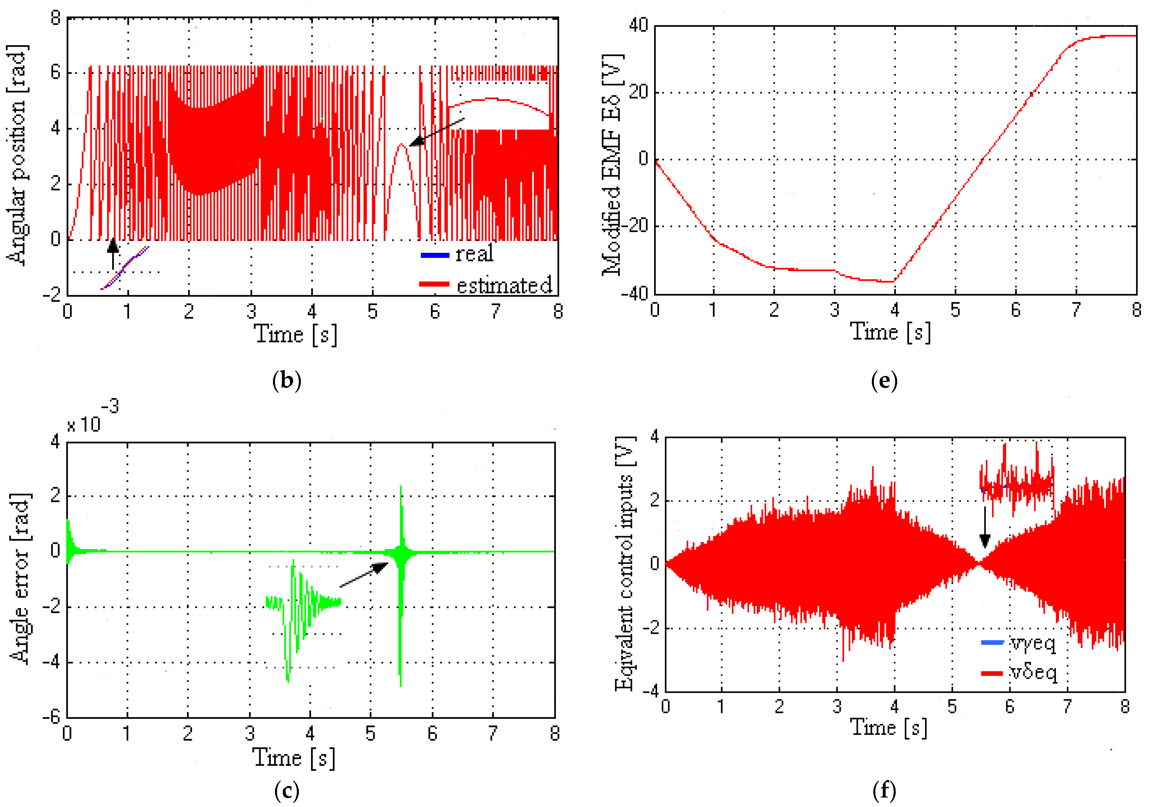
Figure 8 shows the behavior of the modified EMF observer at medium speed while an external torque disturbance and reference speed changes are present. In particular, the speed changes stepwise from 0 rad/s to 40π rad/s (or 20 Hz) at t0 = 0 s and from 40π rad/s to −40π rad/s at t3 = 4 s. Additionally, an external torque disturbance TL of 4 Nm is initially applied to the SynRM rotor at t1 = 1 s, which is subsequently removed after 2 s, i.e., at t2 = 3 s. In Figure 8, the simulations are carried out by initially setting the γ-axis reference current equal to 1.5 A, i.e., iγ* = 1.5 A. The rotor angle (real and estimated), rotor speed (real and estimated), and angle error are illustrated in Figure 8a, Figure 8b, and Figure 8c, respectively. Moreover, Figure 8d demonstrates both the λmsγ and λmsδ components of the modified rotor flux, while Figure 8e displays the modified EMF Eδ. Also, equivalent control inputs are shown in Figure 8f. Inspecting Figure 8, it is observed that the estimated values of speed, angle, and modified EMF are remarkably close to the actual values, pointing out the high level of estimation precision of both the SMO and modified EMF observer. However, the equivalent control input, vδeq, is influenced by the torque disturbances and speed changes (see Figure 8f).

5.4. Speed, Angle, Modified Rotor Flux, Modified EMF, and Control Inputs at Very Low to Medium Speeds

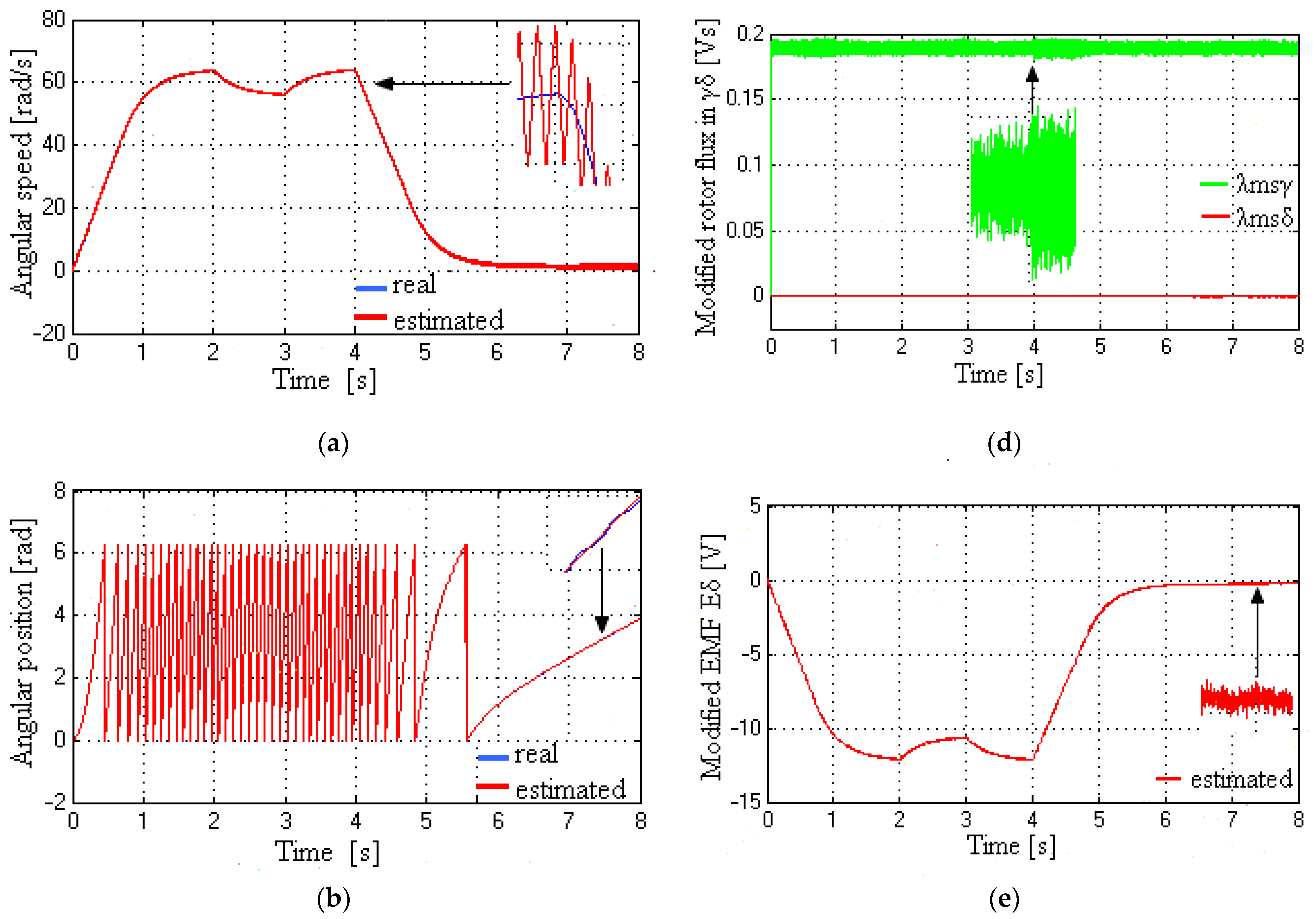
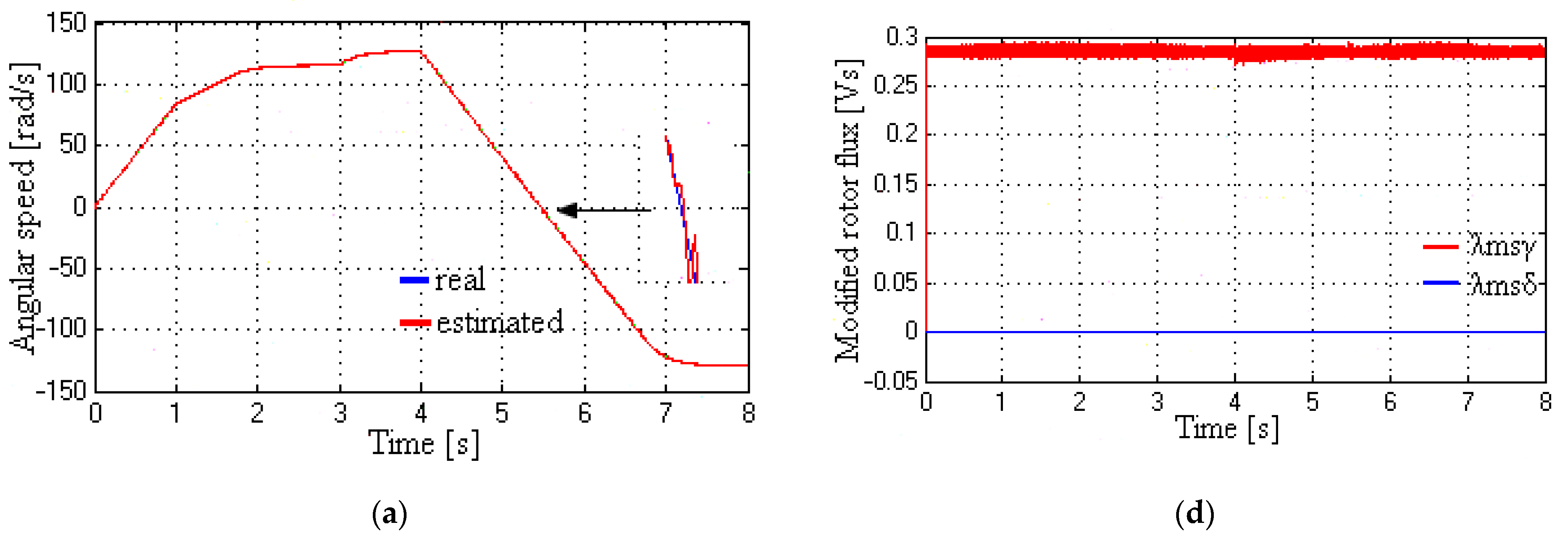
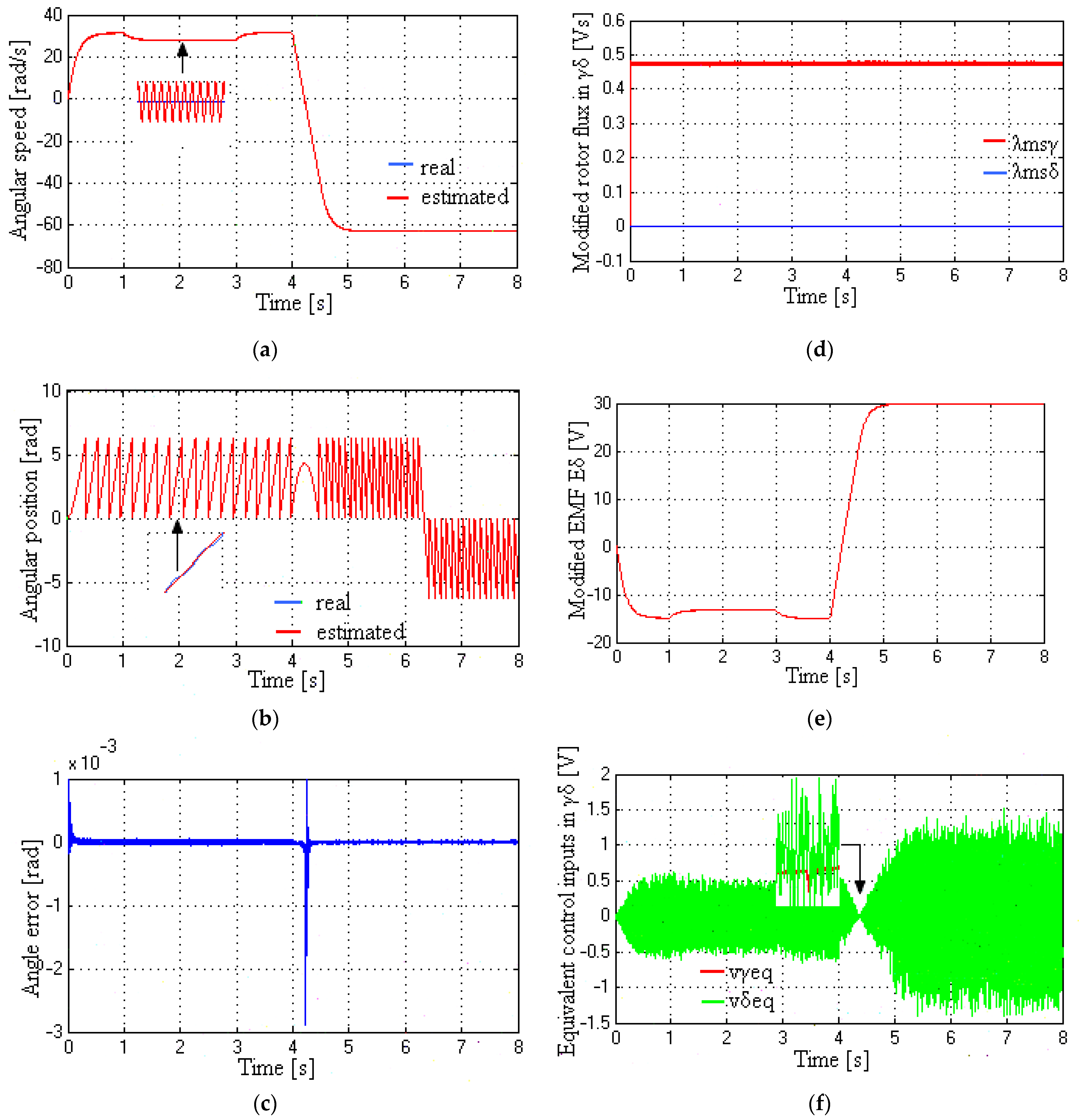
In Figure 9, the reference speed is changed stepwise at the beginning, from 0π rad/s to 10π rad/s (or 5 Hz) at time t0 = 0 s and then from 10π rad/s to −20π rad/s (or −10 Hz) at t4 = 4 s, while a load torque TL of 2 Nm is applied as an external torque disturbance. The load toque TL is applied at time t1 = 1 s, and thereafter it is removed at time t2 = 3 s. Also, the γ-axis reference current is set to 2.5 A. The speed and angle responses (both real and estimated) are presented in Figure 9a and Figure 9b, respectively. Moreover, the angle error is illustrated in Figure 9c, where there is an apparent sudden change in angle error after reversing the speed at time t4 = 4 s. The modified rotor flux and the estimated Eδ component of the modified EMF are shown in Figure 9d and Figure 9e, respectively. In addition, the equivalent control inputs, vγeq and vδeq, are shown in Figure 9f.
It should be mentioned that the torque load TL evidently affects the rotor speed and the estimated EMF Eδ during the time interval from t1 = 1 s to t3 = 3 s. Nevertheless, it can be seen that the estimated SynRM variables, such as speed, angle, and modified EMF Eδ, are still very close to the corresponding real ones. This implies that the proposed estimation scheme behaves well with high accuracy. Nonetheless, the accuracy might strongly be affected by the angle information extracted from both equivalent control inputs, vγeq and vδeq. As the estimated angle approximates the real one, the angle error tends to zero, resulting in the coincidence of the γδ reference frame with the dq synchronous reference system (see Figure 3). Also, considering the convergence of the entire observer scheme, the estimated variables of SynRM (e.g., stator currents, modified EMF, etc.) are becoming almost equal to the corresponding real variables. Inspecting Figure 6a,c on the left part, it can be observed that the increased chattering on the angle error leads to an increment of the chattering in the estimated speed as well. The estimation accuracy is maintained at a high level, as the SMO is kept in sliding mode with acceptable chattering and the modified EMF observer converges very quickly.

5.5. Responses of Stator Currents (Real and Estimated) and Torque Response at Very Low to Medium Speeds

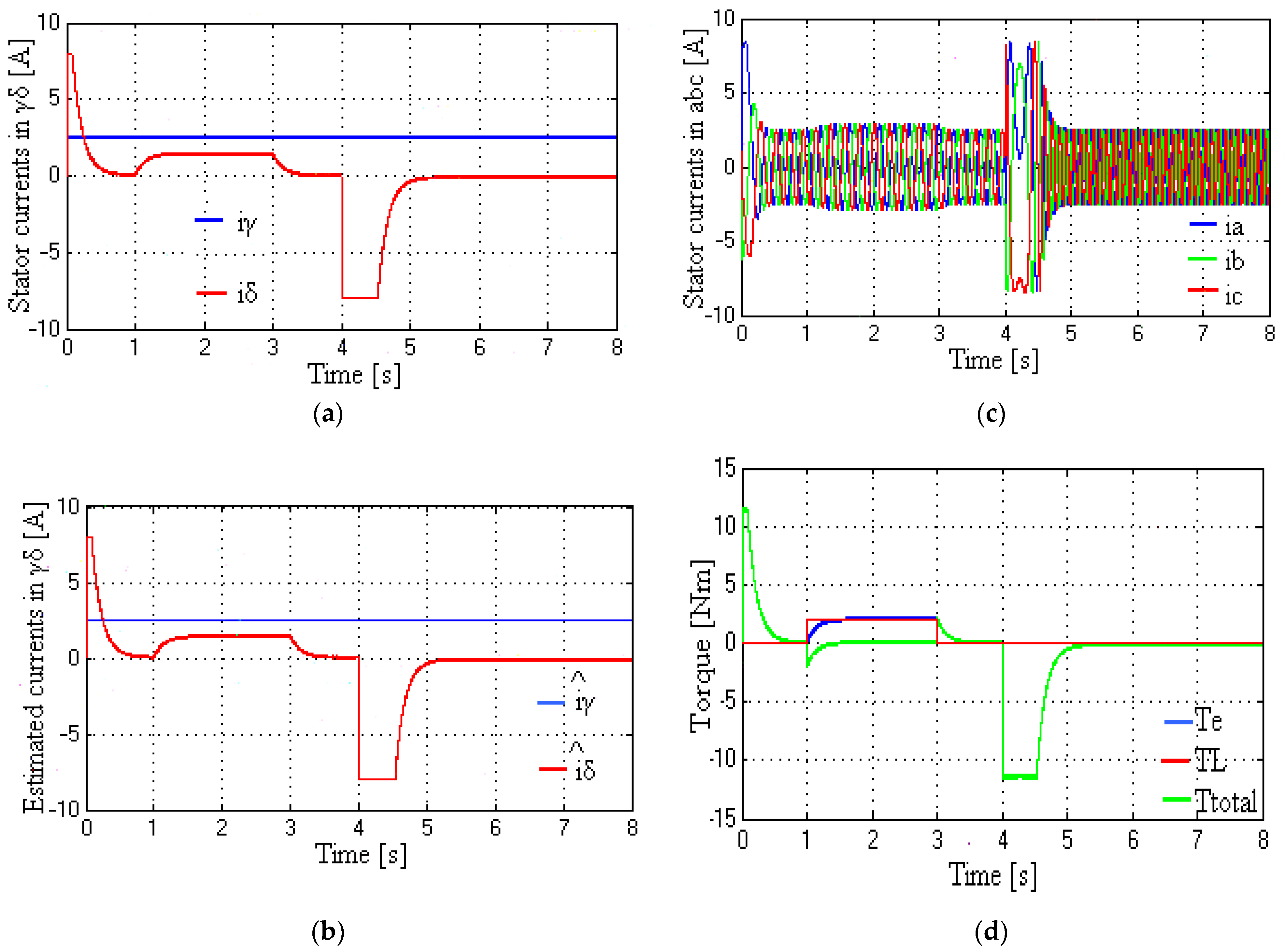
The stator currents and torque responses are shown in Figure 10. Here, the reference speed and load torque change in the same way as in Figure 9, i.e., the reference speed is changed stepwise from 0 rad/s to 10π rad/s at t0 = 0 s and from 10π rad/s to −20π rad/s at t3 = 4 s, while an external torque TL of 2 Nm is applied at t1 = 1 s and subsequently removed at t2 = 3 s. The real and the estimated stator currents in the γδ reference frame are demonstrated in Figure 10a and Figure 10b, respectively. Also, the real stator currents in the abc stationary frame are presented in Figure 10c. In addition, the produced torque Te, the load torque TL, and the total torque Ttot are illustrated in Figure 10d. After observing the responses in Figure 10, it is obvious that both the speed change and the load torque TL variation affect the stator currents and torque Te. However, the overall controller–observer system of SynRM remains stable, providing accurate estimations of stator currents despite the external disturbance applied.

6. Discussion

After comparing the real and estimated SynRM variables in Figure 6, Figure 7, Figure 8, Figure 9 and Figure 10, it is observed that the estimations of angular speed and position, stator currents, and modified EMF are obtained with high accuracy. Also, the observer behaves well, showing robustness and stability in the presence of speed reversal and torque load disturbances. Considering the accuracy, it could be mentioned that the angle is estimated with an average accuracy of ±10−4 rad and ±1.5 × 10⁻³ rad for an angular speed of 20π rad/s (or 62.83 rad/s) and 0 rad/s, respectively, under load torque application and speed change (see Figure 6c, Figure 8c and Figure 9c). Also, the corresponding speed is estimated with an average accuracy of ±0.75 rad/s and ±1.25 rad/s for angular speed of 20π rad/s (or 62.83 rad/s) and 0 rad/s, respectively, under the same dynamic conditions regarding load torque and speed (see Figure 6a, Figure 8a and Figure 9a). However, the angle error exhibits a significant increment close to the zero-speed point, i.e., 0 rad/s, during the speed reversal. Particularly, the angle is estimated close to 0 rad/s with an average accuracy of −4.8 × 10⁻³ rad and +2.4 × 10⁻³ rad for angular speed change from 40π rad/s (or 125.66 rad/s) to −40π rad/s (see Figure 8c). Similarly, the angle is estimated close to 0 rad/s with an average accuracy of −2.8 × 10⁻³ rad and +10−3 rad for angular speed change from 10π rad/s (or 31.42 rad/s) to −20π rad/s (or −62.83 rad/s) (see Figure 9c). In addition, the stator current iγ is estimated with an average accuracy ±3 × 10⁻⁸ A for iγ, while the accuracy of the estimated stator current iδ varies from ±0.2 × 10⁻⁵ A to ±0.5 × 10⁻⁴ A, depending on the load torque and speed change (see Figure 7e,f).
It is well known that the chattering phenomenon is the primary drawback of sliding mode-based methods in consequence of the fast-switching control inputs [45,46,47,48]. However, the introduced chattering is very restricted, allowing the observer to remain in sliding mode after a limited time. The total controller–observer system is characterized by a significantly small chattering effect despite the high frequency signals introduced in the iγ and iδ estimations due to vγ and vδ (see Figure 7a,c,e,f). Regarding the chattering effect on the stability of the overall observer scheme, it should be mentioned that the choice of control inputs is very significant for attaining optimal observer operation. In addition, the equivalent control inputs are optimally adjusted to ensure SMO stability, while they can be used to extract the modified EMF and the required information on speed and position. It is also worthy to note that, unlike conventional methods based on EMF observers, the proposed modified EMF observer is capable of estimating SynRM position and speed at quite low speeds, even at standstill (see Figure 6a–c,e).
Although the sliding mode observers have been shown to be very efficient in dealing with parameter uncertainties and disturbances of nonlinear systems, the chattering is still an undesirable phenomenon that could drastically diminish estimation precision [46,47,48,49,50]. Also, the ideal sliding mode requires, theoretically, an infinite switching frequency. Nevertheless, the digital controllers execute the control-estimation algorithms based on a finite sampling rate, resulting in the discretization chatter. In the literature, numerous techniques have been proposed to address the issues of the chattering phenomenon, aiming to reduce or even eliminate its effect. The boundary layer design is a prevalent technique that employs a smooth continuous function in approximating the discontinuous sign function. This continuous approximation is defined within a bounded area (i.e., boundary layer) close to the sliding surface for providing a continuous control input and mitigating the chattering phenomenon [51,52,53]. However, the boundary layer design has disadvantages associated with the invariance property and the finite reaching time of sliding mode. As a consequence of the continuous approximation applied, the performance of SMO is affected by the thickness of the boundary layer and the finite reaching time towards the sliding surfaces may not be attained. Alternatively, Higher Order Sliding Mode Observers (HOSMOs) are proposed to address the chattering effect. The initial concept of sliding mode could be applied to higher-order time derivatives in HOSMO approaches while keeping the advantages of conventional SMO. Second-order SMO (SOSMO) has the simplest structure among the high-order sliding mode algorithms, but it may exhibit a chattering effect in the presence of unmodeled dynamics. As the HOSMO converges, the sliding mode occurs in a lower-order manifold after a finite time [54,55,56,57,58]. Additionally, the use of hyperbolic tangent function, tanh(.), and sigmoid functions could significantly improve the observer estimations, keeping the advantageous characteristics of the SMO [47,48,49,50]. Furthermore, the proper design of the sliding surfaces could enhance the SMO accuracy, decreasing the chattering phenomenon. Using auxiliary sliding surfaces allows the SMO to converge asymptotically when the auxiliary surface is reached [46]. However, the chattering reduction methods might increase the overall complexity of the estimation algorithm, requiring more computational power in real implementations of SMOs.
The presented method exhibits certain noteworthy characteristics in comparison to other proposed methods that are based on fundamental excitation strategies. It employs a relatively simple estimation algorithm whose design is based on an analytical mathematical model of the SynRM defined in the estimated reference frame γδ. Also, it is worth noting that modeling SynRM in γδ is advantageous for sensorless control, since the γδ reference system is an estimated system itself [18,21,22,42]. The so-called modified rotor flux is introduced to embed the saliency flux term (Ld − Lq)id, facilitating the SynRM flux analysis. Specifically, the modification of the magnetic flux is aimed at achieving a more convenient SynRM model that is suitable for speed and position estimation by embedding angle error terms. This allows the isolation of the terms containing angle error information. Furthermore, the analysis of the SynRM-modified model shows that the sensorless method could be applied to PMA SynRM as well, keeping almost the same model, except for the modifications related to the permanent magnets. The successful estimations for speed and position imply that the design of the SMO could be based on a unified model, regardless the specific AC machine type (PMSM salient or non-salient and SynRM). Although the developed observer is based on the fundamental excitation methodology, the modified EMF observer is capable of estimating speed and angle at medium, low, and very low speeds, even at standstill, with high accuracy [14,23,42]. Particularly, the proposed sensorless method exhibits acceptable chattering at a low-speed range while based on the equivalent control methodology of the first-order SMO. In addition, it is worth mentioning that only stator voltages and currents are used, while the modified EMF observer uses only the equivalent control inputs obtained from the SMO. The modified SynRM model could be applied as well to sensorless strategies based on saliency and signal injection.
In real-time applications, the proposed sensorless approach could be implemented through development boards based on microprocessors. Such a development board might normally use either a digital signal processor (DSP) or a multiprocessor unit (MPU) to support complex algorithms needing high computational power. Considering the simulation results in Figure 7a,e, it is observed that the id current controller converges very quickly. Also, the speed observer converges quickly even when the reference speed changes stepwise, as shown in Figure 6a, Figure 8a, and Figure 9a. However, the dynamic load torque and sudden speed changes have a significant impact on the sensorless control in real-time applications, due to the relation between the produced torque, friction torque, load torque, and speed acceleration. Particularly, a dynamic load torque may exhibit variations in direction, magnitude, and application time, resulting in varying speeds of the SynRM rotor. Therefore, it is essential to consider the dynamic load torque in order to design the control and estimation algorithms that can cope with the unpredictable load torques. For example, an extended observer could be designed to estimate load torque perturbations. This issue could be addressed using a powerful DSP-based card in real-time applications to execute the sampling of measured variables, estimation, and control algorithms. Using assumptions in sensorless control methods may result in less precise estimations than the corresponding measured or real values. Environmental factors, such as temperature, aging, humidity, noise, and load torque variation, may degrade the accuracy of the performed estimations [59,60]. Considering the performance of the proposed method, the SynRM parameters and variables, such as stator resistance and measured currents, may be affected by fluctuations in operating conditions, noise, and ambient temperature. However, the proposed algorithm could address these issues and overcome the problems associated with changes in environmental conditions based on the obtained results. The presented SMO and modified EMF observer can compensate for disturbances related to temperature variations and noise.
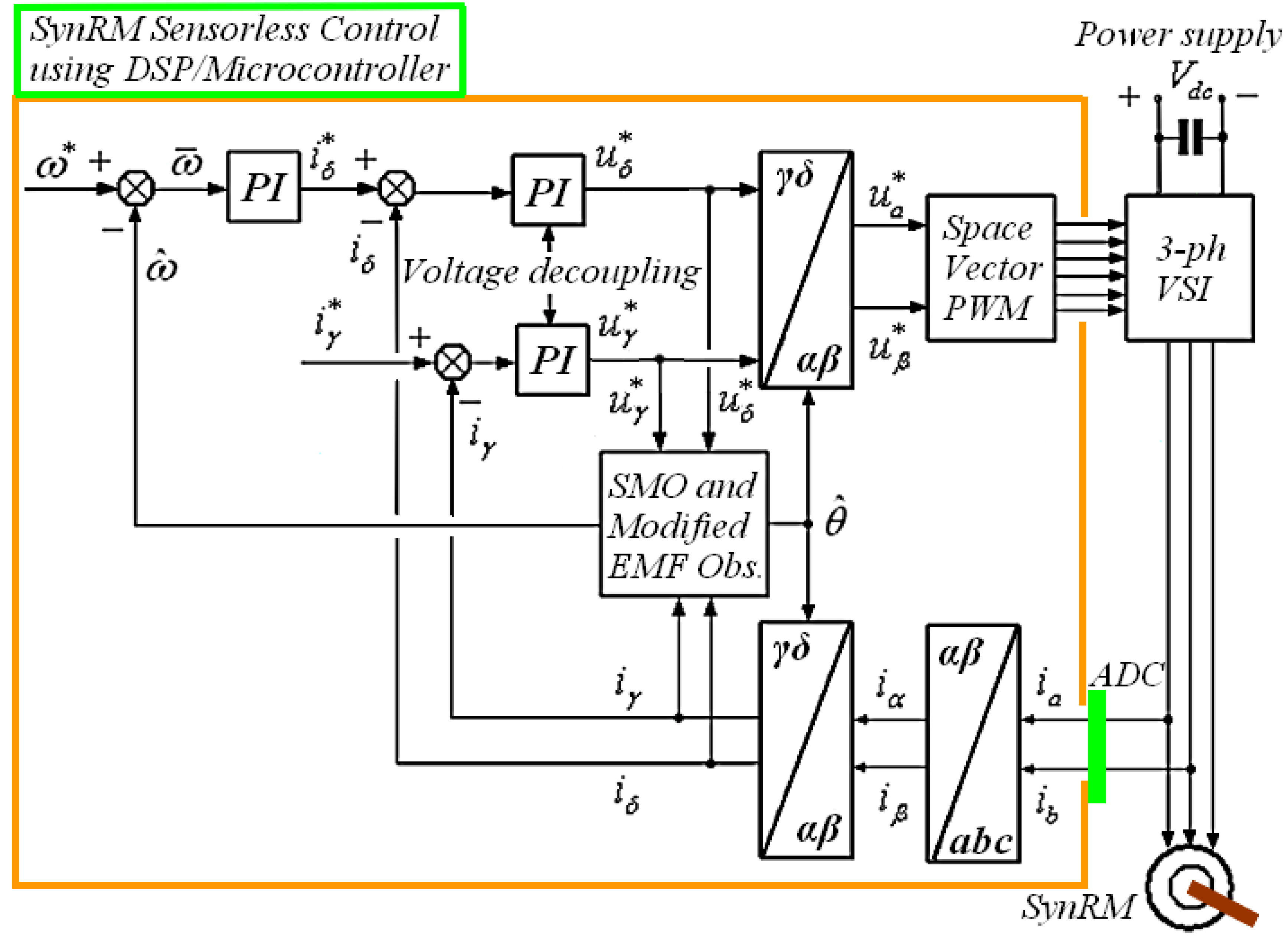
Conventionally, a DSP-based board could be used in future work to implement the external control loop (i.e., speed control loop), the internal control loops (i.e., current control loops for iγ and iδ), as well as the proposed estimation algorithm [61,62]. As an example, the DS1104 R&D Controller Board is a single-board solution of dSPACE that could be used in sensorless control applications of electrical machines [61]. Particularly, the provided Real-Time Interface (RTI) software (e.g., dSPACE Release: 2024-B) is utilized to directly implement the developed models in Simulink by running them on the real-time hardware. Figure 11 shows a typical diagram of the presented SynRM sensorless algorithm that is implemented using a DSP or microcontroller in real-time applications. All of the variables of SynRM (real, measured, and estimated) are expressed in the γδ reference system.

7. Conclusions

A novel sensorless method has been developed, tested, and evaluated for estimating, with high accuracy, the SynRM angular speed and position over a wide range of speeds employing a model-based observer. Both the SynRM mathematical model and the entire observer scheme are expressed in the γδ estimated reference frame. Established on the sliding modes methodology, the equivalent control inputs of the SMO are effectively utilized to achieve speed and position estimation via the modified EMF observer. It is shown that these accurate estimations could be successfully fed back to the controllers of currents and speed, keeping the overall observer–control system stable and robust. Furthermore, the overall sensorless algorithm is able to effectively compensate for external torque disturbances, and it is characterized by its very fast convergence and accurate estimates. Simulation results indicate the high performance of observer stability and verify the robustness and effectiveness of the presented estimation algorithm. The proposed observer scheme is assessed as an efficient sensorless approach that uses only the stator currents and voltages.

Funding

This research received no external funding.

Institutional Review Board Statement

Not applicable.

Informed Consent Statement

Not applicable.

Data Availability Statement

Data is contained within the article.

Conflicts of Interest

The author declares no conflicts of interest.

Notation

ud, uqdq axis stator voltages
id, iqdq axis stator currents
λd, λqdq axis stator magnetic fluxes
Ld, Lqdq axis inductances
λms = (LdLq)id modified rotor magnetic flux due to the saliency and id current
rsstator resistance
uγ, uδγδ axis stator voltages
iγ, iδγδ axis stator currents
λγ, λδγδ axis stator magnetic fluxes
λmsγδγδ axis of modified rotor magnetic flux
pnumber of pole pairs
θ = θeelectrical angular position
ω = ωeelectrical angular speed

References

  1. Lipo, T.A.; Miller, T.J.; Vagati, A.; Boldea, I.; Malesani, L.; Fukao, T. Synchronous Reluctance Drives. In Proceedings of the IEEE IAS Annual Meeting, Denver, CO, USA, 2–6 October 1994. [Google Scholar]
  2. Kamper, M.J.; Volschenk, A.F. Effect of rotor dimensions and cross magnetization on Ld and Lq inductances of reluctance synchronous machine with cage less flux barrier rotor. IEE Proc. Electric Power Appl. 1994, 141, 213–220. [Google Scholar] [CrossRef]
  3. Bianchi, N.; Bolognani, S.; Bon, D.; Dai Pré, M. Rotor Flux-Barrier Design for Torque Ripple Reduction in Synchronous Reluctance and PM-Assisted Synchronous Reluctance Motors. IEEE Trans. Ind. Appl. 2009, 45, 921–928. [Google Scholar] [CrossRef]
  4. Paradkar, M.; Boecker, J. Design of a High Performance Ferrite Magnet-Assisted Synchronous Reluctance Motor for an Electric Vehicle. In Proceedings of the IECON 2012-38th Annual Conference on IEEE Industrial Electronics Society, Montreal, QC, Canada, 25–28 October 2012. [Google Scholar]
  5. Sanada, M.; Morimoto, S.; Tokuda, T. Influence of rotor structure on performance of permanent magnet assisted synchronous reluctance motor. In Proceedings of the 2009 International Conference on Electrical Machines and Systems (ICEMS 2009), Tokyo, Japan, 15–18 November 2009. [Google Scholar]
  6. Bianchi, N. Synchronous Reluctance and Interior Permanent Magnet Motors. In Proceedings of the 2013 IEEE Workshop on Electrical Machines Design Control and Diagnosis (WEMDCD), Paris, France, 11–12 March 2013. [Google Scholar]
  7. Chen, G.-R.; Yang, S.-C.; Hsu, Y.-L.; Li, K. Position and Speed Estimation of Permanent Magnet Machine Sensorless Drive at High Speed Using an Improved Phase-Locked Loop. Energies 2017, 10, 1571. [Google Scholar] [CrossRef]
  8. Wu, X.; Wang, H.; Huang, S.; Huang, K.; Wang, L. Sensorless Speed Control with Initial Rotor Position Estimation for Surface Mounted Permanent Magnet Synchronous Motor Drive in Electric Vehicles. Energies 2015, 8, 11030–11046. [Google Scholar] [CrossRef]
  9. Yang, S.; Lorenz, R. Surface permanent-magnet machine self-Sensing at zero and low speeds using improved observer for position, velocity, and disturbance torque estimation. IEEE Trans. Ind. Appl. 2012, 48, 151–160. [Google Scholar] [CrossRef]
  10. Pacas, M. Sensorless drives in industrial applications. IEEE Ind. Electron. Mag. 2011, 5, 16–23. [Google Scholar] [CrossRef]
  11. Staines, C.S.; Caruana, C.; Raute, R. A review of saliency-based sensorless control methods for alternating current machines. IEEJ-J. Ind. Appl. 2014, 3, 86–96. [Google Scholar] [CrossRef]
  12. Cho, Y. Improved Sensorless Control of Interior Permanent Magnet Sensorless Motors Using an Active Damping Control Strategy. Energies 2016, 9, 135. [Google Scholar] [CrossRef]
  13. Piippo, A.; Salomäki, J.; Luomi, J. Signal injection in sensorless PMSM drives equipped with inverter output filter. In Proceedings of the Fourth Power Conversion Conference (PCC 2007), Nagoya, Japan, 2–5 April 2007. [Google Scholar]
  14. Bolognani, S.; Calligaro, S.; Petrella, R. Design issues and estimation errors analysis of back-EMF-Based position and speed observer for SPM synchronous motors. IEEE J. Emerg. Sel. Top. Power Electron. 2014, 2, 159–170. [Google Scholar] [CrossRef]
  15. Wang, X.; Kennel, R.M. Analysis of permanent-Magnet machine for sensorless control based on high-frequency signal injection. In Proceedings of the IEEE 7th International Power Electronics and Motion Control Conference (IPEMC 2012), Harbin, China, 2–5 June 2012. [Google Scholar]
  16. Ferreira, O.C.; Kennel, R. Encoderless Control of Industrial Servo Drives. In Proceedings of the 12th International EPE-PEMC. Power Electronics and Motion Control Conference, Portoroz, Slovenia, 30 August–1 September 2006. [Google Scholar]
  17. Chen, Z.; Tomita, M.; Ichikawa, S.; Doki, S.; Okuma, S. Sensorless control of interior permanent magnet synchronous motor by estimation of an extended electromotive force. In Proceedings of the 2000 IEEE Industry Applications Conference, Thirty-Fifth IAS Annual Meeting and World Conference on Industrial Applications of Electrical Energy (Cat. No.00CH37129), Rome, Italy, 8–12 October 2000. [Google Scholar]
  18. Morimoto, S.; Kawamoto, K.; Sanada, M.; Takeda, Y. Sensorless control strategy for salient-Pole PMSM based on extended EMF in rotating reference frame. IEEE Trans. Ind. Appl. 2002, 38, 1054–1061. [Google Scholar] [CrossRef]
  19. Betin, F.; Capolino, G.A.; Casadei, D.; Kawkabani, B.; Bojoi, R.I.; Harnefors, L.; Levi, E.; Parsa, L.; Fahimi, B. Trends in electrical machines control samples for classical, sensorless, and fault-Tolerant techniques. IEEE Ind. Electron. Mag. 2014, 8, 43–55. [Google Scholar] [CrossRef]
  20. Zidat, F.; Lecointe, J.P.; Morganti, F.; Brudny, J.F.; Jacq, T.; Streiff, F. Non Invasive Sensors for Monitoring the Efficiency of AC Electrical Rotating Machines. Sensors 2010, 10, 7874–7895. [Google Scholar] [CrossRef] [PubMed]
  21. Chen, Z.C.; Tomita, M.; Doki, S.; Okuma, S. An extended electromotive force model for sensorless control of interior permanent-Magnet synchronous motors. IEEE Trans. Ind. Electron. 2003, 50, 288–295. [Google Scholar] [CrossRef]
  22. Wang, G.; Zhan, H.; Zhang, G.; Gui, X.; Xu, D. Adaptive compensation method of position estimation harmonic error for EMF-based observer in sensorless IPMSM drives. IEEE Trans. Power Electron. 2014, 29, 3055–3064. [Google Scholar] [CrossRef]
  23. Hejny, R.W.; Lorenz, R.D. Evaluating the practical low-Speed limits for back-EMF tracking-Based sensorless speed control using drive stiffness as a key metric. IEEE Trans. Ind. Appl. 2011, 47, 1337–1343. [Google Scholar] [CrossRef]
  24. Bolognani, S.; Tubiana, L.; Zigliotto, M. Extended Kalman filter tuning in sensorless PMSM drives. IEEE Trans. Ind. Appl. 2003, 39, 1741–1747. [Google Scholar] [CrossRef]
  25. Preindl, M.; Schaltz, E. Sensorless Model Predictive Direct Current Control Using Novel Second-Order PLL Observer for PMSM Drive Systems. Ind. Electron. IEEE Trans. 2011, 58, 4087–4095. [Google Scholar] [CrossRef]
  26. Trancho, E.; Ibarra, E.; Arias, A.; Salazar, C.; Lopez, I.; de Guereñu, A.D.; Peña, A. A novel PMSM hybrid sensorless control strategy for EV applications based on PLL and HFI. In Proceedings of the 42nd Annual Conference of the IEEE Industrial Electronics Society (IECON 2016), Florence, Italy, 23–26 October 2016. [Google Scholar]
  27. Hammel, W.; Kennel, R.M. Position sensorless control of PMSM by synchronous injection and demodulation of alternating carrier voltage. In Proceedings of the 2010 First Symposium on Sensorless Control for Electrical Drives (SLED 2010), Padova, Italy, 9–10 July 2010. [Google Scholar]
  28. Chen, J.Y.; Yang, S.H.; Tu, K.H. Comparative Evaluation of a Permanent Magnet Machine Saliency-Based Drive with Sine-Wave and Square-Wave Voltage Injection. Energies 2018, 11, 2189. [Google Scholar] [CrossRef]
  29. Schoonhoven, G.; Uddin, M.N. Harmonic Injection-Based adaptive control of IPMSM motor drive for reduced motor current THD. IEEE Trans. Ind. Appl. 2017, 53, 483–491. [Google Scholar] [CrossRef]
  30. Henao, H.; Capolino, G.A.; Razik, H. Analytical Approach of the Stator Current Frequency Harmonics Computation for Detection of Induction Machine Rotor Faults. In Proceedings of the Symposium on Diagnostic for Electrical Machines, Power Electronics and Drives (SDEMPED 2003), Atlanta, GA, USA, 24–26 August 2003. [Google Scholar]
  31. Kim, H.; Harke, M.C.; Lorenz, R.D. Sensorless control of interior permanent-magnet machine drives with zero-Phase lag position estimation. IEEE Trans. Ind. Appl. 2003, 39, 1726–1733. [Google Scholar]
  32. Ilioudis, V.C. Sensorless Control Applying Signal Injection Methodology on Modified Model of Permanent Magnet Synchronous Machine. In Proceedings of the Conference on Control, Decision and Information Technologies (CoDIT 2019), Paris, France, 23–26 April 2019. [Google Scholar]
  33. Piippo, A.; Luomi, J. Inductance harmonics in permanent magnet synchronous motors and reduction of their effects in sensorless control. In Proceedings of the XVII International Conference on Electric Machines (ICEM 2006), Chania, Crete Island, Greece, 2–5 September 2006. [Google Scholar]
  34. Ilioudis, V.C. Sensorless Control of Permanent Magnet Synchronous Machine with Magnetic Saliency Tracking Based on Voltage Signal Injection. Machines 2020, 8, 14. [Google Scholar] [CrossRef]
  35. Zhu, Z.Q.; Gong, L.M. Investigation of effectiveness of sensorless operation in carrier signal injection based sensorless control Methods. IEEE Trans. Ind. Electron. 2011, 8, 3431–3439. [Google Scholar] [CrossRef]
  36. Kumar, R.; Verma, V.; Khan, Y.A.; Shiva, B.S. Q-MRAS Based Speed Sensorless Vector Controlled Synchronous Reluctance Motor Drive. In Proceedings of the 2019 International Conference on Power Electronics Applications and Technology in Present Energy Scenario (PETPES), Mangalore, India, 29–31 August 2019. [Google Scholar]
  37. Tuovinen, T.; Hinkkanen, M. Signal-injection-assisted full-order observer with parameter adaptation for synchronous reluctance motor drives. IEEE Trans. Ind. Appl. 2014, 50, 3392–3402. [Google Scholar] [CrossRef]
  38. Kondo, S.; Sato, Y.; Goto, T.; Tomita, M.; Hasegawa, M.; Doki, S.; Kato, S. Position and velocity sensorless control for synchronous reluctance motor at low speeds and under loaded conditions using high-frequency extended EMF observer and heterodyne detection. In Proceedings of the International Conference of Electrical Machines 2014 (ICEM 2014), Berlin, Germany, 2–5 September 2014. [Google Scholar]
  39. Ichikawa, S.; Tomita, M.; Doki, S.; Okuma, S. Initial position estimation and low speed sensorless control of synchronous motors in consideration of magnetic saturation based on system identification theory. In Proceedings of the IEEE Industry Applications Conference, 39th IAS Annual Meeting, Seattle, WA, USA, 3–7 October 2004. [Google Scholar]
  40. Kuehl, S.; Landsmann, P.; Kennel, R.M. Compensating angle estimation errors caused by magnetic saturation in anisotropy-based sensorless control schemes. In Proceedings of the 3rd Symposium on Sensorless Control Electrical Drives 2012 (SLED 2012), Milwaukee, WI, USA, 21–22 September 2012. [Google Scholar]
  41. Krause, P.C.; Wasynczuk, O.; Sudhoff, S.D.; Pekarek, S. Analysis of Electric Machinery and Drive Systems, 3rd ed.; Wiley-IEEE: New York, NY, USA, 2013; pp. 142–210. [Google Scholar]
  42. Ilioudis, V.C.; Margaris, N.I. Speed and position estimation technique for PMSM based on modified machine model. In Proceedings of the 12th International Conference on Optimization of Electrical and Electronic Equipment (OPTIM 2010), Brasov, Romania, 20–22 May 2010. [Google Scholar]
  43. Boldea, I.; Paicu, M.C.; Andreescu, G.-D. Active flux concept for motion-sensorless unified AC drives. IEEE Trans. Power Electron. 2008, 23, 2612–2618. [Google Scholar] [CrossRef]
  44. Zhang, Z.; Lamb, J. Active Q Flux Concept for Sensorless Control of Synchronous Reluctance Machines. IEEE Trans. Ind. Electron. 2023, 70, 4526–4536. [Google Scholar] [CrossRef]
  45. Fop, G.; Rahman, M.F. Sensorless sliding mode MTPA control of an IPM synchronous motor drive using a sliding-mode observer and HF signal injection. IEEE Trans. Ind. Electron. 2010, 57, 1270–1278. [Google Scholar]
  46. Shtessel, Y.B. Sliding Mode Control with Applications: Tutorial. In Proceedings of the ICEECSAS-2008, UNAM, Mexico City, Mexico, 12 November 2008. [Google Scholar]
  47. Utkin, V.I. Sliding Mode Control Design Principles and Applications to Electric Drives. IEEE Trans. Ind. Electron. 2013, 40, 23–36. [Google Scholar] [CrossRef]
  48. Edwards, C.; Spurgeon, S.K. Sliding Mode Control: Theory and Applications, 1st ed.; CRC Press: London, UK, 1998; pp. 1–237. [Google Scholar]
  49. Spurgeon, S.K. Sliding Mode Observers: A Survey. Int. J. Syst. Sci. 2008, 39, 751–764. [Google Scholar] [CrossRef]
  50. Shtessel, Y.; Edwards, C.; Fridman, L.; Levant, A. Sliding Mode Control and Observation (Control Engineering), 1st ed.; Birkhäuser: Basel, Switzerland, 2014. [Google Scholar]
  51. Levant, A. Chattering Analysis. IEEE Trans. Autom. Control. 2010, 55, 1380–1389. [Google Scholar] [CrossRef]
  52. Lee, H.; Utkin, V.I. Chattering suppression methods in sliding mode control systems. J. Annu. Rev. Control. 2007, 31, 179–188. [Google Scholar] [CrossRef]
  53. Utkin, V.I.; Lee, H. Chattering Analysis. In Proceedings of the Power Electronics and Motion Control Conference (EPE-PEMC 2006), Portoroz, Slovenia, 30 August–1 September 2006. [Google Scholar]
  54. Shtessel, Y.B.; Shkolnikov, I.A.; Brown, M. An Asymptotic Second-Order Smooth Sliding Mode Control. Asian J. Control. 2003, 5, 498–5043. [Google Scholar] [CrossRef]
  55. Lee, H.; Utkin, V. Chattering analysis, in Advances in Variable Structure and Sliding Mode Control. In Lecture Notes in Control and Information Sciences, 1st ed.; Edwards, C., Fossas, C., Fridman, L., Eds.; Springer: Berlin, Germany, 2006; Volume 334, pp. 107–123. [Google Scholar]
  56. Utkin, V.; Poznyak, A.; Orlov, Y.V.; Polyakov, A. High-Order Sliding Mode Control. In Road Map for Sliding Mode Control Design; SpringerBriefs in Mathematics; Springer Nature: London, UK, 2020; pp. 83–89. [Google Scholar]
  57. Defoort, M.; Floquet, T.; Kokosy, A.; Perruquetti, W. A novel higher order sliding mode control scheme. J. Syst. Control. Lett. 2009, 58, 102–108. [Google Scholar] [CrossRef]
  58. Plestan, F.; Shtessel, Y.; Brégeault, V.; Poznyak, A. Sliding mode control with gain adaptation-Application to an electropneumatic actuator. J. Control. Eng. Pract. 2013, 21, 679–688. [Google Scholar] [CrossRef]
  59. Reigosa, D.D.; Briz, F.; Degner, M.W.; García, P.; Guerrero, J.M. Temperature issues in saliency-tracking-based sensorless methods for PM synchronous machines. IEEE Trans. Ind. Appl. 2011, 47, 1352–1360. [Google Scholar] [CrossRef]
  60. Nawazish, A.S.M.; Hossain, M.J.; Wang, D.; Lu, K. Robust Sensorless Control Against Thermally Degraded Speed Performance in an IM Drive Based Electric Vehicle. IEEE Trans. Energy Convers. 2020, 35, 896–907. [Google Scholar]
  61. dSPACE GmbH. DS1104 R&D Controller Board. Available online: https://www.dspace.com/en/pub/home/products/hw/singbord/ds1104.cfm (accessed on 2 October 2024).
  62. Pate, M.; Texas Instruments Incorporated. Application Note: The Essential Guide for Developing with C2000 Real-Time Microcontrollers (Rev. F). SPRACN0F, Oct. 2021 (Revised Mar. 2023). Available online: https://www.ti.com/lit/an/spracn0f/spracn0f.pdf?ts=1735390108649 (accessed on 3 October 2024).
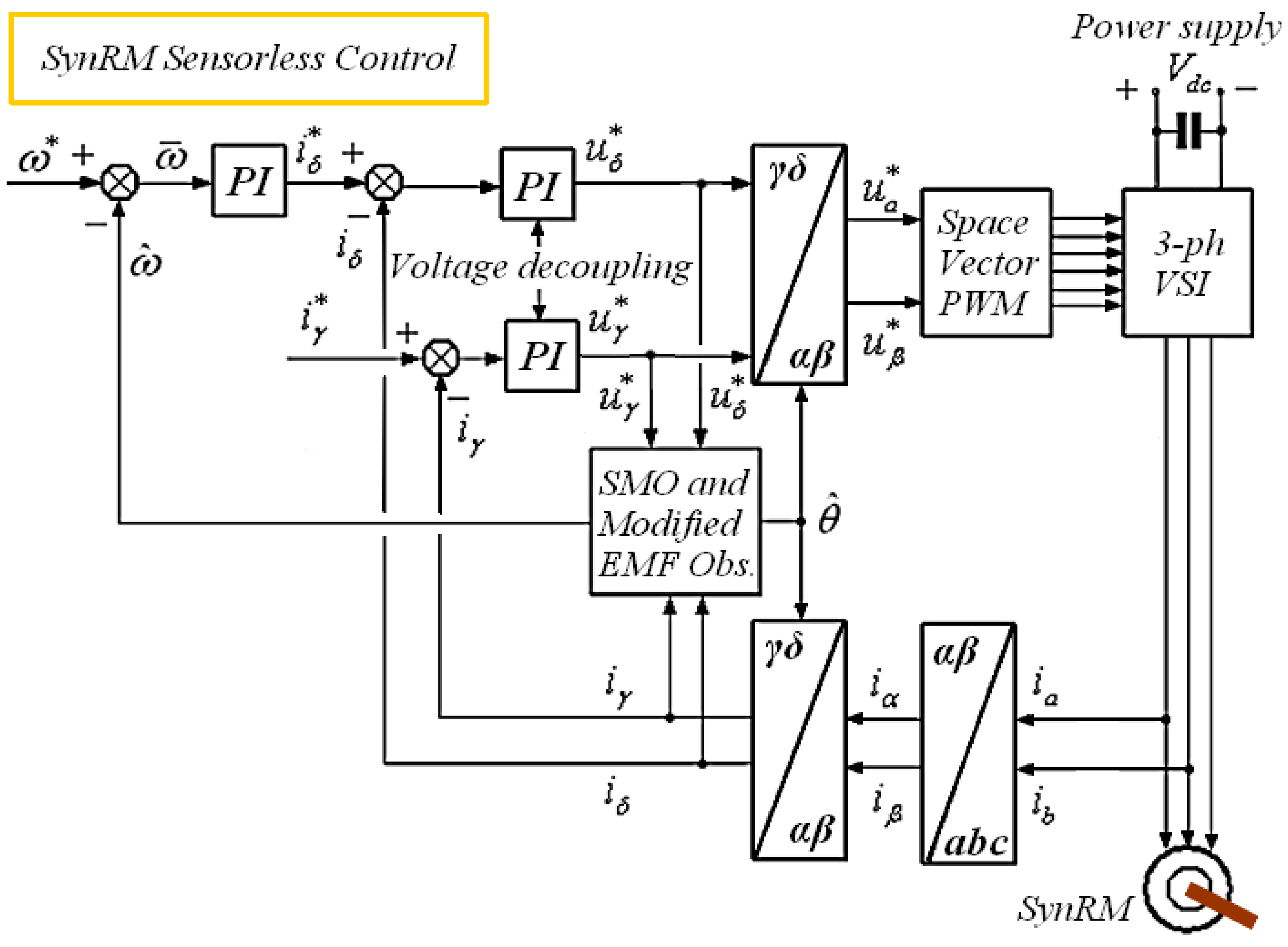
Figure 1. Sensorless control of Synchronous Reluctance Machine (SynRM) based on a sliding mode observer (SMO) for speed and position estimation.
Magnetism 05 00004 g001
Figure 2. The rotor structure of a four-pole SynRM with saliency due to different inductances along the d- and q-axes.
Magnetism 05 00004 g002
Figure 3. Vector analysis considering the SynRM modified rotor flux, λms, in αβ stationary, dq synchronous, and γδ estimated reference frames with α-axis depicting the a-phase magnetic axis.
Magnetism 05 00004 g003
Figure 4. The SynRM model in the γδ reference frame used in implementing the speed and position estimation (Equations (11)–(14)).
Magnetism 05 00004 g004
Figure 5. The formation of the overall observer in a block diagram. (a) The interconnection of partial observers using numbers of equations and (b) the total observer of SynRM in the γδ reference frame, including detailed block diagrams of SMO, Stator Resistance Observer, and Modified EMF Observer.
Magnetism 05 00004 g005
Figure 6. (Left) SynRM and Observer responses during the double stepwise change in the reference speed, from 0 rad/s to 20π rad/s (or 10 Hz) and at t3 = 4 s from 20π rad/s to 0π rad/s, while an external torque of 2 Nm is applied to the SynRM rotor and removed at times t1 = 2 s and t2 = 3 s, respectively: (a) angular speed (real and estimated), (b) angular position (real and estimated), and (c) angle error. (Right) (d) Modified rotor flux of SynRM (real), (e) modified EMF Eδ (estimated), and (f) equivalent control inputs, vγeq and vδeq.
Magnetism 05 00004 g006aMagnetism 05 00004 g006b
Figure 7. (Left) SynRM and Observer responses in the course of two stepwise speed changes from 0 rad/s to 20π rad/s (or 10 Hz) and at t2 = 4 s from 20π rad/s to 0π rad/s, and applying and removing an external torque of 2 Nm at times t1 = 2 s and t2 = 3 s, respectively: (a) stator currents (estimated), (b) stator currents in abc (real), (c) estimated stator currents (Chattering phenomenon). (Right) (d) produced torque, load torque as external disturbance and total torque (real), (e) iγ current error, and (f) iδ current error.
Magnetism 05 00004 g007aMagnetism 05 00004 g007b
Figure 8. (Left) Responses of SynRM as the reference speed is stepwise changed from 0 rad/s to 40π rad/s (or 20 Hz) at t0 = 0 s and from 40π rad/s to −40π rad/s at t3 = 4 s, and an external torque of 4 Nm is applied and removed at t1 = 1 s and t2 = 3 s, respectively: (a) angular speed (real and estimated), (b) angular position (real and estimated), and (c) angle error. (Right) (d) modified rotor flux of SynRM (real), (e) modified EMF Eδ (estimated), and (f) equivalent control inputs, vγeq and vδeq.
Magnetism 05 00004 g008aMagnetism 05 00004 g008b
Figure 9. (Left) Responses of SynRM as the reference is changed stepwise from 0 rad/s to 10π rad/s (or 5 Hz) at t0 = 0 s and from 10π rad/s to −20π rad/s at t3 = 4 s with an external torque TL of 2 Nm initially applied at t1 = 1 s and then removed at t2 =3 s: (a) angular speed (real and estimated), (b) angular position (real and estimated), and (c) angle error. (Right) (d) Modified rotor flux of SynRM (real), (e) modified EMF Eδ (estimated), and (f) equivalent control inputs, vγeq and vδeq.
Magnetism 05 00004 g009
Figure 10. (Left) Responses of SynRM for two stepwise changes in reference speed, from 0 rad/s to 10π rad/s (or 5 Hz) and at t2 = 4 s from 10π rad/s to -20π rad/s, and an external torque TL of 2 Nm applied during the time period from t1 = 1 s to t2 = 3 s: (a) real stator currents in γδ and (b) estimated currents in γδ. (Right) (c) Real stator currents in abc and (d) produced torqueTe, load torque (or external disturbance) TL, and total torque Ttot.
Magnetism 05 00004 g010
Figure 11. Sensorless control of the SynRM implemented using DSP or microcontroller.
Magnetism 05 00004 g011
Table 1. Parameters of Synchronous Reluctance Machine (SynRM).
SymbolQuantityExpressed in SI
PPower4.4 kW
Vl-lLine to line voltage380 V
rsStator resistance2.5 Ω
Ldd-axis inductance0.400 H
Lqq-axis inductance 0.210 H
JMoment of inertia 0.089 kgm2
pMagnetic pole pairs1
ωmMechanical angular speed3000 rpm
Table 2. Gain parameters of Flux/Current Observers (SMO).
SymbolQuantityValue
kγγ-axis gain of SMO20,000
kδδ-axis gain of SMO 20,000
γrgain of stator resistance estimator 75
Table 3. Gain parameters of Modified EMF and Speed Observers.
SymbolQuantityValue
γEgain of modified EMF observer 80
γωgain of angular speed observer400
Disclaimer/Publisher’s Note: The statements, opinions and data contained in all publications are solely those of the individual author(s) and contributor(s) and not of MDPI and/or the editor(s). MDPI and/or the editor(s) disclaim responsibility for any injury to people or property resulting from any ideas, methods, instructions or products referred to in the content.