


Abstract
Soil–structure interaction (SSI) under torsional loading plays a critical role in the dynamic performance of foundations supporting offshore structures and machine foundations. However, existing simplified or semi-analytical approaches often idealize the pile tip boundary and may not adequately capture the frequency-dependent torsional impedance induced by finite soil thickness beneath the pile tip in layered deposits. This study develops a Hamilton-based variational solution for dynamic torsional soil–pile interaction in layered viscoelastic soils by explicitly incorporating a fictitious soil pile (FSP) beneath the pile tip within an energy-consistent framework. Admissible torsional displacement fields for the pile, layered soil, and FSP are adopted to establish a frequency-domain variational functional, and an iterative scheme is used to obtain the convergent frequency-dependent torsional impedance at the pile head. The formulation is verified against an existing semi-analytical solution for piles in layered soils and shows excellent agreement. Parametric results indicate that introducing a finite FSP reduces torsional stiffness and increases damping compared with a rigid base condition, while the thickness and stiffness of the bearing stratum govern the variation in impedance, providing physical insight into torsional SSI in layered ground.
1. Introduction
Soil–structure interaction (SSI) plays a critical role in the performance of deep foundations under dynamic actions such as earthquakes, wind, and machine-induced vibrations [1]. When horizontal loads act eccentrically on the superstructure, single piles and pile groups are subjected to significant torsional moments in addition to shear forces and bending [2]. The resulting torsional soil–pile interaction may strongly influence the stiffness, damping, and rotation demands of foundations supporting bridges, high-rise buildings, transmission towers, offshore platforms, and other infrastructure systems. For large-diameter piles installed in layered soil deposits, the frequency-dependent torsional impedance of the pile–soil system can govern natural frequencies, serviceability, and fatigue performance [3,4,5,6]. Reliable prediction of the torsional response of pile foundations in realistic soil profiles is therefore an important topic.
The torsional behavior of single piles under dynamic loading has been studied extensively as a fundamental mode of soil–structure interaction. Continuum-based formulations established the theoretical basis by combining three-dimensional elastic half-space theory with shear wave propagation to derive analytical or semi-analytical expressions for the torsional dynamic impedance of piles. Classical solutions were developed by Novak [7] and extended by Rajapakse [8] to more general elastic foundation configurations. Subsequently, increasingly realistic ground models were considered, including poroelastic, saturated, and transversely isotropic media [9,10,11], as well as large-diameter pipe piles in viscoelastic saturated and unsaturated soils [12,13]. To better represent natural deposits, non-homogeneous and layered profiles have also been investigated, such as non-homogeneous media [14], radially inhomogeneous soils [15], and inhomogeneous or radially inhomogeneous saturated soils for end-bearing or large-diameter piles [16,17]. More recently, torsional analyses were further extended to unsaturated and disturbed soils considering construction disturbance, anisotropy, and viscoelasticity [18,19,20,21], and nonlinear effects were explored for two-layer soils and soil plug conditions [22,23]. Collectively, these studies demonstrate that layering, inhomogeneity, and nonlinearity can significantly influence the torsional stiffness and damping (impedance) of the pile–soil system.
In contrast to the above continuum formulations, simplified soil–structure interaction models have also been proposed to improve modeling efficiency. In such approaches, the pile is typically idealized as a one-dimensional rod or Timoshenko beam, while the surrounding soil is represented by distributed springs and dashpots or simplified torsional soil wedges. Representative examples include equivalent elastic foundation models for piles in multilayered soils [24], wedged soil formulations for stepped piles [25], and hybrid formulations for pile foundations in layered deposits [26], as well as simplified idealizations adopted for slender foundation-supported structural members under seismic loading [27]. These models offer a favorable balance between accuracy and simplicity for practical applications. Nevertheless, the strong simplification of three-dimensional wave propagation and radiation damping may limit the ability of such models to capture impedance variations that arise from complex layered profiles and realistic pile tip conditions, especially when finite soil thickness beneath the pile tip induces a pronounced frequency-dependent contribution that cannot be adequately represented by overly idealized tip constraints.
To further bridge fidelity and efficiency, energy-based and variational approaches have attracted increasing interest as “quasi-analytical” tools. Nghiem [28,29] proposed efficient torsional solutions and developed a variational formulation for piles in multilayered soils. Wang [30] further presented a Hamilton-based variational solution for an end-bearing pile in a homogeneous viscoelastic half-space, using assumed displacement fields and iterative updating of control parameters. These studies highlight that variational methods can yield compact governing equations, efficient solution procedures, and clear physical interpretation. However, most existing variational and hybrid formulations still rely on idealized pile tip boundary conditions (e.g., rigid, free, or simple elastic springs) and therefore cannot fully represent the frequency-dependent influence of a finite soil layer beneath the pile tip, particularly in the presence of complex layering. Moreover, an energy-consistent formulation that embeds a fictitious soil pile-type representation of the underlying finite tip–soil domain directly into a Hamilton-based variational functional for multilayered viscoelastic soils remains limited. The present study addresses this gap by developing a unified variational framework that explicitly incorporates the soil beneath the pile tip through the fictitious soil pile (FSP) concept in an energy-consistent manner.
To more realistically represent the dynamic action of the soil beneath the pile tip, the fictitious soil pile model has been introduced into axial and torsional vibration analyses of single piles. In this model, a finite portion of the underlying soil is replaced by a “soil pile” segment with the same cross-section as the real pile and material properties representative of the underlying soil. The fictitious soil pile is rigidly bonded to the real pile at their interface, and its dynamic response is used to condense wave propagation and energy reflection in the underlying soil into a frequency-dependent complex impedance at the fictitious pile head. Wu [31,32] applied the FSP concept to the torsional dynamic response of piles in layered soil and to tapered piles with construction disturbance; Li [17,18] extended the idea to radially inhomogeneous and unsaturated soils and proposed a fictitious unsaturated soil pile model for floating piles. These works confirm that the FSP model can effectively handle complex pile tip conditions and reproduce the frequency-dependent impedance associated with finite soil layers. However, existing torsional analyses based on the FSP model are mainly formulated within conventional frequency-domain frameworks, such as transfer matrix or transform-based analytical methods, and focus on closed-form or semi-closed-form expressions for pile head impedance. A unified variational framework that naturally embeds the fictitious soil pile in the energy functional of the pile–soil system is still lacking.
Against this background, the present study develops a variational elastic solution for dynamic torsional soil–pile interaction in layered viscoelastic soils, explicitly incorporating the fictitious soil pile model. Within Hamilton’s principle, a coupled system comprising the main pile segment, the fictitious soil pile, and the surrounding layered soil is constructed, and unified displacement fields are adopted to formulate the strain energy, kinetic energy, and external work of the system. Notably, the fictitious soil pile is embedded directly into the variational functional, rather than being treated as an externally imposed pile tip boundary condition. By condensing the response of the fictitious soil pile into a frequency-dependent complex torsional impedance at the pile tip, the contribution of the underlying soil can be incorporated in an energy-consistent manner. An iterative scheme is then employed to update layer-wise control parameters and obtain convergent solutions for pile rotation, torque distribution, and torsional impedance at the pile head. The proposed formulation thus bridges energy-based variational analysis and fictitious soil pile modeling and provides an efficient tool for analyzing the torsional dynamic response of pile foundations in layered soil deposits.
2. Mathematical Model
2.1. Problem Description and Basic Assumptions
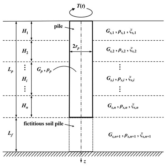
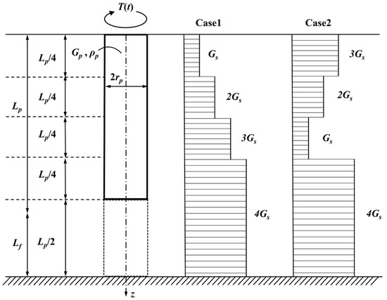
Consider a vertical cylindrical pile of radius rp and length Lp embedded in a layered viscoelastic soil deposit, as illustrated in Figure 1. The pile head is located at the ground surface z = 0 and is subjected to a time-dependent torsional moment T(t). The embedded part of the pile extends from z = 0 to z = Lp. The soil deposit above the pile tip is modeled as n horizontal layers with thicknesses Hi (i = 1, …, n), and the soil beneath the pile tip is represented by a fictitious soil pile of length Lf. The bottom of the FSP at z = Lp + Lf is assumed to be perfectly fixed.
Figure 1.
A schematic of a single pile with a fictitious soil pile in layered soil under dynamic torsional loading.
A cylindrical coordinate system (r, θ, z) is adopted, with the z-axis coinciding with the pile axis in a positive downward manner from the ground surface. The problem is assumed to be axisymmetric, and the soil and pile are treated as linear viscoelastic continua. The following basic assumptions are made:
- 1.
- The pile is an isotropic, homogeneous, linearly viscoelastic solid with shear modulus Gp and mass density ρp.
- 2.
- Each soil layer is isotropic and linearly viscoelastic, characterized by its shear modulus Gs,i, mass density ρs,i, and damping ratio ξs,i (i = 1, …, n + 1). Soil damping is modeled by a complex shear modulus, Gs,i* = Gs,i(1 + 2jξs,i), where Gs,i = Es,i/{2(1 + νs,i)}, Es,i, and νs,i are the Young’s modulus and Poisson’s ratio, respectively, and j = .
- 3.
- The torsional motion is axisymmetric and only the circumferential displacement component u(r, z, t) is considered, whereas the radial and vertical displacements are neglected, i.e., ur = uz = 0; coupling with lateral bending or axial vibration (e.g., due to combined loading or eccentric excitation) is beyond the scope of the present study.
- 4.
- The response is assumed to be harmonic in time with circular frequency ω. The external torque and displacements can therefore be written as T(t) = T0ejωt, where T0 is the torque amplitude.
Notation conventions are as follows. Scalars are written in italic font, whereas vectors and matrices are denoted by bold symbols (e.g., a, M, f). Unless otherwise stated, frequency-domain quantities are complex-valued. The superscript “*” is used to indicate complex material moduli introduced to account for viscoelasticity (e.g., Gs,i* = Gs,i(1 + 2jξs,i); it is not used to denote complex conjugation.
Under these assumptions, the objective is to derive a variational formulation for the torsional vibration of the pile–soil system, including the fictitious soil pile beneath the pile tip, and to obtain the pile head torsional response and dynamic impedance as functions of the excitation frequency.
2.2. Layered Soil Profile and Fictitious Soil Pile Model
The soil surrounding the pile is divided into n horizontal layers above the pile tip and one equivalent layer beneath the tip, as shown in Figure 1. The thickness of the i-th soil layer above the tip is denoted by Hi (i = 1, …, n). Within each layer, the soil properties are taken as constant: shear modulus Gs,i, density ρs,i, and damping ratio ξs,i. The corresponding complex shear modulus is Gs,i* as defined above.
The soil beneath the pile tip is represented by a fictitious soil pile of length Lf. The FSP has the same radius rp as the real pile and is perfectly bonded to the pile at z = Lp. Its material parameters are chosen to be those of the underlying (n + 1)-th soil layer. The bottom of the FSP at z = Lp + Lf is assumed to be fully fixed in torsion, so that the circumferential displacement and rotation vanish at this depth.
In this way, the finite-thickness soil beneath the pile tip is modeled by the FSP, and its dynamic contribution to the torsional response can be condensed into a frequency-dependent complex impedance at z = Lp, which will serve as the effective boundary condition at the base of the real pile.
2.3. Displacement Fields and Energy Expressions
In this section, the torsional displacement functions of the pile, the layered soil, and the fictitious soil pile are first introduced and the meaning of each parameter is clarified. Based on these assumed displacement fields, the shear strain energy, the kinetic energy, and the work carried out by the external torsional loading are derived, and the total energy functional of the coupled pile–soil–FSP system is established.
2.3.1. Torsional Displacement Functions of Pile, Layered Soil, and Fictitious Soil Pile
In the cylindrical coordinate system (r, θ, z), only the circumferential displacement component u(r, z, t) is considered, while the radial and vertical displacements are neglected (ur = uz = 0). For the main pile segment (0 ≤ z < Lp, 0 ≤ r ≤ rp), warping of the circular cross-section in torsion is neglected, and the circumferential displacement is expressed in terms of the cross-sectional rotation function as
where φp(z, t) denotes the torsional dynamic response of the pile cross-section at depth z. Since the soil profile above the pile tip is divided into n layers, the embedded pile is accordingly divided into n segments. Within the i-th soil layer (zi−1 ≤ z ≤ zi), the torsional response of the pile is denoted by φi(z, t), and the circumferential displacement of the pile can be written as
For the surrounding soil in the i-th layer (zi−1 ≤ z ≤ zi, r ≥ rp), the circumferential displacement is assumed to be separable in the axial and radial directions and proportional to the torsional response of the corresponding pile segment:
where ψi(r) is the radial control function (torsional response attenuation function) of the i-th soil layer, describing the decay of the soil torsional response with distance from the pile.
For the fictitious soil pile (FSP) segment below the pile tip (Lp ≤ z ≤ Lp + Lf, 0 ≤ r ≤ rp), the circumferential displacement is assumed to have the same form as that of the main pile:
where φf(z, t) is the torsional response function of the fictitious soil pile segment.
2.3.2. Shear Strain, Stress, and Strain Energy
Based on the displacement function u(r, z, t), the non-zero shear strain components in the pile and soil are
For each domain (the main pile, the i-th soil layer, and the fictitious soil pile), the shear stresses are related to the shear strains through the linear viscoelastic constitutive law
where the superscript (d) denotes the corresponding domain, and Gd* is the complex shear modulus: Gp for the main pile, Gs,i* for the i-th soil layer, and Gf* for the fictitious soil pile segment.
The total shear strain energy U of the coupled pile–soil–FSP system is the sum of the contributions from the main pile, all soil layers, and the FSP:
where Vp, Vs,i, and Vf denote the volumes of the main pile, the i-th soil layer surrounding the pile, and the fictitious soil pile segment, respectively.
Substituting the assumed displacement fields (2)–(4) into Equation (5) and then into Equation (7) and integrating the circumferential angle θ ∈ [0, 2π], the strain energy can be reduced to one-dimensional integrals with respect to z and radial integrals with respect to r. For the main pile, the strain energy can be written as
where Jp = πrp4/2 is the polar moment of inertia of the pile cross-section.
For the surrounding soil in the i-th layer, the strain energy of that layer becomes
To simplify the notation, the following radial integrals are introduced for the i-th soil layer:
With these definitions, Equation (9) can be written in the compact form
Similarly, the strain energy of the fictitious soil pile segment is
Combining Equations (8), (12), and (13), the total shear strain energy of the system can be expressed as
Here, ks,i and ts,i are the equivalent soil stiffness coefficients of the i-th layer associated with the torsional response φi(z) and its axial derivative, respectively, and are explicitly defined by the radial integrals (10) and (11).
2.3.3. Kinetic Energy and Work of External Torsional Loading
In the time domain, the rotational kinetic energy of the system is also expressed as the sum of the contributions from the main pile, all soil layers, and the fictitious soil pile. For the main pile and the FSP, using the displacement fields (2) and (4), their kinetic energies are
For the surrounding soil in the i-th layer, the kinetic energy is
Introducing the equivalent added mass coefficient of the i-th soil layer as
Equation (17) can be rewritten in a compact form as
Therefore, the total kinetic energy of the system is given by
The work carried out by the external torsional loading at the pile head is associated with the rotation of the pile head φ1(0, t), and the complex work term is given by
2.4. Governing Equations Derived from Hamilton’s Principle
Based on Hamilton’s principle, the motion of the coupled pile–soil–FSP system between times t1 and t2 satisfies
where δ(·) is the variational operator, and t1 and t2 are the times at which the configuration of the system is supposed to be known. Substituting the expressions of U, K, and WT derived in Section 2.3, and taking independent variations with respect to the generalized displacement functions φi(z, t), φf(z, t), and ψi(r), the governing equations of the pile segments and the surrounding soil are obtained.
2.4.1. Pile Differential Equation and Its General Solution
For the main pile segment embedded in the i-th soil layer, variation in the energy functional with respect to φi(z) yields a one-dimensional torsional equilibrium equation of the form
Equation (23) is a linear second-order ordinary differential equation with constant (complex) coefficients. Its general solution in the i-th segment of the main pile can be written as
where Ai and Bi are complex integration constants determined by boundary and interface conditions. The real part of λi controls the exponential decay or growth of the torsional response with depth, while the imaginary part is associated with the oscillatory and damping characteristics induced by the viscoelastic pile–soil interaction.
An equation of the same form as (23)–(25) is obtained for the fictitious soil pile segment with its own material parameters.
2.4.2. Radial Control Equation of Surrounding Soil
Taking the variation in the energy functional with respect to the radial control function ψi(r) of the i-th soil layer leads to the following radial equilibrium equation:
where the decay parameter αi is given by the following:
Here, ls,i is a generalized inertia coefficient of the i-th layer, arising from the kinetic energy term, and is therefore proportional to . The coefficient ns,i represents a generalized shear stiffness contribution associated with the axial variation of torsional deformation through (i.e., the γθz component). The coefficient ms,i is another generalized shear stiffness coefficient related to radial shear deformation (the γrθ component), and it scales the radial control equation. Consequently, αi can be interpreted as a radial attenuation wavenumber and 1/αi as the characteristic radial decay length of torsional motion in the i-th soil layer.
Equation (26) is a modified Bessel differential equation in terms of ψᵢ(r). Imposing the boundary conditions ψᵢ(rₚ) = 1, which enforces compatibility of circumferential displacement at the pile–soil interface, and ψᵢ(∞) = 0, which ensures vanishing soil motion at infinity, the solution can be written as follows:
where K1(·) denotes the first-order modified Bessel function of the second kind. The parameter αi governs the rate at which the displacement in the soil medium decreases with increasing radial distance r.
2.5. Equivalent Impedance of Fictitious Soil Pile and Pile Head Response
The governing equations derived in Section 2.4 are completed by introducing the equivalent torsional impedance of the fictitious soil pile (FSP) at the pile tip and enforcing continuity conditions along the pile axis. In this way, the global torsional response of the pile–soil–FSP system can be expressed in terms of a set of algebraic equations and the pile head torsional impedance can be obtained.
2.5.1. Equivalent Complex Impedance of Fictitious Soil Pile
For the FSP segment, a local coordinate ζ is introduced such that
with ζ = 0 at the pile–FSP interface and ζ = Lf at the bottom of the FSP. The torsional angle in the FSP satisfies the same type of differential equation as in Section 2.4, with the material parameters taken as those of the (n + 1)-th soil layer. Its general solution in the frequency domain can be written as
where λf is the complex eigenvalue of the FSP segment.
The bottom of the fictitious soil pile is assumed to be clamped, so that
Imposing this condition gives
from which we obtain
Hence, the torsional angle in the FSP can be written in single-parameter form as
Therefore, the equivalent complex torsional impedance at the FSP head is
This impedance Zf condenses the stiffness and damping contribution of the underlying soil into a frequency-dependent boundary condition at z = Lp.
2.5.2. Continuity Conditions and Algebraic System
The unknown coefficients in Equation (24) {Ai, Bi} are determined by the boundary and interface conditions. At each interface z = zi(i = 1, …, n − 1), the continuity of rotation and torque requires
At the pile head z = 0, an external torsional moment T0 is applied. The boundary condition can be written as
At the pile tip z = Lp, the torque transmitted into the fictitious soil pile is governed by the equivalent impedance Zf, with
Collecting the 2n unknown coefficients {Ai, Bi} into a vector a, the above boundary and interface conditions can be assembled into a linear algebraic system as
where M(ω) is a complex, frequency-dependent coefficient matrix determined by λi, Zf, and the layer thicknesses, and f is the load vector associated with T0.
2.5.3. Pile Head Torsional Impedance
Once the system M(ω)a = f is solved, the complex rotation at the pile head is obtained from the first segment as
The frequency-dependent torsional impedance at the pile head is then defined as
If needed, a non-dimensional impedance can be introduced by normalizing with respect to GpJp/Lp:
in which the real and imaginary parts of KT represent, respectively, the non-dimensional dynamic stiffness and damping at the pile head.
2.6. Iterative Solution Procedure
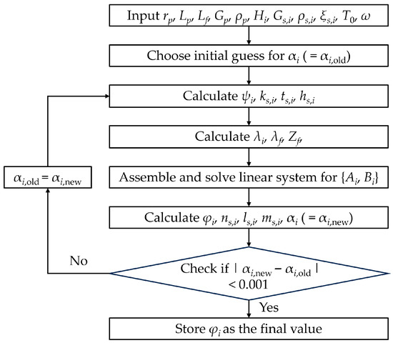
For a given circular frequency ω, the torsional response of the pile–soil–FSP system is obtained by iteratively updating the layer-wise control parameters of the radial control functions until energy consistency is achieved in each soil layer, as illustrated in the flowchart of Figure 2. Starting from an initial guess of the control parameters, the corresponding radial functions, equivalent stiffness and mass coefficients, axial eigenvalues of the pile and fictitious soil pile, and the equivalent impedance at the pile tip are evaluated. The governing equations and all boundary and interface conditions are then assembled into a linear algebraic system for the unknown coefficients of the pile displacement field, from which the torsional response along the pile and pile head rotation are determined.
Figure 2.
A flowchart of the iterative solution procedure for the torsional response of the pile–soil–FSP system.
Based on the converged torsional response, the displacement, strain, and kinetic energy integrals of each soil layer are computed and used to update the control parameters according to the prescribed energy-consistent relations. This procedure is repeated until the absolute difference in the control parameters between two successive iterations is smaller than a specified tolerance (0.001). For the numerical cases examined in this study, the procedure converges rapidly and the above criterion is typically satisfied within three iterations, with no convergence difficulties observed over the considered frequency range and stiffness contrasts. The final converged solution yields the complex torsional impedance at the pile head for the current frequency. By sweeping over the frequency range of interest and using the converged control parameters at one frequency as the initial guess for neighboring frequencies, the complete frequency-dependent torsional impedance of the pile in layered soils can be efficiently obtained.
3. Verification
To verify the accuracy of the proposed variational elastic solution with the fictitious soil pile model, a comparative example is carried out against the approach of Nghiem [29]. In that study, a single vertical circular pile is analyzed by using an energy-based method without using a fictitious soil pile, and the pile head torsional impedance is obtained for several hypothetical layered soil profiles. The present model adopts exactly the same geometric and material properties for the pile–soil system so that any differences in the response can be attributed solely to the modeling assumptions. The basic properties of the pile and the reference soil are summarized in Table 1.
Table 1.
Geometric and material properties used in validation examples.
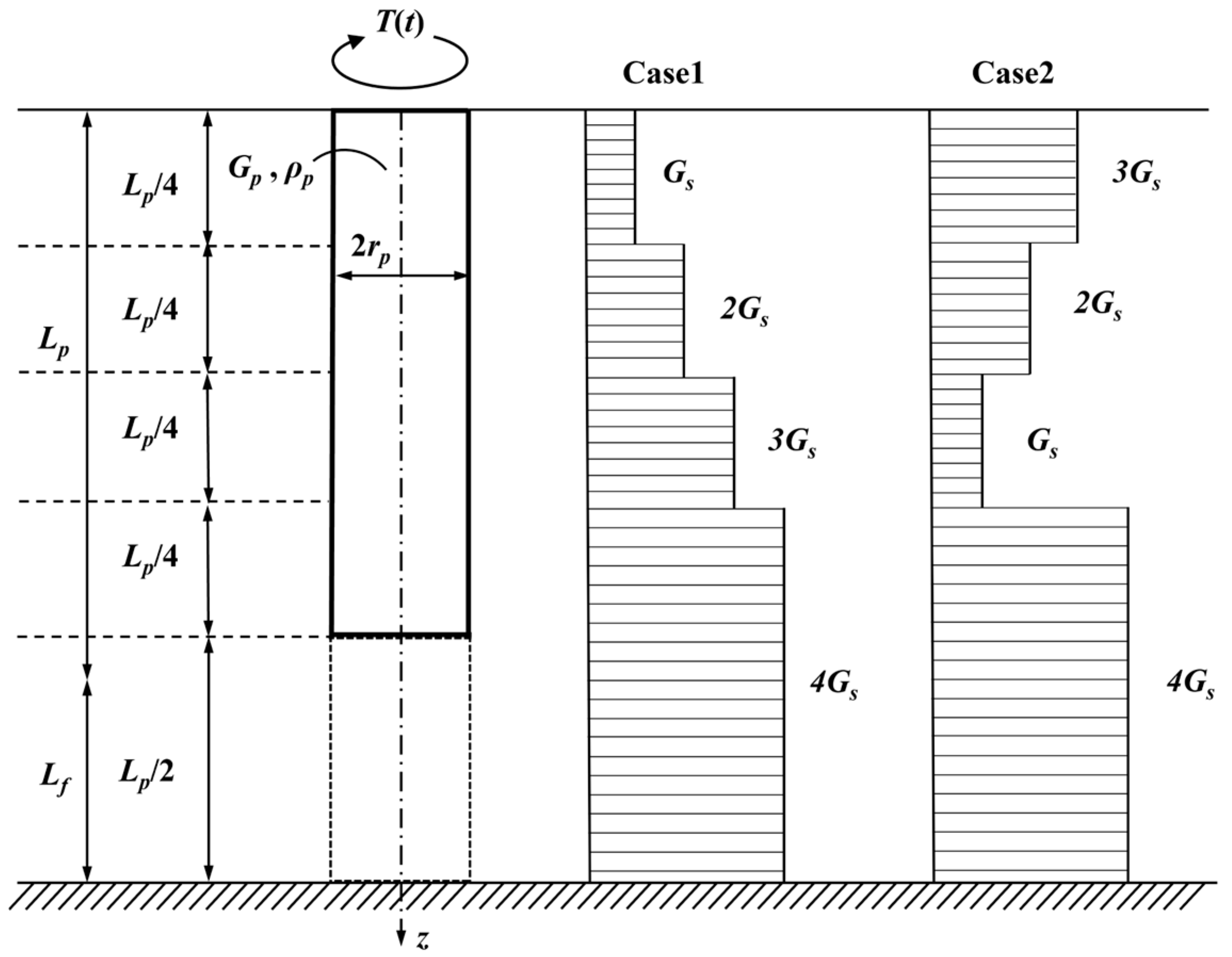
In the parametric study of Nghiem [29], three hypothetical inhomogeneous soil configurations were considered for a pile with length Lp = 20 m and radius rp = 0.5 m embedded in soil. The shear modulus of each soil layer is expressed as a multiple of a reference value Gs. Among these, Case 1 and Case 2 are selected here for validation. In Case 1, the soil stiffness increases monotonically with depth, with four layers of equal thickness Lp/4 and shear moduli Gs, 2Gs, 3Gs, and 4Gs. In Case 2, the upper three layers have moduli 3Gs, 2Gs, and Gs, overlying the same stiff base layer with modulus 4Gs. The corresponding soil profiles for the two cases are illustrated in Figure 3.
Figure 3.
Soil profiles adopted in validation examples based on Nghiem [29].
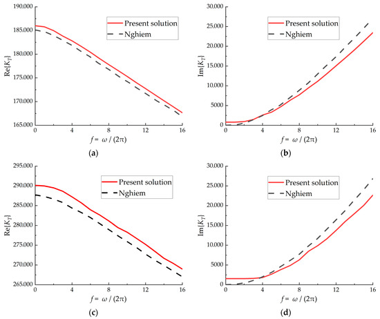
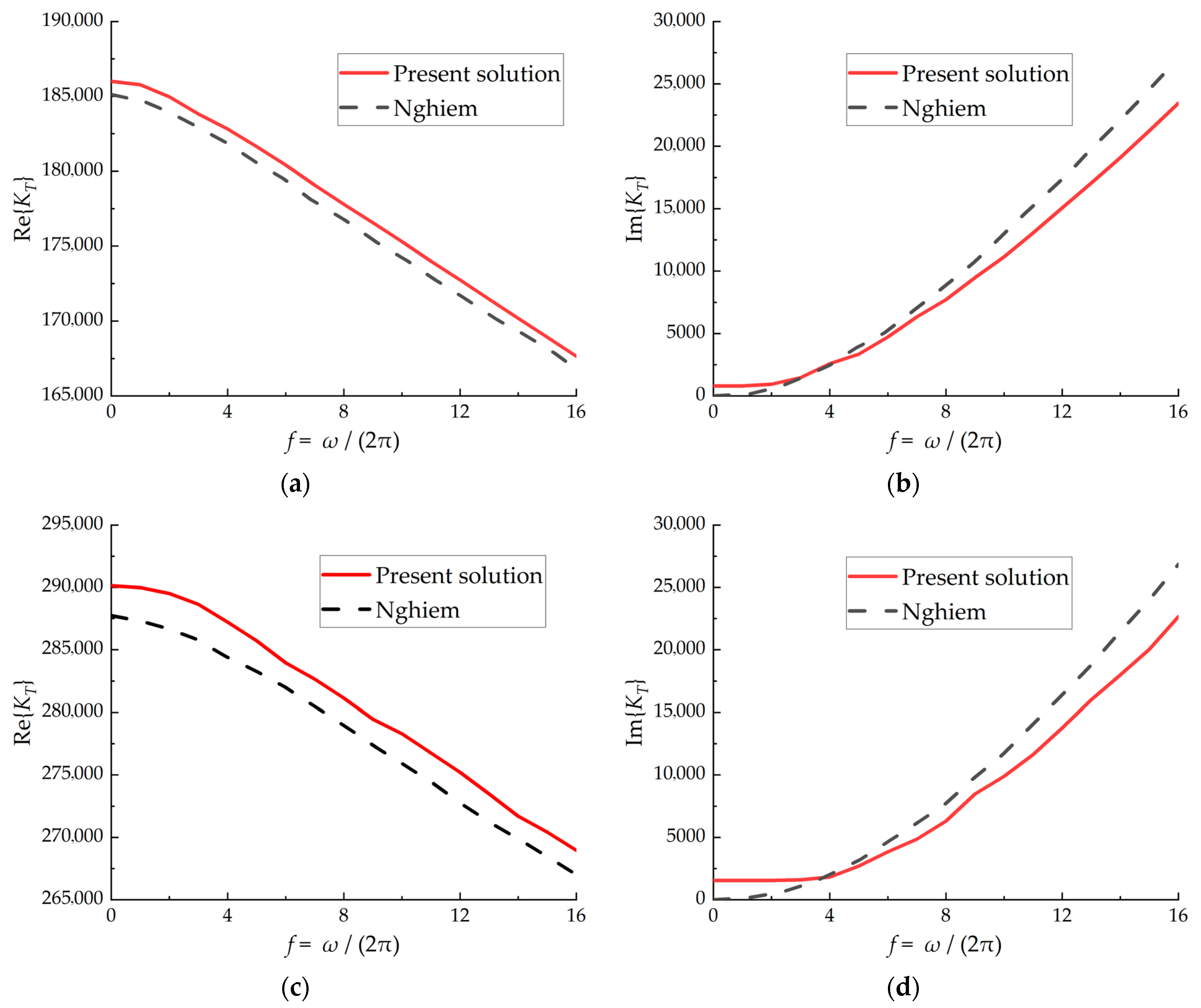
For each frequency f in the range considered by Nghiem, the torsional response of the pile–soil–FSP system is computed using the iterative procedure described in Section 2.6, and the corresponding pile head torsional impedance KT(ω) is obtained. Figure 4 compares the frequency-dependent torsional impedance at the pile head obtained by using the present method with the corresponding results reported by Nghiem for Cases 1 and 2. In both cases, the real part of the impedance (dynamic stiffness) and the imaginary part (equivalent damping) predicted by using the present method agree very well with those of Nghiem over the whole frequency range. Only small deviations are observed at higher frequencies, which can be attributed to the different treatments of wave propagation in the soil and the finite discretization of the soil profile in the present implementation. Overall, the excellent agreement of the stiffness and damping curves confirms that the proposed variational formulation with the fictitious soil pile model can accurately reproduce the torsional dynamic response of a pile in multilayered soils.
Figure 4.
Comparison of pile head torsional impedance between present solution and Nghiem [29] for layered soil profiles: (a) real part of KT for Case 1; (b) imaginary part of KT for Case 1; (c) real part of KT for Case 2; and (d) imaginary part of KT for Case 2.
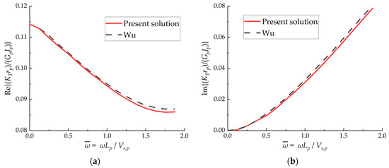
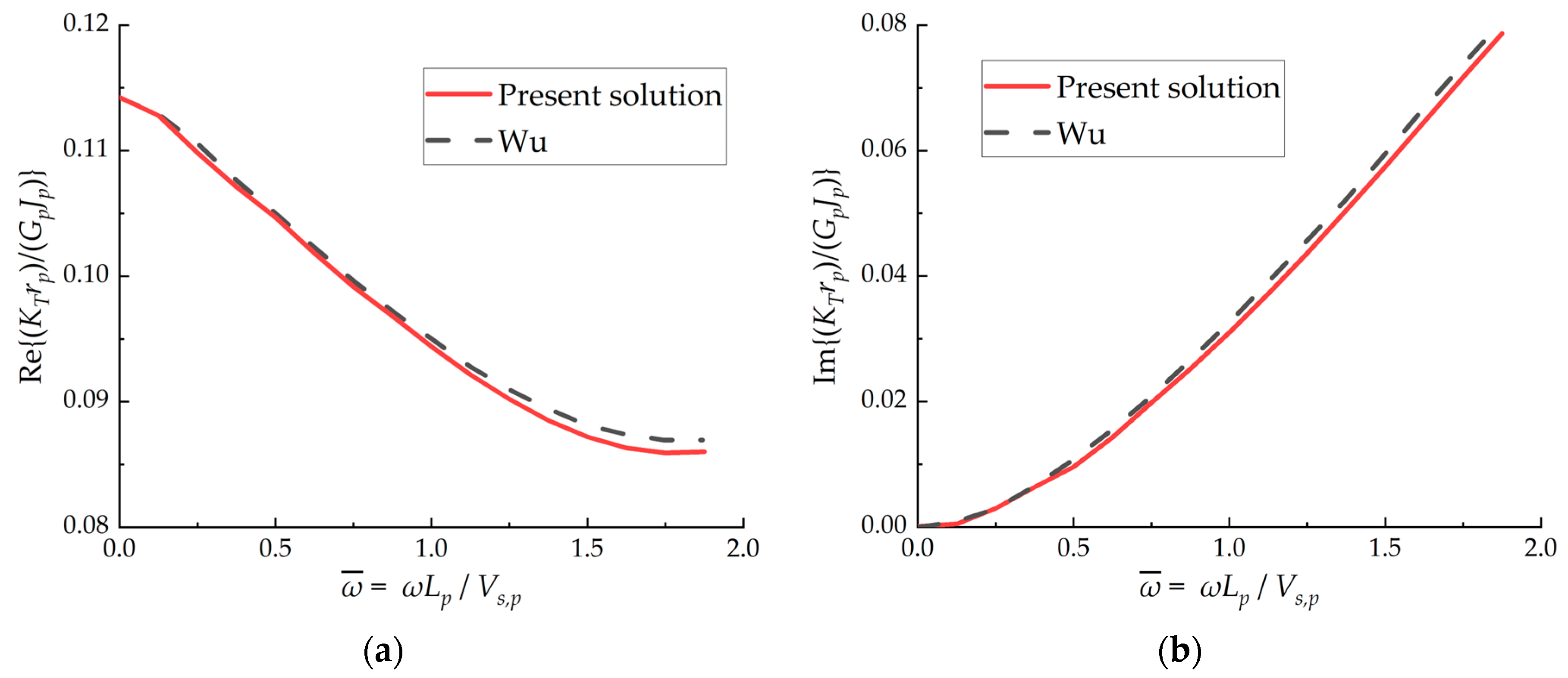
To further verify the correctness of the fictitious soil pile component, an additional comparison is carried out against the FSP-based solution of Wu [32] for a two-layer support model configuration. Wu derived the response using a semi-analytical formulation based on Laplace-domain wave equations and the separation of variables for a layered medium. In that study, the pile–soil system is decomposed into two layers (the pile and the pile-end soil), where the soil beneath the pile tip is represented by an FSP resting on rigid bedrock, and the pile head torsional impedance is reported in dimensionless form. The present model adopts the same parameters: Lp = 10 m, rp = 0.5 m, ρp = 2500 kg/m3, and shear wave velocity Vs,p = 2500 m/s for the pile; ρs = 1800 kg/m3 and Vs,s = 120 m/s for the surrounding soil; and Lf = 0.5 m, ρf = 2000 kg/m3 and Vs,f = 200 m/s for the pile-end soil layer. The corresponding shear moduli are determined by G = ρVs2. Following Wu [32], the pile head impedance KT(ω) is normalized as (KTrp)/(GpJp) and plotted against the dimensionless frequency ωLp/Vs,p. Figure 5 compares the real and imaginary parts of (KTrp)/(GpJp) predicted by using the present method with the corresponding FSP curves digitized from Wu [32]. Very good agreement is observed over the examined frequency range, providing additional verification of the proposed FSP incorporation.
Figure 5.
Comparison of normalized pile head torsional impedance between present solution and Wu [32]: (a) real part Re{KTrp/(GpJp)}; (b) imaginary part Im{KTrp/(GpJp)}.
4. Parameter Study and Discussion
In this section, the proposed variational formulation with the fictitious soil pile model is further applied to investigate the influence of the soil layer beneath the pile tip on the torsional dynamic response. Unless otherwise stated, a uniform circular pile with length Lp = 20 m and radius rp = 1 m is considered. The pile has shear modulus Gp = 1.21 × 10¹⁰ Pa and density ρp = 2500 kg/m3. The surrounding soil along the pile shaft is idealized as two horizontal layers: the upper layer has thickness H1 = 10 m and shear modulus Gs,1 = 2 × 10⁶ Pa, while the second layer has thickness H2 = 10 m and shear modulus Gs,2 = 3Gs,1. The soil density is taken as ρs = 2000 kg/m3 and a constant damping ratio ξs = 0.05 is adopted for all layers. The fictitious soil pile represents the soil beneath the pile tip and its properties are varied to study the effects of the thickness and stiffness of the underlying soil. For convenience, the frequency is presented in terms of the physical frequency f(Hz), while the torsional impedance is normalized by a reference stiffness GpJp/Lp, and the pile head torsional impedance is shown in terms of the real and imaginary parts of KT(ω).
4.1. The Effect of the Thickness of the Soil Layer Beneath the Pile Tip
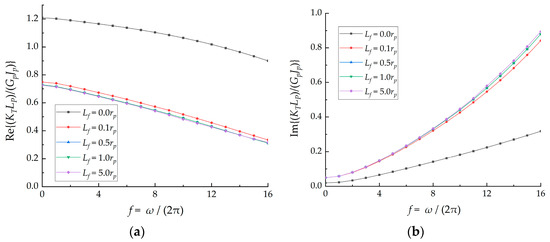
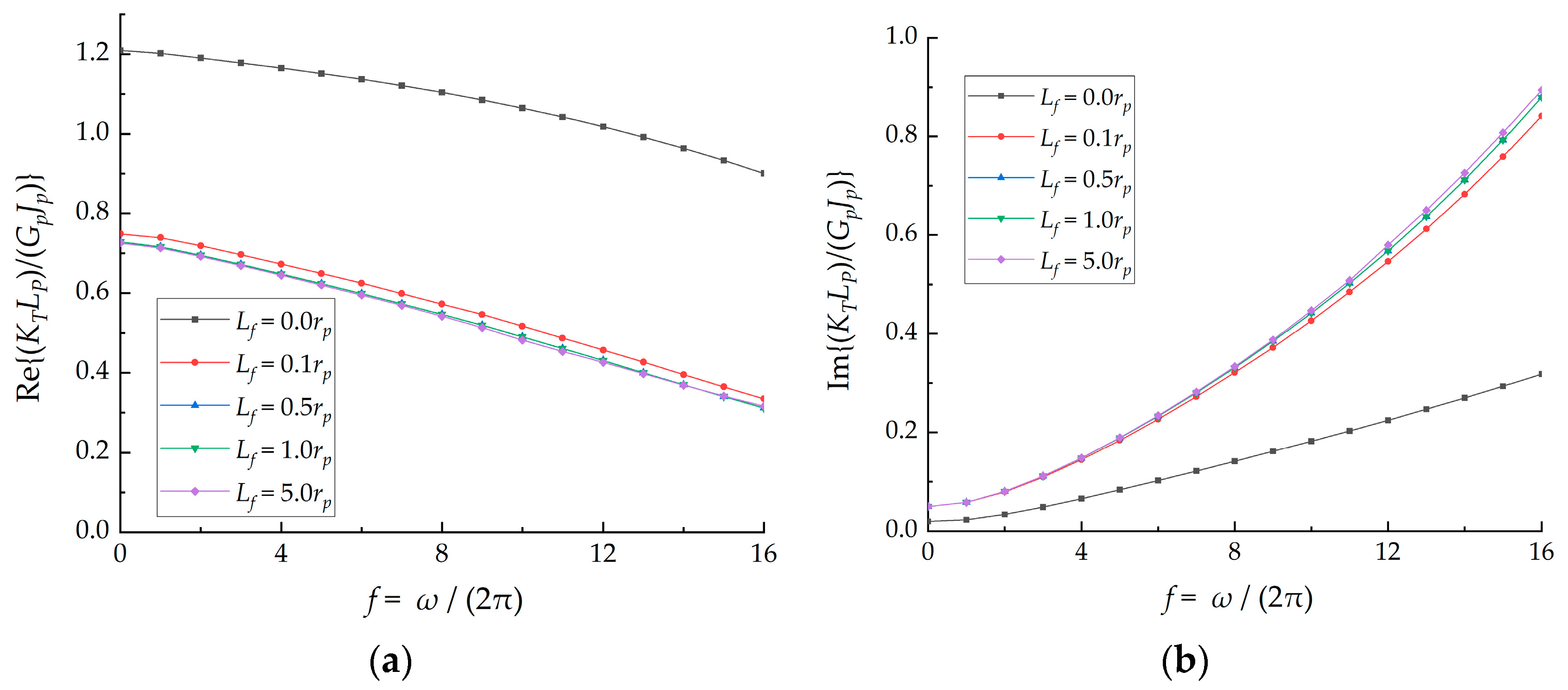
First, the influence of the thickness of the soil layer beneath the pile tip is examined. The shear modulus of the FSP is fixed as Gf = 3Gs,1, while its thickness Lf is varied. Five cases are analyzed: Lf = 0 (no fictitious soil pile, pile tip directly resting on a rigid base), and Lf = 0.1rp, 0.5rp, 1.0rp, and 5.0rp. Figure 6 illustrates the effects of Lf on the real and imaginary parts of the pile head torsional impedance.
Figure 6.
The effect of the thickness of the fictitious soil pile on the normalized pile head torsional impedance: (a) Re{KTLp/(GpJp)} of real part and (b) Im{KTLp/(GpJp)} of imaginary part for different values of Lf.
The results show that the thickness of the soil layer beneath the pile tip has a clear influence on both the real and imaginary parts of the normalized pile head torsional impedance. When Lf = 0, without a fictitious soil pile, the pile behaves as if it were fixed on a rigid base and exhibits the largest low-frequency stiffness and the smallest damping. As Lf increases, the underlying soil becomes more deformable, leading to a noticeable reduction in the normalized stiffness and a corresponding increase in the imaginary part of KT, especially at higher frequencies. For relatively small fictitious soil piles (Lf = 0.1rp), the curves of both the real and imaginary parts are already very close to those for thicker underlying soil layers, and further increases in Lf (0.5rp ≤ Lf ≤ 5.0rp) mainly cause minor adjustments of the stiffness and damping. For sufficiently large Lf, the curves tend to stabilize, indicating that beyond a certain depth, the additional underlying soil has only a limited effect on the pile head torsional impedance.
4.2. The Influence of the Stiffness of the Soil Layer Beneath the Pile Tip and Soft Interlayers
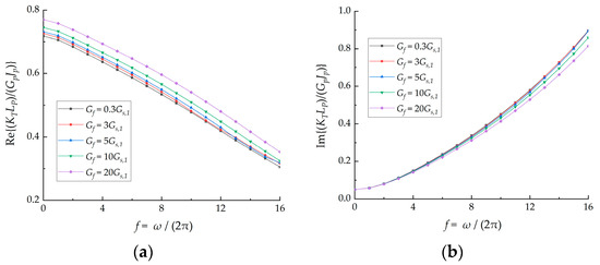
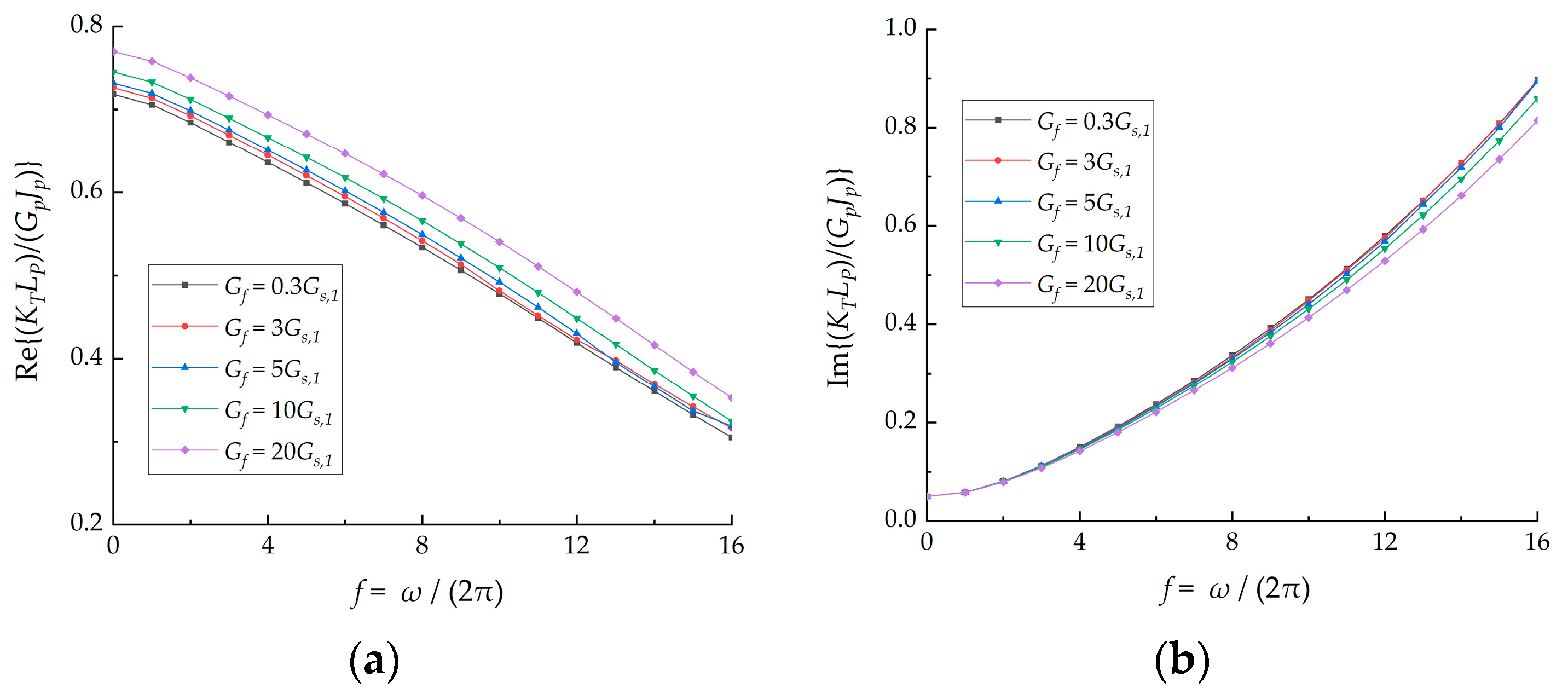
Next, the influence of the stiffness of the soil layer beneath the pile tip is investigated, with particular emphasis on the possible presence of a soft interlayer beneath the pile. In this series of analyses, the FSP thickness is kept constant as Lf = 2.0 m, while its shear modulus Gf is varied relative to the reference value Gs,1. Five representative cases are considered: Gf = 0.3Gs,1, 3Gs,1, 5Gs,1, 10Gs,1, and 20Gs,1. The case with Gf = 0.3Gs,1 represents a significantly soft layer directly beneath the pile tip, whereas Gf = 10Gs,1 and 20Gs,1 correspond to very stiff underlying soil or rock.
The influence of the stiffness of the soil layer beneath the pile tip is illustrated in Figure 7. The real part of the normalized pile head torsional impedance in Figure 7a shows that increasing Gf leads to a moderate increase in stiffness over the whole frequency range, with the largest differences occurring at low frequencies. The soft underlying layer (Gf = 0.3Gs,1) yields the smallest stiffness, but its curve remains close to those for Gf = 3Gs,1 and 5Gs,1, indicating that the overall torsional stiffness is still dominated by the shaft soil layers. The imaginary part in Figure 7b exhibits an opposite but similarly moderate trend: a softer underlying soil produces slightly larger damping, whereas increasing Gf gradually reduces the imaginary part of KT, particularly at higher frequencies. Overall, these results suggest that, for the range of stiffness contrast considered here, the presence of a soft layer directly beneath the pile tip has a noticeable but not dramatic effect on the normalized torsional stiffness and damping; only when the underlying soil becomes very stiff does the pile head impedance significantly approach that of a pile embedded in a rigid base.
Figure 7.
The effect of the shear modulus of the fictitious soil pile on the normalized pile head torsional impedance: (a) Re{KTLp/(GpJp)} of real part and (b) Im{KTLp/(GpJp)} of imaginary part for different values of Gf.
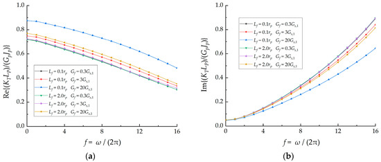
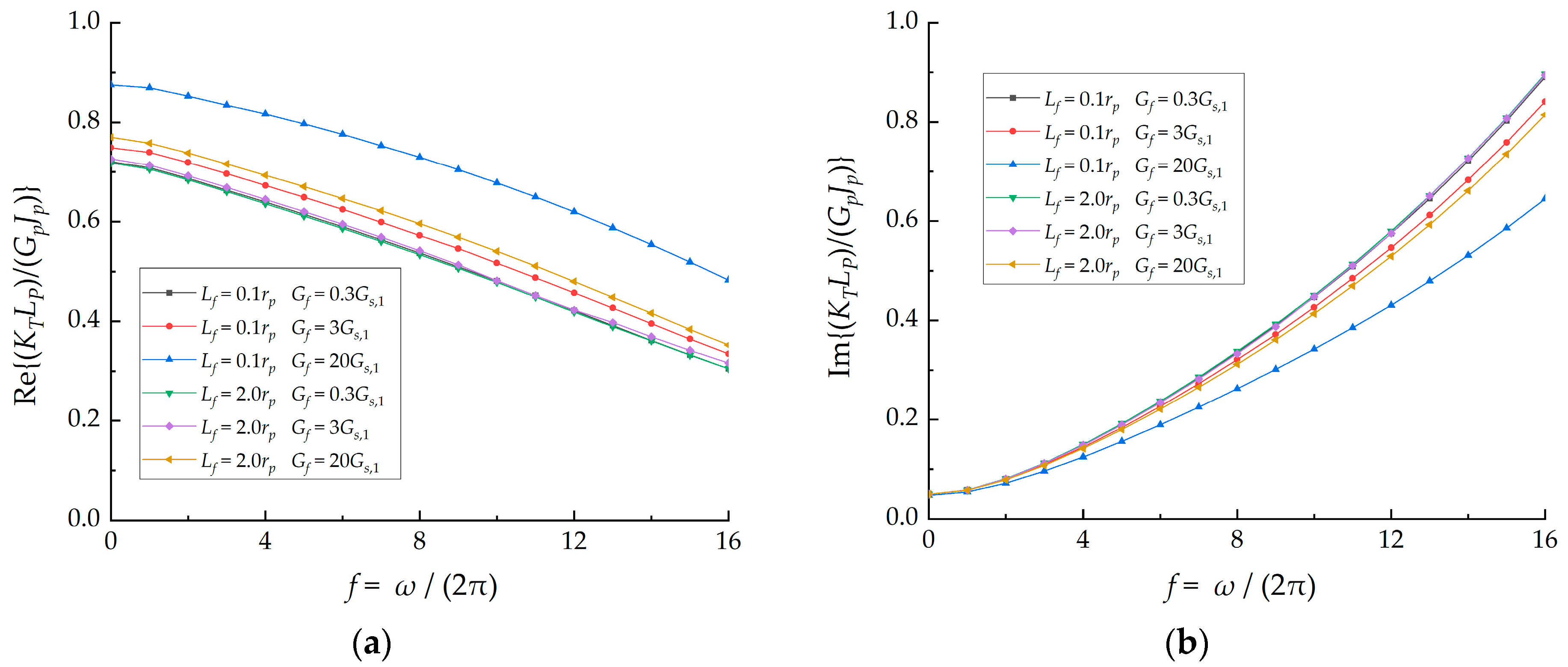
To examine coupling effects between the thickness and stiffness of the soil layer beneath the pile tip, an additional set of analyses is performed in which the FSP thickness Lf and shear modulus Gf are varied simultaneously, while all other parameters remain unchanged. Two representative thicknesses are considered, Lf = 0.1rp and 2rp, and for each thickness three stiffness levels are examined, Gf = 0.3Gs,1, 3Gs,1, and 20Gs,1, resulting in six combined cases. The corresponding normalized pile head torsional impedance is shown in Figure 8. The results show that the sensitivity to stiffness contrast depends on the thickness of the underlying layer. When the underlying layer is very thin (Lf = 0.1rp), varying Gf leads to clearly separated impedance curves, particularly for the stiff case Gf = 20Gs,1. In contrast, for a thicker underlying layer (Lf = 2rp), the curves for Gf = 0.3Gs,1 and 3Gs,1 become almost indistinguishable, and noticeable differences are mainly observed only when the underlying layer is very stiff. Comparing the two thicknesses further indicates a coupling between Lf and Gf: increasing Lf has only a minor effect for soft-to-moderate underlying layers, whereas for a very stiff underlying layer it reduces the real part and increases the imaginary part of the impedance, especially at higher frequencies.
Figure 8.
Coupled effects of the thickness Lf and shear modulus Gf of the fictitious soil pile on the normalized pile head torsional impedance: (a) Re{KTLp/(GPJp)} of real part and (b) Im{KTLp/(GpJp)} of imaginary part for six combined cases (Lf = 0.1rp, 2rp; Gf = 0.3Gs,1, 3Gs,1, 20Gs,1).
5. Conclusions
A variational elastic solution has been developed for the torsional dynamic response of a single pile in layered viscoelastic soils, explicitly incorporating a fictitious soil pile beneath the pile tip. Based on Hamilton’s principle, unified displacement fields are assumed for the pile, surrounding soil, and FSP, from which the strain energy, kinetic energy, and external work are formulated to derive one-dimensional governing equations for the pile and radial control equations for the soil layers. The soil below the pile tip is represented by the FSP, whose response is condensed into a frequency-dependent complex torsional impedance at the pile–soil interface. An energy-consistent iterative procedure is used to update the layer-wise control parameters and to obtain the frequency-dependent pile head torsional impedance. Verification against an existing variational solution for piles in multilayered soils shows very good agreement for both the real and imaginary parts of the pile head impedance over the frequency range considered.
Parametric analyses indicate that the thickness and stiffness of the soil layer beneath the pile tip both affect the torsional impedance. Introducing a finite FSP significantly reduces the torsional stiffness and increases the damping compared with a rigid base condition, whereas increasing the FSP thickness beyond a certain depth leads to only minor changes. Variations in the shear modulus of the underlying soil mainly cause moderate adjustments of the stiffness and damping curves, with softer layers beneath the tip producing lower stiffness and slightly higher damping, while the overall response remains dominated by the shaft soil layers for the stiffness contrasts examined. In addition, the coupled parametric results show that the sensitivity of the pile head impedance to stiffness contrast depends on the thickness of the underlying layer, indicating a non-negligible coupling between thickness and stiffness.
These results demonstrate that the proposed variational formulation with the fictitious soil pile model can efficiently and accurately capture the dynamic torsional soil–pile interaction in layered soils. The method provides a physically transparent and computationally effective tool for evaluating the frequency-dependent torsional impedance of pile foundations, which can be directly incorporated into global dynamic analyses of structures where torsional SSI is of concern. In particular, the pile–soil system can be represented by a complex-valued rotational impedance at the pile head (i.e., an equivalent rotational spring–dashpot in the frequency domain), facilitating straightforward coupling with superstructure models for offshore structures or machine foundations. Future work may extend the present framework to pile groups and to coupled vibration modes (e.g., bending–torsion or axial–torsion coupling) under combined or eccentric loading.
Author Contributions
Conceptualization, H.L. and W.G.; methodology, B.W. and J.S.; software, X.G.; validation, B.W. and G.C.; formal analysis, B.W., H.L. and W.G.; investigation, J.S.; resources, H.L.; data curation, X.G.; writing—original draft preparation, B.W.; writing—review and editing, H.L. and W.G.; visualization, B.W.; supervision, J.S.; project administration, B.W.; funding acquisition, H.L. All authors have read and agreed to the published version of the manuscript.
Funding
This research was funded by the Jiangsu Funding Program for Excellent Postdoctoral Talent, Science and Technology Project of China Power Engineering Consulting Group Co., Ltd. (No. DG2-A01-2024), the Science and Technology Project of China Energy Engineering Group Jiangsu Power Design Institute Co., Ltd. (No. 32-JK-2025-034), the Key Research and Development Program of Shaanxi Province (No. 2022LL-JB-14), and the Qin Chuang Yuan High-level Innovation & Enterprise Talents Program of Shaanxi Province (No. QCYRCXM-2022-114).
Institutional Review Board Statement
Not applicable.
Informed Consent Statement
Not applicable.
Data Availability Statement
The data presented in this study are available on request from the corresponding author. The data are not publicly available due to privacy.
Conflicts of Interest
Bochen Wang, Hongqian Lu, Jiaqing Shu, and Xiaoqing Gu are employees of China Energy Engineering Group Jiangsu Power Design Institute Co., Ltd. Geng Cao is an employee of Shaanxi Huashan Road and Bridge Group Co., Ltd. This study was funded by China Energy Engineering Group Jiangsu Power Design Institute Co., Ltd. The company had no roles in the design of the study; in the collection, analysis, or interpretation of data; in the writing of the manuscript; or in the decision to publish the article. The paper reflects the views of the scientists and not the company.
References
- Gupta, B.K.; Basu, D. Offshore wind turbine monopile foundations: Design perspectives. Ocean Eng. 2020, 213, 107514. [Google Scholar] [CrossRef] [Scilit]
- Kong, J.Q.; Zhang, T.Y.; Gui, F.K.; Qu, X.Y.; Feng, D.J. Dynamic response analysis of anchor piles for marine aquaculture under cyclic loading. J. Mar. Sci. Eng. 2022, 10, 785. [Google Scholar] [CrossRef] [Scilit]
- Labaki, J.; Barros, P.L.; Mesquita, E. A model of the time-harmonic torsional response of piled plates using an IBEM-FEM coupling. Eng. Anal. Bound. Elem. 2021, 125, 241–249. [Google Scholar] [CrossRef] [Scilit]
- Arvan, P.A.; Arockiasamy, M. Energy-Based Approach: Analysis of a Laterally Loaded Pile in Multi-Layered Non-Linear Elastic Soil Strata. Geotechnics 2022, 2, 570–598. [Google Scholar]
- Gupta, B.K. Torsion of end-bearing pile foundations in layered anisotropic geomaterials. Geomech. Geoengin. 2025, 20, 328–344. [Google Scholar] [CrossRef] [Scilit]
- Gupta, B.K. Torsional dynamic response of rigid footings and pile foundations for various end-conditions. Comput. Geotech. 2025, 177, 106857. [Google Scholar]
- Novak, M.; Howell, J.F. Dynamic response of pile foundations in torsion. J. Geotech. Eng. Div. 1978, 104, 535–552. [Google Scholar] [CrossRef] [Scilit]
- Rajapakse, R.K.N.D.; Shah, A.H.; Datta, S.K. Torsional vibrations of elastic foundations embedded in an elastic half-space. Earthq. Eng. Struct. Dyn. 1987, 15, 279–297. [Google Scholar]
- Cai, Y.Q.; Chen, G.; Xu, C.J.; Wu, D.Z. Torsional response of pile embedded in a poroelastic medium. Soil Dyn. Earthq. Eng. 2006, 26, 1143–1148. [Google Scholar] [CrossRef] [Scilit]
- Wang, K.H.; Zhang, Z.Q.; Leo, C.J.; Xie, K.H. Dynamic torsional response of an end bearing pile in saturated poroelastic medium. Comput. Geotech. 2008, 35, 450–458. [Google Scholar] [CrossRef] [Scilit]
- Wang, K.H.; Zhang, Z.Q.; Leo, C.J.; Xie, K.H. Dynamic torsional response of an end bearing pile in transversely isotropic saturated soil. J. Sound Vib. 2009, 327, 440–453. [Google Scholar] [CrossRef] [Scilit]
- Zheng, C.J.; Liu, H.L.; Ding, X.M.; Lv, Y.R. Torsional dynamic response of a large-diameter pipe pile in viscoelastic saturated soil. Int. J. Numer. Anal. Methods Geomech. 2014, 38, 1724–1743. [Google Scholar]
- Ma, W.J.; Shan, Y.; Xiang, K.; Wang, B.L.; Zhou, S.H. Torsional dynamic response of a pipe pile in homogeneous unsaturated soils. Comput. Geotech. 2022, 143, 104607. [Google Scholar] [CrossRef] [Scilit]
- Guo, W.D.; Randolph, M.F. Torsional piles in non-homogeneous media. Comput. Geotech. 1996, 19, 265–287. [Google Scholar] [CrossRef] [Scilit]
- Zhang, Z.Q.; Pan, E. Dynamic torsional response of an elastic pile in a radially inhomogeneous soil. Soil Dyn. Earthq. Eng. 2017, 99, 35–43. [Google Scholar] [CrossRef] [Scilit]
- Li, Z.Y.; Gao, Y.F. Torsional vibration of a large-diameter pipe pile embedded in inhomogeneous soil. Ocean Eng. 2019, 172, 737–758. [Google Scholar] [CrossRef] [Scilit]
- Li, Z.Y.; Gao, Y.F.; Wang, K.H. Torsional vibration of an end bearing pile embedded in radially inhomogeneous saturated soil. Comput. Geotech. 2019, 108, 117–130. [Google Scholar] [CrossRef] [Scilit]
- Li, Z.Y.; Zhao, C.H.; Gao, Y.F.; Wu, W.B.; Wang, K.H.; Zhang, Z.Q. Torsional vibration of a floating pile in radially inhomogeneous unsaturated soil based on the fictitious unsaturated soil pile model. Soil Dyn. Earthq. Eng. 2024, 183, 108812. [Google Scholar] [CrossRef] [Scilit]
- Li, Z.Y.; Zhao, C.H.; Xi, Y.Q.; Jin, N.N.; Gao, Y.F. Torsional vibration of a pile in unsaturated soil considering the construction disturbance. Comput. Geotech. 2024, 172, 106409. [Google Scholar] [CrossRef] [Scilit]
- Liu, C.F.; Chen, Z.L.; Zhao, Y.; Liu, J.; Yi, J.T. Torsional dynamic response of a large-diameter pipe pile in transversely isotropic unsaturated soils considering construction disturbance. Soil Dyn. Earthq. Eng. 2024, 186, 108913. [Google Scholar] [CrossRef] [Scilit]
- Liu, C.F.; Chen, Z.L.; Zhao, Y.; Liu, J.; Yi, J.T.; Qi, D.K. Torsional dynamic response of a pile embedded in layered unsaturated viscoelastic soils. J. Build. Eng. 2025, 100, 111773. [Google Scholar] [CrossRef] [Scilit]
- Zhang, L.Y. Nonlinear analysis of torsionally loaded piles in a two-layer soil profile. Int. J. Geomech. 2010, 10, 65–73. [Google Scholar] [CrossRef] [Scilit]
- Liu, H.; Jiang, G.S.; El Naggar, M.H.; Wu, W.B.; Mei, G.X.; Liang, R.Z. Influence of soil plug effect on the torsional dynamic response of a pipe pile. J. Sound Vib. 2017, 410, 231–248. [Google Scholar] [CrossRef] [Scilit]
- Misra, A.; Saggu, R.; Basu, D.; Chakraborty, T. Analysis of pile subjected to torsion in multi-layered soil. Int. J. Numer. Anal. Meth. Geomech. 2014, 38, 475–492. [Google Scholar] [CrossRef] [Scilit]
- Le, Y.; Wang, N.; Hu, W.T.; Geng, D.X.; Jiang, Y.L. Torsional dynamic impedance of a stepped pile based on the wedged soil model. Comput. Geotech. 2020, 128, 103854. [Google Scholar] [CrossRef] [Scilit]
- Gupta, B.K. A hybrid formulation for torsional dynamic response of pile foundations in a layered soil deposits. Comput. Geotech. 2024, 168, 106115. [Google Scholar] [CrossRef] [Scilit]
- Nascimbene, R.; Brunesi, E.; Sisti, A. Expeditious numerical capacity assessment in precast structures via inelastic performance-based spectra. Heliyon 2024, 10, e39729. [Google Scholar] [CrossRef] [Scilit]
- Nghiem, H.M.; Chang, N.-Y. Efficient solution for a single pile under torsion. Soils Found. 2019, 59, 13–26. [Google Scholar] [CrossRef] [Scilit]
- Nghiem, H.M. Variational approach for torsional dynamic response of a single pile in multi-layered soils. Geomech. Geoengin. 2023, 18, 239–251. [Google Scholar] [CrossRef] [Scilit]
- Wang, B.C.; Zhu, M.X.; Gong, W.M.; Cao, G. Variational elastic solution for an end bearing pile subjected to dynamic torsional loading. Soil Mech. Found. Eng. 2022, 59, 126–133. [Google Scholar] [CrossRef] [Scilit]
- Wu, W.B.; Jiang, G.S.; Lv, S.H.; Huang, S.G.; Xie, B.H. Torsional dynamic impedance of a tapered pile considering its construction disturbance effect. Mar. Georesour. Geotechnol. 2016, 34, 321–330. [Google Scholar]
- Wu, W.B.; Liu, H.; El Naggar, M.H.; Mei, G.X.; Jiang, G.S. Torsional dynamic response of a pile embedded in layered soil based on the fictitious soil pile model. Comput. Geotech. 2016, 80, 190–198. [Google Scholar] [CrossRef] [Scilit]

Disclaimer/Publisher’s Note: The statements, opinions and data contained in all publications are solely those of the individual author(s) and contributor(s) and not of MDPI and/or the editor(s). MDPI and/or the editor(s) disclaim responsibility for any injury to people or property resulting from any ideas, methods, instructions or products referred to in the content. |
© 2026 by the authors. Licensee MDPI, Basel, Switzerland. This article is an open access article distributed under the terms and conditions of the Creative Commons Attribution (CC BY) license.