Article

Concurrent Validity of Depth-Sensor-Based Quantification of Compensatory Movements during the Swing Phase of Gait in Healthy Individuals

1
Graduate School of Health Sciences, Kumamoto Health Science University, 325 Izumi-machi, Kita-ku, Kumamoto 861-5598, Japan
2
Department of Rehabilitation, Kumamoto Health Science University, 325 Izumi-machi, Kita-ku, Kumamoto 861-5598, Japan
3
Department of Physical Therapy, Kumamoto Kinoh Hospital, 6-8-1 Yamamuro, Kita-ku, Kumamoto 860-8518, Japan
4
Department of Rehabilitation, Kumamoto Kinoh Hospital, 6-8-1 Yamamuro, Kita-ku, Kumamoto 860-8518, Japan
5
Department of Physical Therapy, School of Health Science, Tokyo International University, 1-13-1 Matobakita, Kawagoe-shi, Saitama 350-1197, Japan
*
Author to whom correspondence should be addressed.
Biomechanics 2024, 4(3), 411-427; https://doi.org/10.3390/biomechanics4030028
Submission received: 3 April 2024 / Revised: 1 July 2024 / Accepted: 4 July 2024 / Published: 8 July 2024
(This article belongs to the Special Issue Inertial Sensor Assessment of Human Movement)

Abstract

:
The advancement in depth-sensor technology increased the potential for the clinical use of markerless three-dimensional motion analysis (3DMA); however, the accurate quantification of depth-sensor-based 3DMA on gait characteristics deviating from normal patterns is unclear. This study investigated the concurrent validity of the measurements of compensatory movements measured by depth-sensor-based 3DMA compared to those measured by marker-based 3DMA. We induced swing-phase compensatory movements due to insufficient toe clearance by restricting unilateral ankle and knee joint movements in healthy individuals. Thirty-two healthy young adults (nineteen males, aged 20.4   ±   2.0 years, height 164.4   ±   9.8 cm, weight 60.0   ±   9.3 kg [average ± standard deviation]) walked the 6 m walkway in slow speed, very slow speed, and knee–ankle–foot orthosis (KAFO; participants wore KAFOs on the right leg) conditions. Gait kinematics were measured with marker-based and depth-sensor-based 3DMA systems. The intraclass correlation coefficient (ICC3,1) was used to measure the relative agreement between depth-sensor-based and marker-based 3DMA and demonstrated good or moderate validity for swing-phase compensatory movement measurement. Additionally, the ICC2,1 measured absolute agreement between the systems and showed lower validity than the ICC3,1. The measurement errors for contralateral vaulting, trunk lateral flexion, hip hiking, swing-side hip abduction, and circumduction between instruments were 0.01 m, 1.30°, 1.99°, 2.37°, and 1.53°, respectively. Depth-sensor-based 3DMA is useful for determining swing-phase compensatory movements, although the possibility of missing a slight measurement error of 1–2° must be considered.

1. Introduction

The decreased walking speed in post-stroke patients is attributed to functional impairments, including motor paralysis, muscle weakness, spasticity, and sensory disturbance. Stroke-induced decreased walking speed is a serious problem in daily life, causing reduced quality of life and limited social participation [1,2,3,4]. Perry et al. revealed that the walking speeds of household-, limited community-, and community-walker post-stroke patients are <0.4, 0.4–0.8, and >0.8 m/s, respectively [5]. Similarly, Fulk et al. [6] indicated that the cutoff value for discriminating between household and community walkers is a comfortable walking speed of 0.49 m/s. Additionally, 43.08% (190/441) of post-stroke patients are household walkers, indicating that a large number of these patients are unable to walk independently outside the home [6]. Therefore, improving walking speed is crucial in post-stroke gait rehabilitation.
Gait training has helped improve walking speed. Treadmill gait training for community-dwelling post-stroke patients has improved walking speed by increasing ankle plantar flexion moment during the paretic stance phase [7]. Conversely, Patterson et al. [8] revealed no improvement in step-length asymmetry and swing-phase time asymmetry between the paretic and nonparetic sides despite walking speed improvement by gait training. This result indicates that walking speed improvement is attributed not only to the enhancement of functional impairment on the paretic side but also to an increased compensatory movement by the nonparetic side [8]. Spatiotemporal parameter asymmetry during gait was associated with increased energy costs during gait [9] and reduced bone density in the femoral neck of the paretic side [10]. Therefore, the gait pattern assessment findings should be considered when providing gait rehabilitation to post-stroke patients to improve walking speed and prevent secondary disability.
Typical gait measures include lower limb circumduction, hip hiking, and trailing limb angle [11,12,13]. Given that these measures are calculated from the relative distance of each joint position and angle of each segment, quantifying the movement of body landmarks during gait is necessary. The gold standard method for quantifying the movement of body landmarks is marker-based optical three-dimensional motion analysis (3DMA), which uses multiple infrared cameras to measure the 3D coordinates of reflective markers attached to the body landmarks [11,12,13]. This method accurately measures the 3D coordinates of the landmarks; thus, marker-based 3DMA evaluates detailed gait characteristics [11,12,13]. However, the need for expensive measurement equipment and the burden of attaching numerous reflective markers to the body during measurements limit its use in clinical practice [14]. Advancement in depth-sensor technology for quantitative gait pattern assessment can solve the aforementioned problem in clinical practice [15,16]. Azure Kinect, a typical markerless 3DMA system based on depth-sensor technology, captures the contour and surface irregularities of a subject using a depth sensor and uses machine learning-based skeletal recognition technology to process this depth image. This process allows the estimation of the 3D coordinates of body landmarks [17]. Thus, Azure Kinect is advantageous for clinical implementation due to the elimination of the need to attach reflective markers, although it may provide less accurate measurements compared to the marker-based 3DMA system.
The concurrent validity of depth-sensor-based 3DMA, measured against marker-based 3DMA, for measuring spatiotemporal and kinematic parameters during steady-state gait in healthy individuals has been previously investigated [18,19]. A good concurrent validity in the depth-sensor-based assessment of spatiotemporal variables and each lower limb joint angle in the sagittal plane, except for the ankle joint angle, was reported [19]. Conversely, the accuracy of measurement of the deviation of abnormal gait patterns from normal patterns using depth-sensor-based 3DMA is unclear. Decreased knee flexion and ankle dorsiflexion during the paretic swing phase reduce toe clearance in post-stroke patients with hemiparesis, which induces compensatory movements during the swing phase, such as hip hiking and circumduction [20]. Although previous studies have assessed the compensatory movements during the swing phase by marker-based 3DMA (Table 1), it is unclear whether these parameters can be assessed by depth-sensor-based 3DMA. These abnormal gait patterns were observed in healthy individuals during gait with knee joint motion restricted by the use of an immobilizing orthosis. Zissmimopoulos et al. [21] have demonstrated that pelvic hiking in healthy individuals with knee braces was significantly larger than that of individuals without knee braces. Akbus et al. [22] have reported that the pelvic hiking during the swing phase in healthy individuals wearing a knee–ankle–foot orthosis (KAFO) was not different from that of post-stroke patients. Thus, we induced an abnormal gait pattern in healthy individuals by directing them to wear a KAFO to their unilateral lower limbs and verified the concurrent validity of the depth-sensor-based assessment.
The present study aimed to investigate the concurrent validity of depth-sensor-based 3DMA for quantifying abnormal gait patterns during the swing phase as compared to a reference marker-based 3DMA among healthy individuals. We hypothesized that depth-sensor-based 3DMA would be effective in quantifying compensatory movements due to insufficient toe clearance. Verifying that depth-sensor-based 3DMA is able to quantify abnormal gait patterns during the swing phase with the equivalent accuracy as the marker-based 3DMA would result in the development of rehabilitation practices based on objective gait assessment.

2. Materials and Methods

2.1. Participants

The present study included 32 healthy young adults (Table 2) and excluded those with musculoskeletal pain, previous lower extremity or trunk surgery, or neurological disease history that could affect motor control.

2.2. Experimental Procedure

Participants were instructed to walk a 6 m walkway five times in each of the slow speed, very slow speed, and KAFO conditions. The cadence and step length were set at 90 bpm and 350 mm, respectively, in the slow condition and 70 bpm and 250 mm, respectively, in the very slow speed condition. We referenced the results of the spatiotemporal variables for post-stroke patients to determine the cadence and step length for each condition [23]. Post-stroke patients walking at speeds ranging from 0.5 to 1.4 km/h (0.14–0.39 m/s) exhibited a mean cadence and paretic step length of 72.72 steps/min and 24.64 cm, respectively. Conversely, those walking at speeds between 1.5 and 2.4 km/h (0.42–0.67 m/s) demonstrated a mean cadence and paretic step length of 91.71 steps/min and 35.72 cm, respectively. Participants in the KAFO condition wore a KAFO (Modular Leg Brace NEO, TOKUDA Prosthetics and Orthotics Mfg Ltd., Kumamoto, Japan) on the right lower limb in addition to performing the tasks in the very slow speed condition. The KAFO was set with the knee and ankle joints in 0° extension and 0° dorsiflexion, respectively. Participants in the cadence control were instructed to step according to an electronic metronome set for each condition. The lengths of the first and second steps at the beginning of gait in the control of step length were indicated by lines tape-marked on the floor, and participants were instructed to maintain this step length. Data collections were conducted after practice using the abovementioned settings before each condition to allow participants to familiarize themselves with the task. After visually confirming that the participant was stepping onto the electronic metronome, the examiner verbally asked the participant if they were familiar with the task.

2.3. Data Collection

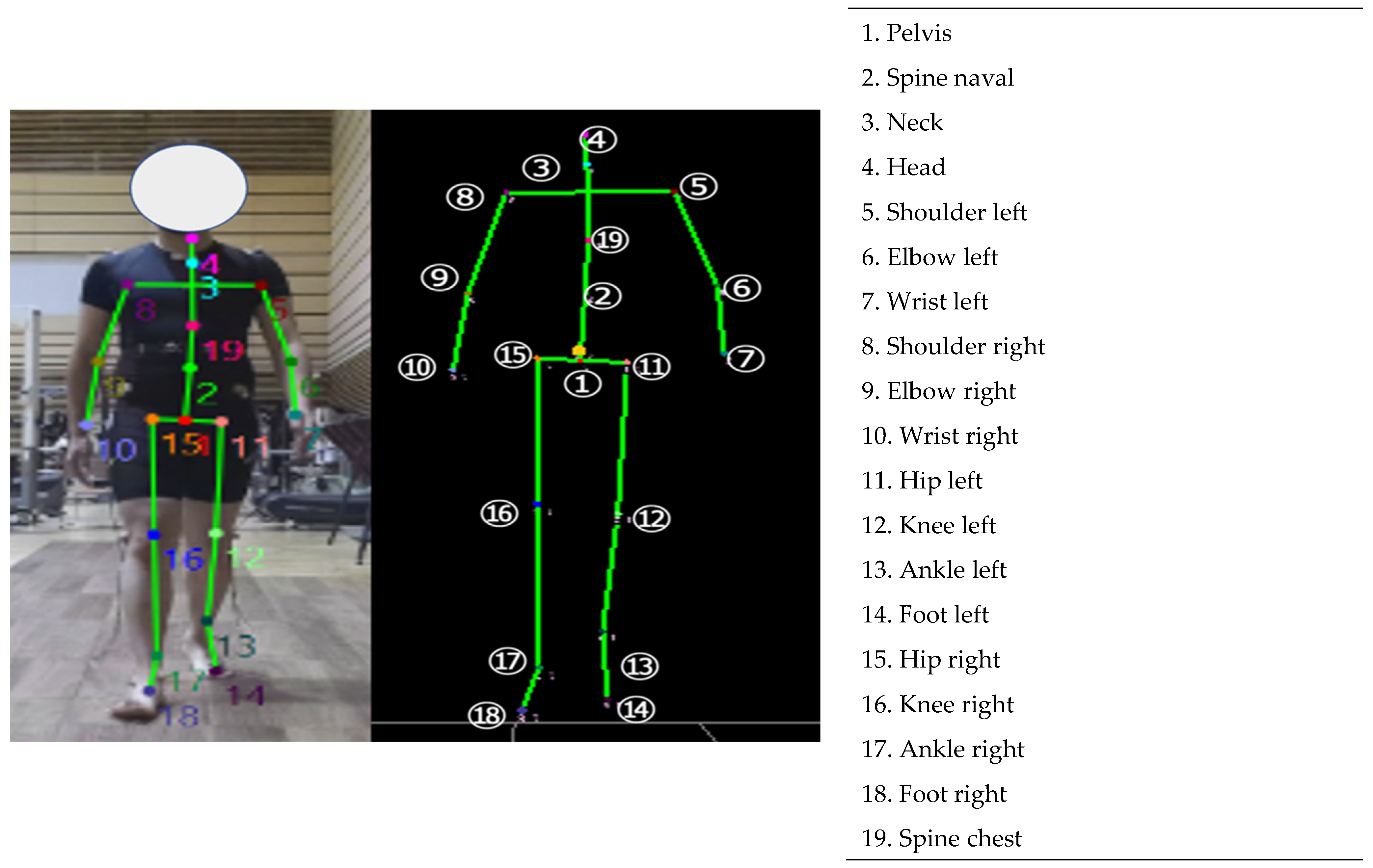
An eight-infrared-camera marker-based 3DMA system (MAC 3D, Motion Analysis Corporation, Santa Rosa, CA, USA) and a depth-sensor-based 3DMA system (Azure Kinect, Microsoft Corporation, Redmond, WA, USA) (ICpro-AK, Hu-tech Co., Ltd., Tama, Tokyo, Japan) were used to simultaneously measure the 3D coordinates of the body landmarks during gait (sampling frequencies of 100 and 30 Hz, respectively). The infrared cameras were placed 3 to 5 m away from the walkway. In this setup, a 500 mm calibration wand could be used for measurement, with a measurement error of <1 mm. The depth sensor was placed 7 m from the starting position of walking, i.e., 1 m behind the endpoint (Figure 1). The depth sensor was positioned in front of the participant, and the height from the floor to the sensor was set at 0.7 m. Prior to the actual experiment, the skeletal recognition of the depth sensor was not displayed when a 19 mm diameter reflective marker was attached to the participant’s body, and the marker- and depth-sensor-based 3DMA systems were used in the measurement. Contrarily, the use of 9.5 mm diameter reflective markers significantly reduced the skeletal recognition error; thus, we used 9.5 mm diameter markers in the actual experiment. Prior to the actual experiments, the 3DMA skeletal recognition using the depth sensor started at a distance of approximately 5 m from the sensor. Given that artifacts were observed immediately after skeletal recognition, the analysis section was set from 1.8 to 3.5 m, similar to that used by Ferraris et al. [24]. A depth sensor, set up according to the instructions for the machine learning-based skeletal recognition technology produced by the Microsoft Corporation, estimated and collected 19 body landmark positions during gait [25] (Figure 2). In the marker-based 3DMA, 19 reflective markers were attached to the body landmarks to calculate the trunk and lower limb kinematics (Figure 3). An experienced physical therapist (K.H.) attached the reflective markers to the body landmarks.

2.4. Failed Trial of Gait Analysis Using Depth-Sensor-Based 3DMA

Of the 32 participants, 10 were unable to walk under the KAFO condition because they could not correctly wear the KAFO, which inhibited them from walking even a single step. Hence, only 22 participants performed the gait trial in the KAFO condition, and 32 participants underwent the gait trial in the slow and very slow conditions. Failed trials (i.e., unsuccessful trials) were observed in 9 (28%), 11 (34%), and 5 (23%) participants in the slow, very slow, and KAFO conditions, respectively. The failed trials were defined as those in which the coordinates of the body landmarks could not be measured by depth-sensor-based 3DMA. After the measurement, the researchers (K.K. and K.H.) exported the coordinate data to determine whether the trial was a failure or not.

2.5. Data Reduction and Analysis

The analysis used three or more successful measurement trials out of five trials in each condition. A successful measurement trial was defined as a successful estimation of the 3D coordinate values of 19 points by the depth-sensor-based 3DMA. MATLAB R2019b (The Math Works, Inc., Natick, MA, USA) was used to calculate the subsequent data analysis process.
The 3D coordinate data measured by the depth sensor were resampled from 30 to 100 Hz using cubic spline interpolation to align the sampling frequencies between pieces of equipment. A zero-lag fourth-order Butterworth low-pass filter (cutoff frequency: 6 Hz) was used to smooth the 3D coordinate data from both pieces of equipment.
The landmarks of the lower limbs (i.e., hip, knee, ankle, and toe) in marker-based 3DMA were defined from the 3D coordinates of the measured reflective markers according to previous studies [26,27,28]. We analyzed the joint angles by projecting the 3D coordinates onto a two-dimensional plane. The trunk flexion–extension and lateral flexion angles in marker- and depth-sensor-based 3DMAs were identified as the angle of the longitudinal axis of the trunk in the sagittal and coronal planes in the global coordinate system. Additionally, the trunk rotation angle was determined as the angle of the mediolateral axis of the trunk in the transversal plane in the global coordinate system. The flexion–extension (dorsiflexion–plantar flexion) angles of the hip, knee, and ankle joints were defined as the angle between the longitudinal axes of the two segments adjacent to the reference joint in the sagittal plane. The leg extension angle was calculated as the angle of the line connecting the hip and ankle joint points in the global coordinate system in the sagittal plane [29].
The center of mass (CoM) was calculated using the 3D coordinate positions of the shanks, thighs, and trunk measured by each piece of equipment and body segment inertia parameters described elsewhere [30]. Foot information was removed from the CoM calculation because toe tracking on the depth sensor is generally very poor [19,31,32]. The CoM velocity was obtained by applying a three-point differential equation to time series data of CoM positions [30].
We analyzed the gait cycle of the right side, from the right initial contact (IC) to the next ipsilateral IC. The IC in the right gait cycle was identified as the point where the right ankle joint point is farthest forward from the pelvic center point [33,34]. The pelvic center point in the marker-based 3DMA was defined as the midpoint between the left and right posterior superior iliac spines. The toe-off (TO) was the point where the right ankle joint point is farthest backward from the pelvic center point [33,34].

2.6. Spatiotemporal Variables

The spatiotemporal variables calculated based on previous reports were as follows [18,19]: step width, right and left step lengths, stride length, cadence, gait velocity, stance phase time, swing phase time, gait cycle time, % stance phase, % swing phase, step length ratio, and swing time ratio.

2.7. Trunk and Lower Limb Kinematics

The mean and peak-to-peak values of the trunk angle in each plane in the trunk kinematics were calculated to determine the upper body sway and average posture during a gait cycle. The maximum (i.e., maximum extension or plantar flexion), minimum (i.e., maximum flexion or dorsiflexion), and peak-to-peak values of each joint angle in the sagittal plane in lower limb kinematics were calculated during a gait cycle. Additionally, the maximum value of the leg extension angle during a gait cycle was calculated as an indicator of propulsion [35].

2.8. Whole-Body Kinematics

The peak-to-peak value of the CoM position in the mediolateral and vertical axes was calculated to determine the whole-body sway during a gait cycle. Additionally, the margin of stability (MoS) was computed as the distance between the extrapolated CoM (XCoM) positions and ankle joint (i.e., boundaries of the base of support) to determine the dynamic stability during gait [36].

2.9. Definition of Abnormal Gait Patterns

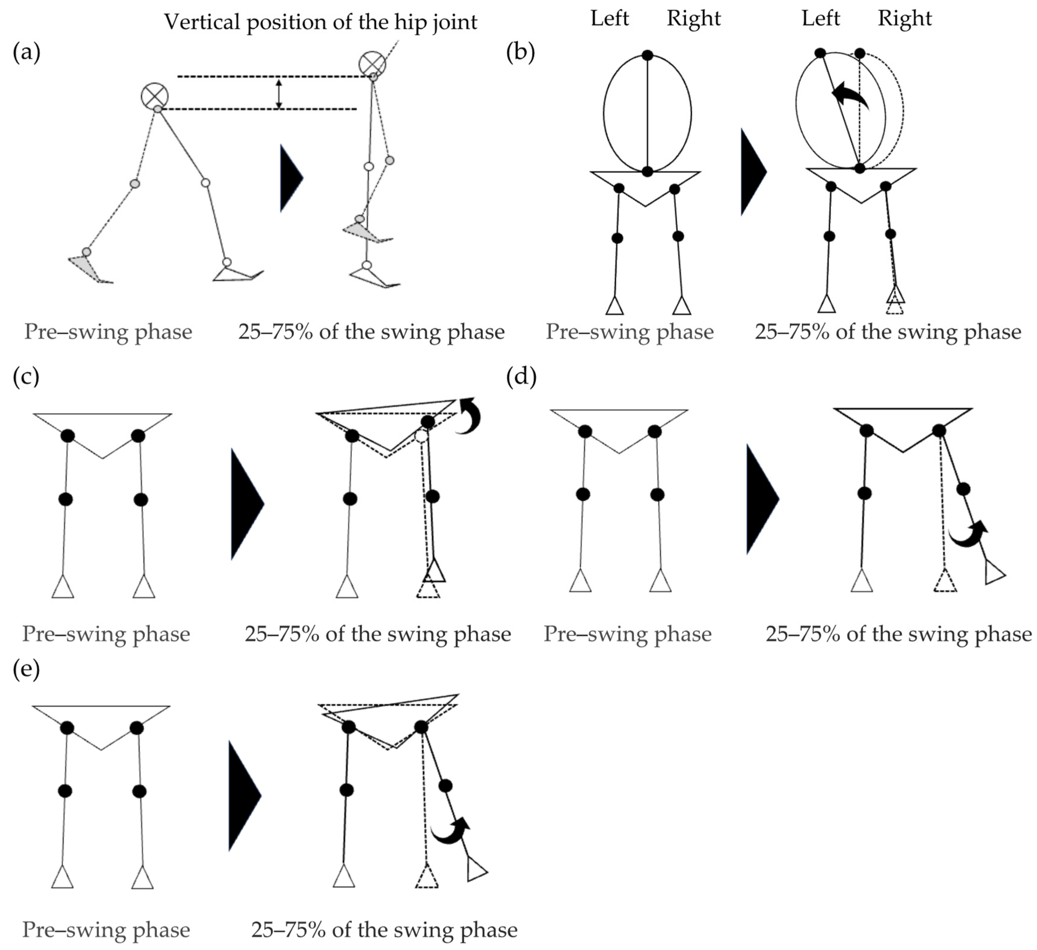
The following five indices were calculated as abnormal gait patterns compensating for toe clearance during the swing phase: contralateral vaulting, trunk lateral flexion to the stance side, hip hiking, swing-side hip abduction, and circumduction. Contralateral vaulting, which is the elevation due to the lower limb on the stance side, was determined by subtracting the maximum height of the stance-side hip during 25–75% of the swing phase by the time-averaged height of the ipsilateral hip during the pre-swing phase (Figure 4a) [37]. The trunk lateral flexion to the stance side was calculated by subtracting the maximum trunk lateral flexion angle during 25–75% of the swing phase by the same time-averaged angle during the pre-swing phase (Figure 4b) [37]. Hip hiking is a pelvic raising movement on the swing limb due to stance-side hip abduction, which was determined by subtracting the maximum pelvic angle (i.e., the line connecting the left–right hip joint) in the coronal plane during 25–75% of the swing phase by the same time-averaged angle during the pre-swing phase (Figure 4c) [11]. The swing-side hip abduction was calculated by subtracting the maximum hip angle (i.e., angle of the thigh relative to the pelvis) in the coronal plane during 25–75% of the swing phase by the same time-averaged angle during the pre-swing phase (Figure 4d) [11,12]. Circumduction is the extent to which the lower extremity deviates from its normal trajectory in the coronal plane as a result of swing-side hip abduction and hip hiking [12], which was calculated by subtracting the maximum thigh angle in the coronal plane (i.e., the angle of the longitudinal axis of the thigh in the coronal plane in the global coordinate system) during 25–75% of the swing phase by the same time-averaged angle during the pre-swing phase (Figure 4e) [12,13,38].

2.10. Statistical Analysis

We initially performed a statistical analysis on a combined sample that integrated all three gait conditions to investigate the concurrent validity of the depth-sensor-based 3DMA in a sample that included individuals with and without compensatory movements for insufficient toe clearance (i.e., a population with high variability). Then, we examined the concurrent validity of the depth-sensor-based 3DMA in a sample of individuals with compensatory movements for insufficient toe clearance (i.e., a population with low variability) by performing statistical analyses for only the KAFO condition. Similarly, statistical analyses were conducted on the samples in each of the slow and very slow conditions (Supplementary Tables S1–S4).
The intraclass correlation coefficient (ICC) is the method for concurrent validation between the two gait analysis systems [19,39]. ICC2,1 is an absolute agreement measure for evaluating the presence of an agreement between the two systems without taking into account the systematic errors, whereas ICC3,1 is a relative agreement measure for evaluating the presence of an agreement between the two systems, taking into account the systematic errors. Therefore, we used ICC2,1 to test whether the depth-sensor- and marker-based 3DMA results are in perfect agreement, and ICC3,1 to test whether the depth-sensor-based 3DMA is an alternative to the marker-based 3DMA when systematic errors are taken into account. The ICC was classified as either poor ( < 0.50), moderate (0.50–0.74), good (0.75–0.90), or excellent ( > 0.90) [39]. The differences between the marker- and depth-sensor-based 3DMA were confirmed by performing paired t-tests. Additionally, the root mean square error (RMSE) between the gait parameters calculated with the marker- and depth-sensor-based 3DMA was identified [40]. IBM Statistical Package for the Social Sciences Statistics (version 26.0, IBM Corporation, Armonk, NY, USA) was used for all statistical analyses. In the present study, we chose “Intraclass correlation coefficient” under [Analyze] > [Scale] > [Reliability Analysis]. For ICC2,1, the model was set to “Two-Way Random” and the type to “Absolute Agreement”; for ICC3,1, these were “Two-Way Mixed” and “Consistency”, respectively.

3. Results

3.1. Walking Speed in Each Condition

The mean and standard deviation of walking speeds were 0.64 ± 0.12, 0.38 ± 0.08, and 0.35 ± 0.07 m/s for the slow, very slow, and KAFO conditions, respectively, in the marker-based 3DMA.

3.2. Concurrent Validity of Abnormal Gait Patterns

In the combined sample, the ICC3,1 of trunk lateral flexion and circumduction showed good validity, ranging from 0.76 to 0.85, whereas that of contralateral vaulting, hip hiking, and swing-side hip abduction showed moderate validity, ranging from 0.57 to 0.64 (Table 3). Conversely, the ICC3,1 of hip hiking in the KAFO condition was 0.38, indicating poor validity. The ICC2,1 results were generally slightly lower than the ICC3,1 results. The measurement errors between instruments were 0.01 m, 1.30°, 1.99°, 2.37°, and 1.53° for contralateral vaulting, trunk lateral flexion, hip hiking, swing-side hip abduction, and circumduction, respectively.

3.3. Concurrent Validity of Spatiotemporal Variables

The ICC2,1 and ICC3,1 for all spatiotemporal variables, except %stance time, %swing time, and step length ratio, ranged from 0.77 to 0.99 in the combined sample, indicating good or excellent validity (Table 4). The other parameters (i.e., %stance time, %swing time, and step length ratio) demonstrated moderate validity (ICC2,1 = 0.58–0.71, ICC3,1 = 0.63–0.71; Table 4).

3.4. Concurrent Validity of Trunk and Lower Limb Kinematics

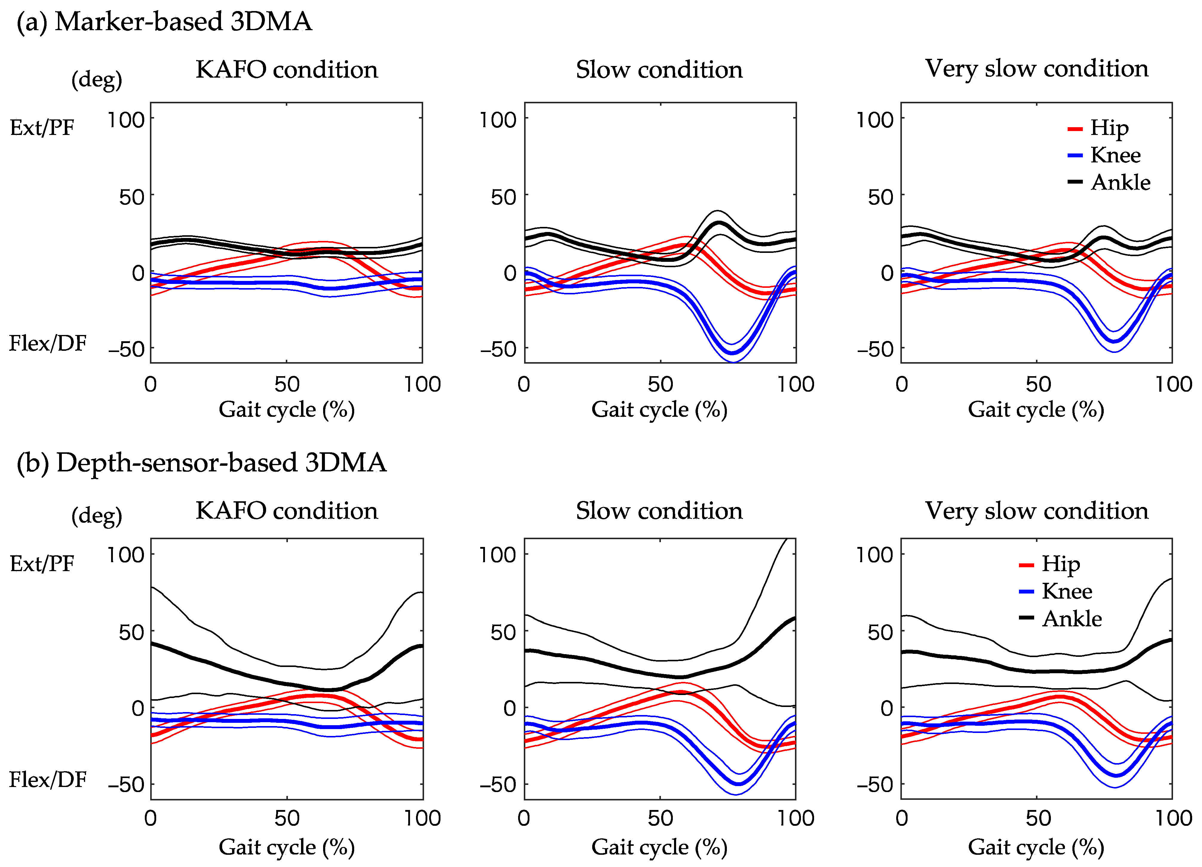
The average hip, knee, and ankle joint angles in the sagittal plane during the gait cycle evaluated by marker-based and depth-sensor-based 3DMA are shown in Figure 5. The ICC3,1 for peak-to-peak angles of the trunk ranged from 0.76 to 0.85 in the combined sample, indicating good validity (Table 5). In the mean angle of the trunk, the ICC3,1 for flexion–extension was good, and that for lateral flexion and rotation was moderate. The ICC3,1 results revealed that the concurrent validity of the hip and knee joint-related parameters and leg extension angle was good or excellent (ICC3,1 = 0.75–0.93), whereas the measure of absolute agreement was varied (ICC2,1 = 0.23–0.93).

3.5. Concurrent Validity of Whole-Body Kinematics

The ICC2,1 and ICC3,1 for the peak-to-peak value of CoM movement in the mediolateral direction ranged from 0.94 to 0.95 in the combined sample, indicating excellent validity (Table 6), whereas the concurrent validity of the peak-to-peak value of CoM movement in the vertical direction was poor. The ICC3,1 of the MoS in the mediolateral and anteroposterior directions was 0.75–0.77, indicating good validity (Table 6).

4. Discussion

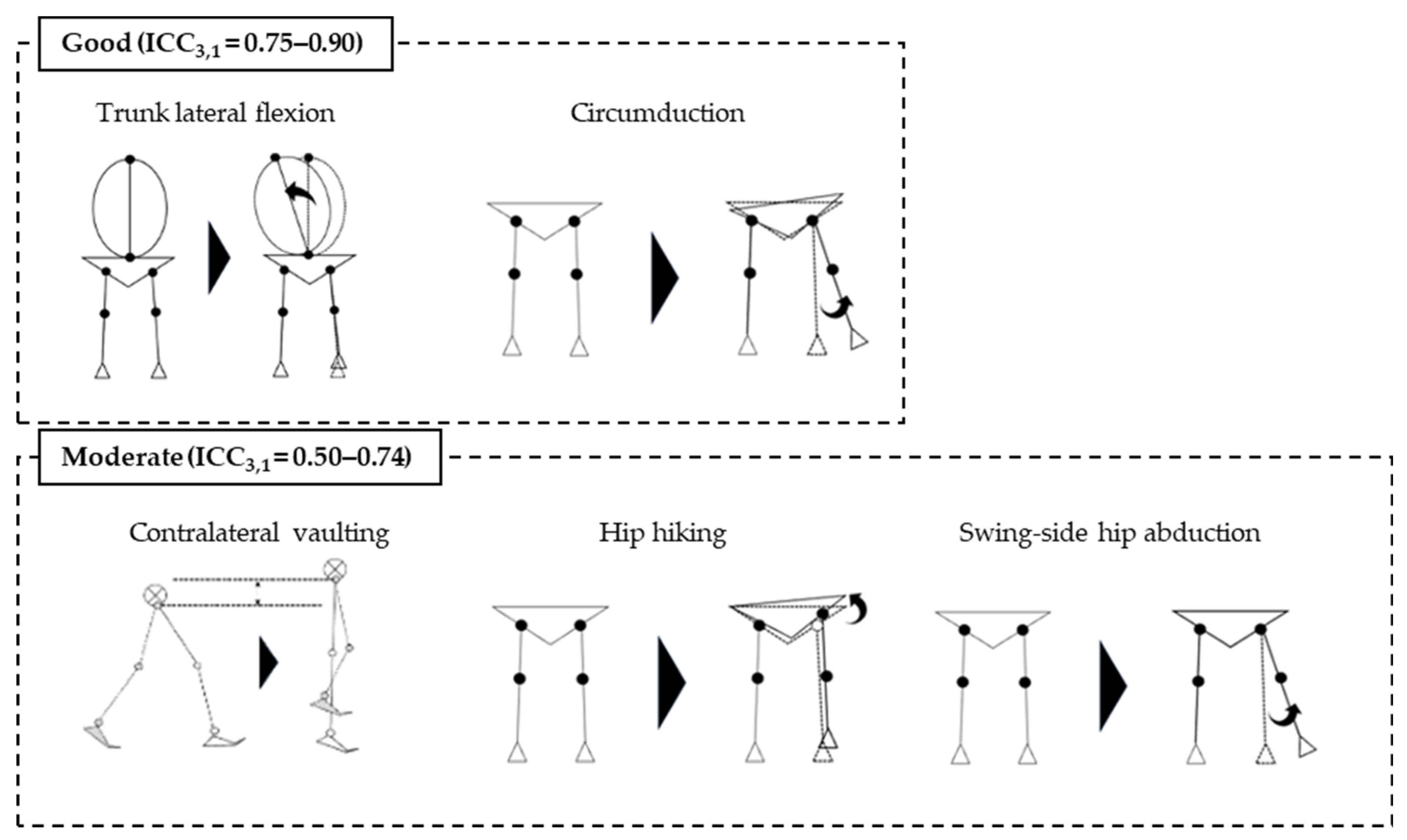
The present study investigated the validity of the quantification of abnormal gait patterns (i.e., compensatory movements due to insufficient toe clearance) by depth-sensor-based 3DMA, as compared to marker-based 3DMA. The results of our study revealed good validity for trunk lateral flexion to the stance side and circumduction and moderate validity for contralateral vaulting, hip hiking, and swing-side hip abduction (Figure 6). The measurement error between instruments ranged from 1.30° to 2.37° and was 0.01 m for contralateral vaulting. Most previous studies have validated depth-sensor-based 3DMA for lower limb joint angles in the sagittal plane, which revealed measurement errors of 4.1–11.3°, 5.3–8.6°, 9.14–38.6°, and 1.11–5.12° for maximum hip flexion, hip extension, knee joint flexion, and knee joint extension angles, respectively, during gait [40,41]. The measurement error of abnormal gait patterns in the coronal plane reported in this study is very small compared to the results of previous studies. This is not a surprising result, because the depth-sensor-based 3DMA estimates the 3D coordinate values of the body landmarks using the contour and depth information of a subject captured from the front. In a previous study investigating the validity of depth-sensor-based 3DMA for estimating hip motion in the coronal plane, a measurement error between devices of 12.5° in hip abduction angle throughout a gait cycle was reported [42]. The present study used Azure Kinect, the successor to Kinect v2 used in the previous study. The smaller measurement error in the abnormal gait pattern measures in the coronal plane in the present study, as compared to that of the previous study, may indicate the higher performance of Azure Kinect’s body landmark estimation. To the best of our knowledge, this is the first study to reveal that depth-sensor-based 3DMA is useful for quantifying compensatory movements due to insufficient toe clearance during the swing phase of gait. However, the circumduction evaluated by depth-sensor-based 3DMA was significantly higher than that by marker-based-3DMA. It must be considered that depth-sensor-based 3DMA estimates body landmarks rather than measuring them; thus, it does not perfectly match the systems that actually measure marker locations.
The ICC3,1 demonstrated good or excellent validity for most of the spatiotemporal and kinematic variables, supporting the results of previous studies [18,19,32,43]. The measurement errors of the angles of the trunk and lower extremity joints, excluding the ankle joint, ranged from 1.08° to 11.0°, which was equal to or less than the results of the aforementioned previous studies [40,41]. Additionally, comparisons between systems showed significantly shorter step lengths, significantly longer %swing phase time, and significantly greater hip and knee flexion for the depth-sensor-based 3DMA than for the marker-based 3DMA. When comparing the results between the marker- and depth-sensor-based 3DMA, we should consider the measurement error. Only the peak-to-peak value of the CoM movement in the vertical direction exhibited poor validity, which is inconsistent with the result of a previous study [24]. Ferraris et al. [24] revealed a highly valid CoM vertical sway, but they defined the CoM position as the midpoint between the left and right hip joints. The CoM is generally calculated from the position and mass of each body segment, and the CoM position described in previous studies was based on a simplified definition. Methodological differences may have caused discrepancies between the results of the previous study and this study. Our study results reveal a greater measurement error of kinematic variables in the sagittal plane than in the coronal plane. Therefore, the peak-to-peak value of the vertical CoM movement may have had less validity because the flexion–extension movement of each joint in the sagittal plane primarily influenced it.
The statistical analysis for the combined sample revealed moderate validity of the assessment for hip hiking using depth-sensor-based 3DMA, but it is important to consider that the greater the variability of the data in the collected sample, the higher the reliability coefficient [44]. Taking this issue into account, the present study conducted a statistical analysis for only the KAFO condition, which demonstrated compensatory movement due to insufficient toe clearance during the swing phase. Hence, the validity of the hip hiking measurement was poor. The hip hiking evaluated by the marker-based 3DMA revealed 11.30° ± 1.90° (mean ± standard deviation) and 3.97° ± 4.87° in the KAFO condition and combined sample, respectively. Therefore, the differences in the standard deviations between conditions may affect the validity results. However, a previous study reported hip hiking of 8.7° ± 4.3° in 23 post-stroke patients [11], which is comparable to the standard deviation of hip hiking in the combined sample of our study. The depth-sensor-based 3DMA may be useful for identifying the compensatory movements during the swing phase, including hip hiking, in post-stroke patients, considering the results of the present study and previous studies, despite the possibility of missing a small difference of approximately 2° of measurement error.
The high validity of depth-sensor-based 3DMA, i.e., markerless 3DMA, for quantifying compensatory movements may accelerate the accumulation of data on gait characteristics in clinical practice. Kinematic and neurological factors reportedly cause compensatory movements, including circumduction and hip hiking, in post-stroke patients [45,46]. Inadequate knee joint flexion during the pre-swing phase of the paretic side is the trigger in the case of kinetic factors, whereas the co-activation of the gluteus medius, which occurs simultaneously with an abnormal stretch reflex in the rectus femoris muscle, is the trigger in the case of neurological factors. As described previously, only a few longitudinal data provide a basis for the effective interventions for compensatory movements during the swing phase in post-stroke patients, despite the partially clarified triggers of compensatory movements among these patients. Accumulating changes in compensatory movements due to insufficient toe clearance before and after a rehabilitation intervention using depth-sensor-based 3DMA may be useful in providing effective gait rehabilitation for post-stroke patients.
The present study has several limitations. First, we defined cases in which body landmark estimation could not be conducted using depth-sensor-based 3DMA as failed trials and excluded them from the data analysis. Prior to the actual experiment, we noticed that the errors in skeletal estimation occur when the reflective markers are large and numerous. Thus, we adjusted the number and size of the markers as described in the Materials and Methods section. Despite this countermeasure, several failed trials still occurred. Unfortunately, our results revealed no reason for the failure. Although we expect the failure rate to decrease in clinical settings where reflective markers are not attached, further investigation is still required to determine the interfering factors, such as the participants’ body types, wear, ambient lighting, and other environmental conditions. Second, the effect of clothing on determining the validity of depth-sensor-based 3DMA was not considered. All of our study participants wore spandex clothing, which may have increased the study’s validity. Restricting clothing is necessary when conducting gait assessment with a depth-sensor-based 3DMA in clinical practice. Third, the effect of the presence or absence of a caregiver on 3D coordinate data by depth-sensor-based 3DMA has not been investigated. This study captured and analyzed only the participants undergoing gait assessment. Placing a caregiver near the patient is often necessary to prevent falls when the depth-sensor-based 3DMA is used in clinical practice. Therefore, investigating the association of the presence of a caregiver with difficulties in measuring 3D coordinate data during gait is essential. Fourth, the present study did not include post-stroke patients. However, depth-sensor-based 3DMA was effective in quantifying compensatory movements during the swing phase, as we examined the validity based on the abnormal gait patterns during the swing phase induced by the KAFO. Finally, this study did not consider simultaneous capture from the sagittal plane. Combining imaging from the sagittal plane may solve the problem of ankle joint motion evaluation, which was very inaccurate in our study.

5. Conclusions

We revealed the high concurrent validity of quantifying compensatory movements due to insufficient toe clearance using a depth-sensor-based 3DMA. The gait assessment using a depth-sensor-based 3DMA can potentially provide a rehabilitation program based on the objective evaluation of gait in clinical practice.

Supplementary Materials

The following supporting information can be downloaded at https://www.mdpi.com/article/10.3390/biomechanics4030028/s1: Table S1: The concurrent validity of the abnormal gait patterns in the slow and very slow conditions, Table S2: The concurrent validity of the spatiotemporal variables in the slow and very slow conditions, Table S3: The concurrent validity of the trunk and lower limb kinematics in the slow and very slow conditions, Table S4: The concurrent validity of the whole-body kinematics in the slow and very slow conditions.

Author Contributions

Conceptualization, K.K., S.M., D.N., M.K., H.H., T.M. (Toshihiro Miwa), T.M. (Toru Maeda), T.N., S.N. and K.H.; Data curation, K.K., D.N., T.M. (Toshihiro Miwa), and K.H.; Formal analysis, K.K. and K.H.; Funding acquisition, K.H.; Investigation, K.K. and K.H.; Methodology, K.K., S.M., D.N., M.K., H.H., T.M. (Toshihiro Miwa), T.M. (Toru Maeda), T.N., S.N. and K.H.; Project administration, K.K. and K.H.; Resources, K.H.; Software, K.K. and K.H.; Supervision, S.N. and K.H.; Validation, K.K. and K.H.; Visualization, K.K. and K.H.; Writing—original draft, K.K. and K.H.; Writing—review and editing, K.K., S.M., D.N., M.K., H.H., T.M. (Toshihiro Miwa), T.M. (Toru Maeda), T.N., S.N. and K.H. All authors have read and agreed to the published version of the manuscript.

Funding

This work was supported by JSPS KAKENHI [Grant Number 22K11443].

Institutional Review Board Statement

The study was conducted in accordance with the guidelines stipulated in the Declaration of Helsinki and approved by the Ethics Committee of Kumamoto Health Science University (protocol code: 22043; date of approval: 7 February 2023).

Informed Consent Statement

Informed consent was obtained from all participants involved in the study. Written informed consent was obtained from the participants to publish this paper.

Data Availability Statement

Data are available on request due to privacy and ethical restrictions.

Acknowledgments

We would like to thank TOKUDA Prosthetics and Orthotics Mfg Ltd. for lending us the Modular Leg Brace NEO.

Conflicts of Interest

The authors have received KAFO (Modular Leg Brace NEO) on loan from TOKUDA Prosthetics and Orthotics Mfg Ltd.

References

  1. Van de Port, I.G.; Kwakkel, G.; Lindeman, E. Community ambulation in patients with chronic stroke: How is it related to gait speed? J. Rehabil. Med. 2008, 40, 23–27. [Google Scholar] [CrossRef] [PubMed]
  2. Thilarajah, S.; Mentiplay, B.F.; Bower, K.J.; Tan, D.; Pua, Y.H.; Williams, G.; Koh, G.; Clark, R.A. Factors associated with post-stroke physical activity: A systematic review and meta-analysis. Arch. Phys. Med. Rehabil. 2018, 99, 1876–1889. [Google Scholar] [CrossRef] [PubMed]
  3. Weerdesteyn, V.; de Niet, M.; van Duijnhoven, H.J.; Geurts, A.C. Falls in individuals with stroke. J. Rehabil. Res. Dev. 2008, 45, 1195–1213. [Google Scholar] [CrossRef] [PubMed]
  4. Michael, K.M.; Allen, J.K.; Macko, R.F. Reduced ambulatory activity after stroke: The role of balance, gait, and cardiovascular fitness. Arch. Phys. Med. Rehabil. 2005, 86, 1552–1556. [Google Scholar] [CrossRef] [PubMed]
  5. Perry, J.; Garrett, M.; Gronley, J.K.; Mulroy, S.J. Classification of walking handicap in the stroke population. Stroke 1995, 26, 982–989. [Google Scholar] [CrossRef] [PubMed]
  6. Fulk, G.D.; He, Y.; Boyne, P.; Dunning, K. Predicting home and community walking activity poststroke. Stroke 2017, 48, 406–411. [Google Scholar] [CrossRef] [PubMed]
  7. Hsiao, H.; Awad, L.N.; Palmer, J.A.; Higginson, J.S.; Binder-Macleod, S.A. Contribution of paretic and nonparetic limb peak propulsive forces to changes in walking speed in individuals poststroke. Neurorehabil. Neural Repair 2016, 30, 743–752. [Google Scholar] [CrossRef] [PubMed]
  8. Patterson, K.K.; Mansfield, A.; Biasin, L.; Brunton, K.; Inness, E.L.; McIlroy, W.E. Longitudinal changes in poststroke spatiotemporal gait asymmetry over inpatient rehabilitation. Neurorehabil. Neural Repair 2015, 29, 153–162. [Google Scholar] [CrossRef] [PubMed]
  9. Awad, L.N.; Palmer, J.A.; Pohlig, R.T.; Binder-Macleod, S.A.; Reisman, D.S. Walking speed and step length asymmetry modify the energy cost of walking after stroke. Neurorehabil. Neural Repair 2015, 29, 416–423. [Google Scholar] [CrossRef]
  10. Jørgensen, L.; Crabtree, N.J.; Reeve, J.; Jacobsen, B.K. Ambulatory level and asymmetrical weight bearing after stroke affects bone loss in the upper and lower part of the femoral neck differently: Bone adaptation after decreased mechanical loading. Bone 2000, 27, 701–707. [Google Scholar] [CrossRef]
  11. Kerrigan, D.C.; Frates, E.P.; Rogan, S.; Riley, P.O. Hip hiking and circumduction: Quantitative definitions. Am. J. Phys. Med. Rehabil. 2000, 79, 247–252. [Google Scholar] [CrossRef]
  12. Stanhope, V.A.; Knarr, B.A.; Reisman, D.S.; Higginson, J.S. Frontal plane compensatory strategies associated with self-selected walking speed in individuals post-stroke. Clin. Biomech. 2014, 29, 518–522. [Google Scholar] [CrossRef]
  13. Tyrell, C.M.; Roos, M.A.; Rudolph, K.S.; Reisman, D.S. Influence of systematic increases in treadmill walking speed on gait kinematics after stroke. Phys. Ther. 2011, 91, 392–403. [Google Scholar] [CrossRef] [PubMed]
  14. Mukaino, M.; Ohtsuka, K.; Tanikawa, H.; Matsuda, F.; Yamada, J.; Itoh, N.; Saitoh, E. Clinical-oriented three-dimensional gait analysis method for evaluating gait disorder. J. Vis. Exp. 2018, 133, e57063. [Google Scholar] [CrossRef]
  15. Clark, R.A.; Vernon, S.; Mentiplay, B.F.; Miller, K.J.; McGinley, J.L.; Pua, Y.H.; Paterson, K.; Bower, K.J. Instrumenting gait assessment using the Kinect in people living with stroke: Reliability and association with balance tests. J. Neuroeng. Rehabil. 2015, 12, 15. [Google Scholar] [CrossRef] [PubMed]
  16. Latorre, J.; Colomer, C.; Alcañiz, M.; Llorens, R. Gait analysis with the Kinect v2: Normative study with healthy individuals and comprehensive study of its sensitivity, validity, and reliability in individuals with stroke. J. Neuroeng. Rehabil. 2019, 16, 97. [Google Scholar] [CrossRef]
  17. Lachat, E.; Macher, H.; Landes, T.; Grussenmeyer, P. Assessment and calibration of a RGB-D camera (Kinect v2 Sensor) towards a potential use for close-range 3D modeling. Remote Sens. 2015, 7, 13070–13097. [Google Scholar] [CrossRef]
  18. Usami, T.; Nishida, K.; Iguchi, H.; Okumura, T.; Sakai, H.; Ida, R.; Horiba, M.; Kashima, S.; Sahashi, K.; Asai, H.; et al. Evaluation of lower extremity gait analysis using Kinect V2® tracking system. SICOT J. 2022, 8, 27. [Google Scholar] [CrossRef]
  19. Eltoukhy, M.; Oh, J.; Kuenze, C.; Signorile, J. Improved kinect-based spatiotemporal and kinematic treadmill gait assessment. Gait Posture 2017, 51, 77–83. [Google Scholar] [CrossRef]
  20. Matsuda, F.; Mukaino, M.; Ohtsuka, K.; Tanikawa, H.; Tsuchiyama, K.; Teranishi, T.; Kanada, Y.; Kagaya, H.; Saitoh, E. Biomechanical factors behind toe clearance during the swing phase in hemiparetic patients. Top. Stroke Rehabil. 2017, 24, 177–182. [Google Scholar] [CrossRef]
  21. Zissimopoulos, A.; Fatone, S.; Gard, S.A. Biomechanical and energetic effects of a stance-control orthotic knee joint. J. Rehabil. Res. Dev. 2007, 44, 503–513. [Google Scholar] [CrossRef] [PubMed]
  22. Akbas, T.; Prajapati, S.; Ziemnicki, D.; Tamma, P.; Gross, S.; Sulzer, J. Hip circumduction is not a compensation for reduced knee flexion angle during gait. J. Biomech. 2019, 87, 150–156. [Google Scholar] [CrossRef] [PubMed]
  23. Wang, Y.; Mukaino, M.; Ohtsuka, K.; Otaka, Y.; Tanikawa, H.; Matsuda, F.; Tsuchiyama, K.; Yamada, J.; Saitoh, E. Gait characteristics of post-stroke hemiparetic patients with different walking speeds. Int. J. Rehabil. Res. 2020, 43, 69–75. [Google Scholar] [CrossRef]
  24. Ferraris, C.; Cimolin, V.; Vismara, L.; Votta, V.; Amprimo, G.; Cremascoli, R.; Galli, M.; Nerino, R.; Mauro, A.; Priano, L. Monitoring of gait parameters in post-stroke individuals: A feasibility study using RGB-D sensors. Sensors 2021, 21, 5945. [Google Scholar] [CrossRef] [PubMed]
  25. Learn Microsoft. Available online: https://learn.microsoft.com/ja-jp/azure/kinect-dk/body-joints (accessed on 14 May 2024).
  26. Kurabayashi, J.; Mochimaru, M.; Kouchi, M. Validation of the estimation methods for the hip joint center. J. Soc. Biomech. 2003, 27, 28–36. [Google Scholar] [CrossRef]
  27. Tokuda, K.; Anan, M.; Takahashi, M.; Sawada, T.; Tanimoto, K.; Kito, N.; Shinkoda, K. Biomechanical mechanism of lateral trunk lean gait for knee osteoarthritis patients. J. Biomech. 2018, 66, 10–17. [Google Scholar] [CrossRef]
  28. Kagami, S.; Mochimaru, M.; Ehara, Y.; Miyata, N.; Nishiwaki, K.; Kanade, T.; Inoue, H. Measurement and comparison of humanoid H7 walking with human being. Robot. Auton. Syst. 2004, 48, 177–187. [Google Scholar] [CrossRef]
  29. Mizuta, N.; Hasui, N.; Kai, T.; Inui, Y.; Sato, M.; Ohnishi, S.; Taguchi, J.; Nakatani, T. Characteristics of limb kinematics in the gait disorders of post-stroke patients. Sci. Rep. 2024, 14, 3082. [Google Scholar] [CrossRef] [PubMed]
  30. Winter, D.A.; Quanbury, A.O.; Hobson, D.A.; Sidwall, H.G.; Reimer, G.; Trenholm, B.G.; Steinke, T.; Shlosser, H. Kinematics of normal locomotion—A statistical study based on T.V. data. J. Biomech. 1974, 7, 479–486. [Google Scholar] [CrossRef]
  31. Clark, R.A.; Bower, K.J.; Mentiplay, B.F.; Paterson, K.; Pua, Y.H. Concurrent validity of the Microsoft Kinect for assessment of spatiotemporal gait variables. J. Biomech. 2013, 46, 2722–2725. [Google Scholar] [CrossRef]
  32. Mentiplay, B.F.; Perraton, L.G.; Bower, K.J.; Pua, Y.H.; McGaw, R.; Heywood, S.; Clark, R.A. Gait assessment using the Microsoft Xbox One Kinect: Concurrent validity and inter-day reliability of spatiotemporal and kinematic variables. J. Biomech. 2015, 48, 2166–2170. [Google Scholar] [CrossRef] [PubMed]
  33. French, M.A.; Koller, C.; Arch, E.S. Comparison of three kinematic gait event detection methods during overground and treadmill walking for individuals post stroke. J. Biomech. 2020, 99, 109481. [Google Scholar] [CrossRef] [PubMed]
  34. Zeni, J.A., Jr.; Richards, J.G.; Higginson, J.S. Two simple methods for determining gait events during treadmill and overground walking using kinematic data. Gait Posture 2008, 27, 710–714. [Google Scholar] [CrossRef] [PubMed]
  35. Matsuzawa, Y.; Miyazaki, T.; Takeshita, Y.; Higashi, N.; Hayashi, H.; Araki, S.; Nakatsuji, S.; Fukunaga, S.; Kawada, M.; Kiyama, R. Effect of leg extension angle on knee flexion angle during swing phase in post-stroke gait. Medicina 2021, 57, 1222. [Google Scholar] [CrossRef] [PubMed]
  36. Hof, A.L.; Gazendam, M.G.; Sinke, W.E. The condition for dynamic stability. J. Biomech. 2005, 38, 1–8. [Google Scholar] [CrossRef] [PubMed]
  37. Tanikawa, H.; Ohtsuka, K.; Mukaino, M.; Inagaki, K.; Matsuda, F.; Teranishi, T.; Kanada, Y.; Kagaya, H.; Saitoh, E. Quantitative assessment of retropulsion of the hip, excessive hip external rotation, and excessive lateral shift of the trunk over the unaffected side in hemiplegia using three-dimensional treadmill gait analysis. Top. Stroke Rehabil. 2016, 23, 311–317. [Google Scholar] [CrossRef]
  38. Itoh, N.; Kagaya, H.; Saitoh, E.; Ohtsuka, K.; Yamada, J.; Tanikawa, H.; Tanabe, S.; Itoh, N.; Aoki, T.; Kanada, Y. Quantitative assessment of circumduction, hip hiking, and forefoot contact gait using lissajous figures. Jpn. J. Compr. Rehabil. Sci. 2012, 3, 78–84. [Google Scholar] [CrossRef]
  39. Koo, T.K.; Li, M.Y. A Guideline of Selecting and Reporting Intraclass Correlation Coefficients for Reliability Research. J. Chiropr. Med. 2016, 15, 155–163. [Google Scholar] [CrossRef] [PubMed]
  40. Pfister, A.; West, A.M.; Bronner, S.; Noah, J.A. Comparative abilities of Microsoft Kinect and Vicon 3D motion capture for gait analysis. J. Med. Eng. Technol. 2014, 38, 274–280. [Google Scholar] [CrossRef]
  41. Xu, X.; McGorry, R.W.; Chou, L.S.; Lin, J.H.; Chang, C.C. Accuracy of the Microsoft Kinect for measuring gait parameters during treadmill walking. Gait Posture 2015, 42, 145–151. [Google Scholar] [CrossRef]
  42. Ma, Y.; Mithraratne, K.; Wilson, N.C.; Wang, X.; Ma, Y.; Zhang, Y. The validity and reliability of a kinect v2-based gait analysis system for children with cerebral palsy. Sensors 2019, 19, 1660. [Google Scholar] [CrossRef]
  43. Tamura, H.; Tanaka, R.; Kawanishi, H. Reliability of a markerless motion capture system to measure the trunk, hip and knee angle during walking on a flatland and a treadmill. J. Biomech. 2020, 109, 109929. [Google Scholar] [CrossRef]
  44. Stratford, P.W.; Goldsmith, C.H. Use of the standard error as a reliability index of interest: An applied example using elbow flexor strength data. Phys. Ther. 1997, 77, 745–750. [Google Scholar] [CrossRef] [PubMed]
  45. Akbas, T.; Neptune, R.R.; Sulzer, J. Neuromusculoskeletal simulation reveals abnormal rectus femoris-gluteus medius coupling in post-stroke gait. Front. Neurol. 2019, 10, 301. [Google Scholar] [CrossRef] [PubMed]
  46. Hall, A.L.; Peterson, C.L.; Kautz, S.A.; Neptune, R.R. Relationships between muscle contributions to walking subtasks and functional walking status in persons with post-stroke hemiparesis. Clin. Biomech. 2011, 26, 509–515. [Google Scholar] [CrossRef] [PubMed]
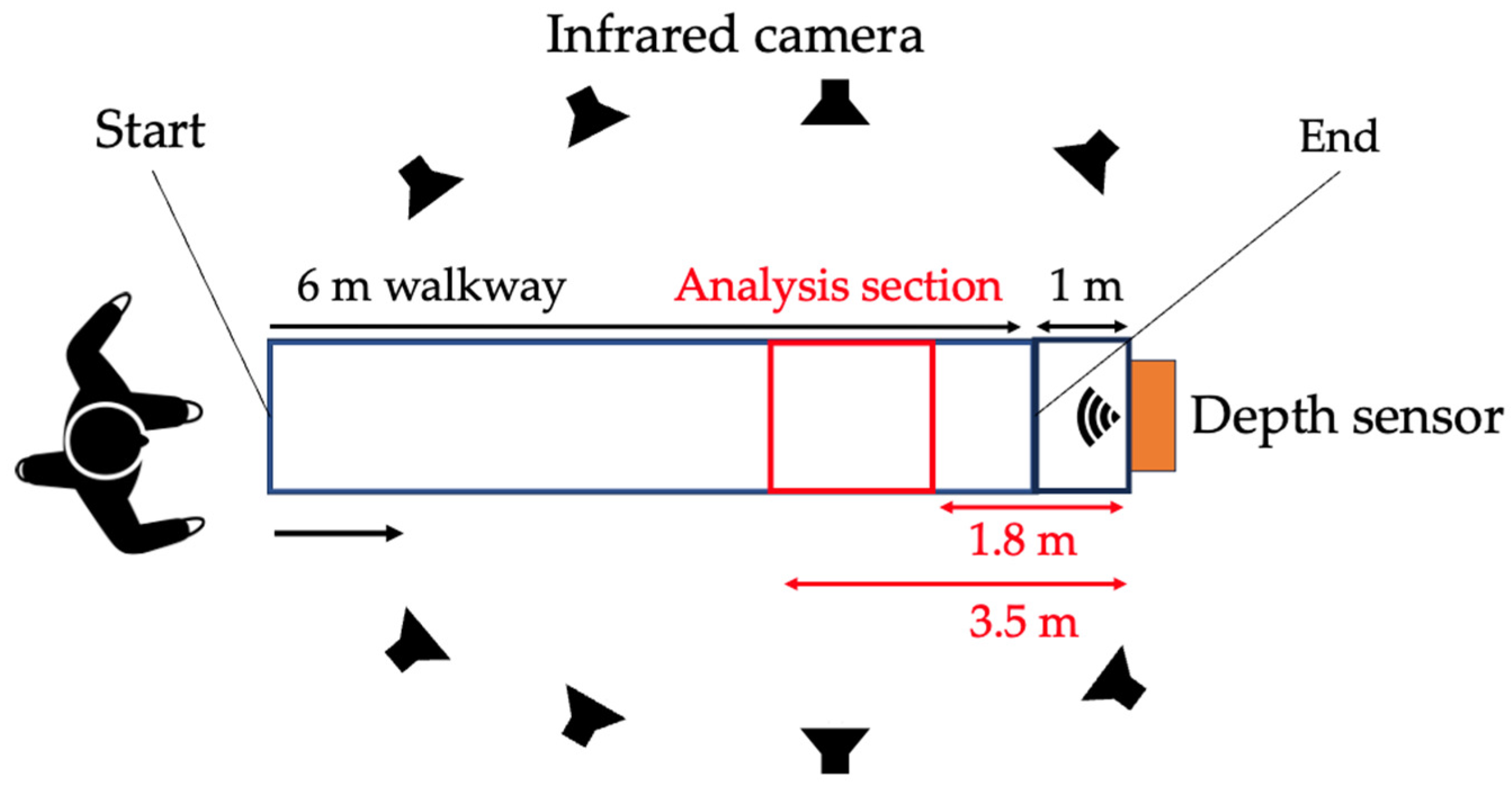
Figure 1. Overview of the experimental setup.
Biomechanics 04 00028 g001
Figure 2. Body landmarks derived from the skeletal recognition technology of Azure Kinect.
Biomechanics 04 00028 g002
Figure 3. Marker locations for marker-based 3D motion analysis.
Biomechanics 04 00028 g003
Figure 4. Definition of abnormal gait patterns: contralateral vaulting (a), trunk lateral flexion to the stance side (b), hip hiking (c), swing-side hip abduction (d), and circumduction (e).
Biomechanics 04 00028 g004
Figure 5. Average (thick line) and 1 SD (fine line) of hip and knee extension and ankle plantar flexion angles during gait cycle for each condition as evaluated with marker-based (a) and depth-sensor-based 3DMA (b) systems.
Biomechanics 04 00028 g005
Figure 6. Summary for the concurrent validity of abnormal gait patterns.
Biomechanics 04 00028 g006
Table 1. Methods for assessing compensatory movements during the swing phase.
StudyParticipantsIndicators of Compensatory Movements during Swing PhaseEquipment
Kerrigan et al. [11]Post-stroke patients (n = 23), healthy people
(n = 23)
Peak values during paretic swing phase (coronal pelvic angle, transverse pelvic rotation, hip adduction, hip abduction, thigh adduction, and thigh abduction), values at mid-swing (coronal pelvic angle, transverse pelvic angle, bilateral coronal hip angle, and affected thigh angle)Marker-based 3DMA
Stanhope et al. [12]Post-stroke patients (n = 21)Peak paretic pelvic tilt angle, peak paretic hip abduction angle, toe displacementMarker-based 3DMA
Tyrell et al. [13]Post-stroke patients (n = 22)Hip hiking (the angle in the frontal plane between the pelvis position in static standing and the maximum deviation from that position in the swing phase), circumduction (maximum lateral difference between the position of the heel marker in the stance phase and the same heel marker position in the swing phase immediately following the stance phase)Marker-based 3DMA
Table 2. Participant information.
Sex (male, female) a32 (19/13)
Age (years) b 20.4   ±   2.0
Height (cm) b 164.4   ±   9.8
Weight (kg) b 60.0   ±   9.3
a Number of participants; b mean ± standard deviation.
Table 3. Concurrent validity of abnormal gait pattern.
VariablesMarker-Based 3DMADepth-Sensor-Based 3DMAp-ValueICC2,1 (95% CI)ICC3,1 (95% CI)RMSE
Combined sample
Contralateral vaulting (m) 0.01   ±   0.01 0.01   ±   0.010.8270.57 (0.37–0.72)0.57 (0.37–0.71)0.01
Trunk lateral flexion to stance side (deg) 3.39   ±   2.42 2.59   ±   2.060.6240.80 (0.55–0.90)0.85 (0.77–0.90)1.30
Hip hiking (deg) 3.97   ±   4.87 2.91   ±   2.450.1030.59 (0.39–0.72)0.64 (0.47–0.77)1.99
Swing-side hip abduction (deg) 2.47   ±   3.13 2.68   ±   1.920.4980.59 (0.40–0.73)0.59 (0.40–0.73)2.37
Circumduction (deg) 4.01   ±   2.68 8.46   ±   2.57 < 0.001 a0.61 (0.26–0.78)0.76 (0.63–0.84)1.53
KAFO condition
Contralateral vaulting (m) 0.01   ±   0.01 0.01   ±   0.010.6440.51 (0.08–0.79)0.56 (0.12–0.82)0.01
Trunk lateral flexion to stance side (deg) 6.23   ±   2.31 4.82   ±   1.95 < 0.001 a0.66 (0.04–0.89)0.79 (0.51–0.92)1.43
Hip hiking (deg) 11.33   ±   1.90 5.80   ±   2.250.047 a 0.37   ( 0.09–0.75) 0.38   ( 0.11–0.72)1.77
Swing-side hip abduction (deg) 1.09   ±   1.90 1.31   ±   2.170.083 0.51   ( 0.09–0.84)0.83 (0.60–0.94)2.67
Circumduction (deg) 6.82   ±   2.77 10.43   ±   3.290.016 a 0.65   ( 0.03–0.89)0.72 (0.38–0.89)0.96
Mean ± standard deviation; 3DMA: three-dimensional motion analysis; ICC: intraclass correlation coefficient; RMSE: root mean square error; KAFO: knee–ankle–foot orthosis; a significant difference between systems (p  < 0.05).
Table 4. Concurrent validity of spatiotemporal variables.
VariablesMarker-Based 3DMADepth-Sensor-Based 3DMAp-ValueICC2,1 (95% CI)ICC3,1 (95% CI)RMSE
Combined sample
Step width (m) 0.18   ±   0.04 0.18   ±   0.040.2130.89 (0.79–0.91)0.87 (0.78–0.91)0.02
Step length (m)Right 0.34   ±   0.08 0.31   ±   0.08 < 0.001 a0.93 (0.51–0.98)0.96 (0.95–0.98)0.03
Left 0.34   ±   0.08 0.32   ±   0.08 < 0.001 a0.93 (0.56–0.97)0.96 (0.94–0.98)0.03
Stride length (m) 0.75   ±   0.19 0.77   ±   0.19 < 0.001 a0.98 (0.96–0.99)0.98 (0.98–0.99)0.04
Cadence (steps/min) 78.17   ±   9.93 78.62   ±   10.200.1460.97 (0.95–0.98)0.97 (0.95–0.98)2.40
Gait velocity (m/s) 0.47   ±   0.17 0.47   ±   0.170.013 a0.99 (0.99–1.00)0.99 (0.99–1.00)0.01
Stance time (s) 1.03   ±   0.15 1.01   ±   0.150.2220.93 (0.88–0.96)0.94 (0.90–0.96)0.05
Swing time (s) 0.52   ±   0.05 0.53   ±   0.050.4770.80 (0.67–0.88)0.82 (0.73–0.83)0.03
Gait cycle time (s) 1.55   ±   0.19 1.54   ±   0.190.2170.97 (0.96–0.98)0.97 (0.95–0.98)0.04
% Stance   time   (%) 66.5   ±   2.44 65.5   ±   2.33 < 0.001 a0.58 (0.34–0.74)0.63 (0.45–0.76)2.27
% Swing   time   (%) 33.5   ±   2.46 34.5   ±   2.37 < 0.001 a0.58 (0.34–0.74)0.63 (0.43–0.76)2.27
Step length ratio 0.99   ±   0.12 0.99   ±   0.150.7050.71 (0.56–0.82)0.71 (0.55–0.81)0.10
Swing time ratio 1.06   ±   0.09 1.02   ±   0.100.021 a0.71 (0.42–0.85)0.77 (0.65–0.86)0.08
KAFO condition
Step width (m) 0.22   ±   0.03 0.22   ±   0.050.0870.87(0.67–0.95)0.88 (0.71–0.96)0.02
Step length (m)Right 0.28   ±   0.07 0.25   ±   0.06 < 0.001 a0.85 (0.17–0.96)0.93 (0.81–0.97)0.04
Left 0.29   ±   0.06 0.28   ±   0.05 < 0.001 a0.93 (0.80–0.97)0.94 (0.84–0.98)0.03
Stride length (m) 0.62   ±   0.13 0.63   ±   0.110.1210.97 (0.92–0.99)0.97 (0.92–0.99)0.03
Cadence (steps/min) 70.12   ±   1.54 71.03   ±   2.380.124 0.35   ( 0.09–0.70) 0.74   ( 0.11–0.72)2.42
Gait velocity (m/s) 0.35   ±   0.07 0.35   ±   0.060.0630.94 (0.90–0.99)0.97 (0.92–0.99)0.02
Stance time (s) 1.14   ±   0.05 1.13   ±   0.060.251 0.36   ( 0.10–0.71) 0.37   ( 0.12–0.71)0.06
Swing time (s) 0.57   ±   0.05 0.57   ±   0.040.9300.72 (0.38–0.89)0.72 (0.37–0.86)0.04
Gait cycle time (s) 1.71   ±   0.04 1.70   ±   0.050.180 0.35   ( 0.11–0.70) 0.36   ( 0.13–0.71)0.04
% Stance   time   (%) 66.7   ±   2.60 66.3   ±   2.400.5180.63 (0.22–0.84)0.62 (0.21–0.84)2.26
% Swing   time   (%) 33.3   ±   2.60 33.7   ±   2.400.5180.63 (0.22–0.85)0.62 (0.21–0.84)2.26
Step length ratio 0.97   ±   0.15 0.91   ±   0.160.027 a0.75 (0.38–0.91)0.79 (0.52–0.92)0.12
Swing time ratio 1.16   ±   0.11 1.12   ±   0.110.0610.66 (0.28–0.86)0.69 (0.35–0.88)0.10
Mean ± standard deviation; 3DMA: three-dimensional motion analysis; ICC: intraclass correlation coefficients; RMSE: root mean square error; KAFO: knee–ankle–foot orthosis; a significant difference between systems (p  < 0.05).
Table 5. Concurrent validity of the trunk and lower limb kinematics.
VariablesMarker-Based 3DMADepth-Sensor-Based 3DMAp-ValueICC2,1 (95% CI)ICC3,1 (95% CI)RMSE
Combined sample
Trunk angle (deg)
Peak-to-peak
Flexion–extension 3.78   ±   1.77 4.73   ±   1.85 < 0.001 a0.74 (0.22–0.90)0.85 (0.75–0.90)1.49
Lateral flexion 5.89   ±   3.37 5.96   ±   2.130.0990.76 (0.63–0.86)0.76 (0.63–0.84)1.89
Rotation 10.82   ±   3.45 13.62   ±   4.30 < 0.001 a0.79 (0.01–0.85)0.79 (0.68–0.87)3.77
Mean
Flexion–extension 3.20   ±   3.20 2.70   ±   2.430.086 0.27   ( 0.03–0.65)0.85 (0.76–0.91)6.10
Lateral flexion 0.71   ±   1.41 0.28   ±   1.06 < 0.001 a0.65 (0.44–0.77)0.69 (0.53–0.80)1.08
Rotation 0.61   ±   3.87 0.90   ±   3.170.3860.73 (0.58–0.83)0.72 (0.58–0.83)2.63
Hip joint angle [+extension/−flexion] (deg)
Maximum 15.89   ±   4.81 9.23   ±   4.63 < 0.001 a0.40 (0.07–0.75)0.80 (0.69–0.87)7.42
Minimum 13.17   ±   4.94 23.76   ±   4.46 < 0.001 a0.23 (0.03–0.60)0.80 (0.70–0.88)11.00
Peak-to-peak 29.05   ±   5.33 32.99   ±   6.230.0920.72 (0.06–0.93)0.93 (0.89–0.96)4.45
Knee joint angle [+extension/−flexion] (deg)
Maximum 1.33   ±   4.18 6.70   ±   2.75 < 0.001 a 0.62   ( 0.07–0.86)0.75 (0.69–0.80)6.24
Minimum 40.04   ±   18.63 39.86   ±   15.900.5220.93 (0.83–0.95)0.92 (0.88–0.95)5.93
Peak-to-peak 38.71   ±   20.53 33.90   ±   15.10 < 0.001 a0.87 (0.70–0.93)0.90 (0.84–0.94)8.52
Ankle joint angle [+plantar flexion/−dorsal flexion] (deg)
Maximum 28.05   ±   7.09 64.09   ±   33.10 < 0.001 a0.03 (–0.12–0.15)0.05 (–0.30–0.20)49.67
Minimum 6.61   ±   3.87 10.80   ±   8.56 < 0.001 a0.05(–0.12–0.10)0.27 (–0.49–0.03)10.81
Peak-to-peak 21.44   ±   8.06 53.29   ±   36.56 < 0.001 a0.43 (0.02–0.67)0.57 (–0.37–0.71)49.63
Maximum leg extension angle (deg) 19.82   ±   3.89 17.75   ±   3.74 < 0.001 a0.81 (0.03–0.93)0.92 (0.87–0.95)2.56
KAFO condition
Trunk angle (deg)
Peak-to-peak
Flexion–extension 5.86   ±   1.94 7.00   ±   1.48 < 0.001 a0.71 (0.03–0.91)0.85 (0.64–0.94)1.47
Lateral flexion 10.31   ±   2.50 8.42   ±   1.65 < 0.001 a 0.57   ( 0.07–0.81)0.69 (0.32–0.87)1.89
Rotation 13.37   ±   3.84 15.92   ±   4.43 < 0.001 a0.69 (0.08–0.90)0.81 (0.54–0.93)3.77
Mean
Flexion–extension 1.10   ±   3.40 4.67   ±   0.930.043 a 0.30   ( 0.04–0.70)0.83 (0.59–0.93)6.02
Lateral flexion 1.56   ±   1.76 0.93   ±   1.300.048 a0.67 (0.30–0.87)0.71 (0.36–0.88)1.34
Rotation 1.98   ±   3.91 2.50   ±   3.130.2130.90 (0.74–0.96)0.90 (0.74–0.96)1.68
Hip joint angle [+extension/−flexion] (deg)
Maximum 14.91   ±   4.55 8.58   ±   3.79 < 0.001 a 0.36   ( 0.08–0.75)0.75 (0.43–0.90)6.99
Minimum 12.18   ±   5.13 21.86   ±   4.55 < 0.001 a 0.27   ( 0.05–0.68)0.76 (0.46–0.91)10.24
Peak-to-peak 27.09   ±   3.75 30.44   ±   4.410.027 a 0.68   ( 0.08–0.92)0.90 (0.04–0.96)3.84
Knee joint angle [+extension/−flexion] (deg)
Maximum 4.59   ±   4.14 5.25   ±   3.21 < 0.001 a 0.46   ( 0.02–0.76) 0.45   ( 0.02–0.75)3.95
Minimum 12.09   ±   4.94 16.16   ±   4.29 < 0.001 a 0.34   ( 0.08–0.68) 0.45   ( 0.02–0.76)6.34
Peak-to-peak 7.49   ±   1.69 10.91   ±   2.83 < 0.001 a 0.03   ( 0.02–0.34) 0.07   ( 0.41–0.52)4.67
Ankle joint angle [+plantar flexion/−dorsal flexion] (deg)
Maximum 21.30   ±   2.09 64.04   ±   25.500.033 a 0.02   ( 0.12–0.28) 0.05   ( 0.42–0.51)49.46
Minimum 9.52   ±   1.84 4.42   ±   7.690.021 a 0.02   ( 0.09–0.16) 0.06   ( 0.52–0.41)9.52
Peak-to-peak 11.78   ±   1.99 59.62   ±   29.52 < 0.001 a 0.02   ( 0.47–0.49) 0.02   ( 0.45–0.46)55.88
Maximum leg extension angle (deg) 17.78   ±   2.85 17.75   ±   3.74 < 0.001 a 0.64   ( 0.09–0.90)0.85 (0.62–0.94)2.70
Mean ± standard deviation; 3DMA: three-dimensional motion analysis; ICC: intraclass correlation coefficient; RMSE: root mean square error; KAFO: knee–ankle–foot orthosis; a significant difference between systems (p  < 0.05).
Table 6. Concurrent validity of whole-body kinematics.
VariablesMarker-Based 3DMADepth-Sensor-Based 3DMAp-ValueICC2,1 (95% CI)ICC3,1 (95% CI)RMSE
Combined sample
Peak-to-peak value of center of mass movement (m)
Mediolateral 0.08   ±   0.03 0.08   ±   0.020.063 0.94 (0.91–0.97)0.95 (0.91–0.97)0.01
Vertical 0.05   ±   0.02 0.03   ±   0.01 < 0.001 a 0.01   ( 0.15–0.17) 0.11   ( 0.26–0.26)0.03
Mediolateral margin of stability (m) 0.09   ±   0.02 0.12   ±   0.03 < 0.001 a 0.44   ( 0.10–0.76)0.77 (0.64–0.86)0.04
Anteroposterior margin of stability (m) 0.02   ±   0.03 0.08   ±   0.05 < 0.001 a 0.21   ( 0.04–0.56)0.75 (0.61–0.84)0.10
KAFO condition
Peak-to-peak value of center of mass movement (m)
Mediolateral 0.11   ±   0.02 0.11   ±   0.020.3920.84 (0.55–0.94)0.87 (0.70–0.94)0.01
Vertical 0.05   ±   0.02 0.03   ±   0.010.013 a 0.10   ( 0.38–0.30) 0.14   ( 0.57–0.35)0.03
Mediolateral margin of stability (m) 0.11   ±   0.03 0.14   ±   0.03 < 0.001 a 0.46   ( 0.11–0.80)0.72 (0.38–0.89)0.04
Anteroposterior margin of stability (m) 0.02   ±   0.02 0.06   ±   0.03 < 0.001 a 0.07   ( 0.04–0.31) 0.41   ( 0.07–0.74)0.09
Mean ± standard deviation; 3DMA: three-dimensional motion analysis; ICC: intraclass correlation coefficient; RMSE: root mean square error; KAFO: knee–ankle–foot orthosis; a significant difference between systems (p  < 0.05).
Disclaimer/Publisher’s Note: The statements, opinions and data contained in all publications are solely those of the individual author(s) and contributor(s) and not of MDPI and/or the editor(s). MDPI and/or the editor(s) disclaim responsibility for any injury to people or property resulting from any ideas, methods, instructions or products referred to in the content.