Article

Synthesis, Crystal Structure, Characterization, and Hydrophobicity Tests of Bismuth(III)– and Silver(I)–Triammionium Bromide Low-Dimensional Perovskites

Departamento de Química, Instituto de Ciências Exatas, UFMG—Universidade Federal de Minas Gerais, Av. Antônio Carlos, 6627, Pampulha, Belo Horizonte 31270-901, Minas Gerais, Brazil
*
Author to whom correspondence should be addressed.
Compounds 2025, 5(2), 20; https://doi.org/10.3390/compounds5020020
Submission received: 31 March 2025 / Revised: 14 May 2025 / Accepted: 26 May 2025 / Published: 4 June 2025
(This article belongs to the Special Issue Feature Papers in Compounds (2025))

Abstract

:
This work describes the synthesis, crystal structure, and hydrophobicity tests of four bismuth(III)– and silver(I)–bromide complexes using the triammonium cations diethylenetriaminonium (H3DETA3+) and N,N,N′,N″,N‴-pentamethyldiethylenetriammonium (H3PMDTA3+). The prepared compounds are the 0D perovskites (H3DETA)[BiBr6] (1), (H3DETA)2[AgBr4]Br3 (2), and (H3PMDTA)[BiBr6] (3), as well as the 1D/2D mixed perovskite with minimum formula (H3PMDTA)[Ag3Br6] (4), being the last three novel materials. Compounds 1 and 3 crystallize in the orthorhombic P212121 space group and are discrete [BiBr6]3− units with the cation surrounding them. In both compounds, the bismuth(III) metal ion is found in a distorted octahedral coordination geometry. Compound 2 crystallizes in the monoclinic P21/c space group, and it is a mixed salt consisting of (H3DETA)[AgBr4] and (H3DETA)Br3, whereas the silver(I) complexes are also isolated. Finally, compound 4, which crystallizes in the orthorhombic space group Pbcn, is a combination of a 2D and 1D silver–bromide perovskite, with the cations filling the voids. The 2D structure has the minimal formula [Ag4Br7]3−, with the 1D coordination polymer [Ag2Br5]3− being both built up by a combination of bromide ions acting as tetrahedra corner and edge-sharing bridging ligands. The silver(I) in 2 and 4 is found in a tetrahedral coordination geometry. All compounds were deposited on pristine FTO glass, resulting in an increase in the contact angle from 22° to 44°, 36°, 62°, and 54° for films of 1, 2, 3, and 4, respectively. Compounds 1 and 3 were also deposited onto Cs2AgBiBr6 film, and the contact angles were observed to be the same as when deposited directly onto the FTO cover glass.

Graphical Abstract

1. Introduction

In recent years, perovskites have attracted the attention of the scientific community due to the outstanding performance of the lead-based perovskites in photovoltaic applications, especially in solar energy generation [1,2]. On the other hand, the presence of lead limits the applications due to its toxicity [3], difficulty in disposal, and degradation upon exposure to moisture [4]. Therefore, lead-free perovskites have been proposed as a replacement for toxic lead. The bismuth(III)-silver(I) perovskite family Cs2AgBiX6 (X = Cl, Br) overcomes several drawbacks of lead-based perovskites, such as lower toxicity of the metal atoms in the composition and stability in an open atmosphere [5]. Yet their bandgap (2.7 eV when X = Cl and 2.2 eV when X = Br) limits their efficiency in solar energy conversion and artificial photosynthesis [6,7].
One approach to reduce the band gap of bismuth(III)-silver(I) perovskites is to synthesize them with iodine as the halogen, which theoretically reduces the band gap to 1.0–1.6 eV [7,8]. However, direct synthesis of the Cs2AgBiI6 is hindered by its thermodynamic instability under ambient conditions, leading to decomposition into Cs3Bi2I9 and CsAg2I3 [9,10]. A promising route to overcome this limitation involves post-synthetic halide exchange on bromide-based nanocrystals [11], but better results for solar cell devices are found using thin films, and nanocrystal synthesis requires hydrophobic surfactants that render the materials more stable but reduce scalability.
To address this issue, an alternative strategy is proposed: the deposition of a hydrophobic chemically compatible layer on the surface of Cs2AgBiBr6 films prior to halide exchange, serving as a protective interface during the conversion to iodide. A similar strategy has been employed to improve the moisture resistance of lead-based devices, depositing a water-repellent film onto the perovskite layer [5,12]. Usually, these hydrophobic compounds must share structural and chemical similarity with the underlying perovskite to avoid introducing lattice mismatch or interfacial defects, while also being hydrophobic enough to slow down degradation in air [13,14]. Low-dimensional perovskite-like materials—particularly those incorporating the same metal cations (Bi3+ and/or Ag+) and Br as the host film—are ideal candidates for this role. These materials, when synthesized using bulky organic cations, induce hydrophobicity and limit how many directions in which the metal ions can form a corn-shared polyhedral structure [15,16]. When shared continuously along two axes, the material is called a 2D perovskite [17,18,19]; along one axis, it forms a 1D perovskite [20,21,22]; and if isolated or forming a discrete set of fused polyhedra, it is called a 0D perovskite [23,24,25,26].
With this in mind, we synthesized four low-dimensional bismuth(III)– and silver(I)–bromide perovskites using the organic triammonium cations diethylenetriaminonium (H3DETA3+) and N,N,N’,N”,N”-pentamethyldiethylenetriammonium (H3PMDTA3+), which were deposited on Cs2AgBiBr6 films to increase the hydrophobicity of the surface. They were prepared as single crystals, and the crystal structure is presented, as well as the hydrophobicity of the prepared films.

2. Experimental

All starting materials were used as received, without further purification. For film deposition, dimethylsulfoxide (DMSO) and dimethylformamide (DMF) were treated with 3 Å molecular sieves for at least 72 h before use.
General synthesis: For all compounds, the metal precursor was dissolved in an appropriate amount of concentrated HBr at room temperature. The mixture was then heated to 120 °C. In a separate flask, an equimolar amount of the triamine was added to 0.5 mL of concentrated HBr at room temperature and then added dropwise to the metal solution. Concentrated HBr was then slowly added to completely dissolve the resulting material while maintaining the temperature. The final solution was slowly cooled to allow crystallization of the compounds as single crystals. The crystals were filtered off, washed with cooled concentrated HBr, and dried under low pressure for 24 h.
(H3DETA)[BiBr6] (1)—950 mg (2.00 mmol) of Bi2O3 and 430 µL (4.00 mmol) of DETA. For this compound, the total volume of concentrated HBr used was 40.0 mL. Yield: 65% (2.055 g, 2.58 mmol). Exp. (Calc.) for C4H16N3BiBr6 (794.60 g mol−1): C 6.02 (6.05), H 1.88 (2.03), N 5.08 (5.29), Bi 25.20 (26.30)%. IR (ATR, cm−1): 2958, 1557, 1456, 1167, 1016, 973, 746.
(H3DETA)2[AgBr4]Br3 (2)—340 mg (2.00 mmol) of AgNO3.xH2O and 220 µL (2.00 mmol) of DETA. For this compound, the total volume of concentrated HBr used was 4.0 mL. Yield: 34% (0.204 g, 0.678 mmol). Exp. (Calc.) for C8H32N6AgBr7 (603.81 g mol−1): C 10.80 (10.92), H 3.44 (3.67), N 9.21 (9.55), Ag 11.54 (12.26)%. IR (ATR, cm−1): 2963, 1557, 1423, 1169, 1004, 950, 819, 762, 454.
(H3PMDTA)[BiBr6] (3)—480 mg (1.00 mmol) of Bi2O3 and 420 µL (2.00 mmol) of PMDTA. For this compound, the total volume of concentrated HBr used was 10.0 mL. Yield: 84% (1.460 g, 1.69 mmol). Exp. (Calc.) for C9H26N3BiBr6 (864.73 g mol−1): C 12.49 (12.50), H 2.83 (3.03), N 4.70 (4.86), Bi 21.74 (24.17)%. IR (ATR, cm−1): 3079 and 2648, 2975, 1445, 1380, 1038, 973, 911, 784.
(H3PMDTA)[Ag3Br6] (4)—340 mg (2 mmol) of AgNO3.xH2O and 420 µL (2 mmol) of PMDTA. For this compound, the total volume of concentrated HBr used was 5.0 mL. Yield: 17% (0.195 g, 0.340 mmol). Exp. (Calc.) for C9H26N3AgBr4 (603.81 g mol−1): C 10.85 (11.04), H 3.01 (2.67), N 3.94 (4.29), Ag 32.24 (33.04)%. IR (ATR, cm−1): 2975 (νC–H), 2814 and 2718 (νN–H), 1465, 969.
Thin film deposition: FTO-coated glass was washed, submerging it in water containing a few drops of neutral detergent and placing it in an ultrasonic bath for 15 min. The cleaning step was repeated twice with fresh detergent solution. The FTO glass was then submerged in acetone and placed in the ultrasonic bath for 15 min. The process was repeated two more times. Finally, the glass was heated at 350 °C for 2 h. For the deposition of the perovskite film, an adapted procedure was used [27]. A 0.50 mol L−1 solution of Cs2AgBiBr6 in DMSO was applied to the FTO glass to fully cover the surface and then spun at 4000 rpm for 35 s and annealed on a hot plate at 200 °C for 30 min. To deposit the target compounds, saturated solutions were prepared as follows: for compounds 1 and 3, solutions of 0.45 mol L−1 and 0.225 mol L−1, respectively, were prepared in DMF; for compound 2, a solution of 0.225 mol L−1 in DMSO/DMF 1:10 v/v; and for compound 4, a solution of 0.225 mol L−1 in DMSO/DMF 1:2 v/v. Then, 20 µL of the desired solution was deposited onto the FTO-coated glass or Cs2AgBiBr6 film, spun at 4000 rpm for 35 s, and annealed on a hot plate at 150 °C for 30 min.
Contact angle experiments: Contact angles were determined from profile images of 20 µL deionized water droplets placed on FTO-coated glass, Cs2AgBiBr6 films deposited on FTO, and films of compounds 14 deposited on both FTO and pristine Cs2AgBiBr6.

3. X-Ray Crystallography

X-ray diffraction data collection on single crystals of all compounds were performed with a Rigaku Synergy diffractometer using Mo-Kα radiations (0.71073 Å). Measurements were performed at room temperature as shown in Table 1. Data integration and scaling of the reflections for all compounds were performed with the CRYSALIS suite [28]. Final unit cell parameters were based on the fitting of all reflections’ positions. Analytical absorption corrections and space group identification were performed using the CRYSALIS suite [28]. The structures of all compounds were solved by direct methods using the SUPERFLIP program [29]. For each compound, the positions of all atoms could be unambiguously assigned on consecutive-difference Fourier maps. Refinements were performed using SHELXL [30] based on F2 through a full-matrix least-square routine. All non-hydrogen atoms were refined with anisotropic atomic displacement parameters. All hydrogen atoms were located in difference maps and included as fixed contributions according to the riding model [31]. The measured values included C–H = 0.97 Å and Uiso(H) = 1.5 Ueq(C) for methyl groups and C–H = 0.97 Å and Uiso(H) = 1.2 Ueq(C) for methylene carbon atoms. For ammonium nitrogen atoms, N–H = 0.89 Å and Uiso(H) = 1.5 Ueq(N).

4. Results

4.1. Comments on Material Synthesis

All compounds were synthesized as single crystals, ensuring high bulk purity, as confirmed by chemical analyses that closely matched the expected values. Compound 1 was previously synthesized and recrystallized [32], but the present manuscript describes a much more straightforward synthesis of it as single crystals, as well as in a much faster way. In terms of stability, thermogravimetric analysis revealed all four synthesized materials exhibited thermal stability up to 180 °C, making them strong candidates for use in perovskite cells that usually need to be annealed. Compound 1 was stable up to 180 °C, at which point two significant weight loss events were observed. At the end of the thermal analysis, the residue was approximately 4.65% of the initial mass. Compound 2 remained stable when heated up to 235 °C. Then, between 235 and 400 °C, a weight loss event occurred, resulting in approximately 65% mass loss, followed by a near plateau up to 600 °C. At this point, the residue was 31.75% of the initial mass. Compounds 3 and 4 exhibited thermal stability up to 195 °C. For compound 3, between 195 and 600 °C, three overlapping weight loss events occurred, leaving a residue of 6.23% of the initial mass. Finally, for compound 4—similarly to compound 2—an initial 32% weight loss occurred between 195 and 400 °C. This was followed by a slight and continuous weight loss up to 600 °C, resulting in a final residue weighing 65.28% of the initial mass.
The residues for 1 and 3 were very low in mass, because bismuth(III) halides can evaporate [33,34,35]. Thus, it is most likely the [BiBr6]3− complex underwent degradation, evaporating the bismuth(III) bromide and leaving H3DETABr3 or H3PMDTABr3, respectively. Since the thermal analyses were performed in an oxidizing atmosphere, the organic salt was likely degraded (both by heat and oxidation), resulting in a small amount of remaining mass. For the silver complexes, the degradation was incomplete at 600 °C. Compound 2’s residue was compatible with H3DETA[AgBr4] (cal. 33.39%), indicating that the entire H3DETABr3 portion of the mixed salt underwent degradation. For 4, the incomplete degradation residue could not be associated with any plausible composition.

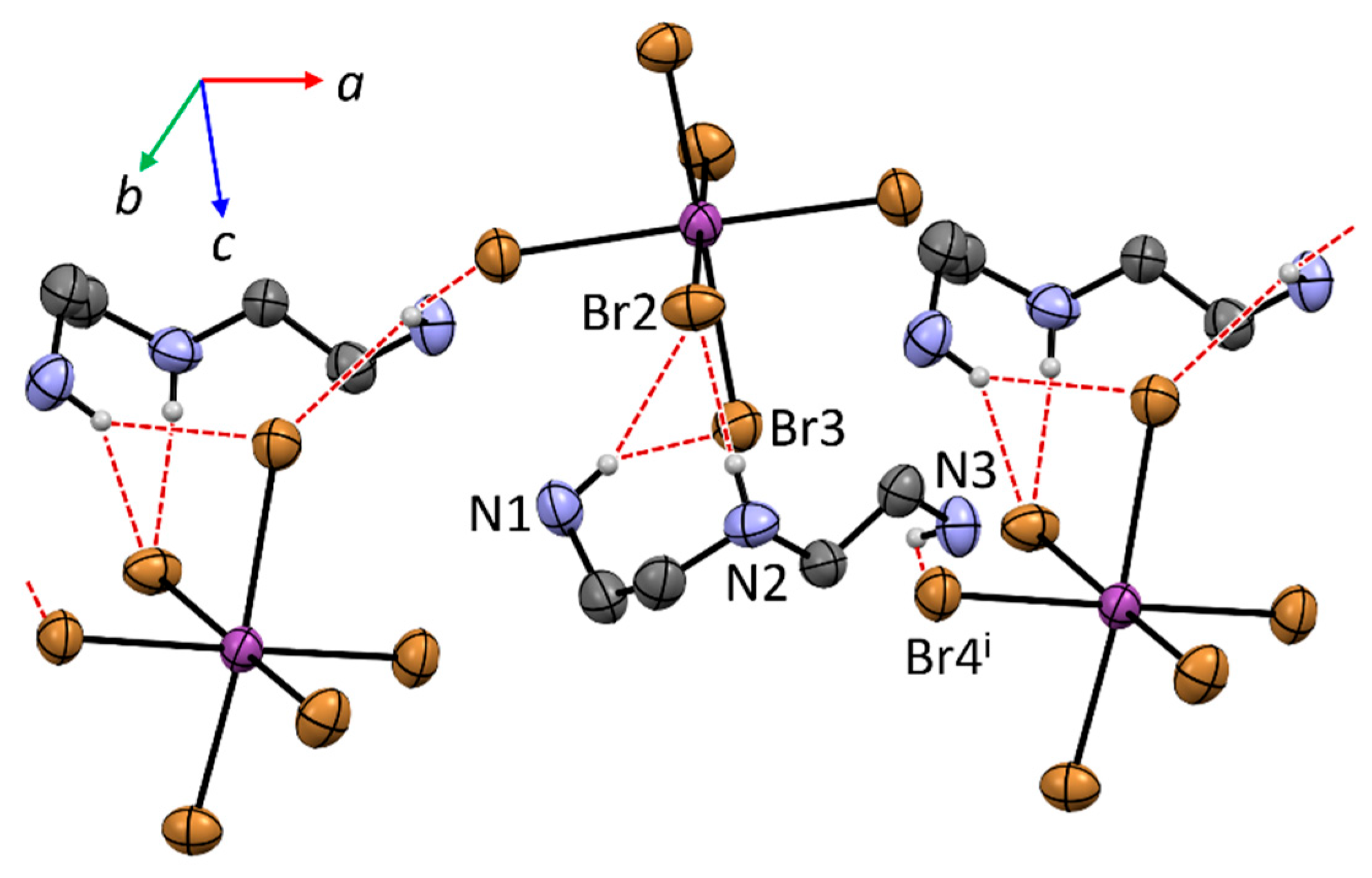
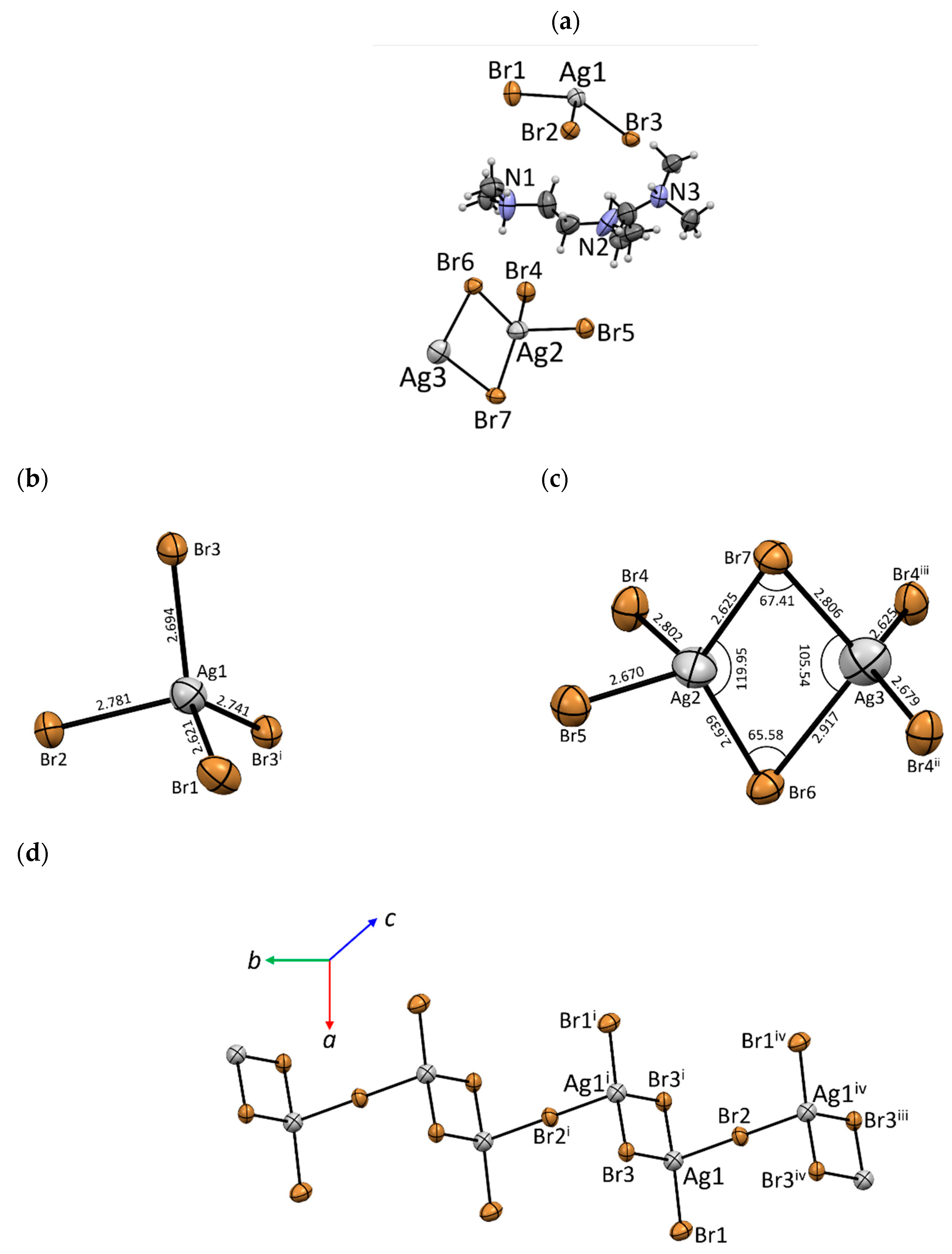
4.2. Crystal Structure Description

Compound 1’s crystal structure was presented previously [32], being a 0D perovskite based on a bismuth(III)–bromide complex that crystallizes in the orthorhombic P212121 space group. In this work, the crystal structure will also be deepened and focused in the organic cation. The asymmetric unit is composed of a [BiBr6]3− unit and a triprotonated diethylenetriamine cation, as pictured in Figure 1a. There are no solvent molecules in the crystal structure. The bismuth complex is in a distorted octahedral coordination geometry (see Figure 1b), with bond lengths varying from 2.787 Å to 2.942 Å and the angles slightly deviating from 90° (see Table S1). The H3DETA3+ cation is found in an almost perfect zigzag conformation, meaning all C–C and C–N bonds have an anti conformation. In the cation, all non-hydrogen atoms are close to coplanarity, with an average deviation from the mean plane of 0.1298 Å.
The crystal packing of 1 is dictated by hydrogen bonds. The N–H bonds are connected to various [BiBr6]3− units around the cations (see Table S2). Each bismuth complex is found interacting with six other H3DETA3+ units via hydrogen bonds. The N1 atom is found interacting with three [BiBr6]3− units, the same number as for N2. Two of the bismuth complexes are shared with these nitrogen atoms. On the other hand, the N3 atom has four [BiBr6]3− around it, with only one interacting at the same time with N2 and none with N1. As a result, when viewed along the crystallographic a axis, the complexes and cations are equally alternated in the compound packing (see Figure 2).
Compound 2 is also a 0D perovskite, being a mixed salt, that crystallizes in the monoclinic P21/c space group. The asymmetric unit consists of one [AgBr4]3− anion, three bromide anions, and two H3DETA3+ cations (see Figure 3a). That means the co-crystallization of H3DETA[AgBr4] and H3DETABr3 is essential to form a densely packed structure and to minimize the lattice energy. Additionally, no crystallization solvent molecules were found in the compound. The silver(I) ion is found in a slightly distorted tetrahedral coordination geometry, as highlighted in Figure 3b. The Ag–Br bond lengths ranged from 2.679 Å to 2.867Å and the angles varied from 101.987(18)° to 117.91(2)° (see Table S1). Differently from 1, the H3DETA3+ cation in 2 has all C–C bonds in gauche conformation. The torsion angles for the N–C–C–N set of atoms are 83.30° [N1–C1–C2–N2], 81.92° [N2–C3–C4–N3], 73.56° [N4–C5–C6–N5], and 78.08° [N5–C7–C8–N3].
The crystal packing of 2 is also dictated by hydrogen bonds. The H3DETA3+ cations can interact with both [AgBr4]3− anions and the bromide anions in all three directions (see Table S3). As a result of the hydrogen bonds, a layered pattern is observed along the crystallographic c axis. This sequence alternates between a layer of bromide anions, followed by a double layer of H3DETA3+, with the [AgBr4]3− anions mediating the interaction with the cations. The crystal packing of 2 is shown in Figure 4.
Compound 3, similarly to compound 1, is also a 0D perovskite based on a bismuth(III)–bromide complex that crystallizes in the orthorhombic P212121 space group. The asymmetric unit of 3 is, as in compound 1, composed of one [BiBr6]3− unit and one triprotonated amine cation, in this case, H3PMDTA3+, as pictured in Figure 5a. The bismuth complex is in a distorted octahedral coordination geometry (Figure 5b), with bond lengths varying from 2.787 Å to 2.942 Å and the angles slightly deviating from 90° (see Table S1). The H3PMDTA3+ in this compound has one of its C–C bonds found in an anti conformation [N2–C3–C4–N3 torsion angle of 9.91°] and one in gauche [N1–C1–C2–N2 torsion angle of 67.49°]. On the other hand, all C–N bonds are in an anti conformation. The torsion angles around C–N bonds are 5.99° [C5–N1–C1–C2], 63.70° [C6–N1–C1–C2], 1.50° [C1–C2–N2–C7], 67.73° [C7–N2–C3–C4], 66.25° [C3–C4–N3–C8], and 8.77° [C3–C4–N3–C9].
The crystal packing of 3 is primarily governed by classic hydrogen bonds (see Table S4). Each H3PMDTA3+ cation interacts via N–H···Br hydrogen bonds to two [BiBr6]3− units, as seen in Figure 6. It forms a 1D supramolecular structure, parallel to the crystallographic a axis. The 1D supramolecular polymers interact with the neighboring chains via C–H···Br weak hydrogen bonds, involving both CH3 and CH2 groups found in H3PMDTA3+, leading to supramolecular interactions in the other directions, granting packing in all directions.
Compound 4 crystallizes in the centrosymmetric orthorhombic Pbcn space group, with its asymmetric unit depicted in Figure 7a. It is a mixed 1D/2D perovskite built from silver(I) and bromide ions. To achieve charge balance, H₃PMDTA3+ cations are present. In the 1D coordination polymer, the silver(I) atom adopts a distorted tetrahedral coordination geometry (see Figure 7b and Table S1) with three of its bromide atoms acting as bridging ligands, as seen in Figure 7d. The bromide atom Br2 connects two silver(I) tetrahedra, forming a linear bridge [Ag1–Br2–Ag1ii = 180°, ii = 3/2–x, –1/2+y, z]. The bromide Br3 creates double bridging between the silver(I) atoms, resulting in an edge-sharing tetrahedral motif, presenting a narrow bond angle of 71.32(2)° [Ag1–Br3–Ag1i, i = 1–x, 2–y, 1–z]. Similarly, the 2D coordination polymer has all silver(I) atoms in a tetrahedral coordination geometry (see Figure 7c,e). One of the bromides, Br5, is found in an almost linear bridging arrangement [155.39(9)° for Ag2–Br5–Ag3], while Br6 and Br7 form a double bridge with a narrow bond angle [Ag2–Br6–Ag3 = 65.58(4)° and Ag2–Br7–Ag3 = 67.41(4)°], and Br4 connects three silver(I) atoms in a T-shaped geometry (see Table S1). The combination of these bonds results in a 2D structure with a 10-membered Ag6Br4 macrocyclic ring, where H3PMDTA3+ is found filling the ring void. The positioning of the H₃PMDTA3+ cations, occupying the voids of the 2D polymer and the spaces between the 1D chains, is shown in Figure 8a. Similarly to compound 3, the cation has a C–C bond in anti conformation and the other one in gauche, and both C–N bonds are in gauche conformation. The torsion angles for C–C bonds are 3.90° [N1–C1–C2–N2] and 59.77° [N2–C3–C4–N3]. C–N torsion angles are 68.81° [C5–N1–C1–C2], 25.75° [C6–N1–C1–C2], 67.38° [C7–N2–C1–C2], 8.41° [C7–N2–C3–C4], 59.47° [N2–C3–C4–N3], 64.45° [C8–N3–C4–C3], and 70.62° [C8–N3–C4–C3]. This cation interacts via N–H···Br hydrogen bonds with both the 1D and 2D coordination polymers, which bind the components into a continuous three-dimensional supramolecular structure (see all hydrogen bonds’ geometry for this compound in Table S5). In this supramolecular motif, each unit is packed, forming an alternated pattern along the crystallographic c axis. The pattern is composed by a 2D polymer, followed by a H3PMDTA3+ layer, then a layer of 1D polymers, and finally another H3PMDTA3+ layer, as shown in Figure 8b.

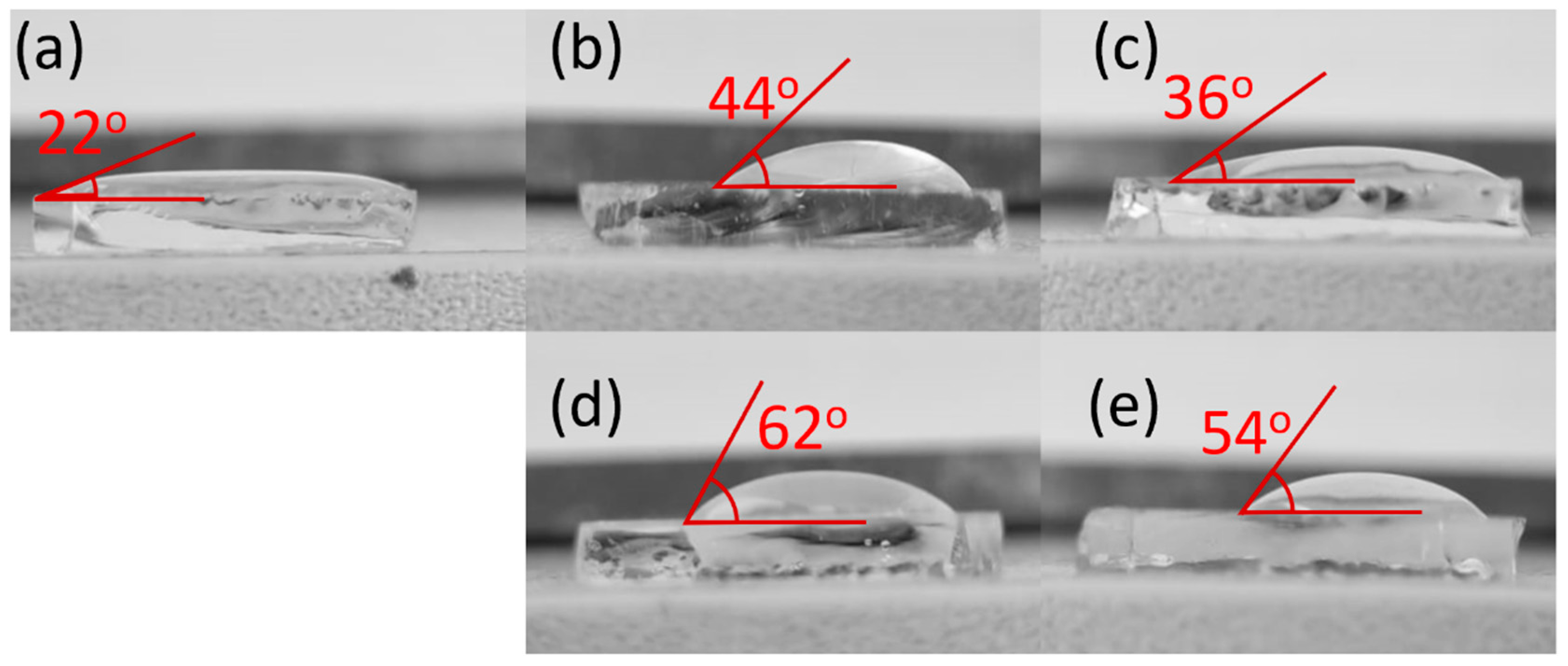
4.3. Film Deposition and Water Affinity

All compounds were successfully deposited on FTO, forming colorless films, which indicates their deposition will not interfere in the light absorption of the resulting device. The pristine FTO-coated glass exhibited a contact angle of 22°, indicating strong hydrophilicity. Upon the deposition of films of 1, 2, 3, and 4, the contact angle increased to 44°, 36°, 62°, and 54°, respectively. Contact angle images are shown in Figure 9. Among the H3DETA3+-based compounds, compound 1 shows a higher contact angle than 2, most likely due to the presence of additional bromide anions in the crystal structure, which enhances its interaction with water.
The H3PMDTA3+-based compounds show higher contact angle than the H3DETA3+-based ones. This is attributed to the presence of five methyl groups on the nitrogen atoms, which contribute to increased hydrophobicity. In this respect, compound 3 is more hydrophobic than compound 4. In the crystal packing of 3, the [BiBr6]3− units are surrounded by the organic cations, whereas in 4, he layered supramolecular structure traps the organic moieties within the voids. Thus, the organic moiety in 4 is less available to interact with water.
Experiments were repeated on Cs2AgBiBr6 films deposited on FTO-coated glass, as shown in Figure 10. The pristine perovskite showed a water contact angle of 40°. Compounds 1 and 3 were successfully deposited onto Cs2AgBiBr6 films (see insets in Figure 10), and the contact angles were approximately the same as those observed when deposited directly onto FTO-coated glass. This suggests the presence of a thin film of these compounds over the perovskite layer. Silver-based compounds 2 and 4 required a DMSO/DMF solvent mixture for dissolution. However, this solvent combination dissolved the underlying perovskite layer. Thus, it was not possible to analyze their hydrophobicity on the perovskite film so far.

5. Conclusions

This work presented four bismuth(III) and silver(I) low-dimensional perovskites, three of them being novel compounds. Their syntheses were optimized to obtain single crystals, with particularly good yields for the bismuth-based compounds. All compounds exhibited high thermal stability, which is required for the annealing processes typically applied to perovskite films, being stable up to 180 °C. These compounds were analyzed by single crystal X-ray diffraction. Compounds 1, 2, and 3 are 0D perovskites containing isolated [BiBr6]3− octahedra or [AgBr4] tetrahedra, with H3DETA3+ (1 and 2) and H3PMDTA3+ (3) as the cations. Furthermore, it was observed that compound 2 is a mixed salt, as its asymmetric unit presented two H3DETA3+ cations, with the second forming part of the salt H3DETABr3. Compound 4 is a mixed 1D/2D perovskite in which the silver(I) forms two distinct coordination polymers, both composed of corner- and edge-sharing tetrahedra. All four compounds were deposited onto FTO-coated glass as films, increasing the hydrophobicity of the surface. However, only compounds 1 and 3 could be deposited onto the Cs2AgBiBr6 perovskite film. The film of compound 1 on the perovskite maintained the same contact angle of the pristine perovskite. In contrast, the film of compound 3 made the perovskite surface more hydrophobic, presenting the contact angle slightly higher than when it was deposited directly on FTO-coated glass. These findings contribute to overcoming fabrication challenges associated with the lead-free perovskites that are unstable in humid environments, thereby improving their stability for photovoltaic applications. It is particularly relevant for the promising Cs₂AgBiI₆ perovskite, whose thin films must be fabricated via ion exchange from bromide-based perovskite and which is severely unstable under ambient humidity.

Supplementary Materials

The following supporting information can be downloaded at: https://www.mdpi.com/article/10.3390/compounds5020020/s1, Infrared spectra (Figures S1–S4), TG and DTA curves (Figures S5–S8), tables containing the Main Bond Lengths and Angles (Table S1) and the Hydrogen bond geometry (Tables S2–S5).

Author Contributions

V.C.S. performed the synthesis, film deposition, and hydrophobicity tests. V.C.S. and B.D. performed the chemical characterizations. W.X.C.O. collected the single crystal data and solved and refined the crystal structure. W.X.C.O. guided the students, supervised all the experiments, and was responsible for funding acquisition. V.C.S., B.D., and W.X.C.O. wrote this paper. All authors have read and agreed to the published version of the manuscript.

Funding

Authors are thankful to CNPQ (420443/2018-5) and FAPEMIG (APQ-05311-23) for financial support, as well as to CAPES, CNPQ, and PRPq-UFMG for scholarships. The authors are also thankful to LabCri (http://www.labcri.ufmg.br/) for providing the single crystal and polycrystalline diffraction facilities and the Bioanalytical Facility NEPS-DQ (https://ne.qui.ufmg.br) for all chemical characterizations.

Data Availability Statement

All data are available in the manuscript or Supplementary Information.

Conflicts of Interest

The authors declare no conflicts of interest.

References

  1. NREL Best Research-Cell Efficiency Chart. Available online: https://www.nrel.gov/pv/cell-efficiency (accessed on 24 March 2025).
  2. Kojima, A.; Teshima, K.; Shirai, Y.; Miyasaka, T. Organometal Halide Perovskites as Visible-Light Sensitizers for Photovoltaic Cells. J. Am. Chem. Soc. 2009, 131, 6050–6051. [Google Scholar] [CrossRef] [PubMed]
  3. Li, J.; Cao, H.L.; Jiao, W.B.; Wang, Q.; Wei, M.; Cantone, I.; Lü, J.; Abate, A. Biological Impact of Lead from Halide Perovskites Reveals the Risk of Introducing a Safe Threshold. Nat. Commun. 2020, 11, 310. [Google Scholar] [CrossRef] [PubMed]
  4. Kore, B.P.; Jamshidi, M.; Gardner, J.M. The Impact of Moisture on the Stability and Degradation of Perovskites in Solar Cells. Mater. Adv. 2024, 5, 2200–2217. [Google Scholar] [CrossRef]
  5. Cheng, W.; Zhou, R.; Peng, S.; Wang, C.; Chen, L. Research on Passivation of Perovskite Layer in Perovskite Solar Cells. Mater. Today Commun. 2024, 38, 107879. [Google Scholar] [CrossRef]
  6. McClure, E.T.; Ball, M.R.; Windl, W.; Woodward, P.M. Cs2AgBiX6 (X = Br, Cl): New Visible Light Absorbing, Lead-Free Halide Perovskite Semiconductors. Chem. Mater. 2016, 28, 1348–1354. [Google Scholar] [CrossRef]
  7. Volonakis, G.; Filip, M.R.; Haghighirad, A.A.; Sakai, N.; Wenger, B.; Snaith, H.J.; Giustino, F. Lead-Free Halide Double Perovskites via Heterovalent Substitution of Noble Metals. J. Phys. Chem. Lett. 2016, 7, 1254–1259. [Google Scholar] [CrossRef]
  8. Rajeev Kumar, N.; Radhakrishnan, R. Electronic, Optical and Mechanical Properties of Lead-Free Halide Double Perovskites Using First-Principles Density Functional Theory. Mater. Lett. 2018, 227, 289–291. [Google Scholar] [CrossRef]
  9. Xiao, Z.; Du, K.; Meng, W.; Mitzi, D.B.; Yan, Y. Chemical Origin of the Stability Difference between Copper(I)- and Silver(I)-Based Halide Double Perovskites. Angew. Chem. 2017, 129, 12275–12279. [Google Scholar] [CrossRef]
  10. Filip, M.R.; Liu, X.; Miglio, A.; Hautier, G.; Giustino, F. Phase Diagrams and Stability of Lead-Free Halide Double Perovskites Cs2BB′X6: B = Sb and Bi, B′ = Cu, Ag, and Au, and X = Cl, Br, and i. J. Phys. Chem. C 2018, 122, 158–170. [Google Scholar] [CrossRef]
  11. Creutz, S.E.; Crites, E.N.; De Siena, M.C.; Gamelin, D.R. Colloidal Nanocrystals of Lead-Free Double-Perovskite (Elpasolite) Semiconductors: Synthesis and Anion Exchange to Access New Materials. Nano Lett. 2018, 18, 1118–1123. [Google Scholar] [CrossRef]
  12. Scalon, L.; Szostak, R.; Araújo, F.L.; Adriani, K.F.; Silveira, J.F.R.V.; Oliveira, W.X.C.; Da Silva, J.L.F.; Oliveira, C.C.; Nogueira, A.F. Improving the Stability and Efficiency of Perovskite Solar Cells by a Bidentate Anilinium Salt. JACS Au 2022, 2, 1306–1312. [Google Scholar] [CrossRef] [PubMed]
  13. He, X.; Wang, M.; Cao, F.; Tian, W.; Li, L. Hydrophobic Long Alkyl Chain Organic Cations Induced 2D/3D Heterojunction for Efficient and Stable Perovskite Solar Cells. J. Mater. Sci. Technol. 2022, 124, 243–251. [Google Scholar] [CrossRef]
  14. Davy, M.M.; Jadel, T.M.; Qin, C.; Luyun, B.; Mina, G. Recent Progress in Low Dimensional (Quasi-2D) and Mixed Dimensional (2D/3D) Tin-Based Perovskite Solar Cells. Sustain. Energy Fuels 2021, 5, 34–51. [Google Scholar] [CrossRef]
  15. Hong, K.; Van Le, Q.; Young Kim, S.; Won Jang, H. Low-Dimensional Halide Perovskites: Review and Issues. J. Mater. Chem. C 2018, 6, 2189. [Google Scholar] [CrossRef]
  16. Febriansyah, B.; Li, Y.; Giovanni, D.; Salim, T.; Hooper, T.J.N.; Sim, Y.; Ma, D.; Laxmi, S.; Lekina, Y.; Koh, T.M.; et al. Inorganic Frameworks of Low-Dimensional Perovskites Dictate the Performance and Stability of Mixed-Dimensional Perovskite Solar Cells. Mater. Horiz. 2023, 10, 536–546. [Google Scholar] [CrossRef]
  17. Yao, Y.; Jiang, H.; Peng, Y.; Zhang, X.; Chen, S.; Liu, X.; Luo, J. High-Curie Temperature Multilayered Hybrid Double Perovskite Photoferroelectrics Induced by Aromatic Cation Alloying. J. Am. Chem. Soc. 2021, 143, 15900–15906. [Google Scholar] [CrossRef]
  18. Connor, B.A.; Su, A.C.; Slavney, A.H.; Leppert, L.; Karunadasa, H.I. Understanding the Evolution of Double Perovskite Band Structure upon Dimensional Reduction. Chem. Sci. 2023, 14, 11858–11871. [Google Scholar] [CrossRef]
  19. Chen, J.; Xiao, X.; Chen, Y.; Li, M.; Fang, W.; Yu, Z.; He, B.; Zhai, T.; He, Y. Narrow-Bandgap Mixed 0D/1D Bismuth Bromide Perovskite Hydrate Enabled by Aromatic Ditertiary Ammonium Spacer. Adv. Opt. Mater. 2023, 11, 2300820. [Google Scholar] [CrossRef]
  20. Connor, B.A.; Biega, R.I.; Leppert, L.; Karunadasa, H.I. Dimensional Reduction of the Small-Bandgap Double Perovskite Cs2AgTlBr6. Chem. Sci. 2020, 11, 7708–7715. [Google Scholar] [CrossRef]
  21. Guo, Z.; Ruan, H.; Lin, J.; Sun, F.; Liu, K.; Chen, X.; Zhao, J.; Yuan, W. (BA)10AgBi2Br19: A One-Dimensional Halide Double Perovskite with a Unique Br Trimer. Chem. Commun. 2022, 58, 13337–13340. [Google Scholar] [CrossRef]
  22. Zhu, Z.K.; Zhu, T.; Wu, J.; You, S.; Yu, P.; Liu, X.; Li, L.; Ji, C.; Luo, J. Discovering New Type of Lead-Free Cluster-Based Hybrid Double Perovskite Derivatives with Chiral Optical Activities and Low X-Ray Detection Limit. Adv. Funct. Mater. 2023, 33, 2214660. [Google Scholar] [CrossRef]
  23. Wan, M.Y.; Liu, W.F.; Luo, J.L.; Liao, J.; Wang, F.X.; Wang, L.J.; Tang, Y.Z.; Tan, Y.H. Silver/Antimony-Base Multifunctional Double Perovskite with H/F Substitution Enhance Properties. Inorg. Chem. 2024, 63, 3083–3090. [Google Scholar] [CrossRef] [PubMed]
  24. Pious, J.K.; Muthu, C.; Dani, S.; Saeki, A.; Nair, V.C. Bismuth-Based Zero-Dimensional Perovskite-like Materials: Effect of Benzylammonium on Dielectric Confinement and Photoconductivity. Chem. Mater. 2020, 32, 2647–2652. [Google Scholar] [CrossRef]
  25. Ozório, M.S.; Oliveira, W.X.C.; Silveira, J.F.R.V.; Nogueira, A.F.; Da Silva, J.L.F. Novel Zero-Dimensional Lead-Free Bismuth Based Perovskites: From Synthesis to Structural and Optoelectronic Characterization. Mater. Adv. 2020, 1, 3439–3448. [Google Scholar] [CrossRef]
  26. Zhang, R.; Mao, X.; Yang, Y.; Yang, S.; Zhao, W.; Wumaier, T.; Wei, D.; Deng, W.; Han, K. Air-Stable, Lead-Free Zero-Dimensional Mixed Bismuth-Antimony Perovskite Single Crystals with Ultra-Broadband Emission. Angew. Chem. Int. Ed. 2019, 58, 2725–2729. [Google Scholar] [CrossRef] [PubMed]
  27. Gao, W.; Ran, C.; Xi, J.; Jiao, B.; Zhang, W.; Wu, M.; Hou, X.; Wu, Z. High-Quality Cs2AgBiBr6 Double Perovskite Film for Lead-Free Inverted Planar Heterojunction Solar Cells with 2.2% Efficiency. ChemPhysChem 2018, 19, 1696–1700. [Google Scholar] [CrossRef]
  28. Rigaku OD. CrysAlis PRO 2022, Rigaku: Tokyo, Japan, 2022.
  29. Palatinus, L.; Chapuis, G. SUPERFLIP—A Computer Program for the Solution of Crystal Structures by Charge Flipping in Arbitrary Dimensions. J. Appl. Crystallogr. 2007, 40, 786–790. [Google Scholar] [CrossRef]
  30. Sheldrick, G.M. Crystal Structure Refinement with SHELXL. Acta Crystallogr. C Struct. Chem. 2015, 71, 3–8. [Google Scholar] [CrossRef]
  31. Farrugia, L.J. WinGX and ORTEP for Windows: An Update. J. Appl. Crystallogr. 2012, 45, 849–854. [Google Scholar] [CrossRef]
  32. Dammak, H.; Feki, H.; Boughzala, H.; Abid, Y. Crystal Structure, Vibrational Spectra and Non-Linear Optical Properties of Diethylenetriammonium Hexabromobismuthate: C4H16N3BiBr6. Spectrochim. Acta A Mol. Biomol. Spectrosc. 2015, 137, 1235–1243. [Google Scholar] [CrossRef]
  33. de P. Espínola, J.G.; Martins, E.P.S.; Aguiar, F.P.; Silva, H.R.M.; Fonseca, M.G.; Arakaki, L.N.H.; Teotônio, E.E.S. Thermal Decomposition Study of Bismuth (III) Trichloride Complex with 1,10-Phenanthroline as the Ligand. J. Therm. Anal. Calorim. 2011, 106, 601–606. [Google Scholar] [CrossRef]
  34. Imperatori, P.; Ferro, D.; Piacente, V. Sublimation Study of BiCl3 and of BiBr3. J. Chem. Thermodyn. 1982, 14, 461–472. [Google Scholar] [CrossRef]
  35. Darnell, A.J.; Yosim, S.J. Some Thermodynamic Properties of Solid Bismuth Chloride. J. Phys. Chem. 1959, 63, 1813–1815. [Google Scholar] [CrossRef]
Figure 1. (a) Crystal structure of the asymmetric unit of compound 1, with atomic labeling. Ellipsoids at the 50% probability level. The hydrogen atoms are shown as white spheres and were not labeled for clarity. (b) Bi–Br bond lengths highlighting the distorted octahedral geometry of the [BiBr6]3− complex in compound 1.
Compounds 05 00020 g001
Figure 2. Alternating pattern of H3DETA3+ and [BiBr6]3− units along the crystallographic a axis in compound 1.
Compounds 05 00020 g002
Figure 3. (a) Crystal structure of the asymmetric unit of compound 2, with atomic labeling. Ellipsoids at the 50% probability level. The hydrogen atoms are shown as white spheres and were not labeled for clarity. (b) Ag–Br bond lengths highlighting the distorted tetrahedral geometry of the [AgBr4]3− complex in compound 2.
Compounds 05 00020 g003
Figure 4. Crystal packing of 2 showcasing the layered supramolecular structure along the crystallographic c axis. The H3DETA3+ cations are shown in blue, [AgBr4]3− in red, and the bromide anions in green for clarity.
Compounds 05 00020 g004
Figure 5. (a) Crystal structure of the asymmetric unit of compound 3, with atomic labeling. Ellipsoids at the 50% probability level. The hydrogen atoms are shown as white spheres and were not labeled for clarity. (b) Bi–Br bond lengths highlighting the distorted octahedral geometry of the [BiBr6]3− complex in compound 3.
Compounds 05 00020 g005
Figure 6. One-dimensional supramolecular chain built by hydrogen bonding (dotted red lines) between H3PMDTA3+ and [BiBr6]3−, extending along the crystallographic a axis.
Compounds 05 00020 g006
Figure 7. (a) Asymmetric unit of 4 with atomic labeling. (b) Coordination sphere around Ag1 silver(I) ion with the Ag–Br bonds lengths. (c) Coordination sphere around Ag2 and Ag3 silver(I) ions, an edge-sharing tetrahedral structure with the Ag–Br bonds lengths. (d) The 1D coordination polymer formed by corner-sharing of tetrahedra through Br2 and edge-sharing through Br3 and Br3i, while Br1 acts as a terminal ligand. (e) The 2D coordination polymer formed by corner-sharing via Br4 and Br5; Br6 and Br7 connect tetrahedra by edge-sharing, without terminal ligands. Symmetry codes: i = 1 − x, 2 − y, 1 − z; ii = 3/2 − x, −1/2 + y, z; iii = x, −1 + y, z; iv = 1 − x, 1 − y, 1 − z; vi = x, 1 + y, z; vii = 1 − x, y, 3/2 − z.
Compounds 05 00020 g007aCompounds 05 00020 g007b
Figure 8. (a) Crystal packing of 4 highlighting the H3PMDTA3- cations filling the voids of both the 10-membered ring of the 2D coordination polymer and between the edge-shared tetrahedra of 1D coordination polymer. Symmetry code: iv = 1 − x, 1 − y, 1 − z. (b) The layered packing of 4 along crystallographic c axis. The 2D coordination polymer is shown in red, the 1D coordination polymer in yellow, and H3PMDTA is shown in blue for clarity.
Compounds 05 00020 g008
Figure 9. Water droplets on (a) pristine FTO-coated glass and films on FTO-coated glass of (b) 1, (c) 2, (d) 3, and (e) 4, showing their respective contact angles.
Compounds 05 00020 g009
Figure 10. Water droplets on (a) a Cs2AgBiBr6 perovskite film deposited on FTO-coated glass and on the same film coated with (b) compound 1 and (c) compound 3, showing the respective contact angles. Insets show the regions where the droplets were placed.
Compounds 05 00020 g010
Table 1. X-ray diffraction data collection and refinement parameters for the compounds 1, 2, 3, and 4.
Compound1234
FormulaC4H16N3Br6BiC8H32N6Br7AgC9H23N3Br6BiC18H52N6Br12Ag6
Moiety Formula(C4H16N3)[BiBr6](C4H16N3)[AgBr4]·(C4H16N3)Br3(C9H23N3)[BiBr6](C9H26N3)[Ag4Br7]·(C9H26N3)[Ag2Br5]
MM/gmol−1794.64879.63861.681958.68
T/°C27(2)27(2)27(2)20(2)
λ0.710730.710730.710730.71073
Crystal systemOrthorhombicMonoclinicOrthorhombicOrthorhombic
Space groupP212121P21/cP212121Pbcn
a7.1619(2)12.8135(2)12.5209(3)21.9327(8)
b14.0315(5)8.68440(10)13.2679(3)7.0174(2)
c16.2858(5)21.2648(3)13.2685(4)29.1014(11)
α90909090
β9094.2400(10)9090
γ90909090
V31636.60(9)2359.82(6)2204.24(10)4479.0(3)
Z4444
ρ/Mg m−33.2252.4762.6062.910
μ/mm−125.39820.77818.86933.410
F(000)14161656.01564.03616
Reflections collected (Rint)12,523 (0.0596)34,634 (0.0365)19,708 (0.0477)41,359 (0.0377)
Independent Reflections4163508645144583
Reflection with I >2σ(I)3498478942103609
R a, wR b [I >2σ(I)]0.0463, 0.10420.0361, 0.09560.0317, 0.06950.0676, 0.1539
R a, wR b (all data)0.0600, 0.10890.0378, 0.09710.0354, 0.07050.0882, 0.1649
S c1.0441.0671.0421.112
ρmax and ρmin/e Å−31.263, –2.6550.789; –1.1451.010, –1.4922.760, –1.837
CCDC number2,434,4472,434,4482,434,4492,434,450
a R= Σ ||Fo| − |Fc||/Σ |Fo|. b wR = [Σ w(|Fo|2 − |Fc|2)2w|Fo|2]1/2. c S = [Σ w(|Fo|2 − |Fc|2)2/(nonp)]1/2, where w ∝ 1/σ, no = observed, and np = fitted parameters.
Disclaimer/Publisher’s Note: The statements, opinions and data contained in all publications are solely those of the individual author(s) and contributor(s) and not of MDPI and/or the editor(s). MDPI and/or the editor(s) disclaim responsibility for any injury to people or property resulting from any ideas, methods, instructions or products referred to in the content.

