Abstract
The nitrogen bond in chemical systems occurs when there is evidence of a net attractive interaction between the electrophilic region associated with a covalently or coordinately bound nitrogen atom in a molecular entity and a nucleophile in another, or the same molecular entity. It is the first member of the family of pnictogen bonds formed by the first atom of the pnictogen family, Group 15, of the periodic table, and is an inter- or intra-molecular non-covalent interaction. In this featured review, we present several illustrative crystal structures deposited in the Cambridge Structure Database (CSD) and the Inorganic Crystal Structure Databases (ICSD) to demonstrate that imide nitrogen is not the only instance where nitrogen can act as an electrophilic agent. Analysis of a set of carefully chosen illustrative crystal systems shows that a covalently bound nitrogen atom in a variety of molecular entities features a σ-hole or even a π-hole, and these have the ability to sustain attractive engagements with negative sites to form inter- and/or intramolecular interactions that drive, or assist, the formation of a crystalline phase.
1. Introduction
IUPAC definitions, features and characteristic properties that can be used to identify non-covalent interactions, such as hydrogen bonding, chalcogen bonding and halogen bonding in chemical systems have been promulgated in 2011 [1], 2013 [2] and 2019 [3], respectively. A task group has been charged with categorizing tetrel bonding, pnictogen bonding, and other non-covalent interactions, involving the elements of Groups 14–16 of the periodic table [4]. The proposed characteristics of these bonding interactions have emerged from observations of a variety of engineered chemical systems in the crystalline, liquid and gas phases, and examining signatures arising from IR [5,6], Raman [7,8], UV/vis [9,10], and NMR [10,11] methods, and from ab initio and density functional theory calculations [12,13,14]. The characteristic features vary from system to system because they are dependent on the nature of the electron density distribution associated with the electron donor and electron acceptor fragments driving the non-covalent interactions.
In this featured review, we show that nitrogen in molecular entities can act as an electrophile when covalently bonded with appropriate electron-withdrawing atomic domain(s). This electrophilic feature of N can form nitrogen-centered pnictogen bonding interactions (or simply nitrogen bonding interactions) when in close proximity with a negative site on the same or a neighboring molecule, and hence is responsible in part for the stability of the resulting supermolecular or intramolecular entity.
The nitrogen bond in chemical systems occurs when there is evidence of a net attractive interaction between the electrophilic region associated with a covalently or coordinately bound nitrogen atom in a molecular entity and a nucleophile in another, or the same molecular entity. It is the first member of the family of pnictogen bonds formed by the first atom of the pnictogen family, Group 15, of the periodic table, and is an inter- or intra-molecular non-covalent interaction.
A nitrogen bond in a molecular entity may be regarded as a σ-hole centered pnictogen bond, especially when the covalently bound nitrogen features a positive σ-hole along the R–N bond extension, where R is the remainder of the molecular entity and is in attractive engagement with a negative site in the same or a neighboring molecule. A σ-hole is defined as a charge density deficient region on an atom A that appears along the outer extension of the R–A covalent bond [15,16]. By contrast, a nitrogen bond may be regarded as a π-hole centered pnictogen bond when the nitrogen in molecular entities features a π-hole [17] on its electrostatic surface and has the ability to engage attractively with a negative site in a neighboring molecule, or a site that has an electron density different to that of the π-hole, thus providing stability to the geometry of the resulting structure. A σ-hole interaction in a chemical system is generally observed to be directional, whereas a π-hole is non-directional. There are many studies on σ-hole and π-hole [17] interactions in chemical systems, including similarities, differences, controversies and misconceptions [18,19,20,21,22,23,24,25].
Nevertheless, nitrogen is a crucial constituent in the development of high-density materials, and, of course, is crucial for ammonia synthesis [26,27,28,29]. Apart from its well-known use as a feedstock for the production of fertilizers [30], we may be on the brink of a viable ammonia economy [31]. “Green ammonia” is a carbon-free hydrogen-containing compound with immense interest due to its high density and high hydrogen storage capability [29,32,33,34].
We considered nitrogen because a fundamental understanding of its modes of interaction in forming complex chemical systems would surely elevate our current knowledge of nitrogen-centered pnictogen bonding (i.e., nitrogen as a pnictogen bond donor). The role of pnictogen bonding containing heavier members of the pnictogen family (viz. P, As, Sb and Bi) in catalysis has also been demonstrated on several occasions [35,36,37,38], and in other areas, such as anion transport and recognition chemistry [39], solution and gas-phase chemistry [40,41,42], computational chemistry [13], supramolecular chemistry [43], coordination chemistry [44,45], medicinal chemistry [46], crystallography [47,48] and crystal engineering [49,50], among other research fields.
Nitrogen is the lightest member of the pnictogen family (Group 15), and the third most electronegative element after fluorine and oxygen. When it is present in a molecular entity, it is well known to be a site for interaction with electrophiles [51]. HCN, N2, NO, HCCCN, CH3CN, and are a few examples where nitrogen is entirely negative, and hence, serves as a site to interact with electrophiles to form molecular complexes in the gas phase or adducts in the solid state. Nitrogen in molecules, such as NH3 and in amines, is often found, both experimentally and theoretically [52,53], to be negative. This is a consequence of its strong electronegative character. It is also less polarizable than the other members of the pnictogen family. Its lone-pair electrons, if visualized from a Lewis structure viewpoint, dominate along the extension of the R–N covalent bonds in compounds in which it is covalently bonded and is an electron density donor towards electrophiles, forming hydrogen bonds, halogen bonds or chalcogen bonds, and acts as a Lewis base to metal ions [54]. This is the probable reason why fluorine, oxygen and nitrogen—being highly electronegative but with low polarizability—often have a negative σ-hole [21]. However, under certain circumstances, nitrogen can act as an acceptor of electron density, for example, in hypervalent non-covalent interactions, as demonstrated by Chandra and coworkers [55]. They observed an intermolecular interaction between nitromethane, CH3NO2 and NH3 at low temperature within an inert gas matrix, which was characterized by IR spectroscopy and supported by first-principles calculations. The nitrogen in CH3NO2 acts as an electron density acceptor from the nitrogen in NH3, forming a CH3O2N···NH3 dimer and is stabilized by an N···N pnictogen bond. The directional prevalence of this interaction over the C–H···N and N–H···O hydrogen bonding interactions was shown by ab initio calculations, demonstrating that σ-hole/π-hole driven interactions lead to the formation of the dimer, despite nitrogen’s low polarizability.
Presented in this review are a set of illustrative crystal systems, demonstrating that nitrogen in the molecular entities that comprise these crystal systems serves as a nitrogen bond donor (electrophilic), and hence is responsible (at least in part) for their geometric stability and functionality. It should be noted that the definition and characteristic features of pnictogen bonding are yet to be formalized, and the term “pnictogen bonding” has come into use only relatively recently [56,57,58,59]. The origin and etymology of the terms pnictogen (also sometimes referred to as pnigogen or pnicogen) and pnictide can be traced back to a suggestion by the Dutch chemist Anton Eduard van Arkel (1893–1976) in the early 1950s [60]. Unsurprisingly, therefore, the characteristic (geometric) features of pnictogen bonding in several crystal structures re-examined in this work were not formally identified and characterized by the original workers who had reported the crystals. Our search of the Cambridge Structure Database (CSD) [61] and the Inorganic Chemistry Structure Database (ICSD) [62] produced hundreds—if not thousands—of structures in which nitrogen could conceivably feature a positive site. This was speculated upon based on the directional feature, together with the intermolecular distance of separation. It is worth mentioning that pnictogen bonds have been known since the middle of last century—if not formally identified and named as such—as have halogen and hydrogen bonds, and were certainly not first described only in 2011, as has been asserted [63].
The characterization of non-covalent interactions in many crystal structures has been undertaken based on the “less than the sum of the van der Waals (vdW) radii” concept [64], a widespread concept that has been invoked, for example, in structural and supramolecular chemistry [64,65,66], biological and medicinal chemistry [67,68], and crystallography [69,70,71,72,73,74]. According to this concept, when the inter- or intramolecular distance of separation is associated with a structural motif, for example, Pn···D (Pn = the pnictogen atom; D = an electron donor, such as O, N, a halogen anion, etc.), is less than the sum of the vdW radii of Pn and D, then it possible that Pn and D atomic basins are bonded to each other by an attractive engagement. This bonding has been referred to as a “close contact”, or simply “a non-covalent interaction” [75]. The criterion, however, rejects those interactions that have intermolecular bond distances slightly larger than the sum of vdW radii of Pn and D. This could be misleading because the proposed vdW radii [76,77] are not necessarily accurate [78] (within an uncertainty of ±0.2 Å) because a spherical symmetry of atoms in molecules was generally assumed for their determination [75], and that there have been many systems reported theoretically and experimentally that fail to strictly obey the criterion [79,80,81,82,83]. Since the charge density profile of atoms in molecules is anisotropic, the vdW “radius” of an atom in a molecular entity is likely to vary between molecular entities. As several have suggested previously [66,75,77,84], we recognize a potential non-covalent interaction between interacting atomic basins even when the interaction distance is greater by several tenths of an Ångstrom than the sum of the respective vdW radii of bonded atomic basins. While doing so, directional features, together with chemical intuition and interpretations provided by the original authors, were considered. In addition, the underlying concepts of molecular electrostatic surface potentials (MESP) [79,80,81,82,83] were utilized in several instances to verify the putative interactions that emerged from the “less than the sum of the vdW radii” concept.
Given the sheer number of candidate structures available in the CSD and ICSD, we decided not to attempt a statistical analysis to delineate the possible occurrence and range of bond distances and angles of approach featuring intermolecular contracts formed between a nitrogen atom and other interacting atomic domains. To do so, one would have to carefully inspect each and every structure to observe whether nitrogen in those crystals does indeed have a positive site; chemical intuition alone does not suffice, and the results could be misleading without extensive computational work. Our search of, for example, the CSD, resulted in thousands of crystals, especially when the intermolecular distance and the angle associated with the motif R–N···X (R = any atom of the periodic table; X = O, N, C, F, Cl, Br, and I, etc.) were constrained to the range of 2.5–3.9 Å and 150°–180°. When we inspected the structures, it was found that (1) a large body of them comprises primary, secondary and tertiary interactions, and (2) many of them also comprise N that feature a negative site and is engaged in hydrogen bonding, (3) and many of them contain structures with missing H atoms or overlapping molecular fragments, such that it was very difficult to draw any conclusion about whether N could be a pnictogen bond donor in the crystals above. However, when the distance and angle criteria associated with the motif were restricted to the ranges, 2.8–3.9 Å and 170°–180° (or 3.0–3.5 Å and 170°–180°) (or 3.3–3.7 Å and 175°–180°), the number of hits in the CSD search was greatly reduced to a few hundred. This enabled us to visually scan most of the crystal structures and to select those where nitrogen-centered pnictogen bonding was likely to occur. We, therefore, emphasize that the examples given below are not exhaustive, but illustrative, since our ultimate aim is to inform the reader of the potential significance of nitrogen-centered pnictogen bonding in crystals so that this can be borne in mind when new materials are designed in silico.
2. Computational Details
We energy-minimized several monomeric entities responsible for the illustrative crystal systems chosen for this review, using density functional theory at the ωB97XD [85] and second-order Møller–Plesset (MP2) levels of theory [86]. For reasons described below, basis sets, such as Jorge-ATZP (where ATZP is the augmented triple-ζ plus polarization basis set), Aug-CC-pVTZ and def2-TZVPD were chosen.
The MESP calculations were performed on the fully relaxed geometries of the monomeric entities in the gas phase. This was done to provide insight into the possible ability of these entities—when in close proximity to another similar (or different) entity—to interact attractively with the partner species, causing or assisting in the formation of a supermolecular assembly. Specifically, we computed the local most minimum and maximum of potential, VS,min and VS,max, respectively, on their electrostatic surfaces. The 0.001 a.u. (electrons bohr−3) isoelectron density envelope that arbitrarily defines the van der Waals surface of a molecular entity was used on which to compute the electrostatic potential [87,88,89]. We used the sign and magnitude of these potentials to infer whether specific regions on the surfaces of these molecular entities are electrophilic or nucleophilic [51,89,90,91].
Accordingly, we utilized the following concepts to provide insight into the way a specific site in a molecular entity makes an attractive engagement with another site in another similar, or different, molecular entity, contributing to the formation of the crystal lattice. A specific region on an atom in a molecular entity was considered to be electrophilic when the sign of either VS,min or VS,max was positive, i.e., VS,min > 0 or VS,max > 0. When they are negative, VS,min < 0 or VS,max < 0, then the region was considered to be nucleophilic [92,93,94].
An intermolecular, or intramolecular interaction, generally occurs (but not always) when a region of an atom or fragment with a positive VS,min (or VS,max) is in close proximity to that with a negative VS,min (or VS,max). For instance, σ-holes on an atom A in a molecular entity along an extension of the bond R–A are generally associated with VS,max and lone-pair, and π-holes with VS,min. Clearly, the nucleophilic portions of a given entity interact attractively with the regions of the most positive electrostatic potential on a neighboring (or the same) entity, leading to σ···lone-pair, σ···π, σ···σ and π···π interactions. This is the case for interactions that are coulombic in origin (a positive site attracting a negative one [54,80,95]). However, there are examples known in which anti-electrostatic interactions have been shown to occur [96,97], as well as instances where a positive site attracts a positive site [98], and a negative site attracts a negative site [51] when they are in close proximity. Although this has been suggested to be a consequence of electrostatic polarization [99,100,101,102,103], dispersion plays a significant role in stabilizing such interactions [25,89,98]. Other researchers also used a similar methodology for theoretical studies of non-covalent interactions in other chemical systems [104,105,106,107,108].
We employed the concepts of Type-I, Type-II and Type-III geometric topologies of bonding (Scheme 1) to characterize nitrogen-centered pnictogen bonds in the crystals illustrated in this overview [24,94].
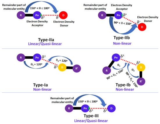
Scheme 1.
Geometric topology of chemical bonding interactions formed by the pnictogen atom in molecular complexes and crystals, where Pn, D, R and R’ refer to the covalently bound pnictogen atom, the interacting atomic domain (generally nucleophilic), and the remaining part of the molecular entities associated with Pn and D atomic basins, respectively. δ± signifies the local polarity (positive or negative), and the small region on atom Pn along R–Pn bond extension colored in green indicates a σ-hole.
The electronic structure calculations were performed using the Gaussian 16 program package [109]. The Mercury 4.0 [110], Gaussview 5.0 [111], AIMAll [112], Multiwfn [113], and VMD [114] suite of programs were utilized for the analysis and drawing.
3. Illustrative Chemical Systems in the Crystalline Phase
3.1. The Solid-State Structure of Dinitrogen, N2
We begin by looking at dinitrogen itself. Solid N2 displays exceptional polymorphism under extreme conditions. Some of its known phases include α, β, γ, δ, ε, ι and θ [115,116,117]. Because the phases of the crystal depend on an external agency (temperature and pressure), the packing is different in each phase. Consequently, the intermolecular interactions between the N2 molecules in these crystals are different.
The α-phase (third allotrope) of solid N2, with Z = 4, space group Pa-3, Figure 1a, determined using electron diffraction measurements [118], is mainly stabilized by π···N (lone-pair) interactions between the N2 molecules. The centers of the N2 molecules are on an f.c.c. lattice with each molecule pointing in a different direction. The intermolecular distance between N in one molecule and the midpoint of the π bond in a neighboring molecule is 3.565 Å. We attribute this interaction to π-centered pnictogen/nitrogen bonding.
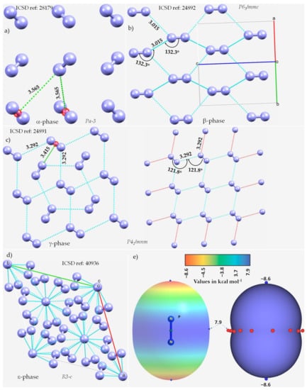
Figure 1.
The nature of bonding interactions between the N2 molecules in the crystals of (a) α-N2, (b) β-N2, (c) γ-N2, and (d) ε-N2. (e) The 0.001 a.u. isodensity mapped MESP plot of an isolated N2 molecule, obtained at the MP2(full)/aug-cc-pVTZ level of theory. The local most minima and maxima of potential are marked by tiny circles in blue and red, respectively. Selected bond lengths and bond angles are in Å and degree, respectively. Crystallographic axes are not shown in (a,c) for clarity. The crystal symmetry is shown for each case, together with ICSD references.
The β-phase of hexagonal N2 (Z = 2), Figure 1b [119], comprises two types of intermolecular bonding modes, including N···N and π···π. The first of these contacts occur between the N2 molecules along the crystallographic c-axis, as shown in Figure 1b, with r(N···N) = 3.015 Å and ∠N≡N···N = 132.3°. It is perhaps a Type-Ib topology of pnictogen bonding. The second type of contact is the result of a slip parallel arrangement between the N2 molecules in the crystal along the crystallographic a and b axes, with an intermolecular distance of 3.861 Å between the centroids of a pair of triple bonds on two neighboring N2 molecules (r(π···π) = 3.861 Å).
The γ-phase of tetragonal N2 (Z = 2), Figure 1c [119], consists of N···N and π···N(lone-pair) interactions. The former ones are longer than the latter. Similar to the β-phase, the N···N contacts follow a Type-Ia topology of bonding, with r(N···N) = 3.292 Å and ∠N≡N···N = 121.8°, but are weaker. The π···N (lone-pair) pnictogen bonded interactions have r(N···π) = 3.415 Å and are stronger than the π···π interactions in β-N2. Regardless of the nature of the intermolecular interactions, they are all marginally shorter or somewhat longer than twice the vdW radius of N, 3.32 Å (rvdW(N) = 1.66 Å [77]).
The ε-phase of rhombohedral N2 (Z = 24), Figure 1d [120], has two types of N≡N···N bond distances, r(N···N) = 2.727 Å and 2.801 Å, corresponding to ∠N≡N···N of 133.1° and 120.9°, respectively, and are less than twice the vdW radius of N, 3.32 Å. Additionally, N(lone-pair)···π interactions may be present between the N2 molecules in the crystal, with r(N···π) = 2.958 Å.
The crystal structures of the high-pressure δ and δ* phases of nitrogen were also investigated using single-crystal X-ray diffraction (not shown) [121]. The structure of the δ phase is isostructurally similar to that of γ-O2. Thus, it comprises spherically disordered molecules, with a preference for avoiding pointing along the cubic ⟨100⟩ directions, and disk-like molecules with a uniform distribution of orientations. The structure of the δ* phase is tetragonal, and the space group was identified unambiguously as P42/ncm at 14.5 GPa.
We did not observe any potentially directional interactions in either of the pressure-induced phases of N2. In all cases, the N···N interactions follow a Type-Ia/Type-Ib topology of bonding and occur between interacting sites of dissimilar electron density. The possibility of the N···N and π···N (lone-pair) interaction can be inferred from the MESP model of an isolated molecule, Figure 1e. The delocalized bonding region in N≡N is equipped with a belt of positive potential characterized by near equivalent local most maxima (tiny red spheres). In contrast to what might be expected on the surface of a covalent bound halogen in a molecular entity, such as, for example, in HBr and HCl, we observed that each N along the N≡N bond extension is accompanied by a local most minima of potential (tiny blue spheres in Figure 1e) and is very negative. This signifies that there is a buildup on charge density on the surface of N along the outer N≡N and the buildup is significant compared to the lateral sites on the same atoms.
3.2. The Nitrogen Trihalides, NX3 and Their Crystal Structures
We now discuss a set of other examples in which covalently bound nitrogen acts as an electrophile, as observed in crystalline systems reported over many years. In these systems, covalently bound nitrogen, as in NX3 (X = F, Cl, Br, I), has a positive region on the R–N bond extension that is capable of attracting a negative site on an identical, or in a different molecule. This can be appreciated by looking at the MESPs shown in Figure 2, obtained using ωB97XD/Jorge-ATZP. The top view of Figure 2 shows nitrogen having a positive electrostatic potential along the X–N bond extensions, regardless of the nature of the halogen derivative attached to it. It is largest (16.6 kcal·mol−1) along the F–N bond extensions in NF3. As one passes from NF3 through NCl3 to NBr3, there is a decrease in VS,max from 16.6 kcal·mol−1 to 5.4 kcal·mol−1 to 2.7 kcal·mol−1, and the stability of the σ-hole on N in NX3 occurs in the order X = F > Cl > Br. By contrast, the lone-pair dominated region on N is negative, and the negativity increases in the order NF3 (−4.1 kcal·mol−1) > NCl3 (−11.8 kcal·mol−1) > NBr3 (−14.2 kcal·mol−1). These results demonstrate the amphoteric character of N in NX3.
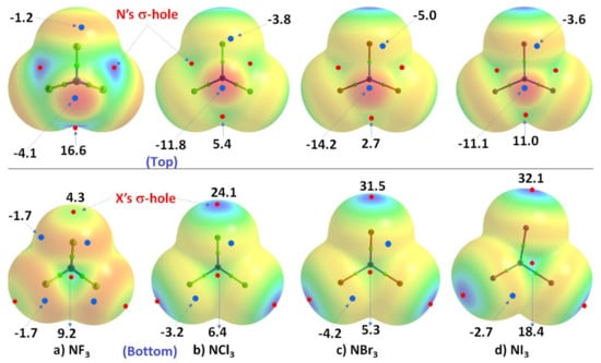
Figure 2.
Comparison of the ωB97XD/Jorge-ATZP calculated 0.001 a.u. isodensity envelope mapped potential on the electrostatic surfaces of NX3 (X = F, Cl, Br, I) molecules. Selected VS,max and VS,min values in kcal·mol−1 are shown, which are the local most maximum and minimum of potential (red and blue circles), respectively. Two views of each MESP graph are shown. In the top view, bonded N faces the reader, whereas, in the bottom view, it is the three halogens that face the reader. The Quantum Theory of Atoms in Molecules (QTAIM [122])-based molecular graph is shown for each entity, with the circles in green representing bond critical points and bonds in atom color.
The MESP results for NI3 are also included in Figure 2, but clearly do not follow the same trend noted above. This may be an artifact of the basis set we used for these calculations, and we clarify this further below. Whilst the numerical values of potential may be out of line, the reactive nature of the N site along and around the I–N bond extensions in NI3 behaves qualitatively similar to that found for the other three NX3 entities.
As shown in the bottom view of Figure 2, VS,max in NX3 increases monotonically from X = F through I along the N–X bond extension, indicating that the magnitude of the σ-holes associated with these potentials increases in the same order and the σ-holes are surrounded by belt-like negative potentials. In other words, the least polarizable F has the smallest σ-hole on N–F bond extensions and the most polarizable I has the largest σ-hole on the N–I bond extensions. The difference in VS,max between NBr3 and NI3 is not large and, as we commented above, the MESP values for NI3 with the chosen basis set used may not be very reliable.
In all cases, the central region of the triangular face formed by the three X atoms in each NX3 is found to be positive. The positive and negative nature of VS,max and VS,min on the surface of each constituent atomic domain in NX3 suggest that each of them not only has the ability to form complexes with another identical (or different) molecule but also has the ability to act both as an acid and a base.
In order to determine whether or not the inconsistency in the nature of the negative and positive regions on the surface of specific atoms in the series of four molecules NX3 is a basis set artifact, we examined the same properties using another basis set, def2-TZVPD, available in the basis set exchange library [123]. We have also adopted a higher level of theory, MP2, for the same calculation as it is one of the simplest and most useful levels of theory beyond Hartree–Fock that accounts for effects arising from electron–electron correlation. The results are summarized in Table 1.

Table 1.
ωB97XD/def2-TZVPD and MP2(full)/def2-TZVPD computed 0.001 a.u. isodensity envelope mapped the local most minima and maxima of potential on the electrostatic surfaces of NX3 (X = F, Cl, Br, I) molecules. VS,max and VS,min values in kcal·mol−1.
As can be seen from the data in Table 1, and regardless of the correlated method used in conjunction with the def2-TZVPD basis set, the N has a positive σ-hole along the X–N bond extensions. These σ-holes become less positive as the size of the halogen in NX3 increases from F down to I, and there are three equivalent holes on N in each NX3. By contrast, the halogen derivative has a single σ-hole on its surface along the N–X bond extension, so there are also three positive σ-holes on the surfaces of the three X atoms that are also equivalent (only one is listed in Table 1). They systematically increase with the increasing size of the halogen in NX3, in agreement with what might be expected from their polarizabilities.
3.2.1. Nitrogen Trifluoride, NF3
The crystal structure of NF3 was reported only recently, and corresponds to the low-temperature α-phase [124]. Since powder neutron diffraction measurements were performed, it is expected that the intermolecular geometry is more accurate than might have been obtained from X-ray diffraction measurements.
The α-phase of NF3 crystallizes in the orthorhombic space group Pnma, with lattice parameters a = 6.71457(13) Å, b = 7.30913(14) Å, c = 4.55189(8) Å, cell volume (V) = 223.396(7) Å3, and Z = 4 at T = 6 K. The β-phase of NF3 corresponds to a high-temperature phase and was observed to be a plastic crystal (space group P4/mnm) with lattice parameters a = 15.334(6) Å, c = 7.820(3) Å, V = 1838.6(12) Å3, and Z = 30 at T = 60 K. It was suggested that the crystal structure of this latter phase is closely related to that of the Frank–Kasper sigma phase, but the one deposited in the ICSD (ref. code 1891641) does not contain the geometry of β-NF3 (the fluorine atoms are missing).
The unit-cell of the α-phase comprises four units of NF3, as shown in Figure 3a. It shows the intermolecular bonding modes between the building blocks responsible for the unit-cell of the NF3 crystal; these are consistent with the attraction between the positive and negative sites of electrostatic potential localized on different atomic domains (Figure 3b). In particular, Type-IIa N–F···F and F–N···F non-covalent interactions are observed and are inferred from the intermolecular distances and angles of interaction. The former is less directional but shorter than the latter (Figure 3a).
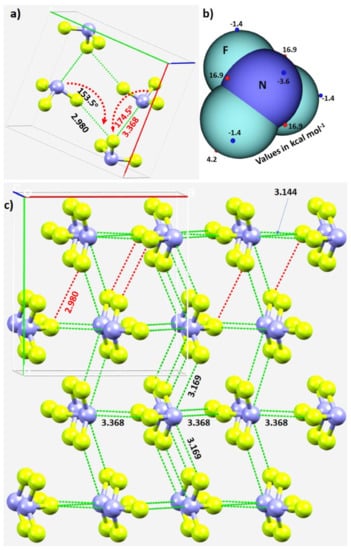
Figure 3.
(a) The unit-cell of α-NF3 (CSD ref. code 1891640), showing selected N···F and F···F σ-hole-centered intermolecular interactions and the intermolecular angles for the approach of the electrophile. (b) Illustration of selected local maximum and minimum of electrostatic potential (red and blue spheres, respectively) mapped on the 0.001 a.u. isoelectron density surface of NF3 obtained at the ωB97XD/aug-cc-pVTZ level of theory. (c) The network of N···F and F···F σ-hole centered pnictogen and halogen bonding interactions in 2 × 2 supercell geometry of α-NF3. Bond lengths and bond angles in Å and degrees, respectively. Dotted lines represent intermolecular interactions.
The real nature of the intermolecular interactions between the molecular units in the crystal may not be apparent in inspecting the unit-cell alone; a periodic extension of the unit-cell is necessary. The 2 × 2 supercell structure of α-NF3 is shown in Figure 3c. Although there are many more interactions between the molecules of NF3 in the crystal, we have highlighted in Figure 3c only the prominent bonding modes formed by the N site. As revealed by the MESP model (Figure 2a), the three positive sites along the F–N bond extensions do indeed donate pnictogen-centered σ-hole bonds to the lateral portions of the F sites in the nearest NF3 units (Figure 3a). Of the three, two are equivalent and the other is longer (3.169 Å vs. 3.368 Å). They are all directional since ∠F–N···F for each of the two equivalent interactions is 172.3° and that for the longer bond is 174.5° (Figure 3a).
In crystalline α-NF3, the nitrogen in the NF3 molecule acts as a hexa-furcated center in donating σ-hole bonds. It donates three highly directional σ-hole bonds (vide supra) and two relatively less directional equivalent σ-hole bonds (r(N···F) = 3.301 Å and ∠F–N···F = 143.4°) that are caused by the attraction between the positive site on the central region of the surface formed by the three fluorine atoms in one molecule and the negative region dominated by the lone-pair of a neighboring molecule, thereby forming five pnictogen bonds (Figure 4a,b). Because nitrogen has a negative site (readily appreciated in its Lewis structure) evidenced by the VS,min = −3.6 kcal·mol−1 shown in Figure 2a, it shows a tendency to accept a σ-hole bond from the covalently bound fluorine of another interacting NF3 molecule, responsible for the formation of an F···N halogen bond (Figure 4b). The back-to-back arrangement between the NF3 molecules, Figure 4a, causing the additional intermolecular interactions noted above, is a result of a π(N)···π(N) interaction. The behavior of N in forming so many non-covalent interactions appears to be unique to this system.
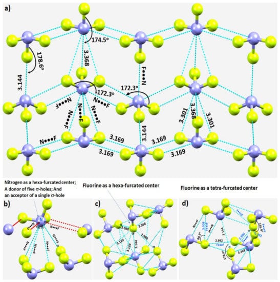
Figure 4.
(a) Nature of N···F pnictogen bonds in the α-phase of the NF3 crystal. (b–d) Nature of the local topology of intermolecular bonding interactions around N and F in NF3. Bond lengths and bond angles in Å and degrees, respectively. The symbol “σ” on N/F in (b–d) refers to the covalently bonded atom donating the σ-hole.
Our investigation shows that fluorine has the ability to act both as a hexa- and tetra-furcated center, as shown in Figure 4c,d, respectively. It is evident from Figure 4c that fluorine is an acceptor of three σ-hole bonds, thus forming one F–N···F and two N–F···F halogen bonds; it is a donor of a single σ-hole bond, forming an N–F···N halogen bond; and it shows capacity to form two or more N–F···F–N halogen-bonded Type-Ia and/or Type-Ib interactions—all within a distance of 2.90–3.20 Å. The Type-Ia N–F···F–N halogen-bonded contacts, such as those marked in Figure 4d, are commonly observed in fully fluorinated compounds, for example, the crystal of C6F6 [125], and in similar compounds [126,127,128]. Clearly, the complex topology of bonding between the NF3 molecules in the crystal structure requires a variety of theoretical studies to detail the nature and the strength of the interactions involved.
3.2.2. Nitrogen Trichloride, NCl3
The crystal structure of NCl3 was reported in 1975 [129]. It crystalizes in the orthorhombic space group Pnma. There are 12 molecules in the unit-cell, as shown in Figure 5a. The mean N–Cl bond distance is 1.75(1) Å and the mean bond angle is 107(2)°. The insights gained from the values of VS,max and VS,min on the surface of an isolated NCl3 molecule above (Figure 2b) can now be used to understand its chemical reactivity.
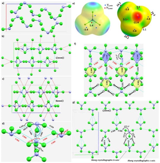
Figure 5.
(a) The unit-cell of the NCl3 crystal (ICSD ref. code: 4034). (b) Illustration of the nature of Cl···Cl intermolecular interactions between the molecular building blocks. (c) Illustration of the nature of the N···Cl interactions. (d) Nature of the local topology of bonding around N in NCl3, showing N is a penta-furcated center. (e) Nature of the reactive sites on the electrostatic surface of the NCl3 molecule responsible for the N···Cl, Cl···N and Cl···Cl interactions, computed with ωB97XD/aug-cc-pVTZ. (f) The nature of various N···Cl and Cl···N interactions in the crystal. (g) The nature of Cl···Cl and Cl···N halogen-bonded interactions in the crystal. Values of bond lengths and bond angles in Å and degrees, respectively.
The N–Cl···N and N–Cl···Cl intermolecular interactions holding the NCl3 molecules together in the crystal can be rationalized by referring to Figure 5b,c, respectively. The extent to which covalently bound N in the NCl3 molecule is engaged with the negative sites on neighboring NCl3 molecules, and producing the observed solid-state structure, is illustrated in Figure 5d. The bonding features are as expected when positive and negative sites on molecular surfaces are in close proximity, inferred from the MESP of NCl3 (Figure 5e).
The pattern of intermolecular interactions between bonded N and Cl in the NCl3 crystal is illustrated in Figure 5f. It is evident that each N donates three σ-holes. Two of these, the attraction between a covalently bonded N in an NCl3 molecule and chlorines on neighboring molecules, generate a zig-zag chain-like pattern. They are inequivalent, in contrast to the analogous interactions observed in the NF3 crystal described above. The r(N···Cl) (∠Cl–N···Cl) for these two contacts are 3.960 Å (160.8°) and 3.894 Å (171.6°), respectively, suggesting a Type-IIa nitrogen bonding topology. The remaining σ-hole bond formed by N, Figure 5d,f, is longer and quasi-linear (r(N···Cl) = 4.358 Å and ∠Cl–N···Cl = 173.2°), and is a result of the packing of molecules in the crystal. As shown in Figure 5d, each N site serves as a penta-furcated center in accepting and donating σ-hole bonds.
The three pnictogen bonds are augmented by σ-centered N–Cl···N and N–Cl···Cl halogen bonds in stabilizing the crystal. These Type-IIa N–Cl···N bonds are highly directional (r(Cl···N) = 3.190 Å and ∠N–Cl···N = 177.1°), and are formed between the σ-hole on the N–Cl bond extension in one molecule and the lone-pair dominated region on N in another interacting molecule (Figure 5g).
The three N···Cl contacts highlighted in yellow in Figure 5f are repeated throughout the crystal. Two of them are equivalent (r(N···Cl) = 3.298 Å) and the other slightly longer (r(N···Cl) = 3.360 Å). They are significantly bent, with ∠Cl–N···Cl of 140.3° and 140.1°, respectively. We assign them to be Type-IIb based on the classification of bonding topology provided in Scheme 1. They are enforced by the attraction between the positive site in the central region of the triangular face formed by three Cl atoms in the NCl3 molecule and the lone-pair dominated negative site on the N of a neighboring molecule. One might characterize this as an N(π)···N(π) pnictogen bond, consistent with the surface extrema revealed by the MESP model (Figure 5e).
Figure 5g shows the pattern of occurrence of Type-IIa N–Cl···Cl halogen bonds. Those having a Cl···Cl bond distance (and ∠N–Cl···Cl) of 3.580 Å (168.4°) are more directional than those with the corresponding values of 3.548 Å (157.6°). Indeed, they are shorter and less directional than Cl···N halogen bonds with bond distances (angles) of 4.305 Å (173.8°), Figure 5g. There are numerous Cl···Cl contacts present in the crystal (not shown).
3.3. Halogen Azides, XN3
Halogen azides XN3 (X = F, Cl, Br, I), crystallographically known for some time [130,131,132,133,134], have also been studied more recently [135,136]. ClN3 forms a chain-like polymer in the solid state, and BrN3, a helical structure, due to the formation of intermolecular Br···Nα and Nβ···Nγ interactions. The unit-cells of IN3 yield structures of polymeric (–I–N3–)n chains that are interlocked into layers, yet two modifications were reported for IN3. Its crystal structure, first determined by X-ray diffraction in 1993 [134], corresponds to the α-phase of the crystal. The second modification of the crystal is called the β-phase [135,137]. Although most of the past studies, including the recent one published in 2021 [137], have determined the lattice constants and important covalent bonding features, which have enhanced our knowledge of covalent p-block azide chemistry, the intermolecular bonding interactions between the XN3 molecules responsible for the crystals are yet to be explored computationally. The study of Schulz and coworkers [135] demonstrates that ClN3 adopts a polymeric structure in the solid state with short intermolecular Cl···Cl distances, as was observed for the elemental halogen. The crystal structures of ClN3 [135], and BrN3 [136], are illustrated in Figure 6a,b and Figure 7a, respectively.
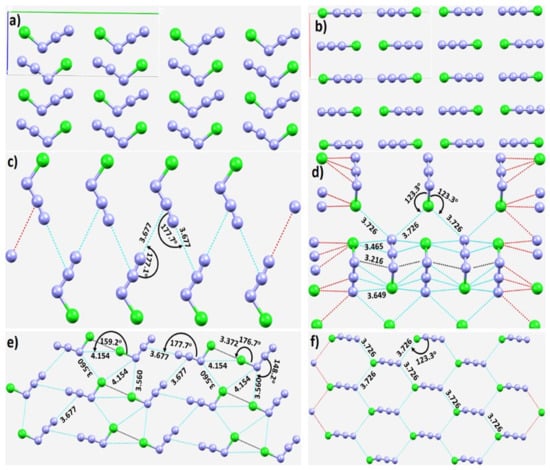
Figure 6.
(a,b) Two different views of the crystal structure of chlorine azide (ICSD ref code: 424502). The nature of (c) π(N)···(N) contacts, and (c,d) a pattern of the π(N)···(N), N···Cl, and Cl···Cl contacts in the crystal. (e) Illustration of Cl···Cl and π···N intermolecular halogen bonding and pnictogen bonding interactions in the crystal. (f) The nature of non-linear Cl···N halogens in the same crystal. Selected bond distances and bond angles are in Å and degree, respectively.
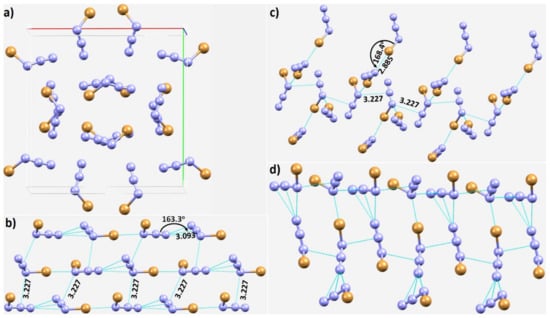
Figure 7.
(a) The crystal structure of bromine azide (ICSD ref code: 423741). The nature of (b) π(N)···(N) and Br···N contacts, and (c) a pattern of the π(N)···(N), and Br···N contacts in the crystal. (d) The nature of non-linear π(N)···(N) pnictogen bonds in the same crystal. Selected bond distances and bond angles are in Å and degree, respectively.
From the resonance structure, the central N atom of in XN3 is expected to be positive; this is indeed what we find with our MESP calculations (vide infra). The calculated VS,max and VS,min are both positive on the surface of this atom, and carry opposite signs for the terminal and covalently bonded N. This explains why the σ-hole on the X atoms in a given XN3 (X = Cl, Br) is directed towards the negative N/X of a neighboring molecule, and why the negative tip on the terminal N atom in a given XN3 is directed towards the positive region on the central N atom of the in another XN3 (see, for example, Figure 6c–f). Both the interaction types are short and significantly linear, with r(π(N)···N) and ∠N=N···N values of 3.677 Å and 177.7° in NCl3 (Figure 6e), respectively, and of 3.093 Å and 163.3° in NBr3 (Figure 7b), respectively. The nature of the intermolecular links between bonded atomic basins can be deduced from Figure 6c–f, including the potential involvement of Type-I and Type-II π(N)···N (Figure 6c–e), and Cl···N and Cl···Cl (Figure 6e,f) nitrogen and halogen bonding interactions. In some cases, a secondary interaction may arise as a consequence of the primary interaction. For instance, the primary Cl···Cl Type-IIa interaction (r(π(N)···N) = 3.372 Å) shown in Figure 6e is likely to be responsible for the development of the Cl···N secondary interactions (r(Cl···N) = 4.154 Å) that are probably very weak.
The packing between the molecular units in ClN3, or BrN3 (Figure 7a), is not very different, and the pattern of intermolecular interactions found in ClN3 is also evident in BrN3. In addition to the observed π(N)···(N) and Br···N pnictogen- and halogen-bonded interactions between the BrN3 units (Figure 7b,c), the slip parallel arrangement between the NBr3 units (Figure 7d), which is also seen in the crystal of ClN3, and which is caused by the attraction between π electron densities, is seen in Figure 7d. Clearly, N–X···N halogen bonding and N=N···N pnictogen bonding interactions play a vital role in the assembly of the molecular units, and hence, in the stability of these azido-based crystals.
The conclusions reached about the reactivity of the surfaces of XN3 molecules above are consistent with the positive and negative signs of the local most minima and maxima of potential, summarized in Table 2. As can be seen from the data, the most positive region is identified on the surface of the central N atom of in XN3 compared to that of the terminal and halogen-bonded nitrogen atoms. The largest values of VS,max are 30.2 and 30.8 kcal·mol−1 in FN3 with ωB97XD and MP2 (full), respectively. This becomes less positive as the size of the halogen increases from F down to I in XN3, a trend that is independent of the correlated method employed. On the other hand, the axial portion of the covalently bonded halogen atom is negative in FN3 but positive in XN3 (X = Cl, Br, I). This is consistent with F in FN3 being significantly less polarizable than the heavier halogens in XN3 (X = Cl, Br, I), as expected from their polarizabilities (F < Cl < Br < I), and explains why covalently bound Cl and Br atoms make σ-hole centered halogen bonding interactions with the negative site centered on the covalently bonded N in a neighboring molecule (see Figure 6e,f and Figure 7b,c for the ClN3 and BrN3 systems, respectively).

Table 2.
ωB97XD/def2-TZVPD and MP2(full)/def2-TZVPD computed 0.001 a.u. isodensity envelope mapped local most minima and maxima of potential on the electrostatic surfaces of XN3 (X = F, Cl, Br, I) molecules. VS,max and VS,min values are in kcal·mol−1. Atom numbering of the moiety in all members of the series is as in FN3.
The MP2(full) and ωB97XD predicted electrostatic potentials are consistent with the conclusions reached above for most regions on the surfaces of XN3, although MP2(full) produces lower values for most sites. A regular trend in a minimum or maximum on the surface of a given molecule is maintained across the series. For instance, the VS,min on the surface of the terminal N along the N=N bond extension in FN3 is calculated with MP2(full) to be negative (−4.3 kcal·mol−1) and is increasingly larger on the same atom in the other three systems of the family as one passes from FN3 to ClN3 to BrN3 to IN3. An anomaly is found on the nature of the lateral portion of the covalently bonded iodine in IN3, for which MP2(full) and ωB97XD have predicted the VS,min associated with it to be slightly positive or close to neutral (0.02 kcal·mol−1) and fully negative (−1.1 kcal·mol−1), respectively. Which one of these is more reliable can only be cross-checked with a computational exploration of the interactions of this site with the negative site on other molecules. Nevertheless, this result unequivocally suggests that the magnitude of electrostatic potential (and sometimes its sign) is dependent on the nature of electron correlation [23,25,89], and hence care should be taken when computing potentials on the electrostatic surfaces of chemical systems. Another way to overcome this is to use a slightly larger isodensity envelope, such as 0.0015 a.u. or 0.0020 a.u., on which to compute the potential. We have discussed the usefulness of these envelopes elsewhere [22,25,87,89].
3.4. Other Azides
Our conclusions about the nature of intermolecular bonding in the halogen azides are consistent with the views of Bursch and coworkers [138] for analogous systems. Specifically, these authors have reported the properties of non-covalent interactions between azides and oxygen-containing moieties in some chemical systems. Representative examples of molecules reported in that study are shown in Figure 8. Each shows close azide–oxygen contacts in the solid state. It was observed that the intramolecular N···O nitrogen bonded contacts are much shorter than the sum of the van der Waals radii of the respective atomic basins. For the Nterminal−Ncentral···X angle (where X is a pnictogen, chalcogen or halogen) in the systems examined, there was a strong accumulation of data points between 85° and 130°. As stated by the authors, caution needs to be exercised in interpreting the angular nature of these interactions because every structure was not individually examined. In the representative structures shown in Figure 8, the Nterminal–Ncentral···O angles are 105.4°, 103,7°, 88.4° and 93.9° for Figure 8a–d, respectively. Although the intramolecular interactions in the representative structures were observed to be unusually bent (perhaps not unexpectedly as they are developed intramolecularly), they are characteristic of pnictogen bonding since the central N atom of the azide moiety in the molecular entities is positive, and is involved in an attractive interaction with the negative sites on covalently bonded O. One may attribute the N···O interaction to a π···lone-pair type pnictogen bond since a p-type orbital on N is responsible for driving this interaction. This may also explain why the directionality of the π-centered pnictogen bond does not follow any specific (linear) topology of bonding. The theoretically calculated association energies for the systems above were reported to be ranged from −1.0 to −5.5 kcal·mol−1.
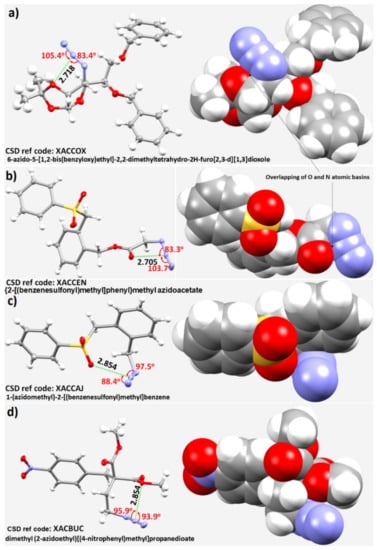
Figure 8.
Representative examples of compounds with close intramolecular oxygen–azide contacts were observed in some structures reported in the solid state [138]; (a) 6-azido-5-[1,2-bis(benzyloxy)ethyl]-2,2-dimethyltetrahydro-2H-furo[2,3-d][1,3]dioxole; (b) {2-[(benzenesulfonyl)methyl]phenyl}methyl azidoacetate; (c) 1-(azidomethyl)-2-[(benzenesulfonyl)methyl]benzene; (d) dimethyl (2-azidoethyl)[(4-nitrophenyl)methyl]propanedioate. Nitrogen is depicted in blue, oxygen in red, sulfur in yellow, and carbon in gray. The interatomic distances between the central N of the azide and the closest oxygen atom are given in Å, and bond angles in degrees. Thermal ellipsoids are shown at the 50% probability level. The names of the molecular entities and CSD ref. codes are shown. The space-filling model is depicted in each case.
The final azide we consider is phosphorus azide, P3N21 [139]. The unit-cell contains two molecules of P3N21. They are bonded to each other through π(N3)···N and N···N non-covalent interactions, as shown in Figure 9a,b. The N···N intermolecular distances range between 2.90 and 3.30 Å, and are all less than twice the van der Waals radius of N, 3.32 Å. Clearly, intermolecular pnictogen bonding is one of the principal features responsible for the formation of the crystalline phase of the P3N21.
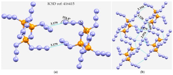
Figure 9.
(a) The crystal structure of 2,2,4,4,6,6-hexa-azido-2,4,6-triphospha-1,3,5-triazine (P3N21) showing π(N3)···N pnictogen bonded interactions. (b) Illustration of N···N and π(N3)···N non-covalent interactions between four molecular units of P3N21. Selected bond lengths and bond angles are in Å and degree, respectively. Nitrogen is depicted in blue, and phosphorous in orange.
3.5. Miscellaneous Examples
We end this section by looking at a number of other examples to illustrate the importance of the involvement of N-centered pnictogen bonding in crystalline materials.
The first is the crystal structure of nitrosium nitrate (NO+), Figure 10a, reported only recently [140], but it is a system that has been studied many times, dating back to 1948 [141,142,143,144,145,146]. The crystalline state, as determined by XRD measurements at high pressure, consists of N≡O+ cations and sp2-trigonal planar anions stabilized via charge-assisted N···π and N···O nitrogen bonding interactions. Our analysis suggests that both N and O in NO+ in the crystal are involved in several intermolecular interactions with the surrounding units. The N of each nitrosonium group has five nearest neighbor O sites from three surrounding units within its inner coordination sphere, with r(N···O) between 2.15 and 2.30 Å (some are shown in Figure 10b,c). Similarly, the O atom of NO+ has five oxygen atoms from four closest units, as its first intermolecular neighbors. The O···O distances vary between 2.27 and 2.36 Å, slightly longer than the N···O bond distances (not shown), as expected since O is slightly larger than N (rvdW (O) = 1.50 Å and rvdW(N) = 1.66 Å) [77]. This analysis is consistent with that of the authors of the study [140]. However, we identified that π-hole(N)···N interactions occur in the crystal at an intermolecular distance of 2.539 Å (see Figure 10b), and are undoubtedly π-hole-centered pnictogen bonds.
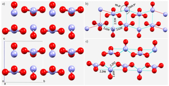
Figure 10.
(a) The crystal structure of monoclinic (P21/m) nitrosium nitrate NO+, CSD ref. code IMABAC. (b,c) Illustration of the nature of π-hole(N)···N and N···O bonding interactions in the crystal, respectively. Selected bond distances and bond angles are in Å and degree, respectively. Atom type is given in (b).
In crystalline tetramethylpyrazinium pentaiodide monohydrate [147], Figure 11, the feasibility of N···I interactions is evident. They are charge-assisted pnictogen bonds, with bond distances in the range 3.7–4.1 Å, and are close to, or longer than, the sum of the vdW radii of N and I, 3.70 Å. They are π-centered since the π-hole on N accepts electron density from the iodine atom in . In addition, there are numerous H···I and (C)π···I type intermolecular interactions that are also responsible for the overall structure of the crystalline material.
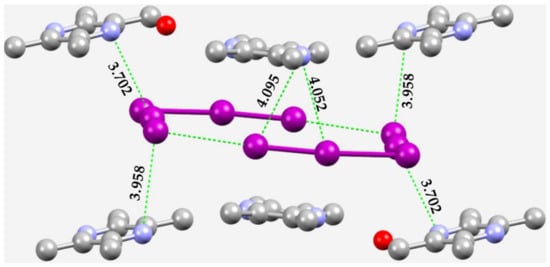
Figure 11.
Illustration of N···I pnictogen bonds in the unit-cell of the crystal of tetramethylpyrazinium pentaiodide (CSD ref. code ZEPBIF). Nitrogen is depicted in blue, oxygen in red, iodine in purple, and carbon in gray. H atoms are not shown for clarity. Selected bond distances are in Å.
Many structures of compounds containing Group 15 elements deposited in the CSD owe their stability to a variety of intermolecular interactions, including pnictogen bonding. Group 15 elements in molecules are often trivalent or tetravalent and hence they may contain more than one σ-hole along the R–Pn bond extensions (viz. as in NX3 shown above). Recently, for instance, Kumar and coworkers [148] suggested that tetrel and pnictogen bonds complement hydrogen and halogen bonds in framing the interactional landscape of barbituric acids. In particular, and by means of a CSD search, these workers have argued that the imide nitrogen atoms in some fluoro-, chloro- and bromo-substituted derivatives of barbituric acid and indandione can act as effective pnictogen bond donors, thereby featuring N···O nitrogen bonds. These contacts appear simultaneously with C···O tetrel bonds, and other interactions, and hence provide stability to the backbone of the overall crystal lattice.
As observed in the crystal structure of NO+ (vide supra), one might speculate that N···O nitrogen bonding interactions occur in the crystal structures of ammonium 1,3,4,6-tetranitro-2,5-diazapentalene, (NH4)2C6N6O8 [149], Figure 12a, and 1,3,4-trinitro-7,8-diazapentalene, C6H3N5O6 [150], Figure 12b, and that N···F pnictogen bonding occurs in the crystal of 3,3-bis(difluoroaminomethyl)oxetane, C5H8F4N2O [151], Figure 12c. In the first two, the N···O interactions are π-centered; the π electron density delocalized on the surface of N of the NO2 fragment in [C6N6O8]2− is in an attractive engagement with the O’s lone-pair in another unit of [C6N6O8]2−. The occurrence of the pnictogen bonded interaction in the crystal is facilitated by charge-assisted H···N hydrogen bonds between NH4+ and the dianion. The N(π)···O interactions are equivalent, with r(N(π)···O) = 2.945 Å, and are less than vdW radii of N and O, 3.16 Å. In the case of the crystal structure of 1,3,4-trinitro-7,8-diazapentalene, C6H3N5O6, there is no ion pair, yet the N(π)···O pnictogen bonded interactions still occur between the C6H3N5O6 units. However, in this case, primary/secondary interactions (viz. H···O hydrogen bonds, and C(π)···O interactions) are expected to play a crucial role in the overall stability of the crystal.
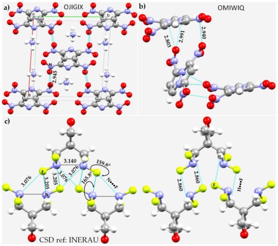
Figure 12.
The nature of nitrogen-centered pnictogen bonding in the crystals of (a) (NH4)2C6N6O8 [149], (b) C6H3N5O6 [150], and (c) C5H8F4N2O [151]. Selected bond distances are shown in Å and degree, respectively. Selected atom types are shown in (a,c) that are involved in making non-covalent interactions. The CSD ref. code is given in each case.
In the crystal of C5H8F4N2O [151] the interacting molecules are bonded to each other through F–N···F nitrogen bonds, Figure 12c (left). They appear to show up in two different flavors: one with an intermolecular bond distance of 3.076 and the other with an intermolecular bond distance of 3.205 Å. The second is directional (∠F–N···F = 165.8°) and follows the Type-IIa topology of bonding and appears along the extension of the F–N covalent bonds. The first is non-linear and is taken to be a π-hole centered interaction (r(N(π)···O) = 3.076 Å). In addition, each monomer unit in the crystal has an N(π)···N(π) pnictogen bonding interaction, with r(N(π)···N(π)) = 3.140 Å. There is a distinct possibility of intermolecular pnictogen bonding in the crystal being driven by H···F hydrogen bonds (Figure 12c, right) that are shorter than the pnictogen bonds. Therefore, the hydrogen bonds are probably the primary intermolecular interaction, leading to the formation of secondary pnictogen interactions in this crystalline material.
The crystal structure of a perhydropyrazolopyrazole is shown in Figure 13a [152]. The N atom in the N–N covalent bond of pyrazole seems to be positive along its outer extension, and the lateral site is negative. This explains why the electropositive H site of the hydroxyl group in an included methanol solvent molecule is able to form a hydrogen bond, leading to the formation of a reasonably strong O–H···N hydrogen bond (r(H···N) = 2.043 Å and ∠O–H···N = 170.9°; Figure 13b). We also observed Type-IIa quasi-linear N···Cl nitrogen bonds in the crystal with r(N···Cl) = 3.958 Å and ∠N–N···Cl = 176.4°, Figure 13b. This emerges from the fact that the lateral site in the covalently bound Cl, which is nucleophilic, interacts with the axial site of N along the N–N bond extensions, and that the interaction is directional. Apart from these interactions, there are numerous π···π stacking interactions, Cl···Cl halogen bonds, and H···Cl hydrogen bonds in the crystal (not explicitly shown).
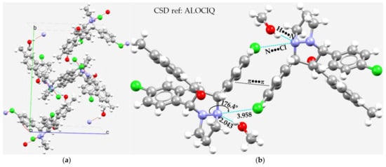
Figure 13.
(a) The nature of N···Cl pnictogen bonding in the unit-cell of the crystal of a perhydropyrazolopyrazole, [1,3-bis(4-chlorophenyl)tetrahydro-1H,5H-pyrazolo[1,2-a]pyrazol-2-yl](4-methylphenyl)methanone [152]. There is a methanol solvate in the structure. (b) The local nature of intermolecular interactions between the monomeric units in the same crystal. Selected bond lengths and bond angles are in Å and degrees, respectively. The dotted lines represent intermolecular interactions, and those in red represent hanging contacts.
Olejniczak and coworkers [153] recently reported crystalline materials formed as a consequence of CH···N and N···N interactions in the high-pressure structures of some pyridazines, viz. 6-azido-1,2,4-triazolo[4,3-b]pyridazine (C5H3N7) (as an anhydrate) and its 3-methyl derivative (C6H5N7) (as a hydrated clathrate). Short C–H···N and N···N intermolecular contacts could be observed in the structures; the latter involves attraction exclusively between the azide groups. Figure 14a shows the unit-cell of the crystal of C5H3N7, and Figure 14b shows the binary arrangement between the C5H3N7 molecular units in the crystal. As shown in the latter, there is a pair each of N···N and H···N close contacts between the two interacting units. The first is more directional than the second and follows a Type-IIa pattern of nitrogen bonding. In addition to these interactions, nitrogen-centered π···π stacking interactions appear to play a very important role in the stability of the crystal, as may be inferred from Figure 14a. The intermolecular distances of the N···N contacts are different, 3.369 and 3.165 Å. The latter is shorter, and the former is longer than twice the vdW radius of N, 3.32 Å, and both are directional.

Figure 14.
(a) The unit-cell of the crystal structure of 6-azido[1,2,4]triazolo[4,3-b]pyridazine (C5H3N7), showing possible N···N close contacts between the interacting monomer units. (b) Illustration of N···N and H···N pnictogen and hydrogen bonds between the pair of two units of C5H3N7. Bond lengths and bond angles in Å and degrees, respectively. The CSD ref. code of the crystal is NETJUR01.
Allcock coworkers [154] have reported the crystal structure of a series of short-chain and cyclic phosphazenes bearing o-dichloro- and o-dimethyl-phenoxy groups. Figure 15a shows one of them, (O)PCl2N=P(o-OC6H3Cl2)3. Within the skeletal framework of the molecular entity, the lateral sites of the ortho-Cl atoms are negative. There is an overlap between the Cl and N atomic basins corresponding to an intermolecular distance of 3.264 Å (Figure 15b), which is less than the sum of the vdW radii of Cl and N atoms, 3.48 Å (rvdW(Cl) = 1.82 Å and rvdW(N) = 1.66 Å). This intramolecular N···Cl close contact is a π-hole centered nitrogen bond. The nitrogen site is also in an attractive engagement with the two nearest C and Cl atoms. The N···C close contact (r(N···C) = 2.901 Å) appears to be a π···π interaction, and the N(π)···Cl close contact with an intramolecular distance of 3.695 Å is a force consequence of the Cl–P···Cl pnictogen bond. The overall stability of the crystal is, however, a result of significant H···Cl and H···O, π···π stacking interactions (between arene moieties), and Cl···Cl halogen-bonded intermolecular interactions that may be deduced from the unit-cell of the crystal itself (Figure 15a).
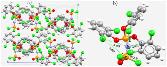
Figure 15.
(a) The unit-cell of crystalline tris(2,6-dichlorophenoxy)phosphazeno-dichloro-oxo-phosphorus, (O)PCl2N=P(o-OC6H3Cl2)3, (CSD ref. code PADJUZ). (b) Illustration of possible intramolecular pnictogen bonding within the framework of the molecular building block. Selected bond distances and bond angles in (b) are in Å and degree, respectively. The selected atom type is depicted.
4. Conclusions
In this featured review, we highlighted the importance and nature of the modes of nitrogen-centered pnictogen bonding (or, simply, the nitrogen bond) observed in many crystals deposited in the CSD and ICSD. Several of them have been known since the last century, even though the term “pnictogen bond”, or even “nitrogen bond” was not coined during that time. They turn out to occur in four different flavors: N(σ)···lone-pair, N(π)···lone-pair, N(σ)···π and N(π)···π(N). The rationalization of these interacting modes was made possible by exploring the MESP of isolated monomers constituting the crystals in several instances, together with chemical intuition. We have shown that the singular occurrence of pnictogen bonding in crystals is very rare, and hence is accompanied or reinforced by other primary/secondary interactions in a great majority of crystals, such as halogen bonds, hydrogen bonds, and/or π···π stacking interactions. Whereas there have been few previous studies reported of pnictogen bonding with covalently bonded nitrogen as an electrophilic agent (viz. imide nitrogen [148]), as the nitrogen in the molecular entity is often observed to be negative, this overview highlighted the local modes of intra- and intermolecular bonding interactions in several examples containing nitrogen that has a positive site. This is expected to guide researchers on future studies of nitrogen-centered pnictogen bonding and the design in silico of novel materials. We did not carry out a statistical analysis of structures deposited in the CSD and ICSD of pnictogen bonding to reveal possible ranges of intermolecular distances and angles of the approach of the electrophile on N in molecular entities, since pnictogen bonding is heavily affected by other primary and secondary interactions. As pointed out by a reviewer, even though a single example would be sufficient proof of existence, stronger arguments can be made if such cases are definitely shown not to be outliers. Since no rigorous theoretical first-principles calculations have been performed on most of the systems highlighted in this study, it is expected that the illustrative crystal systems may be used as model systems to investigate the energy stability and other physio-chemical properties (viz. vibrational frequency shift and NMR chemical shifts) to reveal the characteristic features of pnictogen bonds. The attempt will no doubt help provide a reasonable description of the strength of nitrogen bonds in supermolecular entities.
Author Contributions
Conceptualization, project design, and project administration, P.R.V.; formal analysis and investigation, P.R.V. and A.V.; supervision, P.R.V.; writing—original draft, P.R.V. and A.V.; writing—review and editing, P.R.V., H.M.M., A.V. and K.Y. All authors have read and agreed to the published version of the manuscript.
Funding
This research received no external funding.
Institutional Review Board Statement
Not applicable.
Informed Consent Statement
Not applicable.
Data Availability Statement
This research did not report any data.
Acknowledgments
This work was entirely conducted using the various computation and laboratory facilities provided by the University of Tokyo and the Research Center for Computational Science of the Institute of Molecular Science (Okazaki, Japan). P.R.V. is currently affiliated with the University of the Witwatersrand (SA), and Nagoya University, Aichi 464-0814, Japan; A.V. is currently affiliated with AIST, Tsukuba 305-8560, Japan; K.Y. is currently affiliated with Kyoto University, ESICB, Kyoto, 615-8245, Japan. H.M.M. thanks the National Research Foundation, Pretoria, South Africa, and the University of the Witwatersrand for funding.
Conflicts of Interest
The authors declare no conflict of interest. The funders had absolutely no role in the design of the study; in the collection, analyses, or interpretation of data; in the writing of the manuscript, or in the decision to publish the results.
References
- Arunan, E.; Desiraju, G.R.; Klein, R.A.; Sadlej, J.; Scheiner, S.; Alkorta, I.; Clary, D.C.; Crabtree, R.H.; Dannenberg, J.J.; Hobza, P.; et al. Definition of the hydrogen bond (IUPAC Recommendations 2011). Pure Appl. Chem. 2011, 83, 1637–1641. [Google Scholar] [CrossRef]
- Desiraju, G.R.; Shing Ho, P.; Kloo, L.; Legon, A.C.; Marquardt, R.; Metrangolo, P.; Politzer, P.; Resnati, G.; Rissanen, K. Definition of the halogen bond (IUPAC Recommendations 2013). Pure Appl. Chem. 2013, 85, 1711–1713. [Google Scholar] [CrossRef]
- Aakeroy, C.B.; Bryce, D.L.; Desiraju, R.G.; Frontera, A.; Legon, A.C.; Nicotra, F.; Rissanen, K.; Scheiner, S.; Terraneo, G.; Metrangolo, P.; et al. Definition of the chalcogen bond (IUPAC Recommendations 2019). Pure Appl. Chem. 2019, 91, 1889–1892. [Google Scholar] [CrossRef]
- IUPAC Project: Categorizing Chalcogen, Pnictigen, and Tetrel Bonds, and Other Interactions Involving Group 14–16 Elements. Available online: https://iupac.org/projects/project-details/?project_nr=2016-001-2-300 (accessed on 31 January 2022).
- Bakker, D.J.; Peters, A.; Yatsyna, V.; Zhaunerchyk, V.; Rijs, A.M. Far-Infrared Signatures of Hydrogen Bonding in Phenol Derivatives. J. Phys. Chem. Lett. 2016, 7, 1238–1243. [Google Scholar] [CrossRef] [PubMed]
- Vasylyeva, V.; Catalano, L.; Nervi, C.; Gobetto, R.; Metrangolo, P.; Resnati, G. Characteristic redshift and intensity enhancement as far-IR fingerprints of the halogen bond involving aromatic donors. CrystEngComm 2016, 18, 2247–2250. [Google Scholar] [CrossRef]
- Hardin, A.E.S.; Ellington, T.L.; Nguyen, S.T.; Rheingold, A.L.; Tschumper, G.S.; Watkins, D.L.; Hammer, N.I. A Raman Spectroscopic and Computational Study of New Aromatic Pyrimidine-Based Halogen Bond Acceptors. Inorganics 2019, 7, 119. [Google Scholar] [CrossRef] [Green Version]
- Messina, M.T.; Metrangolo, P.; Navarrini, W.; Radice, S.; Resnati, G.; Zerbi, G. Infrared and Raman analyses of the halogen-bonded non-covalent adducts formed by α,ω-diiodoperfluoroalkanes with DABCO and other electron donors. J. Mol. Struct. 2000, 524, 87–94. [Google Scholar] [CrossRef]
- Shen, Q.J.; Jin, W.J. Strong halogen bonding of 1,2-diiodoperfluoroethane and 1,6-diiodoperfluorohexane with halide anions revealed by UV-Vis, FT-IR, NMR spectroscopes and crystallography. Phys. Chem. Chem. Phys. 2011, 13, 13721–13729. [Google Scholar] [CrossRef] [PubMed]
- Widner, D.L.; Robinson, E.R.; Perez, A.B.; Vang, H.G.; Thorson, R.A.; Driscoll, Z.L.; Giebel, S.M.; Berndt, C.W.; Bosch, E.; Speetzen, E.D.; et al. Comparing Strong and Weak Halogen Bonding in Solution: 13C NMR, UV/Vis, Crystallographic, and Computational Studies of an Intramolecular Model. Eur. J. Org. Chem. 2017, 2017, 5739–5749. [Google Scholar] [CrossRef]
- Hakkert, S.B.; Gräfenstein, J.; Erdelyi, M. The 15N NMR chemical shift in the characterization of weak halogen bonding in solution. Faraday Discuss. 2017, 203, 333–346. [Google Scholar] [CrossRef]
- Gomila, R.M.; Frontera, A. Charge assisted halogen and pnictogen bonds: Insights from the Cambridge Structural Database and DFT calculations. CrystEngComm 2020, 22, 7162–7169. [Google Scholar] [CrossRef]
- De Azevedo Santos, L.; Hamlin, T.A.; Ramalho, T.C.; Bickelhaupt, F.M. The pnictogen bond: A quantitative molecular orbital picture. Phys. Chem. Chem. Phys. 2021, 23, 13842–13852. [Google Scholar] [CrossRef] [PubMed]
- Fanfrlík, J.; Zierkiewicz, W.; Švec, P.; Růžičková, Z.; Řezáč, J.; Michalczyk, M.; Růžička, A.; Michalska, D.; Hobza, P. Pnictogen bonding in pyrazine·PnX5 (Pn = P, As, Sb and X = F, Cl, Br) complexes. J. Mol. Model. 2017, 23, 328. [Google Scholar] [CrossRef] [PubMed]
- Murray, J.S.; Lane, P.; Clark, T.; Riley, K.E.; Politzer, P. σ-Holes, π-holes and electrostatically-driven interactions. J. Mol. Model. 2012, 18, 541–548. [Google Scholar] [CrossRef]
- Clark, T.; Hennemann, M.; Murray, J.S.; Politzer, P. Halogen bonding: The σ-hole. J. Mol. Model. 2007, 13, 291–296. [Google Scholar] [CrossRef] [PubMed]
- Wang, H.; Wang, W.; Jin, W.J. σ-Hole Bond vs. π-Hole Bond: A Comparison Based on Halogen Bond. Chem. Rev. 2016, 116, 5072–5104. [Google Scholar] [CrossRef] [PubMed]
- Zhang, Y.; Wang, W. The σ-hole···σ-hole stacking interaction: An unrecognized type of noncovalent interaction. J. Chem. Phys. 2020, 153, 214302. [Google Scholar] [CrossRef]
- Politzer, P.; Murray, J.S. σ-Hole Interactions: Perspectives and Misconceptions. Crystals 2017, 7, 212. [Google Scholar] [CrossRef] [Green Version]
- Mallada, B.; Gallardo, A.; Lamanec, M.; Torre, B.d.l.; Špirko, V.; Hobza, P.; Jelinek, P. Real-space imaging of anisotropic charge of σ-hole by means of Kelvin probe force microscopy. Science 2021, 374, 863–867. [Google Scholar] [CrossRef]
- Politzer, P.; Murray, J.S. σ-holes and π-holes: Similarities and differences. J. Comp. Chem. 2018, 39, 464–471. [Google Scholar] [CrossRef]
- Varadwaj, A.; Varadwaj, P.R.; Jin, B.-Y. Fluorines in tetrafluoromethane as halogen bond donors: Revisiting address the nature of the fluorine’s σ-hole. Int. J. Quantum Chem. 2015, 115, 453–470. [Google Scholar] [CrossRef]
- Varadwaj, P.R.; Varadwaj, A.; Jin, B.-Y. Halogen bonding interaction of chloromethane with several nitrogen donating molecules: Addressing the nature of the chlorine surface σ-hole. Phys. Chem. Chem. Phys. 2014, 16, 19573–19589. [Google Scholar] [CrossRef] [PubMed] [Green Version]
- Ibrahim, M.A.A.; Moussa, N.A.M. Unconventional Type III Halogen···Halogen Interactions: A Quantum Mechanical Elucidation of σ-Hole∙··σ-Hole and Di-σ-Hole Interactions. ACS Omega 2020, 5, 21824–21835. [Google Scholar] [CrossRef] [PubMed]
- Varadwaj, P.R.; Varadwaj, A.; Marques, H.M. Does Chlorine in CH3Cl Behave as a Genuine Halogen Bond Donor? Crystals 2020, 10, 146. [Google Scholar] [CrossRef] [Green Version]
- Foster, S.L.; Bakovic, S.I.P.; Duda, R.D.; Maheshwari, S.; Milton, R.D.; Minteer, S.D.; Janik, M.J.; Renner, J.N.; Greenlee, L.F. Catalysts for nitrogen reduction to ammonia. Nat. Catal. 2018, 1, 490–500. [Google Scholar] [CrossRef]
- Uyanik, M.; Kato, T.; Sahara, N.; Katade, O.; Ishihara, K. High-Performance Ammonium Hypoiodite/Oxone Catalysis for Enantioselective Oxidative Dearomatization of Arenols. ACS Catal. 2019, 9, 11619–11626. [Google Scholar] [CrossRef]
- Hinokuma, S.; Sato, K. Ammonia Combustion Catalysts. Chem. Lett. 2021, 50, 752–759. [Google Scholar] [CrossRef]
- Lamb, K.E.; Dolan, M.D.; Kennedy, D.F. Ammonia for hydrogen storage; A review of catalytic ammonia decomposition and hydrogen separation and purification. Int. J. Hydrogen Energy 2019, 44, 3580–3593. [Google Scholar] [CrossRef]
- US Geological Survey. Mineral Commodity Summaries 2020; US Geological Survey: Reston, VA, USA, 2020. [CrossRef] [Green Version]
- MacFarlane, D.R.; Cherepanov, P.V.; Choi, J.; Suryanto, B.H.R.; Hodgetts, R.Y.; Bakker, J.M.; Ferrero Vallana, F.M.; Simonov, A.N. A Roadmap to the Ammonia Economy. Joule 2020, 4, 1186–1205. [Google Scholar] [CrossRef]
- Ogasawara, K.; Nakao, T.; Kishida, K.; Ye, T.-N.; Lu, Y.; Abe, H.; Niwa, Y.; Sasase, M.; Kitano, M.; Hosono, H. Ammonia Decomposition over CaNH-Supported Ni Catalysts via an NH2−-Vacancy-Mediated Mars–van Krevelen Mechanism. ACS Catal. 2021, 11, 11005–11015. [Google Scholar] [CrossRef]
- Mukherjee, S.; Devaguptapu, S.V.; Sviripa, A.; Lund, C.R.F.; Wu, G. Low-temperature ammonia decomposition catalysts for hydrogen generation. Appl. Catal. B Environ. 2018, 226, 162–181. [Google Scholar] [CrossRef]
- Rouwenhorst, K.H.R.; Engelmann, Y.; van ‘t Veer, K.; Postma, R.S.; Bogaerts, A.; Lefferts, L. Plasma-driven catalysis: Green ammonia synthesis with intermittent electricity. Green Chem. 2020, 22, 6258–6287. [Google Scholar] [CrossRef]
- Gini, A.; Paraja, M.; Galmés, B.; Besnard, C.; Poblador-Bahamonde, A.I.; Sakai, N.; Frontera, A.; Matile, S. Pnictogen-bonding catalysis: Brevetoxin-type polyether cyclizations. Chem. Sci. 2020, 11, 7086–7091. [Google Scholar] [CrossRef] [PubMed]
- Humeniuk, H.V.; Gini, A.; Hao, X.; Coelho, F.; Sakai, N.; Matile, S. Pnictogen-Bonding Catalysis and Transport Combined: Polyether Transporters Made In Situ. JACS Au 2021, 1, 1588–1593. [Google Scholar] [CrossRef]
- Paraja, M.; Gini, A.; Sakai, N.; Matile, S. Pnictogen-Bonding Catalysis: An Interactive Tool to Uncover Unorthodox Mechanisms in Polyether Cascade Cyclizations. Chem. A Eur. J. 2020, 26, 15471–15476. [Google Scholar] [CrossRef]
- Benz, S.; Poblador-Bahamonde, A.I.; Low-Ders, N.; Matile, S. Catalysis with Pnictogen, Chalcogen, and Halogen Bonds. Angew. Chem. Int. Ed. 2018, 57, 5408–5412. [Google Scholar] [CrossRef]
- Taylor, M.S. Anion recognition based on halogen, chalcogen, pnictogen and tetrel bonding. Coord. Chem. Rev. 2020, 413, 213270. [Google Scholar] [CrossRef]
- Qiu, J.; Song, B.; Li, X.; Cozzolino, A.F. Solution and gas phase evidence of anion binding through the secondary bonding interactions of a bidentate bis-antimony(iii) anion receptor. Phys. Chem. Chem. Phys. 2018, 20, 46–50. [Google Scholar] [CrossRef]
- Legon, A.C. Tetrel, pnictogen and chalcogen bonds identified in the gas phase before they had names: A systematic look at non-covalent interactions. Phys. Chem. Chem. Phys. 2017, 19, 14884–14896. [Google Scholar] [CrossRef]
- Lee, L.M.; Tsemperouli, M.; Poblador-Bahamonde, A.I.; Benz, S.; Sakai, N.; Sugihara, K.; Matile, S. Anion Transport with Pnictogen Bonds in Direct Comparison with Chalcogen and Halogen Bonds. J. Am. Chem. Soc. 2019, 141, 810–814. [Google Scholar] [CrossRef]
- Moaven, S.; Andrews, M.C.; Polaske, T.J.; Karl, B.M.; Unruh, D.K.; Bosch, E.; Bowling, N.P.; Cozzolino, A.F. Triple-Pnictogen Bonding as a Tool for Supramolecular Assembly. Inorg. Chem. 2019, 58, 16227–16235. [Google Scholar] [CrossRef] [PubMed]
- Mahmudov, K.T.; Gurbanov, A.V.; Aliyeva, V.A.; Resnati, G.; Pombeiro, A.J.L. Pnictogen bonding in coordination chemistry. Coord. Chem. Rev. 2020, 418, 213381. [Google Scholar] [CrossRef]
- Mahmudov, K.T.; Huseynov, F.E.; Aliyeva, V.A.; Guedes da Silva, M.F.C.; Pombeiro, A.J.L. Noncovalent Interactions at Lanthanide Complexes. Chem. Eur. J. 2021, 27, 14370–14389. [Google Scholar] [CrossRef] [PubMed]
- Liu, C.; Shin, J.; Son, S.; Choe, Y.; Farokhzad, N.; Tang, Z.; Xiao, Y.; Kong, N.; Xie, T.; Kim, J.S.; et al. Pnictogens in medicinal chemistry: Evolution from erstwhile drugs to emerging layered photonic nanomedicine. Chem. Soc. Rev. 2021, 50, 2260–2279. [Google Scholar] [CrossRef] [PubMed]
- Fanfrlík, J.; Hnyk, D. Dihalogen and Pnictogen Bonding in Crystalline Icosahedral Phosphaboranes. Crystals 2018, 8, 390. [Google Scholar] [CrossRef] [Green Version]
- Sobalev, S.; Matveychuk, Y.; Bartashevich, E. Features of the Pnictogen Bonds Formed by Neighboring Nitro Groups in Crystals. Bull. South Ural State Univ. Chem. 2019, 11, 66–75. [Google Scholar] [CrossRef] [Green Version]
- Frontera, A.; Bauza, A. On the Importance of Pnictogen and Chalcogen Bonding Interactions in Supramolecular Catalysis. Int. J. Mol. Sci. 2021, 22, 12550. [Google Scholar] [CrossRef]
- Shukla, R.; Chopra, D. Chalcogen and pnictogen bonds: Insights and relevance. Curr. Sci. 2021, 120, 1848–1853. [Google Scholar]
- Varadwaj, A.; Varadwaj, P.R.; Jin, B.-Y. Can an entirely negative fluorine in a molecule, viz. perfluorobenzene, interact attractively with the entirely negative site (s) on another molecule (s)? Like liking like! RSC Adv. 2016, 6, 19098–19110. [Google Scholar] [CrossRef]
- Varadwaj, P.R.; Cukrowski, I.; Marques, H.M. DFT-X3LYP Studies on the Coordination Chemistry of Ni2+. Part 1: Six Coordinate [Ni(NH3)n(H2O)6−n]2+ Complexes. J. Phys. Chem. A 2008, 112, 10657–10666. [Google Scholar] [CrossRef]
- Varadwaj, P.R.; Marques, H.M. The physical chemistry of coordinated aqua-, ammine-, and mixed-ligand Co2+ complexes: DFT studies on the structure, energetics, and topological properties of the electron density. Phys. Chem. Chem. Phys. 2010, 12, 2126–2138. [Google Scholar] [CrossRef] [PubMed]
- Murray, J.S.; Politzer, P. Can Counter-Intuitive Halogen Bonding Be Coulombic? ChemPhysChem 2021, 22, 1201–1207. [Google Scholar] [CrossRef] [PubMed]
- Chandra, S.; Suryaprasad, B.; Ramanathan, N.; Sundararajan, K. Nitrogen as a pnicogen? Evidence for π-hole driven novel pnicogen bonding interactions in nitromethane–ammonia aggregates using matrix isolation infrared spectroscopy and ab initio computations. Phys. Chem. Chem. Phys. 2021, 23, 6286–6297. [Google Scholar] [CrossRef] [PubMed]
- Thirumoorthi, R.; Chivers, T.; Vargas-Baca, I. S,C,S-Pnictogen bonding in pincer complexes of the methanediide [C(Ph2PS)2]2−. Dalton Trans. 2011, 40, 8086–8088. [Google Scholar] [CrossRef]
- Zahn, S.; Frank, R.; Hey-Hawkins, E.; Kirchner, B. Pnicogen Bonds: A New Molecular Linker? Chem. Eur. J. 2011, 17, 6034–6038. [Google Scholar] [CrossRef]
- Scheiner, S. A new noncovalent force: Comparison of P···N interaction with hydrogen and halogen bonds. J. Chem. Phys. 2011, 134, 094315. [Google Scholar] [CrossRef] [Green Version]
- Del Bene, J.E.; Alkorta, I.; Sanchez-Sanz, G.; Elguero, J. 31P–31P spin–spin coupling constants for pnicogen homodimers. Chem. Phys. Lett. 2011, 512, 184–187. [Google Scholar] [CrossRef]
- Girolami, G.S. Origin of the Terms Pnictogen and Pnictide. J. Chem. Ed. 2009, 86, 1200. [Google Scholar] [CrossRef]
- Groom, C.R.; Bruno, I.J.; Lightfoot, M.P.; Ward, S.C. The Cambridge Structural Database. Acta Cryst. 2016, B72, 171–179. [Google Scholar] [CrossRef]
- Hellenbrandt, M. The Inorganic Crystal Structure Database (ICSD)—Present and Future. Crystallogr. Rev. 2004, 10, 17–22. [Google Scholar] [CrossRef]
- Alkorta, I.; Elguero, J.; Frontera, A. Not Only Hydrogen Bonds: Other Noncovalent Interactions. Crystals 2020, 10, 180. [Google Scholar] [CrossRef] [Green Version]
- Cavallo, G.; Metrangolo, P.; Milani, R.; Pilati, T.; Priimagi, A.; Resnati, G.; Terraneo, G. The halogen bond. Chem. Rev. 2016, 116, 2478–2601. [Google Scholar] [CrossRef] [PubMed] [Green Version]
- Roy, K.; Kar, S.; Das, R.N. Chapter 2—Chemical Information and Descriptors. In Understanding the Basics of QSAR for Applications in Pharmaceutical Sciences and Risk Assessment; Roy, K., Kar, S., Das, R.N., Eds.; Academic Press: Boston, MS, USA, 2015; pp. 47–80. [Google Scholar] [CrossRef]
- Dance, I. Distance criteria for crystal packing analysis of supramolecular motifs. New J. Chem. 2003, 27, 22–27. [Google Scholar] [CrossRef]
- Motiejunas, D.; Wade, R.C. 4.09—Structural, Energetic, and Dynamic Aspects of Ligand–Receptor Interactions. In Comprehensive Medicinal Chemistry II; Taylor, J.B., Triggle, D.J., Eds.; Elsevier: Oxford, UK, 2007; pp. 193–213. [Google Scholar] [CrossRef]
- Tredwell, M.; Gouverneur, V. 1.5 Fluorine in Medicinal Chemistry: Importance of Chirality. In Comprehensive Chirality; Carreira, E.M., Yamamoto, H., Eds.; Elsevier: Amsterdam, The Netherlands, 2012; pp. 70–85. [Google Scholar] [CrossRef]
- Desiraju, G.R. Crystal Engineering: From Molecule to Crystal. J. Am. Chem. Soc. 2013, 135, 9952–9967. [Google Scholar] [CrossRef] [PubMed]
- Ganguly, P.; Desiraju, G.R. Van der Waals and Polar Intermolecular Contact Distances: Quantifying Supramolecular Synthons. Chem. Asian J. 2008, 3, 868–880. [Google Scholar] [CrossRef]
- Desiraju, G.R. C–H…O Hydrogen Bonding and the Deliberate Design of Organic Crystal Structures. Mol. Cryst. Liq. Cryst. Sci. Technol. Sect. A Mol. Cryst. Liq. Cryst. 1992, 211, 63–74. [Google Scholar] [CrossRef]
- Rowland, R.S.; Taylor, R. Intermolecular Nonbonded Contact Distances in Organic Crystal Structures: Comparison with Distances Expected from van der Waals Radii. J. Phys. Chem. 1996, 100, 7384–7391. [Google Scholar] [CrossRef]
- Gafner, G.; Herbstein, F.H.; Lee, C.M. Derivation of van der Waals radii from known crystal structures. Acta Crystallogr. A 1972, 28, 422–426. [Google Scholar] [CrossRef]
- Hu, S.-Z.; Zhou, Z.-H.; Xie, Z.-X.; Robertson, B.E. A comparative study of crystallographic van der Waals radii. Z. Kristall.—Cryst. Mater. 2014, 229, 517–523. [Google Scholar] [CrossRef]
- Politzer, P.; Murray, J.S. The use and misuse of van der Waals radii. Struct. Chem. 2021, 32, 623–629. [Google Scholar] [CrossRef]
- Bondi, A. Van Der Waals Volumes and Radii. J. Phys. Chem. 1964, 68, 441–451. [Google Scholar] [CrossRef]
- Alvarez, S. A cartography of the van der Waals territories. Dalton Trans. 2013, 42, 8617–8636. [Google Scholar] [CrossRef] [PubMed] [Green Version]
- Schiemenz, G.P. The sum of van der Waals radii—A pitfall in the search for bonding. Z. Naturforsch. B 2007, 62, 235–243. [Google Scholar] [CrossRef] [Green Version]
- Politzer, P.; Murray, J.S. Molecular Electrostatic Potentials and Chemical Reactivity. In Reviews in Computational Chemistry; John Wiley & Sons, Inc.: Hoboken, NJ, USA, 1991; Volume 2, pp. 273–312. [Google Scholar] [CrossRef]
- Politzer, P.; Murray, J.S. Molecular Electrostatic Potentials: Significance and Applications. In Chemical Reactivity in Confined Systems; Chattaraj, P.K., Chakraborty, D., Eds.; John Wiley & Sons, Ltd.: Hoboken, NJ, USA, 2021; pp. 113–134. [Google Scholar] [CrossRef]
- Mishra, P.C.; Kumar, A. Molecular electrostatic potentials and fields: Hydrogen bonding, recognition, reactivity and modelling. In Theoretical and Computational Chemistry; Murray, J.S., Sen, K., Eds.; Elsevier: Amsterdam, The Netherlands, 1996; Volume 3, pp. 257–296. [Google Scholar]
- Liu, L.; Miao, L.; Li, L.; Li, F.; Lu, Y.; Shang, Z.; Chen, J. Molecular Electrostatic Potential: A New Tool to Predict the Lithiation Process of Organic Battery Materials. J. Phys. Chem. Lett. 2018, 9, 3573–3579. [Google Scholar] [CrossRef]
- Alipour, M.; Mohajeri, A. Molecular Electrostatic Potential as a tool for Evaluating the Etherification Rate Constant. J. Phys. Chem. A 2010, 114, 7417–7422. [Google Scholar] [CrossRef] [PubMed]
- Pauling, L. The Nature of the Chemical Bond, 3rd ed.; Cornell University Press: New York, NY, USA, 1960. [Google Scholar]
- Chai, J.-D.; Head-Gordon, M. Long-range corrected hybrid density functionals with damped atom–atom dispersion corrections. Phys. Chem. Chem. Phys. 2008, 10, 6615–6620. [Google Scholar] [CrossRef] [PubMed] [Green Version]
- Frisch, M.J.; Head-Gordon, M.; Pople, J.A. A direct MP2 gradient method. Chem. Phys. Lett. 1990, 166, 275–280. [Google Scholar] [CrossRef]
- Varadwaj, P.R.; Varadwaj, A.; Marques, H.M.; Yamashita, K. The Phosphorous Bond, or the Phosphorous-Centered Pnictogen Bond: The Covalently Bound Phosphorous Atom in Molecular Entities and Crystals as a Pnictogen Bond Donor. Molecules 2022, 27, 1487. [Google Scholar] [CrossRef]
- Murray, J.S.; Politzer, P. Molecular Surfaces, van der Waals Radii and Electrostatic Potentials in Relation to Noncovalent Interactions. Croat. Chem. Acta 2009, 82, 267–275. [Google Scholar]
- Varadwaj, A.; Marques, H.M.; Varadwaj, P.R. Is the Fluorine in Molecules Dispersive? Is Molecular Electrostatic Potential a Valid Property to Explore Fluorine-Centered Non-Covalent Interactions? Molecules 2019, 24, 379. [Google Scholar] [CrossRef] [Green Version]
- Varadwaj, P.R. Does Oxygen Feature Chalcogen Bonding? Molecules 2019, 24, 3166. [Google Scholar] [CrossRef] [PubMed] [Green Version]
- Varadwaj, P.R.; Varadwaj, A.; Marques, H.M. Very strong chalcogen bonding: Is oxygen in molecule capable of forming it? A First Princiles Perspective. Authorea, 2020; preprints. [Google Scholar] [CrossRef]
- Varadwaj, P.R.; Varadwaj, A.; Marques, H.M.; Yamashita, K. Chalcogen Bonding in the Molecular Dimers of WCh2 (Ch = S, Se, Te): On the Basic Understanding of the Local Interfacial and Interlayer Bonding Environment in 2D Layered Tungsten Dichalcogenides. Int. J. Mol. Sci. 2022, 23, 1263. [Google Scholar] [CrossRef] [PubMed]
- Varadwaj, P.R.; Marques, H.M.; Varadwaj, A.; Yamashita, K. Chalcogen···Chalcogen Bonding in Molybdenum Disulfide, Molybdenum Diselenide and Molybdenum Ditelluride Dimers as Prototypes for a Basic Understanding of the Local Interfacial Chemical Bonding Environment in 2D Layered Transition Metal Dichalcogenides. Inorganics 2022, 10, 11. [Google Scholar] [CrossRef]
- Varadwaj, P.R.; Varadwaj, A.; Marques, H.M. Halogen Bonding: A Halogen-Centered Noncovalent Interaction Yet to Be Understood. Inorganics 2019, 7, 40. [Google Scholar] [CrossRef] [Green Version]
- Murray, J.S.; Politzer, P. Hydrogen Bonding: A Coulombic σ-Hole Interaction. J. Indian Inst. Sci. 2020, 100, 21–30. [Google Scholar] [CrossRef]
- Holthoff, J.M.; Engelage, E.; Weiss, R.; Huber, S.M. “Anti-Electrostatic” Halogen Bonding. Angew. Chem. Int. Ed. 2020, 59, 11150–11157. [Google Scholar] [CrossRef] [Green Version]
- Loy, C.; Holthoff, J.M.; Weiss, R.; Huber, S.M.; Rosokha, S.V. “Anti-electrostatic” halogen bonding in solution. Chem. Sci. 2021, 12, 8246–8251. [Google Scholar] [CrossRef]
- Varadwaj, A.; Varadwaj, P.R.; Yamashita, K. Do surfaces of positive electrostatic potential on different halogen derivatives in molecules attract? Like attracting like! J. Comput. Chem. 2018, 39, 343–350. [Google Scholar] [CrossRef]
- Politzer, P.; Murray, J.S.; Clark, T.; Resnati, G. The s-hole revisited. Phys. Chem. Chem. Phys. 2017, 19, 32166–32178. [Google Scholar] [CrossRef]
- Politzer, P.; Murray, J.S.; Clark, T. Halogen bonding and other σ-hole interactions: A perspective. Phys. Chem. Chem. Phys. 2013, 15, 11178–11189. [Google Scholar] [CrossRef]
- Clark, T.; Politzer, P.; Murray, J.S. Correct electrostatic treatment of noncovalent interactions: The importance of polarization. WIREs Comput. Mol. Sci. 2015, 5, 169–177. [Google Scholar] [CrossRef] [Green Version]
- Politzer, P.; Murray, J.S. An Overview of Strengths and Directionalities of Noncovalent Interactions: σ-Holes and π-Holes. Crystals 2019, 9, 165. [Google Scholar] [CrossRef] [Green Version]
- Clark, T.; Murray, J.S.; Politzer, P. Role of Polarization in Halogen Bonds. Aust. J. Chem. 2014, 67, 451–456. [Google Scholar] [CrossRef] [Green Version]
- Adonin, S.A.; Gorokh, I.D.; Novikov, A.S.; Samsonenko, D.G.; Plyusnin, P.E.; Sokolov, M.N.; Fedin, V.P. Bromine-rich complexes of bismuth: Experimental and theoretical studies. Dalton Trans. 2018, 47, 2683–2689. [Google Scholar] [CrossRef]
- Rozhkov, A.V.; Krykova, M.A.; Ivanov, D.M.; Novikov, A.S.; Sinelshchikova, A.A.; Volostnykh, M.V.; Konovalov, M.A.; Grigoriev, M.S.; Gorbunova, Y.G.; Kukushkin, V.Y. Reverse Arene Sandwich Structures Based upon π-Hole···[MII] (d8 M = Pt, Pd) Interactions, where Positively Charged Metal Centers Play the Role of a Nucleophile. Angew. Chem. 2019, 131, 4208–4212. [Google Scholar] [CrossRef]
- Dabranskaya, U.; Ivanov, D.M.; Novikov, A.S.; Matveychuk, Y.V.; Bokach, N.A.; Kukushkin, V.Y. Metal-Involving Bifurcated Halogen Bonding C–Br···η2(Cl–Pt). Cryst. Growth Des. 2019, 19, 1364–1376. [Google Scholar] [CrossRef]
- Kashina, M.V.; Kinzhalov, M.A.; Smirnov, A.S.; Ivanov, D.M.; Novikov, A.S.; Kukushkin, V.Y. Dihalomethanes as Bent Bifunctional XB/XB-Donating Building Blocks for Construction of Metal-involving Halogen Bonded Hexagons. Chem. Asian J. 2019, 14, 3915–3920. [Google Scholar] [CrossRef]
- Katkova, S.A.; Mikherdov, A.S.; Kinzhalov, M.A.; Novikov, A.S.; Zolotarev, A.A.; Boyarskiy, V.P.; Kukushkin, V.Y. (Isocyano Group π-Hole)···[dz2-MII] Interactions of (Isocyanide)[MII] Complexes, in which Positively Charged Metal Centers (d8-M = Pt, Pd) Act as Nucleophiles. Chem. Eur. J. 2019, 25, 8590–8598. [Google Scholar] [CrossRef]
- Frisch, M.J.; Trucks, G.W.; Schlegel, H.B.; Scuseria, G.E.; Robb, M.A.; Cheeseman, J.R.; Scalmani, G.; Barone, V.; Mennucci, B.; Petersson, G.A.; et al. Gaussian 09, revision C.01; Gaussian, Inc.: Wallinford, CT, USA, 2016.
- Macrae, C.F.; Bruno, I.J.; Chisholm, J.A.; Edgington, P.R.; McCabe, P.; Pidcock, E.; Rodriguez-Monge, L.; Taylor, R.; van de Streek, J.; Wood, P.A. Mercury 4.0: From visualization to analysis, design and prediction. J. Appl. Cryst. 2008, 41, 466–470. [Google Scholar] [CrossRef]
- Dennington, R.; Keith, T.; Millam, J. GaussView, version 5.0.9; Semichem, Inc.: Shawnee Mission, KS, USA, 2009.
- Keith, T.A. AIMAll, version 19.10.12; TK Gristmill Software: Overland Park, KS, USA, 2019. Available online: https://aim.tkgristmill.com(accessed on 24 February 2022).
- Lu, T.; Chen, F. Multiwfn: A multifunctional wavefunction analyzer. J. Comp. Chem. 2012, 33, 580–592. [Google Scholar] [CrossRef] [PubMed]
- Humphrey, W.; Dalke, A.; Schulten, K. VMD—Visual Molecular Dynamics. J. Mol. Graph. 1996, 14, 33–38. [Google Scholar] [CrossRef]
- Turnbull, R.; Hanfland, M.; Binns, J.; Martinez-Canales, M.; Frost, M.; Marqués, M.; Howie, R.T.; Gregoryanz, E. Unusually complex phase of dense nitrogen at extreme conditions. Nat. Commun. 2018, 9, 4717. [Google Scholar] [CrossRef] [PubMed]
- Hanfland, M.; Lorenzen, M.; Wassilew-Reul, C.; Zontone, F. Structures of Molecular Nitrogen at High Pressures. Rev. High Press. Sci. Tecnol. 1998, 7, 787–789. [Google Scholar] [CrossRef]
- Vos, W.L.; Finger, L.W.; Hemley, R.J.; Hu, J.Z.; Mao, H.K.; Schouten, J.A. A high-pressure van der Waals compound in solid nitrogen-helium mixtures. Nature 1992, 358, 46–48. [Google Scholar] [CrossRef]
- Venables, J.A.; English, C.A. Electron diffraction and the structure of [alpha]-N2. Acta Cryst. B 1974, 30, 929–935. [Google Scholar] [CrossRef]
- Schuch, A.F.; Mills, R.L. Crystal Structures of the Three Modifications of Nitrogen 14 and Nitrogen 15 at High Pressure. J. Chem. Phys. 1970, 52, 6000–6008. [Google Scholar] [CrossRef]
- Mills, R.L.; Olinger, B.; Cromer, D.T. Structures and phase diagrams of N2 and CO to 13 GPa by X-ray diffraction. J. Chem. Phys. 1986, 84, 2837–2845. [Google Scholar] [CrossRef] [Green Version]
- Stinton, G.W.; Loa, I.; Lundegaard, L.F.; McMahon, M.I. The crystal structures of δ and δ∗ nitrogen. J. Chem. Phys. 2009, 131, 104511. [Google Scholar] [CrossRef] [Green Version]
- Bader, R.F. Atoms in Molecules: A Quantum Theory; Oxford University Press: Oxford, UK, 1990. [Google Scholar]
- Pritchard, B.P.; Altarawy, D.; Didier, B.; Gibson, T.D.; Windus, T.L. A New Basis Set Exchange: An Open, Up-to-date Resource for the Molecular Sciences Community. J. Chem. Inf. Model. 2019, 59, 4814–4820. [Google Scholar] [CrossRef]
- Ivlev, S.I.; Conrad, M.; Hoelzel, M.; Karttunen, A.J.; Kraus, F. Crystal Structures of α- and β-Nitrogen Trifluoride. Inorg. Chem. 2019, 58, 6422–6430. [Google Scholar] [CrossRef] [PubMed]
- Varadwaj, A.; Varadwaj, P.R.; Marques, H.M.; Yamashita, K. Revealing Factors Influencing the Fluorine-Centered Non-Covalent Interactions in Some Fluorine-substituted Molecular Complexes: Insights from First-Principles Studies. ChemPhysChem 2018, 19, 1486–1499. [Google Scholar] [CrossRef] [PubMed]
- Kawai, S.; Sadeghi, A.; Xu, F.; Peng, L.; Orita, A.; Otera, J.; Goedecker, S.; Meyer, E. Extended halogen bonding between fully fluorinated aromatic molecules. ACS Nano 2015, 9, 2574–2583. [Google Scholar] [CrossRef] [PubMed]
- Varadwaj, A.; Varadwaj, P.R.; Marques, H.M.; Yamashita, K. Comment on “Extended Halogen Bonding between Fully Fluorinated Aromatic Molecules: Kawai et al., ACS Nano, 2015, 9, 2574–2583”. CondMat Public Archive. Available online: https://arxiv.org/ftp/arxiv/papers/1802/1802.09995.pdf (accessed on 12 October 2021).
- Varadwaj, P.R.; Varadwaj, A.; Jin, B.-Y. Unusual bonding modes of perfluorobenzene in its polymeric (dimeric, trimeric and tetrameric) forms: Entirely negative fluorine interacting cooperatively with entirely negative fluorine. Phys. Chem. Chem. Phys. 2015, 17, 31624–31645. [Google Scholar] [CrossRef] [PubMed]
- Hartl, H.; Schöner, J.; Jander, J.; Schulz, H. Die Struktur des festen Stickstofftrichlorids (−125 °C). Z. Anorg. Allg. Chem. 1975, 413, 61–71. [Google Scholar] [CrossRef]
- Dehnicke, K. The Chemistry of Iodine Azide. Angew. Chem. Int. Ed. Engl. 1979, 18, 507–514. [Google Scholar] [CrossRef]
- Dehnicke, K. The Chemistry of the Halogen Azides. Adv. Inorg. Chem. 1983, 26, 169–200. [Google Scholar]
- Tornieporth-Oetting, I.C.; Klapötke, T.M. Covalent Inorganic Nonmetal Azides. In Combustion Efficiency and Air Quality; Hargitta, I., Vidóczy, T., Eds.; Springer: Boston, MA, USA, 1995. [Google Scholar]
- Tornieporth-Oetting, I.C.; Klapötke, T.M. Recent developments in the chemistry of binary nitrogen-halogen species. Comments Inorg. Chem. 1994, 15, 137–169. [Google Scholar] [CrossRef]
- Buzek, P.; Klapötke, T.M.; von Ragué Schleyer, P.; Tornieporth-Oetting, I.C.; White, P.S. Iodine Azide. Angew. Chem. Int. Ed. Engl. 1993, 32, 275–277. [Google Scholar] [CrossRef]
- Lyhs, B.; Bläser, D.; Wölper, C.; Schulz, S.; Jansen, G. A Comparison of the Solid-State Structures of Halogen Azides XN3 (X = Cl, Br, I). Angew. Chem. Int. Ed. 2012, 51, 12859–12863. [Google Scholar] [CrossRef]
- Lyhs, B.; Bläser, D.; Wölper, C.; Schulz, S.; Jansen, G. Solid-State Structure of Bromine Azide. Angew. Chem. Int. Ed. 2012, 51, 1970–1974. [Google Scholar] [CrossRef] [PubMed]
- Müller, U.; Ivlev, S.; Schulz, S.; Wölper, C. Automated Crystal Structure Determination Has its Pitfalls: Correction to the Crystal Structures of Iodine Azide. Angew. Chem. Int. Ed. 2021, 60, 17452–17454. [Google Scholar] [CrossRef] [PubMed]
- Bursch, M.; Kunze, L.; Vibhute, A.M.; Hansen, A.; Sureshan, K.M.; Jones, P.G.; Grimme, S.; Werz, D.B. Quantification of Noncovalent Interactions in Azide–Pnictogen, –Chalcogen, and –Halogen Contacts. Chem. Eur. J. 2021, 27, 4627–4639. [Google Scholar] [CrossRef] [PubMed]
- Göbel, M.; Karaghiosoff, K.; Klapötke, T.M. The First Structural Characterization of a Binary P–N Molecule: The Highly Energetic Compound P3N21. Angew. Chem. Int. Ed. 2006, 45, 6037–6040. [Google Scholar] [CrossRef] [PubMed]
- Laniel, D.; Winkler, B.; Koemets, E.; Fedotenko, T.; Chariton, S.; Milman, V.; Glazyrin, K.; Prakapenka, V.; Dubrovinsky, L.; Dubrovinskaia, N. Nitrosonium nitrate (NO+NO3−) structure solution using in situ single-crystal X-ray diffraction in a diamond anvil cell. IUCrJ 2021, 8, 208–214. [Google Scholar] [CrossRef]
- Addison, C.C.; Thompson, R. Ionic Reactions in Liquid Dinitrogen Tetroxide. Nature 1948, 162, 369–370. [Google Scholar] [CrossRef]
- Parts, L.; Miller, J.T., Jr. Nitrosonium Nitrate. Isolation at 79°–205°K and Infrared Spectra of the Polymorphic Compound. J. Chem. Phys. 1965, 43, 136–139. [Google Scholar] [CrossRef]
- Agnew, S.F.; Swanson, B.I.; Jones, L.H.; Mills, R.L.; Schiferl, D. Chemistry of nitrogen oxide (N2O4) at high pressure: Observation of a reversible transformation between molecular and ionic crystalline forms. J. Phys. Chem. 1983, 87, 5065–5068. [Google Scholar] [CrossRef]
- Agnew, S.F.; Swanson, B.I.; Jones, L.H.; Mills, R.L. Disproportionation of nitric oxide at high pressure. J. Phys. Chem. 1985, 89, 1678–1682. [Google Scholar] [CrossRef]
- Sihachakr, D.; Loubeyre, P. High-pressure transformation of N2/O2 mixtures into ionic compounds. Phys. Rev. B 2006, 74, 064113. [Google Scholar] [CrossRef]
- Somayazulu, M.; Madduri, A.; Goncharov, A.F.; Tschauner, O.; McMillan, P.F.; Mao, H.-K.; Hemley, R.J. Novel Broken Symmetry Phase from N2O at High Pressures and High Temperatures. Phys. Rev. Lett. 2001, 87, 135504. [Google Scholar] [CrossRef] [PubMed]
- Bailey, R.D.; Pennington, W.T. Tetramethylpyrazinium polyiodides. Acta Crystallogr. B 1995, 51, 810–815. [Google Scholar] [CrossRef]
- Kumar, V.; Scilabra, P.; Politzer, P.; Terraneo, G.; Daolio, A.; Fernandez-Palacio, F.; Murray, J.S.; Resnati, G. Tetrel and Pnictogen Bonds Complement Hydrogen and Halogen Bonds in Framing the Interactional Landscape of Barbituric Acids. Cryst. Growth Des. 2021, 21, 642–652. [Google Scholar] [CrossRef]
- Butcher, R.J.; Bottaro, J.C.; Gilardi, R. Ammonium 1,3,4,6-tetranitro-2,5-diazapentalene. Acta Crystallogr. E 2003, 59, o1149–o1150. [Google Scholar] [CrossRef]
- Butcher, R.J.; Bottaro, J.C.; Gilardi, R. 1,3,4-Trinitro-7,8-diazapentalene. Acta Crystallogr. E 2003, 59, o1780–o1782. [Google Scholar] [CrossRef]
- Gilardi, R.; Evans, R.N.; Manser, G.E. 3,3-Bis(difluoroaminomethyl)oxetane, a promising new energetic material. Acta Crystallogr. E 2003, 59, o2032–o2034. [Google Scholar] [CrossRef]
- Molchanov, A.P.; Efremova, M.M.; Kryukova, M.A.; Kuznetsov, M.A. Selective and reversible 1,3-dipolar cycloaddition of 6-aryl-1,5-diazabicyclo[3.1.0]hexanes with 1,3-diphenylprop-2-en-1-ones under microwave irradiation. Beilstein J. Org. Chem. 2020, 16, 2679–2686. [Google Scholar] [CrossRef]
- Olejniczak, A.; Katrusiak, A.; Podsiadlo, M.; Katrusiak, A. Crystal design by CH…N and N…N interactions: High-pressure structures of high-nitrogen-content azido-triazolopyridazines compounds. Acta Crystallogr. B 2020, 76, 1136–1142. [Google Scholar] [CrossRef]
- Allcock, H.R.; Ngo, D.C.; Parvez, M.; Visscher, K. Cyclic and short-chain linear phosphazenes with hindered aryloxy side groups. J. Chem. Soc. Dalton Trans. 1992, 10, 1687–1699. [Google Scholar] [CrossRef]
Publisher’s Note: MDPI stays neutral with regard to jurisdictional claims in published maps and institutional affiliations. |
© 2022 by the authors. Licensee MDPI, Basel, Switzerland. This article is an open access article distributed under the terms and conditions of the Creative Commons Attribution (CC BY) license (https://creativecommons.org/licenses/by/4.0/).
