Article

Synthesis and Tribological Assessment of Carbon Nanostructure Coatings Directly Grown on AISI 1018 Low Carbon Steel Substrates


by
Alexis Pérez Gasquez y Marín
1,
Reynier Suárez-Martínez
2,
Javier Lara-Romero
1,*,
Ricardo Rangel Segura
1,
José Lemus-Ruiz
3,
Omar Jiménez-Alemán
4 and
Fernando Chiñas-Castillo
5
1
Facultad de Ingeniería Química, Universidad Michoacana de San Nicolás de Hidalgo, Edificio V1, Ciudad Universitaria, Morelia 58060, Michoacán, Mexico
2
Departamento de Ingeniería Química, CUCEI, Universidad de Guadalajara, Guadalajara 44450, Jalisco, Mexico
3
Instituto de Investigaciones Metalúrgicas, Universidad Michoacana de San Nicolás de Hidalgo, Morelia 58060, Michoacán, Mexico
4
Departamento de Ingeniería de Proyectos, CUCEI, Universidad de Guadalajara, Zapopan 45150, Jalisco, Mexico
5
Departamento de Ingeniería Mecánica, Instituto Tecnológico de Oaxaca, Oaxaca 68030, Oaxaca, Mexico
*
Author to whom correspondence should be addressed.
Nanomanufacturing 2026, 6(3), 20; https://doi.org/10.3390/nanomanufacturing6030020 (registering DOI)
Submission received: 16 March 2026 / Revised: 19 May 2026 / Accepted: 24 July 2026 / Published: 1 August 2026

Abstract

This study explores the direct synthesis of carbon nanostructures on AISI 1018 low-carbon steel via spray pyrolysis, using α-pinene—a turpentine-derived terpene—as a sustainable carbon source. Two synthesis routes were evaluated: a catalyst-aided approach using ferrocene and a catalyst-free approach. Both methods yielded homogeneous coatings; however, the addition of ferrocene produced carbon nanotube (CNT) films (~70 μm), while the catalyst-free method resulted in carbon nanofiber (CNF) films (~50 μm). Tribological testing revealed that CNF coatings maintained a consistently low friction coefficient of ~0.12. In contrast, CNT coatings exhibited higher friction, increasing from 0.15 to 0.35 under loads of 2–5 N. SEM and Raman spectroscopy of the wear tracks suggest that CNFs retain their crystalline structure during friction, whereas CNTs become increasingly defective, leading to higher friction levels.

1. Introduction

The direct synthesis of carbon nanostructures (CNS) on steel surfaces has emerged as a high-priority research area, aiming to integrate the exceptional mechanical, electrical, and thermal properties of CNS with the structural reliability of steel substrates. Such hybrids show immense potential across diverse applications, including field emission, supercapacitors, corrosion resistance, and tribology [1,2,3,4,5,6,7,8]. Chemical vapor deposition (CVD) remains the most prevalent technique for this integration [9,10,11,12], typically utilizing non-renewable, petroleum-derived hydrocarbons such as xylene, benzene, or acetylene as precursors [13,14,15,16,17]. However, achieving high-quality growth often necessitates complex substrate pre-treatments, such as catalyst nanoparticle deposition, chemical etching, or controlled surface oxidation/reduction [10,11,12,14,18,19].
In the field of tribology, carbon nanotubes (CNTs) are particularly valued for their high strength and elastic modulus [20]. While extensively studied as additives in oils, polymers, and metal matrices [21,22,23,24,25], their performance as direct-grown solid lubricants depends heavily on their structural orientation. Interestingly, randomly distributed CNTs often outperform vertically aligned arrays, which exhibit higher friction coefficients [26,27]. Previous studies on 440C and 317-2R steel have reported friction coefficients (µ) ranging from 0.1 to 0.7 depending on atmospheric conditions and catalyst types [28,29]. Our prior work on stainless steel 316 demonstrated that carbon nanofibers (CNFs) could outperform CNTs, achieving a stable µ ~0.15 compared to 0.20 for CNTs at 5 N loads [8].
Despite these advances, there is a growing need for sustainable synthesis routes that bypass hazardous precursors and intensive pre-treatments. In this work, we report the use of α-pinene—a renewable, botanical feedstock—as a carbon source for the direct growth of CNS on AISI 1018 low-carbon steel. We evaluate the synthesis both with and without ferrocene as an external catalyst, notably achieving growth without any prior surface treatments to the steel substrate.

2. Experimental

2.1. Substrate Preparation

AISI 1018 low-carbon steel specimens (20 × 40 × 2 mm) were utilized as substrates. The substrates exhibited a surface roughness of 0.7 μm and a Brinell hardness of 135 HB. The elemental composition (wt.%) was 0.18% C, 0.05% S, 0.04% P, 0.90% Mn, and Fe (balance). Before synthesis, the samples were ultrasonically cleaned in acetone to remove surface contaminants.

2.2. Synthesis of Carbon Nanostructures

CNS were synthesized via a modified spray pyrolysis CVD method. The experimental setup consisted of a 1-inch quartz tube placed within a horizontal tubular furnace and connected to a nebulizer. The steel substrates were positioned in the center of the quartz tube. Two synthesis routes were investigated:
  • Catalyst-aided: A precursor solution of 0.6 g ferrocene dissolved in 25 mL α-pinene.
  • Catalyst-free: Pure α-pinene was used as the carbon source.
The precursors were introduced into the reactor using Ar as a carrier gas at a constant precursor feed rate of 0.2 mL/min using a syringe pump. The reaction was maintained at 800 °C for a duration of two hours.

2.3. Tribological Characterization

The friction and wear properties of the synthesized CNS films were evaluated using a UMT2 (CETR) pin-on-flat tribometer. Tests were performed in a reciprocating motion at a linear speed of 20 mm/s under normal loads of 2, 3, and 5 N for 200 cycles. All experiments were conducted under dry contact conditions at 25 °C and 55% relative humidity. The stationary counterpart was an AISI 52100 steel ball (6 mm diameter). Friction coefficients (µ) were recorded continuously throughout the duration of each test.

2.4. Structural Characterization

The morphology and structural properties of carbon nanostructures (CNS) synthesized on AISI 1018 steel were evaluated using Raman spectroscopy alongside scanning and high-resolution transmission electron microscopy (SEM and HR-TEM). Following tribological assessments, SEM and Raman spectroscopy were employed to examine the resulting wear tracks.
A JEOL 6400 SEM, featuring an energy-dispersive X-ray analyzer (JEOL Ltd., Tokyo, Japan), was used for surface imaging, while a Philips EM-500 analytical microscope (200 kV, Philips, Amsterdam, The Netherlands) captured HR-TEM images. For the TEM analysis, CN samples were exfoliated from the steel substrate, ultrasonically dispersed in acetone for 10 min, and deposited onto a carbon-coated copper grid. Raman spectra were collected at room temperature using a Dilor micro-Raman Labram system (Dilor, Villeneuve-d’Ascq, France). This setup utilized a 632.8 nm He-Ne laser (20 mW), a Kaiser Optical Systems holographic notch filter, and a 256 × 1024-pixel CCD detector.

3. Results and Discussion

3.1. Synthesis and Morphological Characterization

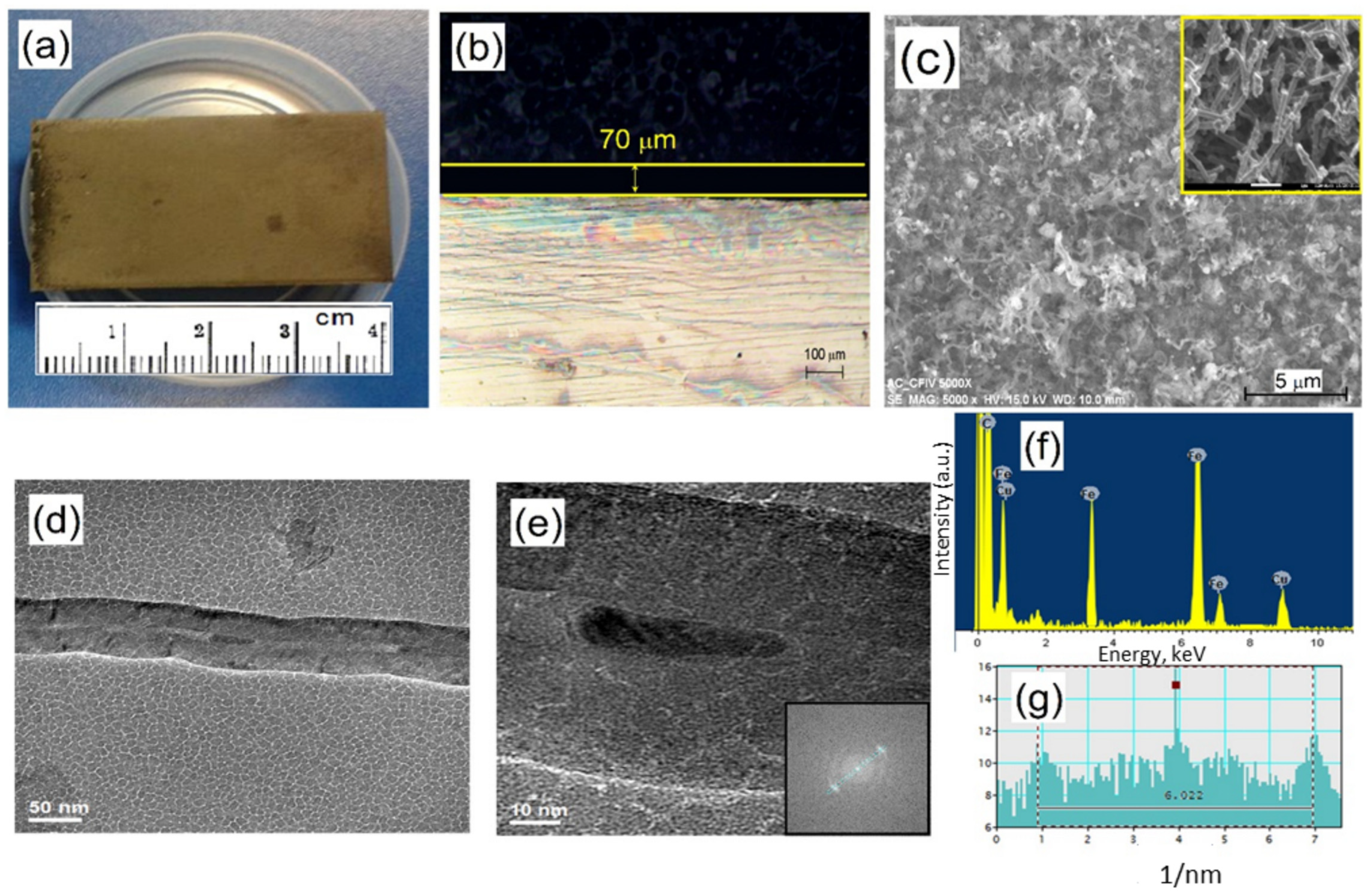
The morphology and structural characteristics of the carbon nanostructures (CNS) grown on AISI 1018 steel using the ferrocene/α-pinene precursor at 800 °C are presented in Figure 1.
Figure 1a shows an optical macrograph of the steel substrate, confirming the formation of a uniform, light-gray coating across the entire surface. Cross-sectional SEM analysis (Figure 1b) reveals a continuous film with a thickness of approximately 70 μm. High-magnification SEM imaging (Figure 1c and inset) illustrates a dense network of entangled tubular structures that are randomly oriented and distributed flat against the substrate. The length of these structures is in the 1–5 µm range.
Further structural analysis via HR-TEM (Figure 1d,e) confirms that these nanostructures are multiwalled carbon nanotubes (MWCNTs), with average inner and outer diameters of ~9 nm and ~60 nm, respectively. The Fast Fourier Transform (FFT) analysis (Figure 1e, inset) displays sharp diffraction spots, a hallmark of high crystallinity in carbonaceous materials. As shown in the line scan of the FFT (Figure 1g), the measured interlayer spacing (d002) is 0.332 nm. This value is in close agreement with the ideal interplanar distance of 0.335 nm for hexagonal graphite, particularly when compared to the large spacings (>0.34 nm) typically observed in turbostratic carbonaceous materials. The slight reduction in the measured spacing may suggest both a high degree of graphitization and the presence of internal compressive stresses within the concentric nanotube walls.
The EDS spectrum (Figure 1f) identifies iron particles within the MWCNT matrix, originating from the ferrocene catalyst. These metallic particles are encapsulated within the hollow cores or anchored to the external walls of the tubes. Consistent with previous literature [30], the iron species confined within the nanotube cavities typically exist as iron carbide (Fe3C). These findings suggest a growth mechanism wherein iron nanoparticles released from ferrocene act as catalytic sites for the assembly of carbon fragments derived from the thermal decomposition of α-pinene.
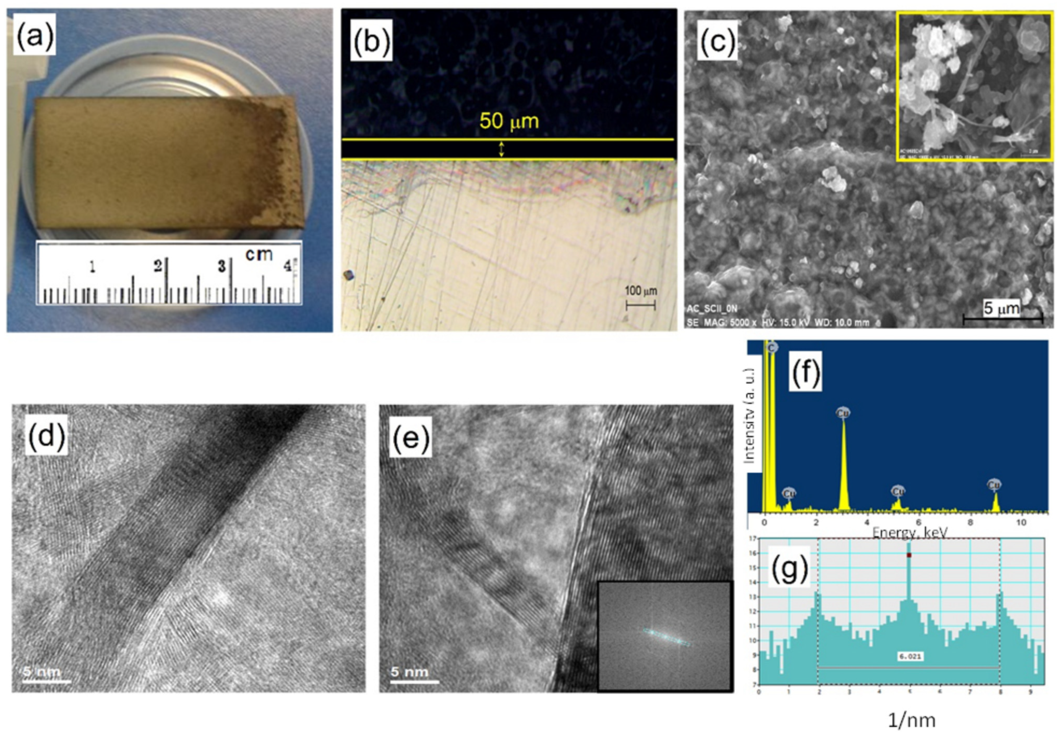
The morphological and structural evolution of CNS synthesized using pure α-pinene—without the addition of ferrocene—is illustrated in Figure 2.
Optical microscopy (Figure 2a) confirms that the AISI 1018 steel surface is predominantly covered by a uniform, light-gray film. Cross-sectional SEM analysis (Figure 2b) indicates a film thickness of approximately 50 μm, slightly thinner than the coatings produced with the ferrocene catalyst. High-magnification SEM imaging (Figure 2c) reveals an irregular network of interconnected tubular structures distributed across the substrate. The length of these structures is in the 1–2 µm range.
To further elucidate the nanostructure, HR-TEM analysis was performed on samples mechanically removed from the steel surface (Figure 2d,e). In contrast to the hollow nanotubes observed in the previous section, these structures appear as solid, continuous filaments without an internal cavity. Based on their morphology and lack of a central core, these are classified as ribbon-type CNFs [31], with diameters ranging from 5 to 25 nm.
The Fast Fourier Transform (FFT) analysis (Figure 2e, inset) displays distinct bright spots, confirming the crystalline nature of the nanofibers. The interplanar spacing, calculated from the FFT line scan (Figure 2g), was found to be 0.332 nm, consistent with the characteristic (002) lattice spacing of graphitic carbon. Notably, the EDS spectrum (Figure 2f) detected only carbon, with no signals corresponding to iron within the film.
These results demonstrate that CNFs can be directly synthesized on AISI 1018 steel without exogenous catalysts or surface pre-treatments. This suggests that the steel substrate undergoes in situ catalytic activation. It is hypothesized that hydrogen radicals released during the thermal decomposition of α-pinene create a reducing atmosphere at the surface. This process likely reduces surface iron oxides to metallic iron (Fe0) sites. The necessity of the steel substrate is further evidenced by the fact that CNF growth was observed solely on the AISI 1018 surfaces; the quartz reactor walls remained devoid of any carbonaceous structures under identical experimental conditions. This selective growth indicates that the steel does not merely act as a support but serves as an active catalytic participant, facilitating the transition from precursor decomposition to structured fiber growth.
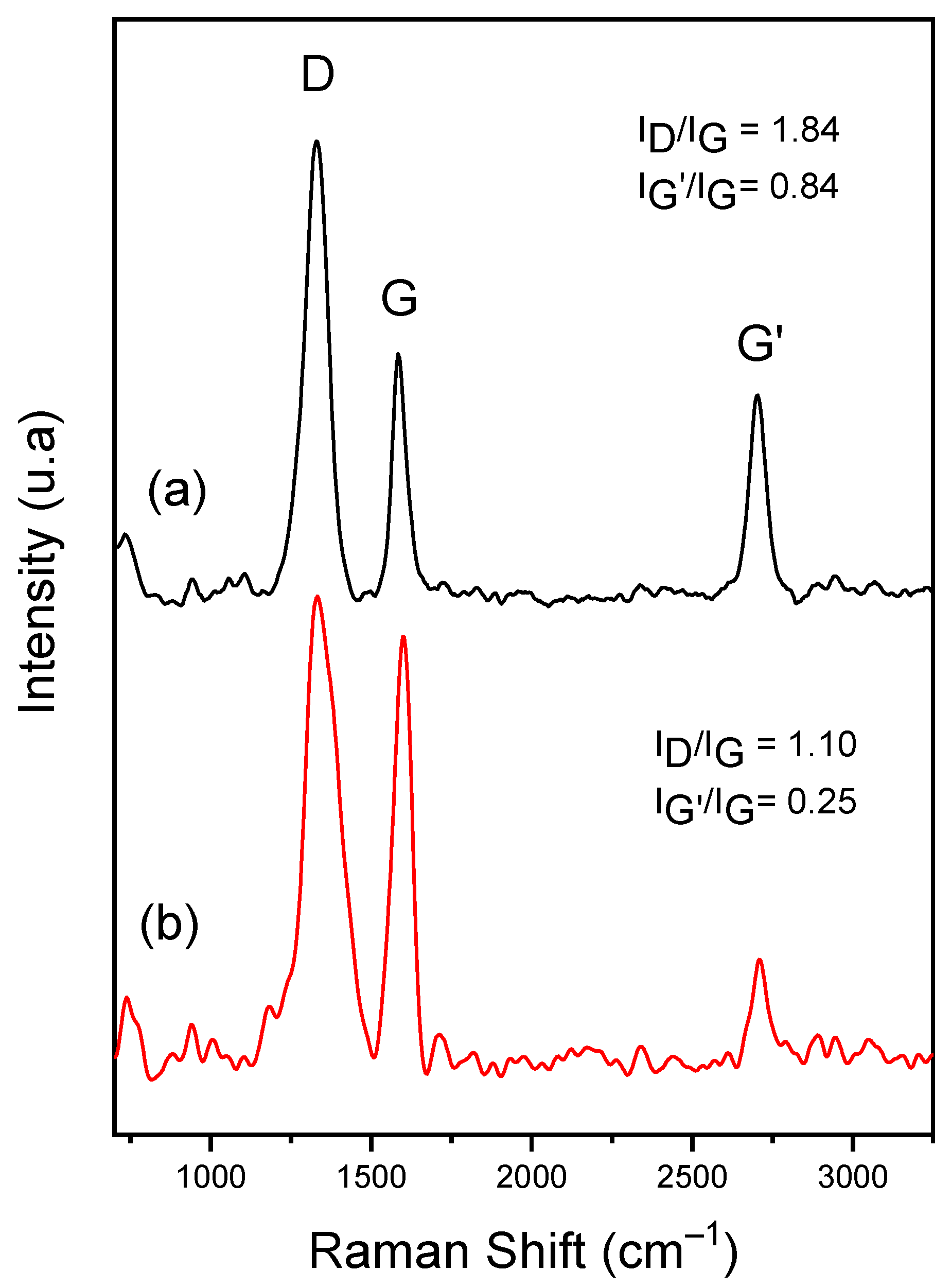
The vibrational properties and structural quality of the synthesized MWCNTs and CNFs were evaluated using Raman spectroscopy, as shown in Figure 3. Both spectra exhibit three fundamental peaks characteristic of graphitic carbon nanostructures: the D band (~1350 cm−1), associated with the A1g breathing mode. This disorder-induced band arises from structural defects, such as sp3-hybridized carbon atoms, vacancies, or edge effects in the graphitic lattice; the G band (~1580 cm−1), corresponding to the E2g stretching mode of sp2 carbon pairs. This peak indicates the degree of crystallinity and the presence of ordered graphitic planes and the G′ band (~2600 cm−1): Also referred to as the 2D band, this is the second-order overtone of the D band. It serves as an indicator of the long-range structural order and the stacking of graphene layers [31].
To quantify the structural integrity, the intensity ratios ID/IG and IG′/IG were calculated and are displayed alongside their respective spectra. The ID/IG ratio is widely used as a proxy for defect density, where a higher value signifies a more disordered structure. Conversely, the IG′/IG ratio provides insights into the degree of graphitization and long-range alignment [32].
The MWCNTs exhibited a higher ID/IG ratio compared to the CNFs, suggesting a higher concentration of structural defects. This increased disorder in the MWCNTs is likely attributed to the incorporation of iron and iron carbide particles from the ferrocene catalyst, which disrupt the continuity of the graphene shells. However, the MWCNTs also showed a higher IG′/IG ratio than the CNFs, indicating that despite the localized defects caused by the catalyst, the overall nanotubes maintain a higher degree of long-range crystallinity or alignment compared to the solid-ribbon nanofibers.

3.2. Tribological Performance of Carbon Nanostructures

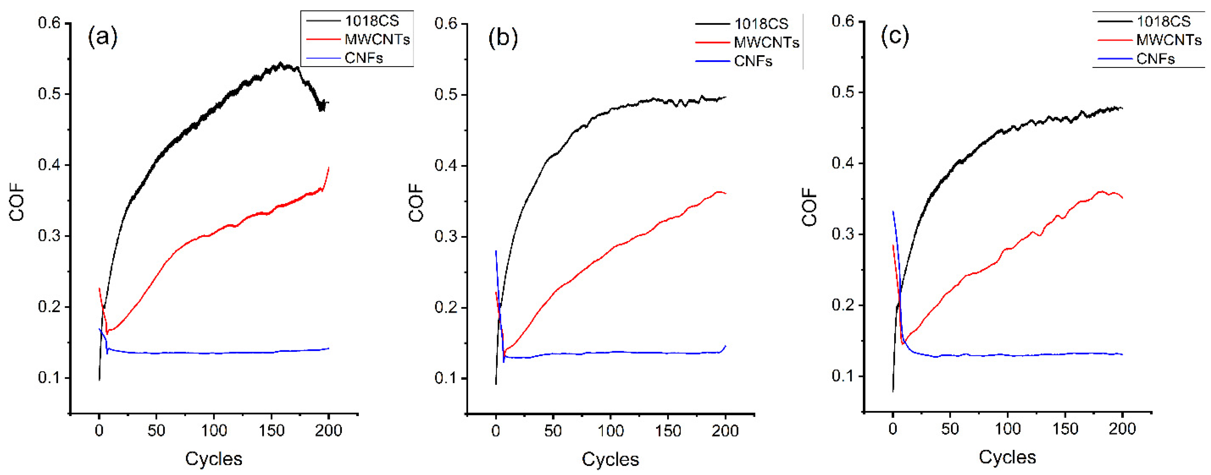
The tribological properties of the synthesized films and the bare AISI 1018 steel substrate were evaluated under dry contact conditions at normal loads of 2 N, 3 N, and 5 N. Figure 4 illustrates the friction coefficient (COF) as a function of the number of cycles for all samples.
At a 2 N load (Figure 4a), the bare steel substrate exhibited a rapid, linear increase in COF, reaching 0.35 within the first 25 cycles. This value continued to rise, peaking at 0.53 after 160 cycles before slightly stabilizing at 0.47 toward the end of the test. In contrast, the MWCNT-coated surface showed a gradual, linear increase in friction, reaching a COF of 0.36 by the end of the 200-cycle test. Most notably, the CNF-coated surface demonstrated superior lubrication, maintaining a consistently low and stable COF of ~0.12. This comparative trend remained consistent at higher loads of 3 N and 5 N (Figure 4b,c).
These results indicate that both CNS coatings (MWCNTs and CNFs) grown directly on AISI 1018 steel provide a significant reduction in friction compared to the uncoated substrate. The superior performance of the CNFs films over the MWCNT films can be attributed to several structural factors. As supported by previous studies on carbon nanorods [33,34], the degree of graphitization is a primary determinant of tribological efficacy. Higher crystallinity typically facilitates the easy shearing of graphitic planes, resulting in a lower COF. Our Raman and HR-TEM data confirm that CNFs possess higher structural order and fewer defects than MWCNTs. The presence of iron and iron carbide (Fe3C) nanoparticles within the MWCNTs likely detrimental to their performance. During sliding, these rigid particles may act as third-body abrasives, increasing the internal resistance and contributing to the higher observed COF. The solid “ribbon” morphology of the CNFs may offer better mechanical resilience under the high-contact-pressure conditions of the steel ball counterpart compared to the hollow MWCNTs.
The tribological tests were conducted in dry conditions at 2 N, 3 N and 5 N loads for 200 cycles and the results are shown in Figure 4 where the friction coefficient (COF) is plotted against the number of cycles. The bare AISI 1018 steel substrate as well as the carbonaceous films were tested at the same conditions of load and number of cycles. Figure 4a corresponds to the results obtained at 2 N load. At this load we observe that COF for the steel substrate increases linearly to reach a value of 0.35 during the first 25 cycles, continues to increase up to a value of 0.53 after 160 cycles and slightly decreases to a value of 0.47 for the remaining time of the test. This subtle reduction in the friction coefficient toward the end of the test is likely associated with the development of an oxidative wear regime. Under dry sliding, the contact interface undergoes localized heating, which can promote the formation of a compacted oxide ‘glaze’ layer. This layer can partially separate the sliding surfaces and reduce the shear strength of the contact, leading to the observed drop. Furthermore, the stabilization may be assisted by the removal of initial surface asperities during the running-in period, transitioning the contact from a severe wear state to a more stable sliding regime.
In the case of the MWCNT film, the COF increases linearly up to a value of 0.36 during the entire test. The COF recorded from the film consisting of CNFs showed the lowest COF value of ~0.12. The same trend is observed at 3 N and 5 N (Figure 4b,c).

3.3. Wear Track Analysis and Post-Test Characterization

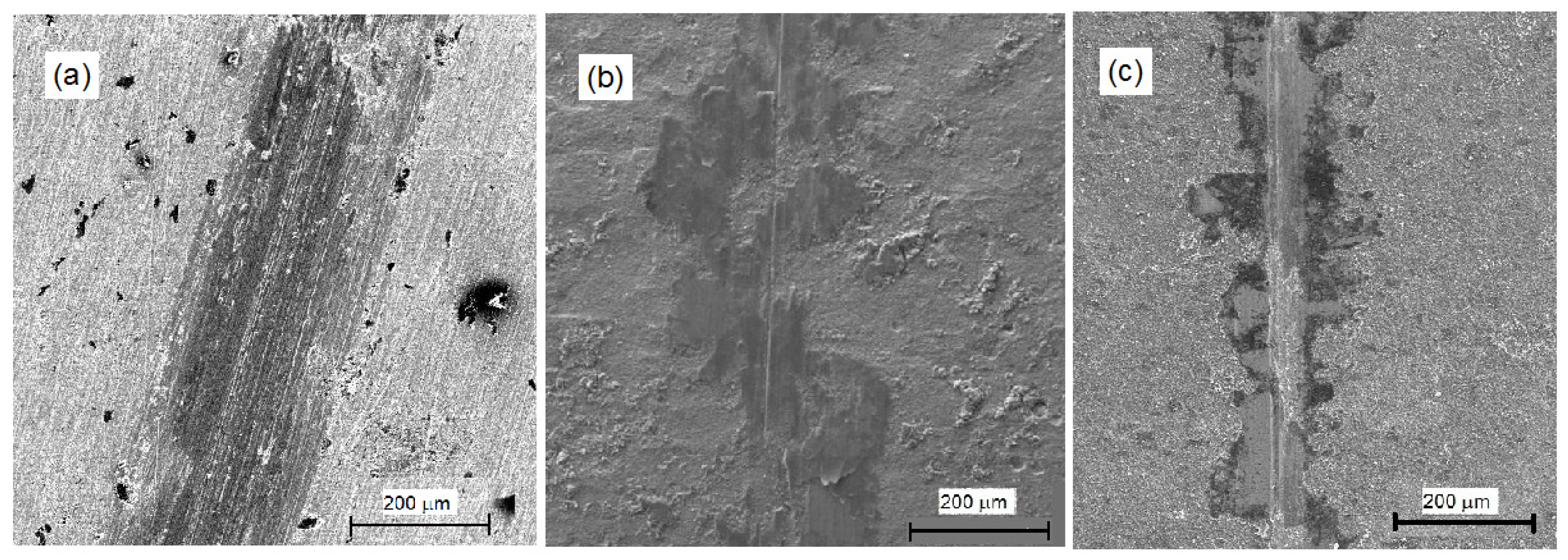
The morphology of the wear tracks generated at a 5 N load was examined via SEM to elucidate the lubrication mechanisms of the synthesized films (Figure 5).
The bare AISI 1018 steel surface (Figure 5a) exhibits prominent, parallel plowing grooves and significant plastic deformation, characteristic of a dominant adhesive wear mechanism. In contrast, these abrasive features are substantially mitigated on the MWCNT-coated (Figure 5b) and CNF-coated (Figure 5c) surfaces. In both CNS cases, the wear tracks are covered by compacted carbonaceous “build-up zones.” These layers act as protective solid lubricant films (tribofilms) that prevent direct metal-to-metal contact, thereby reducing the COF.
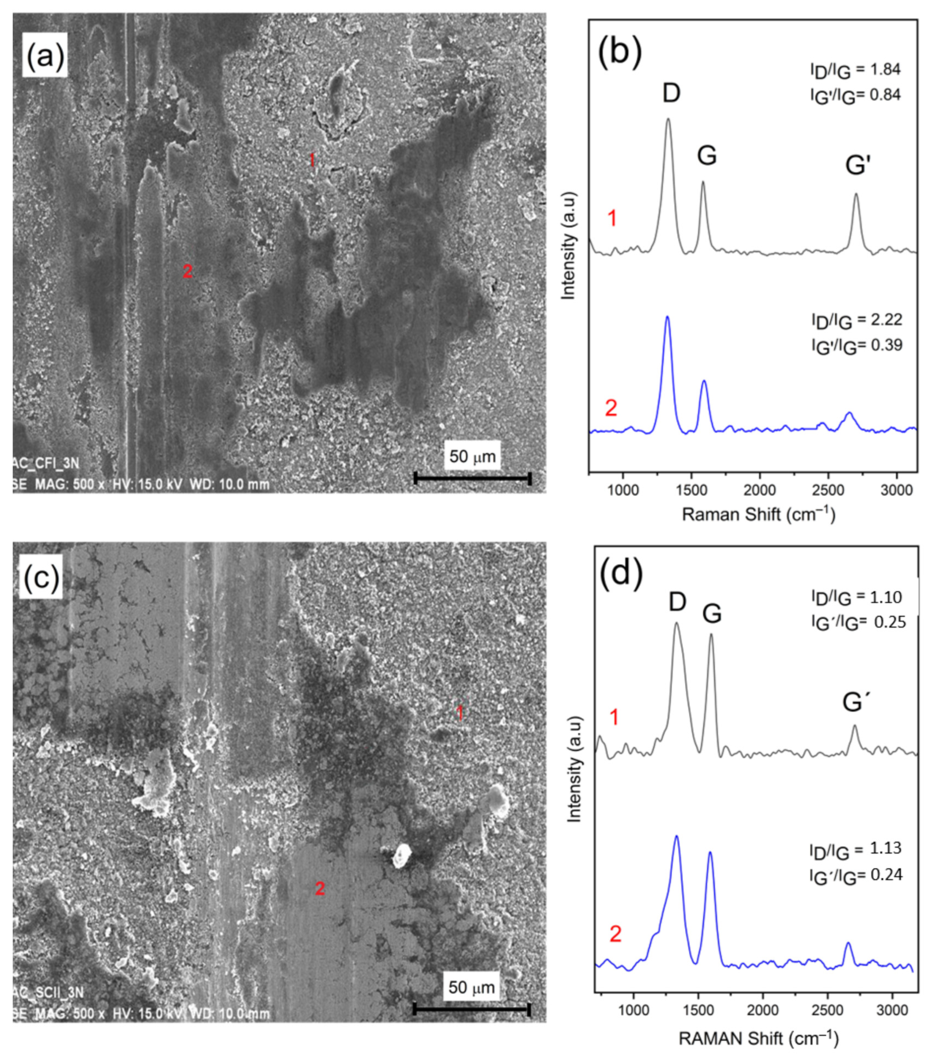
To evaluate the structural stability of the coatings under mechanical stress, high-magnification SEM imaging and micro-Raman spectroscopy were performed on the wear tracks (Figure 6). Two distinct morphological regions were identified in both the MWCNT (Figure 6a) and CNF (Figure 6c) samples:
  • Point 1 (Pristine Zone): Corresponds to the carbonaceous material outside the direct contact path, where the nanostructures remain in their as-synthesized state.
  • Point 2 (Deformed Zone): Corresponds to the center of the wear track, where the nanostructures have undergone significant flattening and compaction due to the repeated mechanical load and sliding action.
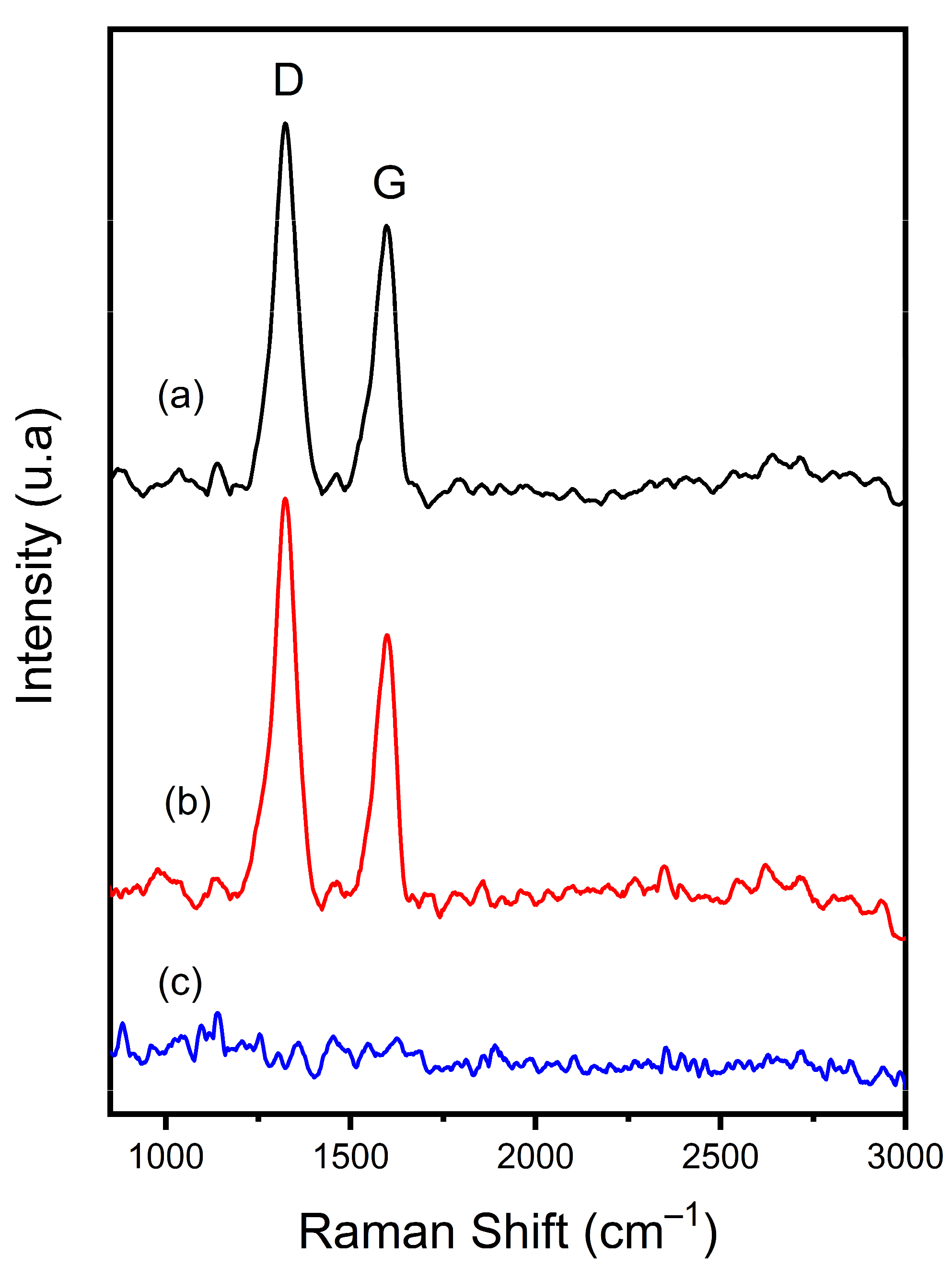
The Raman spectra acquired from these points provide insight into the damage accumulation within each film. To ensure statistical representativeness, five distinct regions were analyzed for each condition, and average ID/IG were calculated. For the MWCNT coatings (Figure 6b), a significant increase in the average ID/IG ratio is observed, rising from 1.84 ± 0.04 at Point 1 to 2.22 ± 0.06 at Point 2. This spectral change indicates that the nanotubes suffer from localized structural degradation and the accumulation of lattice defects during rubbing. This increasing defect density likely contributes to the rising friction coefficient observed in the tribological plots.
In contrast, the CNF coatings (Figure 6d) exhibit a remarkable resilience. The ID/IG and IG′/IG ratios at Point 2 remain nearly identical to those at Point 1. This suggests that the ribbon-type carbon nanofibers retain their crystalline integrity despite the high contact pressure. This structural robustness, combined with a lack of abrasive iron particles, explains the ability of CNFs to maintain a low-shear interface and a stable, low friction coefficient throughout the test duration.
To confirm the formation of a lubricating transfer film, the worn areas of the AISI 52100 steel balls were analyzed via Raman spectroscopy (Figure 7).
The Raman spectra collected from the contact area of the balls used against both MWCNT and CNF coatings exhibit the characteristic D, G, and G′ bands of graphitic carbon, mirroring the spectra of the wear tracks. This correlation confirms that the nanostructures are not merely displaced but are effectively sheared and adhered to the counterface ball. For the CNF samples, the consistency of the Raman signal across the wear scar suggests the formation of a coherent and uniform tribofilm. This is mechanically supported by the friction results in Figure 4; the lack of significant COF fluctuations implies that this transfer layer successfully prevents direct metal-to-metal contact between the AISI 52100 ball and the steel substrate. In contrast, the bare steel tests (Figure 7c) show only base metal signals, confirming that the reduction in friction is a direct consequence of this stable, carbon-rich interface.
In contrast, the Raman analysis of the ball used against the bare AISI 1018 steel (Figure 7c) showed no carbon-related signals, confirming that the lubricating layer is exclusively derived from the synthesized nanostructures. The presence of this persistent transfer film in the CNS-coated samples—particularly the crystalline film observed in the case of CNFs—is the primary mechanism responsible for the significant reduction in the friction coefficient and the protection of the underlying steel surfaces. The disappearance of the 2D peak at 2700 cm−1 in the transferred film (Figure 7) suggests a transition from highly ordered carbon nanostructures to a more disordered, sheared tribofilm, consistent with the mechanical degradation of the MWCNTs/CNFs under high contact pressure.
The optimization of synthesis duration is a critical factor in determining the tribological efficacy of the grown CNS. Our results suggest that the length and density of the MWCNTs and CNFs—governed by the growth time—directly influence the friction and wear mechanisms. At shorter synthesis durations, the carbon nanostructure coverage may be insufficient to fully shield the AISI 1018 substrate, leading to higher friction due to partial metal-to-metal contact. Conversely, an excessive growth period can lead to highly entangled, elongated structures that are susceptible to delamination under high shear stress. The optimal synthesis duration provides a ‘sweet spot’ where the CNS are sufficiently long to form a stable, continuous graphitic tribofilm while maintaining strong interfacial adhesion to the steel substrate. This balance minimizes the coefficient of friction (COF) by facilitating a rolling-to-sliding lubrication transition and preventing the accumulation of abrasive carbon debris.

4. Conclusions

CNS were successfully synthesized on AISI 1018 low-carbon steel substrates using α-pinene as a sustainable, biorenewable carbon source via spray pyrolysis. The study demonstrated that the choice of catalyst configuration fundamentally dictates the resulting nanostructure:
  • Catalyst-Aided Route: The addition of ferrocene led to the formation of MWCNTs with a film thickness of ~70 μm.
  • Catalyst-Free Route: The use of pure α-pinene enabled the direct growth of ribbon-type CNFs with a thickness of ~50 μm, effectively utilizing the steel substrate as an in situ catalyst.
HR-TEM and Raman spectroscopy revealed that the CNFs exhibited superior crystallinity and lower defect density compared to the MWCNTs. While both coatings significantly improved the tribological properties of the steel, the CNFs demonstrated a superior lubrication performance. Specifically, the CNFs maintained a stable friction coefficient of ~0.12 at lower loads (2–3 N), with a slight increase to ~0.18 under a 5 N load, significantly outperforming the MWCNTs (0.15–0.35) under identical conditions. The enhanced performance of the CNF coatings is attributed to their high structural integrity and the absence of abrasive iron carbide inclusions. Post-test characterization confirmed the formation of a robust, highly crystalline graphitic transfer film on the counterpart surface, which remains effective across the tested load range despite the moderate friction increase observed at the 5 N limit. This stable interface facilitates low interfacial shear strength, providing effective surface protection and a superior lubrication mechanism compared to conventional petroleum-derived carbon coatings.

Author Contributions

Conceptualization, R.S.-M., J.L.-R. (Javier Lara-Romero) and F.C.-C.; Methodology, A.P.G.y.M., R.S.-M., J.L.-R. (Javier Lara-Romero), R.R.S., J.L.-R. (José Lemus-Ruiz) and O.J.-A.; Validation, A.P.G.y.M., R.S.-M., J.L.-R. (José Lemus-Ruiz), O.J.-A. and F.C.-C.; Formal analysis, A.P.G.y.M., J.L.-R. (Javier Lara-Romero), R.R.S. and F.C.-C.; Investigation, R.S.-M. and J.L.-R. (José Lemus-Ruiz); Data curation, O.J.-A.; Writing—original draft, A.P.G.y.M., R.S.-M., J.L.-R. (Javier Lara-Romero), R.R.S., J.L.-R. (José Lemus-Ruiz), O.J.-A. and F.C.-C.; Writing—review and editing, J.L.-R. (Javier Lara-Romero); Visualization, J.L.-R. (Javier Lara-Romero) and R.R.S.; Supervision, J.L.-R. (Javier Lara-Romero); Project administration, J.L.-R. (Javier Lara-Romero); Funding acquisition, J.L.-R. (Javier Lara-Romero). All authors have read and agreed to the published version of the manuscript.

Funding

Ministry of Sciences, Humanities, Technology and Innovation (CONACyT—Proyecto Ciencia Básica 241536).

Data Availability Statement

The original contributions presented in this study are included in the article. Further inquiries can be directed to the corresponding autor.

Acknowledgments

This work was supported by the Mexican National Council for Science and Technology (CONACyT) through Basic Science Project No. 241536. The authors gratefully acknowledge this financial assistance.

Conflicts of Interest

The authors declare no conflict of interest.

References

  1. Wang, Y.; Li, D.; Sun, W.; Sun, J.; Li, G.; Zhang, H.; Cheng, Y. Synthesis and field electron emission properties of multi-walled carbon nanotube films directly grown on catalytic stainless steel substrate. Vacuum 2018, 149, 195–199. [Google Scholar] [CrossRef]
  2. Zhang, Y.; Klittich, M.R.; Gao, M.; Dhinojwala, A. Delaying frost formation by controlling surface chemistry of carbon nanotube-coated steel surfaces. ACS Appl. Mater. Interfaces 2017, 9, 6512–6519. [Google Scholar] [CrossRef] [PubMed]
  3. Si, Y.; Sun, C.; Li, D.; Yang, F.; Tang, C.Y.; Quan, X.; Guiver, M.D. Flexible Superhydrophobic Metal-based Carbon Nanotube Membrane for Electrochemically Enhanced Water Treatment. Environ. Sci. Technol. 2020, 54, 9074–9082. [Google Scholar] [CrossRef] [PubMed]
  4. Shi, X.; Li, Y.; Chen, R.; Ni, H.; Zhan, W.; Zhang, B.; Dong, S. Defective carbon nanotube forest grown on stainless steel encapsulated in MnO2 nanosheets for supercapacitors. Electrochim. Acta. 2018, 278, 61–71. [Google Scholar] [CrossRef]
  5. Chen, X.H.; Chen, C.S.; Xiao, H.N.; Cheng, F.Q.; Zhang, G.; Yi, G.J. Corrosion behavior of carbon nanotubes–Ni composite coating. Surf. Coat. Int. 2005, 191, 351–356. [Google Scholar] [CrossRef]
  6. Lee, C.H.; Johnson, N.; Drelich, J.; Yap, Y.K. The performance of superhydrophobic and superoleophilic carbon nanotube meshes in water–oil filtration. Carbon 2011, 49, 669–676. [Google Scholar] [CrossRef]
  7. Nunes, W.G.; Vicentini, R.; Da Silva, L.M.; Costa, L.H.; Tadeu, T.; Zanin, H. Surface and electrochemical properties of radially oriented multiwalled carbon nanotubes grown on stainless steel mesh. J. Electrochem. Soc. 2018, 165, A3684. [Google Scholar] [CrossRef]
  8. Suárez-Martínez, R.; Ocampo-Macias, T.; Lara-Romero, J.; Lemus-Ruiz, J.; Jiménez-Alemán, O.; Chinas-Castillo, F.; Paraguay-Delgado, F. Synthesis and tribological Performance of carbon nanostructures formed on AISI 316 stainless steel substrates. Tribol. Lett. 2016, 64, 36. [Google Scholar] [CrossRef]
  9. Camilli, L.; Scarselli, M.; Del Gobbo, S.; Castrucci, P.; Nanni, F.; Gautron, E.; Lefrant, S.; De Crescenzi, M. The synthesis and characterization of carbon nanotubes grown by chemical vapor deposition using a stainless steel catalyst. Carbon 2011, 49, 3307–3315. [Google Scholar] [CrossRef]
  10. Ionescu, M.I.; Zhang, Y.; Li, R.; Sun, X.; Abou-Rachid, H.; Lussier, L.-S. Hydrogen-free spray pyrolysis chemical vapor deposition method for the carbon nanotube growth: Parametric studies. Appl. Surf. Sci. 2011, 257, 6843–6849. [Google Scholar] [CrossRef]
  11. Kim, B.; Chung, H.; Chu, K.S.; Yoon, H.G.; Lee, C.J.; Kim, W. Synthesis of vertically-aligned carbon nanotubes on stainless steel by water-assisted chemical vapor deposition and characterization of their electrochemical properties. Synth. Met. 2010, 160, 584–587. [Google Scholar] [CrossRef]
  12. Hashempour, M.; Vicenzo, A.; Zhao, F.; Bestetti, M. Direct growth of MWCNTs on 316 stainless steel by chemical vapor deposition: Effect of surface nano-features on CNT growth and structure. Carbon 2013, 63, 330–347. [Google Scholar] [CrossRef]
  13. Hordy, N.; Mendoza-Gonzalez, N.-Y.; Coulombe, S.; Meunier, J.-L. The effect of carbon input on the morphology and attachment of carbon nanotubes grown directly from stainless steel. Carbon 2013, 63, 348–357. [Google Scholar] [CrossRef]
  14. Romero, P.; Oro, R.; Campos, M.; Torralba, J.M.; de Villoria, R.G. Simultaneous synthesis of vertically aligned carbon nanotubes and amorphous carbon thin films on stainless steel. Carbon 2015, 82, 31–38. [Google Scholar] [CrossRef]
  15. Masarapu, C.; Wei, B. Direct growth of aligned multiwalled carbon nanotubes on treated stainless steel substrates. Langmuir 2007, 23, 9046–9049. [Google Scholar] [CrossRef] [PubMed]
  16. Vander Wal, R.L.; Hall, L.J. Carbon nanotube synthesis upon stainless steel meshes. Carbon 2003, 41, 659–672. [Google Scholar] [CrossRef]
  17. Reinert, L.; Suárez, S.; Rosenkranz, A. Tribo-Mechanisms of Carbon Nanotubes: Friction and Wear Behavior of CNT-Reinforced Nickel Matrix Composites and CNT-Coated Bulk Nickel. Lubricants 2016, 4, 11. [Google Scholar] [CrossRef]
  18. Baddour, C.E.; Fadlallah, F.; Nasuhoglu, D.; Mitra, R.; Vandsburger, L.; Meunier, J.L. A simple thermal CVD method for carbon nanotube synthesis on stainless steel 304 without the addition of an external catalyst. Carbon 2009, 47, 313–318. [Google Scholar] [CrossRef]
  19. Schäfer, C.; Reinert, L.; MacLucas, T.; Grützmacher, P.; Merz, T.; Mücklich, F.; Suarez, S. Influence of Surface Design on the Solid Lubricity of Carbon Nanotubes-Coated Steel Surfaces. Tribol. Lett. 2018, 66, 89. [Google Scholar] [CrossRef]
  20. Salvetat, J.-P.; Bonard, J.-M.; Thomson, N.; Kulik, A.; Forro, L.; Benoit, W.; Zuppiroli, L. Mechanical properties of carbon nanotubes. Appl. Phys. A 1999, 69, 255–260. [Google Scholar] [CrossRef]
  21. Joly-Pottuz, L.; Dassenoy, F.; Vacher, B.; Martin, J.M.; Mieno, T. Ultralow friction and wear behaviour of Ni/Y-based single wall carbon nanotubes (SWNTs). Tribol. Int. 2004, 37, 1013–1018. [Google Scholar] [CrossRef]
  22. Peng, Y.; Hu, Y.; Wang, H. Tribological behaviors of surfactant-functionalized carbon nanotubes as lubricant additive in water. Tribol. Lett. 2007, 25, 247–253. [Google Scholar] [CrossRef]
  23. Wang, B.; Wang, X.; Lou, W.; Hao, J. Rheological and tribological properties of ionic liquid-based nanofluids containing functionalized multi-walled carbon nanotubes. J. Phys. Chem. C 2010, 114, 8749–8754. [Google Scholar] [CrossRef]
  24. Cui, L.-J.; Geng, H.-Z.; Wang, W.-Y.; Chen, L.-T.; Gao, J. Functionalization of multi-wall carbon nanotubes to reduce the coefficient of the friction and improve the wear resistance of multi-wall carbon nanotube/epoxy composites. Carbon 2013, 54, 277–282. [Google Scholar] [CrossRef]
  25. Arai, S.; Fujimori, A.; Murai, M.; Endo, M. Excellent solid lubrication of electrodeposited nickel-multiwalled carbon nanotube composite films. Mater. Lett. 2008, 62, 3545–3548. [Google Scholar] [CrossRef]
  26. Dickrell, P.; Sinnott, S.; Hahn, D.; Raravikar, N.; Schadler, L.; Ajayan, P.; Sawyer, W. Frictional anisotropy of oriented carbon nanotube surfaces. Tribol. Lett. 2005, 18, 59–62. [Google Scholar] [CrossRef]
  27. Kinoshita, H.; Kume, I.; Tagawa, M.; Ohmae, N. High friction of a vertically aligned carbon-nanotube film in microtribology. Appl. Phys. Lett. 2004, 85, 2780–2781. [Google Scholar] [CrossRef]
  28. Hu, J.; Jo, S.; Ren, Z.; Voevodin, A.; Zabinski, J. Tribological behavior and graphitization of carbon nanotubes grown on 440C stainless steel. Tribol. Lett. 2005, 19, 119–125. [Google Scholar] [CrossRef]
  29. Abad, M.; Sánchez-López, J.C.; Berenguer-Murcia, A.; Golovko, V.; Cantoro, M.; Wheatley, A.; Fernández, A.; Johnson, B.; Robertson, J. Catalytic growth of carbon nanotubes on stainless steel: Characterization and frictional properties. Diam. Relat. Mater. 2008, 17, 1853–1857. [Google Scholar] [CrossRef]
  30. Lara-Romero, J.; Alonso-Núñez, G.; Jiménez-Sandoval, S.; Avalos-Borja, M. Growth of Multi-Walled Carbon Nanotubes by Nebulized Spray Pyrolysis of a Natural Precursor: Alpha-Pinene. J. Nanosci. Nanotechnol. 2008, 8, 6509–6512. [Google Scholar] [CrossRef]
  31. Dresselhaus, M.S.; Dresselhaus, G.; Saito, R.; Jorio, A. Raman spectroscopy of carbon nanotubes. Phys. Rep. 2005, 409, 47–99. [Google Scholar] [CrossRef]
  32. Donato, M.; Galvagno, S.; Messina, G.; Milone, C.; Pistone, A.; Santangelo, S. Optimisation of gas mixture composition for the preparation of high quality MWCNT by catalytically assisted CVD. Diam. Relat. Mater. 2007, 16, 1095–1100. [Google Scholar] [CrossRef]
  33. Tu, J.; Jv, Y.; Xia, Z.; Guo, S. Friction Properties of Array Films of Amorphous Carbon Nanorods Prepared by Dual-Catalyst Growth on Porous AAO Membrane. In World Tribology Congress III; American Society of Mechanical Engineers: New York, NY, USA, 2005; Volume 2, pp. 353–354. [Google Scholar] [CrossRef]
  34. Tu, J.; Jiang, C.; Guo, S.; Zhao, X.; Fu, M. Tribological properties of aligned film of amorphous carbon nanorods on AAO membrane in different environments. Wear 2005, 259, 759–764. [Google Scholar] [CrossRef]
Figure 1. Morphological and structural characterization of MWCNTs synthesized on AISI 1018 steel using a ferrocene/α-pinene precursor at 800 °C for 2 h. (a) Optical macrograph showing the uniform CNS coating. (b) Cross-sectional SEM micrograph indicating a film thickness of ~70 μm. (c) High-magnification top-view SEM image revealing the entangled nanotube network. (d) HR-TEM micrograph of the multiwalled structure. (e) Lattice-resolved HR-TEM image with corresponding FFT (inset) demonstrating high crystallinity. (f) EDS spectrum identifying the elemental composition and iron-based catalytic inclusions. (g) Line scan analysis derived from the FFT showing an interlayer spacing of 0.332 nm.
Nanomanufacturing 06 00020 g001
Figure 2. Characterization of ribbon-type CNFs synthesized on AISI 1018 steel via catalyst-free pyrolysis of pure α-pinene at 800 °C for 120 min. (a) Optical macrograph of the steel substrate showing the predominantly gray CNF coating. (b) Cross-sectional SEM micrograph indicating a film thickness of ~50 μm. (c) Top-view SEM image illustrating the irregular network of nanofibers. (d) HR-TEM image confirming the solid “ribbon” morphology of the fibers. (e) High-magnification HR-TEM image with corresponding FFT (inset) highlighting the crystalline lattice. (f) EDS spectrum showing a high-purity carbon signal with no detectable iron catalyst. (g) Line scan analysis of the FFT confirming an interlayer graphitic distance of 0.332 nm.
Nanomanufacturing 06 00020 g002
Figure 3. Raman spectra of the synthesized carbon nanostructures: (a) MWCNTs grown with ferrocene and (b) CNFs grown via the catalyst-free method. The characteristic D, G, and G′ bands are labeled, along with their respective ID/IG and IG′/IG intensity ratios used for structural quality assessment.
Nanomanufacturing 06 00020 g003
Figure 4. Comparative evolution of the friction coefficient (COF) as a function of sliding cycles for bare AISI 1018 steel, MWCNT-coated steel, and CNF-coated steel. Tests were conducted in dry contact conditions for 200 cycles at applied normal loads of (a) 2 N, (b) 3 N, and (c) 5 N.
Nanomanufacturing 06 00020 g004
Figure 5. SEM micrographs of the wear tracks generated after 200 sliding cycles at a 5 N load for: (a) bare AISI 1018 steel, (b) MWCNT-coated steel, and (c) CNF-coated steel. The bare steel exhibits severe plowing and adhesive wear, while the CNS-coated surfaces show the formation of protective carbonaceous tribofilms that mitigate surface damage.
Nanomanufacturing 06 00020 g005
Figure 6. Correlative SEM and Raman analysis of the wear tracks after 200 sliding cycles at a 5 N load. (a,b) High-magnification SEM micrograph and corresponding Raman spectra for the MWCNT-coated surface. (c,d) High-magnification SEM micrograph and corresponding Raman spectra for the CNF-coated surface. In both cases, Point 1 indicates the pristine as-synthesized material, while Point 2 denotes the compacted tribofilm within the wear track. The stable ID/IG ratios in (d) highlight the superior structural resilience of the CNFs compared to the degradation observed in the MWCNTs (b).
Nanomanufacturing 06 00020 g006
Figure 7. Raman spectra obtained from the wear scars of the AISI 52100 steel ball counterparts after 200 sliding cycles at a 5 N load. Spectra correspond to the balls tested against (a) MWCNT coatings, (b) CNF coatings, and (c) bare AISI 1018 steel. The prominent graphitic bands in (a,b) indicate the successful formation of a carbonaceous transfer film on the counterpart surface, while the absence of signals in (c) confirms the lack of lubrication on the bare steel.
Nanomanufacturing 06 00020 g007
Disclaimer/Publisher’s Note: The statements, opinions and data contained in all publications are solely those of the individual author(s) and contributor(s) and not of MDPI and/or the editor(s). MDPI and/or the editor(s) disclaim responsibility for any injury to people or property resulting from any ideas, methods, instructions or products referred to in the content.