Article

A Severity Threshold for Frictional Stability in ZrB2SiC/ZrO2 Coatings: Implications for Tool Life in Titanium Machining


by
Willian Aperador
1,*,
Giovany Orozco-Hernández
2 and
Julio Cesar Caicedo
3
1
Department of Engineering, Universidad Militar Nueva Granada, Bogota 110111, Colombia
2
Postgraduate Department, Universidad ECCI, Bogota 111311, Colombia
3
Tribology, Polymers, Powder Metallurgy and Solid Waste Transformations Research Group, Universidad del Valle, Cali 760001, Colombia
*
Author to whom correspondence should be addressed.
Solids 2026, 7(4), 39; https://doi.org/10.3390/solids7040039
Submission received: 9 July 2026 / Revised: 10 August 2026 / Accepted: 12 August 2026 / Published: 17 August 2026
(This article belongs to the Topic Multi-scale Modeling and Optimisation of Materials)

Abstract

Ultra-high-temperature ceramic (UHTC) coatings offer a promising route to extending cutting tool service life under severe conditions. This work evaluates the tribological behaviour and wear regime transitions of ZrB2–SiC/ZrO2 coatings, deposited by physical vapour deposition (PVD) onto ASSAB-17 high-speed steel tool bits, during dry turning of Ti-6Al-4V. Structural, microstructural, mechanical, and tribological characterisation was performed by X-ray diffraction (XRD), scanning electron microscopy (SEM), nanoindentation, and pin-on-disc testing under three pressure–velocity (PV) severity levels, with worn surfaces analysed by SEM and profilometry. The coating exhibited a nanostructured ZrB2/β-SiC/t-ZrO2 architecture with a hardness (H) of 24 ± 3 GPa, a hardness-to-reduced-elastic-modulus ratio (H/Er) of 0.100, and an elastic resistance to plastic deformation (H3/Er2) of 0.240 GPa. Three tribological regimes were identified: running-in, steady-state sliding, and progressive degradation, with the highest severity (PV = 6.0 N·m/s) triggering degradation beyond approximately 620 m, a more than one-order-of-magnitude rise in wear rate, and the only case exceeding the tool-life criterion of maximum flank wear (VBmax = 0.30 mm) according to ISO 3685. The main advantage of the proposed approach is that it condenses tool-life-relevant behaviour into a single, easily measurable severity parameter, the PV product, directly applicable to coating design and the selection of safe machining-condition windows. The overall behaviour is consistent with a mechanism governed by the stability and regeneration capacity of a protective tribofilm. As the composition of this layer was not directly characterised, this mechanism is proposed as a phenomenological interpretation, from which a PV threshold is derived as a design criterion for UHTC coatings.

1. Introduction

Tool wear during machining operations constitutes one of the principal tribological challenges in modern manufacturing, owing to its direct impact on dimensional accuracy, surface quality, productivity and production costs. Extreme contact conditions develop at the tool–workpiece interface, characterised by normal pressures on the order of 1–3 GPa, instantaneous temperatures exceeding 800 °C, and strain rates between 103 and 105 s−1, under which plastic deformation, frictional heating and tribochemical reactions occur simultaneously. Consequently, tool wear ceases to be an exclusively mechanical phenomenon and instead becomes governed by the interaction of mechanical, thermal and chemical processes that evolve continuously throughout machining [1,2,3,4].
Titanium alloys, particularly Ti-6Al-4V, are widely employed in the aerospace, biomedical and energy sectors owing to their high strength-to-weight ratio, excellent corrosion resistance and outstanding fatigue behaviour [5]. However, their low thermal conductivity (λ ≈ 7 W m−1 K−1), high chemical affinity with most tool materials, and marked strain hardening tendency render this alloy one of the most difficult materials to machine [6,7]. These characteristics promote the concentration of thermal and mechanical stresses at the cutting edge, accelerate wear processes, and favour adhesive, oxidative and diffusive phenomena. Among these, the formation of built-up edge (BUE) is particularly significant, as it modifies the effective tool geometry, alters contact conditions, and accelerates the transition towards more severe wear mechanisms [8].
In this context, advanced ceramic coatings have become established as one of the most effective strategies for extending cutting tool service life, acting as thermal, chemical and mechanical barriers against extreme contact conditions. Among these, ultra-high-temperature ceramics (UHTCs) stand out for retaining their structural stability and mechanical properties even under high-temperature and high-load conditions. In particular, ZrB2-based systems exhibit hardness values exceeding 20 GPa, melting points above 3000 °C, and excellent oxidation resistance [9,10,11,12]. The incorporation of SiC promotes microstructural refinement, increases fracture toughness, and favours the formation of protective silica-rich phases during tribological contact [13,14]. Meanwhile, the presence of ZrO2, whether incorporated as a constituent phase or generated in situ during service, provides transformation-toughening mechanisms and stress redistribution capacity that enhance cracking resistance and improve the mechanical stability of the coating under cyclic loading conditions [15,16].
Despite the progress achieved in the development of UHTC coatings, most investigations have focused on structural characterisation and on the quantification of mechanical or tribological properties under simplified laboratory conditions. By contrast, few studies have addressed, in an integrated manner, the relationship between coating microstructure, the tribochemical reactions developed during contact, tribofilm evolution, and the transition between different wear mechanisms during actual machining operations on titanium alloys [17,18]. Likewise, it is not yet fully understood how the composition, continuity and mechanical stability of tribofilms regulate friction and control the transition between moderate and severe wear in multiphase ZrB2SiC/ZrO2 systems [19,20].
In bulk ZrB2–SiC ceramics, tribofilm formation during sliding has been associated with the oxidation products generated at the contact interface: the oxidation of ZrB2 yields ZrO2 and B2O3, with the latter acting as a low-shear strength phase at moderate temperatures, whereas the oxidation of SiC supplies SiO2 that can combine with B2O3 to form borosilicate-type glassy layers of higher thermal stability [13,14,18,19]. High-temperature sliding studies on ceramics [18] and on ZrB2–SiC composites [19], together with recent work on related carbide and MAX phase systems [20,21], indicate that the friction and wear response of these materials is largely governed by the continuity and load-bearing capacity of such oxide-based layers, whose formation depends strongly on contact load, sliding velocity and temperature. It should be noted, however, that this evidence derives mostly from bulk composites tested under controlled conditions and that its chemical verification has required surface-sensitive techniques such as XPS, Raman spectroscopy or TEM; equivalent information for PVD ZrB2SiC/ZrO2 coatings under machining-relevant contact conditions is still scarce.
When the most closely related studies are examined individually, the limitations that define the present research gap become apparent. Yang et al. [18] demonstrated tribofilm formation on ceramics during high-temperature sliding, but their work concerned bulk monolithic materials under furnace-controlled temperatures, not coatings under machining-representative contact severities. Gupta and Kumar [19] analysed the sliding wear of bulk ZrB2–SiC composites and established the influence of SiC content and counterbody selection, yet without addressing thin film architectures or defining any severity limit for the stability of the protective layers. Prakasarao et al. [20] reported the high-temperature sliding wear resistance of SiC–ZrN composites, again for bulk materials and without validation under machining conditions. Munir et al. [21] identified load-driven tribofilm formation and a friction–wear trade-off in Ti2AlN- and Ti2NTx-based coatings, but for a chemically different (non-boride) system and without any connection to standardised tool life criteria. Finally, Xu et al. [17] improved the adhesion and wear resistance of AlCrN coatings for titanium alloy applications through laser shock peening of the substrate, without considering UHTC compositions or the stability of the protective layer as a design variable. Taken together, none of these studies establishes, for a PVD UHTC coating, a quantitative contact severity limit linking frictional stability to a standardised tool life criterion. Such a limit is precisely what industry requires: dry machining of Ti-6Al-4V is increasingly demanded for economic and environmental reasons, and tool replacement and process window decisions in production rely on measurable criteria such as ISO 3685 [22] rather than on qualitative descriptions of wear mechanisms.
Although several studies have shown that tribofilms can significantly reduce friction and wear [21], understanding of the mechanisms governing their nucleation, growth, mechanical stability and degradation under severe contact conditions remains limited. In particular, for PVD ZrB2SiC/ZrO2 coatings, it has not been established under which contact severity conditions a stable protective layer can be sustained, nor how the loss of frictional stability relates to the transition between moderate and severe wear during the machining of Ti-6Al-4V. Accordingly, the novelty of the present work does not lie in the direct chemical identification of the tribofilm, but in establishing, through the systematic variation in the pressure–velocity (PV) product and its comparison with real machining conditions, a severity threshold that links frictional stability, the transition in specific wear rate and tool life for this coating system. This limitation hinders the establishment of design criteria for coatings capable of maintaining stable tribological behaviour under extreme operating conditions.
With the aim of contributing to the understanding of these phenomena, the present work evaluates the tribological behaviour of ZrB2SiC/ZrO2 coatings deposited by physical vapour deposition (PVD) onto ASSAB-17 high-speed steel tool bits used in the dry turning of Ti-6Al-4V alloy. Through the combination of structural (XRD), microstructural (SEM), mechanical (nanoindentation) and tribological (pin-on-disc testing) characterisation techniques, the relationship between coating architecture, the evolution of the coefficient of friction, and tribofilm formation is analysed under different levels of tribological severity. Finally, a phenomenological model, built on frictional, wear rate and morphological evidence, is proposed to describe how the formation, stabilisation and progressive degradation of a protective surface layer may control the transition between moderate and severe wear regimes during sliding contact, providing design and optimisation criteria for UHTC coatings intended for the machining of titanium alloys. Because the experimental programme did not include surface-sensitive chemical analyses of the contact interface, this model is presented as an interpretative framework to be verified in future work rather than as a directly demonstrated mechanism.
The results show that the coating developed a three-phase nanostructured architecture (ZrB2, β-SiC and t-ZrO2) with a hardness of 24 ± 3 GPa and a favourable elastic accommodation capacity (H/Er = 0.100; H3/Er2 = 0.240 GPa), properties that sustained a stable sliding regime throughout most of the tribological life under low- and medium-severity conditions. However, under the most severe condition (PV = 6.0 N·m/s), a transition towards degradation of the protective surface layer was identified, associated with a more than one order of magnitude increase in specific wear rate and with the only condition under which the tool life criterion (VBmax = 0.30 mm, ISO 3685) was exceeded. To the best of the authors’ knowledge, no such quantitative severity limit connecting the stability of the protective surface layer with a standardised tool life criterion has previously been reported for ZrB2-based PVD coatings; this specific lack in the current state of knowledge, identified above, is the one addressed by the present work. These findings indicate a mechanical and thermal severity threshold linking frictional stability to the transition between controlled and severe wear regimes.

2. Materials and Methods

2.1. Materials and Substrate Preparation

Commercial ASSAB-17 high-speed steel tool bits were used as substrates, with a nominal chemical composition of approximately 0.90% C, 4.0% Cr, 5.0% Mo, 6.0% W and 2.0% V. These tools were selected owing to their widespread use in turning operations and their suitability as substrates for hard coatings deposited by PVD. Additionally, polished Si(100) single-crystal silicon wafers were used as a model substrate for microstructural characterisation of the coating in the cross-section. This substrate was selected because Si(100) wafers can be cleaved along well-defined crystallographic planes, providing clean, artefact-free fracture cross-sections for SEM observation; obtaining an equivalent cross-section on hardened high-speed steel would require cutting and metallographic polishing, which smear the film edge and mask its columnar structure. In addition, the atomically smooth wafer surface allows the intrinsic growth morphology of the coating to be observed independently of substrate roughness, a common practice in the cross-sectional characterisation of PVD films [23,24].
Prior to deposition, all substrates were subjected to ultrasonic cleaning in successive acetone and ethanol baths for 15 min each, followed by drying under a high-purity nitrogen flow to remove surface contaminants and promote coating adhesion.

2.2. Deposition of the ZrB2SiC/ZrO2 Coating

ZrB2SiC/ZrO2 coatings were deposited by reactive magnetron sputtering in a co-deposition configuration, using independent ZrB2 and SiC targets under a controlled Ar/O2 atmosphere to promote the in situ formation of the tetragonal ZrO2 phase.
Deposition conditions were as follows: base pressure below 5 × 10⁻⁴ Pa, working pressure between 0.3 and 0.5 Pa, direct current (DC) power applied to the ZrB2 target between 150 and 200 W, radiofrequency (RF) power applied to the SiC target of approximately 100 W, substrate temperature between 300 and 400 °C, bias voltage between −50 and −100 V, target-to-substrate distance of approximately 70 mm, and continuous substrate holder rotation to promote coating uniformity. These parameters were not selected arbitrarily but according to the processing windows established for transition metal diboride films [23,24,25]: the base pressure below 5 × 10⁻⁴ Pa minimises residual oxygen and water vapour, so that oxide formation is governed by the controlled Ar/O2 mixture rather than by contamination; the working pressure of 0.3–0.5 Pa preserves the kinetic energy of the sputtered species (favouring the dense Zone T growth discussed in Section 3.2) while maintaining a stable discharge; the bias of −50 to −100 V provides the moderate ion bombardment required to densify column boundaries without introducing excessive compressive stress or resputtering; the substrate temperature of 300–400 °C promotes crystallisation of the three target phases while remaining well below the tempering temperature of the high-speed steel substrate, thereby preserving its hardness; and the power applied to each target was adjusted to balance the deposition rates of the ZrB2 and SiC sources and obtain the intended phase proportions.
Prior to deposition, ion cleaning was performed by Ar+ ion bombardment to remove the surface oxide layer and improve coating adhesion. Total deposition time was 140 min, yielding an approximate thickness of 3 μm.

2.3. Structural, Microstructural and Mechanical Characterisation

Crystalline phase identification was carried out by X-ray diffraction (XRD) using a Malvern Panalytical Empyrean diffractometer (Malvern Panalytical, Malvern, United Kingdom) equipped with Cu Kα radiation (λ = 1.5406 Å), operating in the Bragg–Brentano configuration. Diffractograms were acquired between 20° and 100° (2θ) with an angular step of 0.02° and a scanning rate of 2° min−1. Phase identification was performed by comparison with the ICDD PDF-4+ database. The acquisition parameters were chosen in accordance with the microstructural information required from the diffractograms: the 20–100° range covers both the principal low-angle reflections of the three expected phases and the high-angle peaks needed to assess preferential orientation; the fine angular step (0.02°) and slow scanning rate provide the angular resolution required to separate closely spaced reflections—such as the β-SiC (111)/ZrB2 (101) doublet discussed in Section 3.1—and to quantify the peak broadening used for crystallite size estimation. Coarser acquisition settings would smear these features and directly compromise the phase identification and nanostructural analysis on which the subsequent discussion relies.
The surface morphology and cross-sectional microstructure of the coating were analysed by scanning electron microscopy (SEM) using a JEOL NeoScope microscope (JEOL Ltd., Tokyo, Japan), allowing evaluation of coating continuity, growth morphology and film thickness.
Mechanical properties were determined by instrumented nanoindentation using a Hysitron Ubi 1 nanoindenter (Hysitron, Inc., Minneapolis, MN, USA) fitted with a Berkovich diamond tip. Tests were performed at a maximum load of 10 mN, and hardness (H) and reduced elastic modulus (Er) were calculated using the Oliver and Pharr method. Ten independent indentations were performed for each condition, and average values were used for the analysis of the coating’s mechanical properties.

2.4. Tribological Evaluation

Tribological behaviour was evaluated using a NANOVEA T100 tribometer (NANOVEA, Irvine, CA, USA) in a ball-on-disc configuration, using a 6 mm diameter alumina (Al2O3) ball as the counterbody. Tests were carried out under ambient conditions without lubrication.
Three tribological severity levels were evaluated, defined by the pressure–velocity (PV) product: PV = 0.5 N·m·s−1 (5 N and 0.1 m·s−1), PV = 3.0 N·m·s−1 (10 N and 0.3 m·s−1) and PV = 6.0 N·m·s−1 (20 N and 0.3 m·s−1).
The coefficient of friction was recorded continuously as a function of sliding distance up to a maximum travel of 1000 m. Each experimental condition was evaluated in three independent replicates, and average values are reported.

2.5. Characterisation of Worn Surfaces

Following the tribological tests, wear tracks were characterised using a Tesa Rugosurf 90G profilometer (TESA Technology, Renens, Switzerland) to determine wear track geometry and estimate the specific wear rate.
Worn surfaces were subsequently examined by scanning electron microscopy (SEM) to analyse wear morphology and the surface features of the tribofilms formed during sliding.

2.6. Machining Tests

The practical relevance of the coating’s tribological behaviour was assessed through dry turning tests on cylindrical Ti-6Al-4V alloy bars, using a CNC lathe and ASSAB-17 tool bits coated with ZrB2SiC/ZrO2.
Cutting conditions were a cutting speed (Vc) of 90 m·min−1, a feed rate (f) of 0.10 mm·rev−1, and a depth of cut (ap) of 0.70 mm, selected to represent a high-severity machining regime for this alloy.
Maximum flank wear (VBmax) was periodically monitored during machining in accordance with the criteria established in ISO 3685, with additional evaluation of tool wear evolution and the surface integrity of the machined parts.

2.7. Data Treatment

The tribological tests were performed in triplicate, and the results are expressed as mean values ± standard deviation. The mechanical properties correspond to the average obtained from 10 independent indentations performed on each sample.

3. Results

3.1. Microstructure and Mechanical Properties of the Deposited Coating

The X-ray diffractogram of the ZrB2SiC/ZrO2 coating deposited by PVD is presented in Figure 1. Analysis of the reflections observed in the 20–100° (2θ) range allowed the identification of three principal crystalline phases: zirconium diboride (ZrB2, hexagonal AlB2-type structure, JCPDS 34-0423), cubic silicon carbide (β-SiC, zinc-blende structure, JCPDS 29-1129), and tetragonal zirconia (t-ZrO2, JCPDS 42-1164), confirming that the multiphase architecture envisaged in the coating design was achieved under the deposition parameters employed.
The diffraction peaks associated with ZrB2 correspond to the (100), (101), (200), (102), (002), (110) and (201) plane reflections, constituting the highest relative intensity contributions in the diffractogram. The (200) peak exhibits the maximum observed intensity, suggesting the development of a preferential crystallographic texture along that direction during film growth. This behaviour is consistent with the PVD growth of transition metal diborides, in which minimisation of surface energy favours specific crystallographic orientations depending on the energetic conditions of deposition [25].
The ZrB2 peaks exhibit moderate broadening relative to the instrumental profile, indicative of microstructural refinement during film nucleation and growth. Crystallite size estimation using the Scherrer equation applied to the (101) peak, with a shape constant K = 0.94 and Cu Kα radiation (λ = 0.15406 nm), yielded a value of 24 ± 5 nm, confirming the nanostructured character of the coating. This degree of refinement is tribologically relevant, as the increased grain boundary density contributes to wear resistance through Hall–Petch-type strengthening mechanisms [26].
The β-SiC phase was identified through the (111) and (200) reflections, located respectively at approximately 35° and ~37.5° (2θ). The partial overlap of the β-SiC (111) peak with the ZrB2 (101) reflection, visible in the magnified image as an incompletely resolved doublet around 35–38°, is consistent with the nanostructured character of both phases and the angular proximity of these reflections. The incorporation of β-SiC as a secondary phase promotes microstructural refinement of the ZrB2 matrix and, according to previous reports on related systems, is associated with the formation of protective silica-based phases during high-temperature tribological contact [13]. The refining effect itself originates in the growth process: during co-deposition, SiC-rich regions are chemically and structurally incompatible with the continued growth of ZrB2 crystallites, so they interrupt columnar coarsening and act as repeated renucleation sites, while the interphase boundaries exert a pinning effect that limits grain boundary migration and, consequently, the attainable crystallite size. Analogous second-phase refinement has been reported for SiC additions in ZrB2-based bulk composites [13,14].
Tetragonal zirconia (t-ZrO2) was detected through the (101), (110), (121) and (112) plane reflections, located in the angular regions of ~28°, ~42°, ~57° and ~60° (2θ), respectively. Retention of the tetragonal phase at room temperature—thermodynamically metastable in the absence of dopants—is attributable to the dimensional confinement associated with the nanometric crystallite size, a phenomenon well documented in vapour-deposited ZrO2 systems [27]. The presence of this phase introduces potential toughening mechanisms via martensitic transformation under localised stress fields generated during contact, improving the cracking resistance of the coating–substrate system [28].
No reflections attributable to undesired secondary phases such as ZrC, ZrSi2 or boron oxides were identified within the detection limits of the XRD technique. The absence of these reaction products confirms that the deposition parameters—substrate temperature, working pressure and incident ion energy—were adequate to preserve the chemical identity of the target phases and limit interfacial reactions during film growth. Overall, the XRD results confirm the formation of a three-phase nanostructured ZrB2/β-SiC/t-ZrO2 architecture with the phase composition intended in the coating design. Regarding the spatial distribution of these phases, the co-deposition configuration with continuous substrate rotation (Section 2.2) promotes an essentially homogeneous, nanoscale intermixing of ZrB2, β-SiC and t-ZrO2 through the coating thickness, rather than a layered arrangement; this is consistent with the single crystallite size population obtained by XRD and with the uniform columnar microstructure observed in the cross-section (Section 3.2). It must be noted, however, that elemental analysis (e.g., EDS mapping or Raman spectroscopy) of the as-deposited coating was not performed, so this distribution is inferred from the growth configuration and the diffraction results rather than measured directly, which constitutes an additional limitation of the present characterisation programme.

3.2. Surface Morphology and Coating Microstructure

Morphological characterisation of the ZrB2SiC/ZrO2 coating was carried out using two complementary approaches: cross-sectional analysis on a Si(100) substrate at high magnification, allowing evaluation of the film’s internal microstructure, and direct observation of the coating deposited on the ASSAB-17 tool bit, allowing verification of coverage and homogeneity over the actual tool geometry.

3.2.1. Cross-Sectional Microstructure

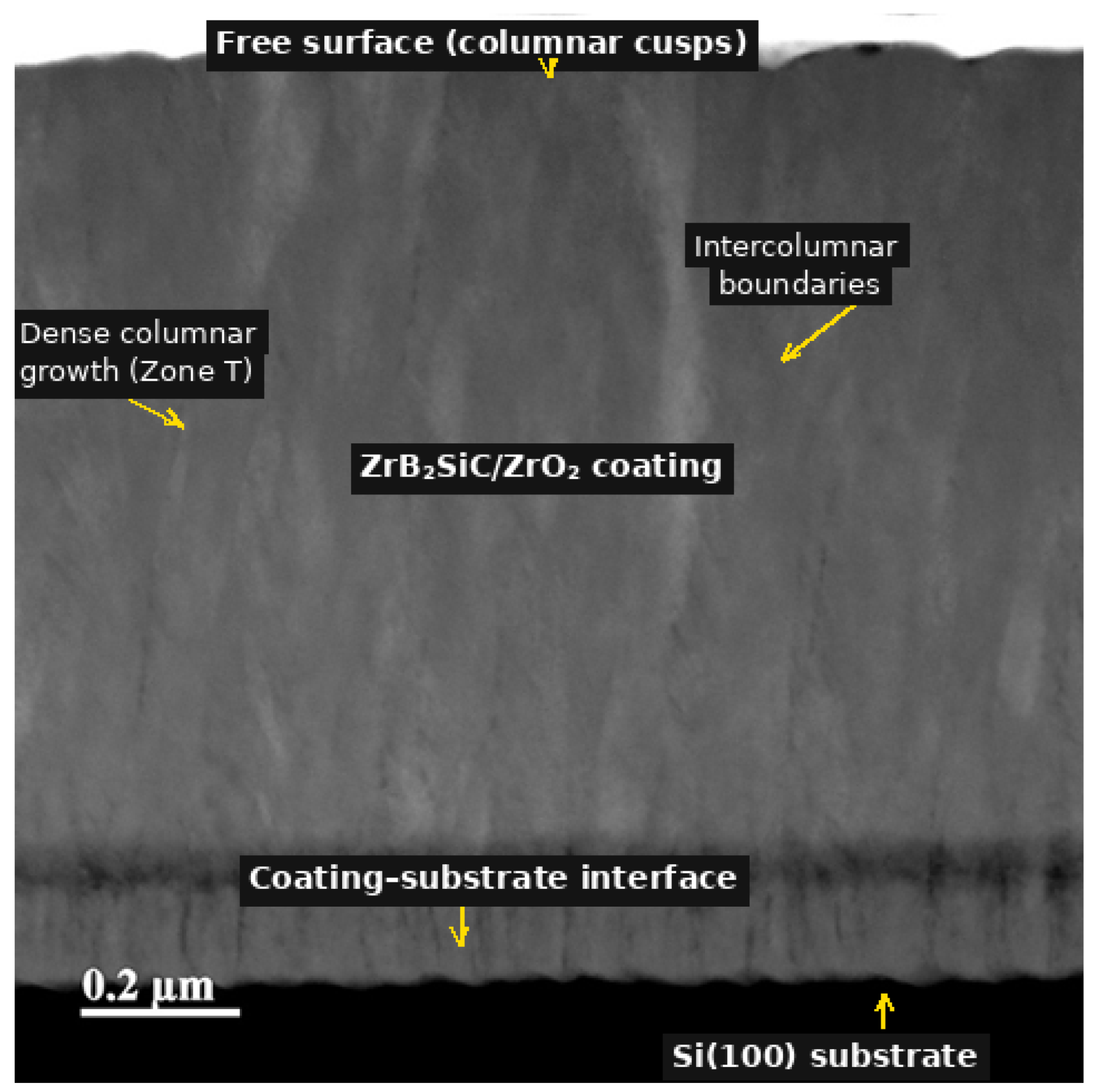
Figure 2 presents the SEM image of the cross-section of the ZrB2SiC/ZrO2 coating deposited on a Si(100) substrate, used as a model substrate for microstructural characterisation of the film. At the observation scale employed (scale bar: 0.2 μm), the coating microstructure exhibits dense, continuous columnar growth, with fine columns oriented perpendicular to the substrate surface and well-defined intercolumnar boundaries.
The density and regularity of the columns are consistent with the nanometric crystallite size of 24 ± 5 nm determined by XRD and correspond to Thornton’s Zone T growth model, characteristic of PVD films deposited under moderate working pressures and substrate temperatures [23]. In the present case, this morphology follows directly from the deposition window employed (Section 2.2): the substrate temperature of 300–400 °C corresponds to a homologous temperature regime in which adatom surface diffusion is sufficient to densify column boundaries but insufficient for bulk recrystallisation, while the applied bias of −50 to −100 V supplies the moderate ion bombardment that suppresses intercolumnar voids. The dense Zone T structure observed is therefore an expected and reproducible consequence of the selected deposition parameters rather than an incidental result, which is essential for the transferability of the coating process to industrial tool batches. The free surface of the coating displays a slightly undulating topography with regular columnar cusps, reflecting competitive growth between columns during deposition, in which favourable crystallographic orientations progressively predominate over unfavourable ones [24].
The absence of appreciable intercolumnar porosity indicates a high degree of film compaction, attributable to ion-assisted growth during PVD, which increases adatom surface mobility and suppresses void formation at intercolumnar boundaries [24]. This microstructural densification has direct implications for the coating’s mechanical properties, as residual porosity is a limiting factor for both hardness and crack propagation resistance under cyclic contact conditions.
The coating–substrate interface appears as a continuous, well-delineated dark line at the bottom of the image, with a narrow transition zone showing no evidence of extensive interfacial reactions or appreciable diffusion at the observation scale. The sharpness of this interface confirms the effectiveness of the ion activation process prior to deposition and the chemical compatibility between the coating and the model substrate employed [29].

3.2.2. Coating Coverage on the ASSAB-17 Tool Bit

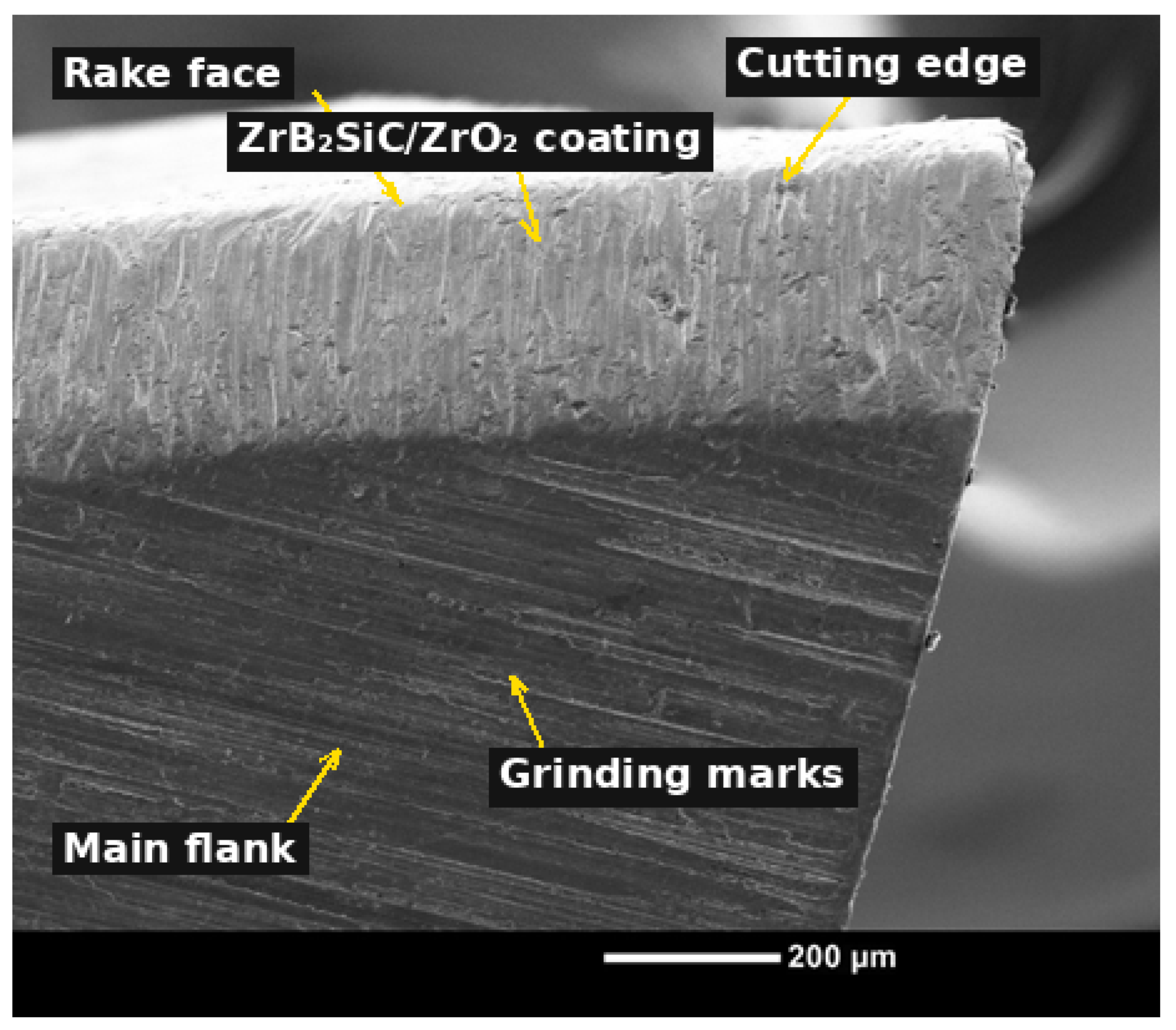
Figure 3 presents the SEM image of the cutting edge of the ASSAB-17 tool bit coated with ZrB2SiC/ZrO2, obtained at low magnification. The coating exhibits continuous, homogeneous coverage over all tool surfaces, including the rake face, the main flank and the cutting edge itself, with no macroscopic evidence of delamination, cracking or loss of adhesion in any of the observed regions.
On the rake face (upper region of the image), the coating displays a nodular-columnar surface morphology with a fine, rough texture, consistent with the columnar growth identified in the cross-section (Figure 2) and characteristic of UHTC coatings deposited by reactive magnetron sputtering [30]. On the main flank (lower region), grinding marks on the substrate, oriented parallel to the tool axis, remain visible beneath the coating, confirming the conformal nature of PVD growth, which faithfully replicates the pre-existing substrate topography [31]. This conformity over the complex edge geometry ensures uniform tribological protection of all active surfaces during turning.
The cutting edge shows a continuous, well-adhered coating with no localised stress concentration or chipping at the edge. Coating integrity in this region is particularly critical, as the cutting edge constitutes the region of greatest thermomechanical loading during dry turning of Ti-6Al-4V, where temperatures can exceed 800 °C and contact pressures reach 1–3 GPa [4].

3.3. Mechanical Properties of the Coating

3.3.1. Hardness and Reduced Elastic Modulus

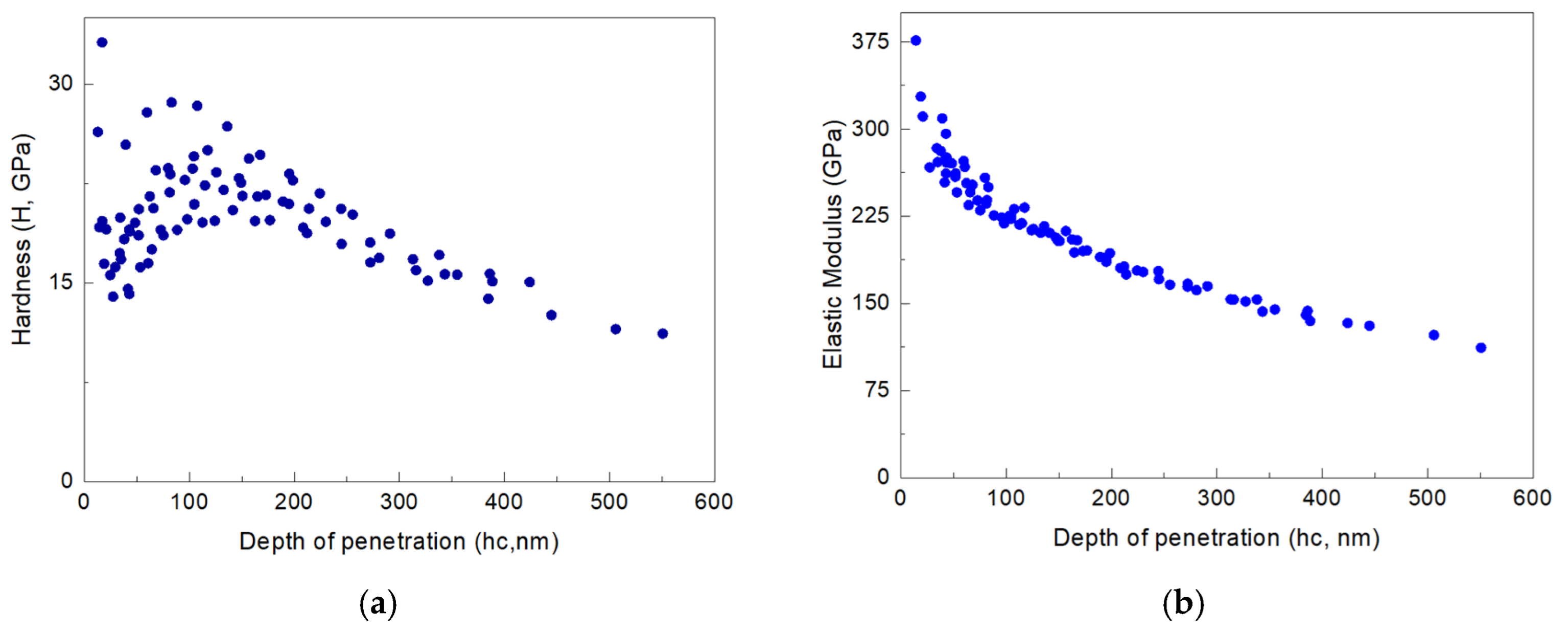
Figure 4a,b present the evolution of hardness (H) and reduced elastic modulus (Er) of the ZrB2SiC/ZrO2 coating as a function of contact penetration depth (hc), obtained by instrumented nanoindentation following the Oliver and Pharr method [32]. Plotting H and Er against hc allows identification of the mechanical response regimes associated with the coating, the interface, and the underlying substrate.
At low penetration depths (hc < 50 nm), both H and Er display considerable scatter, attributable to indentation size effects that distort the estimation of the projected contact area at low loads [33]. In the intermediate depth region (hc = 50–200 nm), corresponding to approximately 10% of the coating thickness, H and Er values show a more stable and consistent zone, representative of the film’s intrinsic properties. Within this range, coating hardness is estimated at H = 24 ± 3 GPa and the reduced elastic modulus at Er = 240 ± 20 GPa.
For depths above 200 nm, both quantities show a progressive, continuous decrease, consistent with the increasing influence of the ASSAB-17 high-speed steel substrate on the measured mechanical response, a phenomenon known as the substrate effect in nanoindentation of thin films [33]. At depths above 400 nm—representing more than 15% of the total coating thickness—H values converge towards ~13–15 GPa and Er towards ~100–130 GPa, consistent with the mechanical properties of uncoated ASSAB-17 high-speed steel [4].

3.3.2. Tribomechanical Resistance Parameters

From the H and Er values determined in the representative coating zone, the tribomechanical indices H/Er and H3/Er2 were calculated, widely used as indicators of wear resistance and elastic deformation capacity in hard coatings [26,34]. The obtained values are presented in Table 1.
The H/Er ratio of 0.100 exceeds the threshold of 0.08 typically associated with coatings exhibiting good resistance to elastic contact wear [26], indicating that the ZrB2SiC/ZrO2 coating possesses a high elastic deformation capacity that favours contact recovery without fracture under cyclic loading. The H3/Er2 index of 0.240 GPa, related to resistance against plastic deformation during contact, is comparable to values reported for high-performance hard ceramic coatings such as PVD-deposited TiAlN and CrAlN [34], suggesting favourable behaviour under the severe contact conditions characteristic of Ti-6Al-4V turning.
The measured hardness of 24 ± 3 GPa is consistent with values reported for nanostructured PVD-deposited ZrB2 systems, whose hardness typically lies in the 20–32 GPa range depending on composition, thickness and deposition conditions [9]. The incorporation of β-SiC and t-ZrO2 as secondary phases contributes to hardness retention through combined strengthening mechanisms of grain refinement, second-phase dispersion and phase transformation, respectively. Each of these contributions can be rationalised as follows. First, the 24 ± 5 nm crystallite size multiplies the density of grain boundaries that obstruct dislocation glide and shear band propagation, a Hall–Petch-type regime in which nanocrystalline ceramics retain high hardness [26,27]. Second, the dispersion of β-SiC introduces interphase boundaries with elastic modulus mismatch that deflect cracks and hinder the percolation of plastic deformation through the ZrB2 matrix [13,14]. Third, the metastable t-ZrO2 can transform martensitically to the monoclinic phase within the localised stress field of the indenter or the sliding contact; the associated volume expansion generates local compressive stresses that close incipient cracks and dissipate mechanical energy, contributing simultaneously to hardness retention and damage tolerance [15,16]. The combination of these mechanisms explains why the multiphase coating retains a hardness comparable to single-phase diboride films while providing additional toughening reserves that are directly relevant to the cyclic loading conditions of machining.

3.4. Frictional Behaviour and Transition Between Wear Regimes

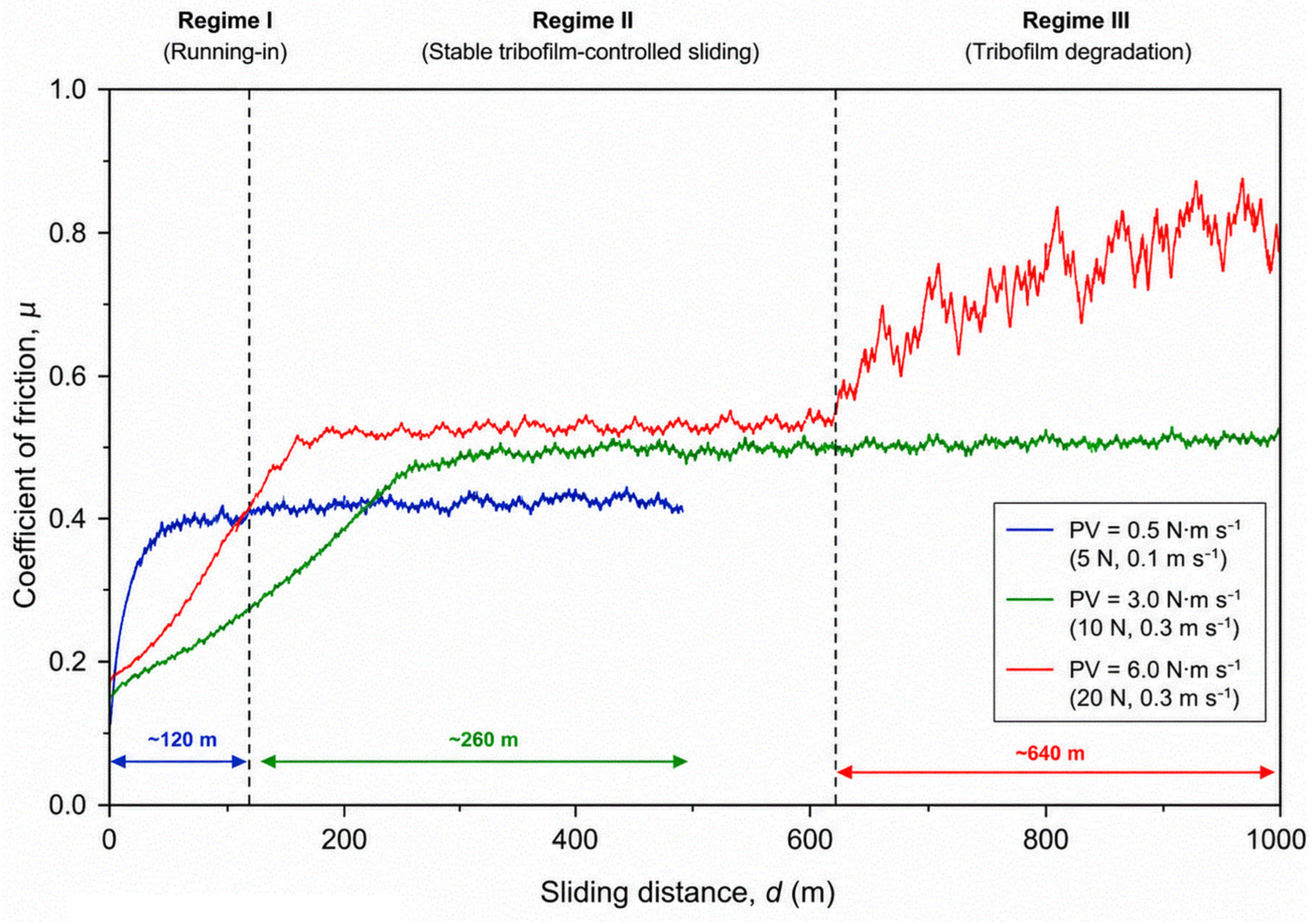
Figure 5 shows the evolution of the coefficient of friction (μ) as a function of sliding distance for the three severity conditions tested. In all cases, three characteristic stages are distinguished, whose duration and magnitude depend on the applied pressure–velocity (PV) product.
Under the lowest-severity condition (PV = 0.5 N·m/s), the coefficient of friction increases rapidly during a running-in period of approximately 120 m, reaching a stable value of around μ ~ 0.40–0.42 that remains without appreciable variation throughout the remainder of the evaluated distance (~490 m). This behaviour is consistent with the early formation of a continuous, mechanically stable tribofilm under low-contact pressure conditions, capable of sustaining a moderate, controlled friction regime (Regime II) with no evidence of degradation within the tested distance.
For the intermediate condition (PV = 3.0 N·m/s), the running-in period extends to approximately 260 m, with a more gradual increase in the coefficient of friction, stabilising at a value of μ ~ 0.50, higher than that observed under the lowest-severity condition. This more prolonged transition suggests that the formation of a continuous, protective tribofilm requires a greater running-in distance as the combination of load and velocity increases, although the system ultimately stabilises in a controlled sliding regime (Regime II), which persists without signs of degradation until the end of the evaluated distance.
Under the highest-severity condition (PV = 6.0 N·m/s), the coefficient of friction rises more rapidly in absolute terms, reaching values close to μ ~ 0.50–0.53 within the first ~150 m, in a manner initially similar to that observed under the intermediate condition. However, beyond approximately 620 m of sliding, the coefficient of friction begins to increase progressively and exhibits considerably greater scatter, reaching values of up to μ ~ 0.80–0.85 with marked fluctuations over the remaining ~380 m of the test, with no evidence of recovery towards a stable regime. This behaviour is characteristic of Regime III of progressive tribofilm degradation, in which the protective layer loses continuity under the more severe mechanical and thermal loading, intermittently exposing regions of lower tribological protection and favouring more aggressive wear mechanisms.
Taken together, the results in Figure 5 indicate that the PV product governs both the duration of the running-in period and the ability of the protective surface layer, inferred from the frictional response, to remain stable over time: at lower severity, the system rapidly reaches a low, stable friction regime; at intermediate severity, a longer running-in distance is required, but the stable regime is preserved, whereas at the highest severity evaluated, the tribofilm formed during Regime II fails to sustain itself indefinitely and ultimately degrades, giving rise to the transition to Regime III. This sequence is consistent with a mechanism whereby a tribofilm generated by tribochemical processes during contact regulates the frictional response of the system while it remains intact, with its progressive breakdown marking the transition to more severe wear states; the specific chemical composition of this tribofilm—potentially involving ZrO2, boron- and silica-based species, as reported for related UHTC systems in the literature—was not characterised directly in the present study and remains to be confirmed.

3.5. Specific Wear Rate and Comparison with Machining Tests

From the wear track geometry recorded by profilometry (Tesa Rugosurf 90G) at the conclusion of the pin-on-disc tests, the specific wear rate (k) was calculated for each severity condition using the Archard relation V = k · F · L, where V is the volume of material removed, F is the applied normal load, and L is the sliding distance. The obtained values are summarised in Table 2.
The specific wear rate (k) increased monotonically with contact severity, rising by more than one order of magnitude between the lowest-severity condition (PV = 0.5 N·m/s, k = 0.45 × 10⁻⁶ mm3/N·m) and the highest-severity condition (PV = 6.0 N·m/s, k = 4.80 × 10⁻⁶ mm3/N·m). This increase is consistent with the frictional transition described in Section 3.4: while the system remains in the stable sliding Regime II, the material removal rate stays comparatively low, consistent with the protective role attributed to the tribofilm; conversely, under the most severe condition, the loss of tribofilm continuity (Regime III) coincides with the most pronounced increase in k, suggesting that the frictional transition and the acceleration of volumetric wear are mechanically coupled.
The dry turning tests on Ti-6Al-4V yielded results consistent with the trend observed in the pin-on-disc tests. Maximum flank wear (VBmax), monitored in accordance with ISO 3685, evolved gradually during the running-in and stable moderate-wear stages, reaching values of 0.08–0.12 mm under low-severity conditions and 0.15–0.22 mm under intermediate severity, without reaching the tool life criterion (VBmax = 0.30 mm, ISO 3685) within the cutting conditions evaluated (Vc = 90 m·min−1, f = 0.10 mm·rev−1, ap = 0.70 mm). Under the high-severity condition, VBmax reached values of 0.32–0.48 mm, exceeding the standard end-of-life criterion and evidencing a marked acceleration of tool wear, consistent with the transition to Regime III identified in the tribological tests. This correspondence between laboratory frictional behaviour and tool wear under real machining conditions supports the practical relevance of the friction regimes identified in Section 3.4. It should nevertheless be noted that ball-on-disc sliding and turning differ substantially in contact geometry, temperature fields and the presence of chip formation and material transfer; the agreement observed here is therefore interpreted as consistency between the laboratory and machining responses—supporting the transferability of the PV-based severity concept—rather than as a strict validation of one test by the other.

4. Discussion

The results presented allow a coherent relationship to be established between the microstructure of the ZrB2SiC/ZrO2 coating, its mechanical properties, and its tribological response under progressively more severe contact conditions. The three-phase nanostructured architecture confirmed by XRD (ZrB2, β-SiC and t-ZrO2), together with the dense, columnar microstructure free of appreciable porosity observed by SEM, are consistent with the hardness values obtained (H = 24 ± 3 GPa) and with the tribomechanical indices H/Er = 0.100 and H3/Er2 = 0.240 GPa determined by nanoindentation, which place the coating within a favourable range of wear resistance and elastic deformation capacity, comparable to reference hard ceramic coatings such as TiAlN and CrAlN [26,34].
This microstructural foundation not only determines the coating’s initial mechanical strength but also directly conditions its subsequent capacity to generate and sustain a functional tribofilm. The homogeneous distribution of the ZrB2, β-SiC and t-ZrO2 phases within a dense columnar matrix would, in principle, favour a continuous supply of reactive species to the contact interface, constituting a plausible mechanistic starting point for the tribological behaviour observed [13,14]. In other words, the microstructure does not act as a passive background factor but as the enabling condition that may determine whether the layer formed during sliding is continuous and protective or discontinuous and prone to premature breakdown.
This combination of high hardness and elastic accommodation capacity explains, at least in part, the coating’s ability to sustain a stable sliding regime (Regime II) throughout a significant fraction of the tribological life under the low- and medium-severity conditions evaluated. Although the composition and crystalline structure of this layer were not directly characterised in the present study, the sustained reduction in the coefficient of friction during this regime is consistent with the formation of a low-shear strength surface layer, whose presence would protect the underlying ceramic matrix from direct contact with the counterbody. This behaviour is compatible with the role attributed in the literature to silica-based phases and boron-rich oxides as tribochemically active species in ZrB2-SiC systems [13,18,19], although their actual formation under the specific conditions of this work could not be confirmed compositionally and should be regarded as a reasonable mechanistic hypothesis rather than a direct experimental finding.
The transition towards Regime III, observed only under the highest-severity condition (PV = 6.0 N·m/s), suggests the existence of a mechanical and thermal loading threshold above which the degradation rate of the protective layer would exceed its regeneration rate [18,21], compromising its continuity and progressively exposing the ceramic matrix to direct contact with the counterbody. This interpretation is consistent with the unstable frictional behaviour observed under this condition, although direct characterisation of the microstructural or compositional evolution of the contact surface remains a line of future work that would allow the proposed mechanism to be confirmed.
The specific wear rate (k) and the maximum flank wear (VBmax) reinforce the proposed mechanistic interpretation. The more than one order of magnitude increase in k between the lowest- and highest-severity conditions (0.45 × 10⁻⁶ to 4.80 × 10⁻⁶ mm3/N·m) is not gradual but is concentrated principally at the transition to Regime III observed under PV = 6.0 N·m/s, suggesting that the loss of frictional stability under this condition coincides with and likely enables substantially more aggressive material removal. Similarly, exceedance of the tool life criterion (VBmax = 0.30 mm, ISO 3685) occurred exclusively under the highest-severity condition, in direct correspondence with the loss of frictional stability identified in the pin-on-disc tests. This coincidence between laboratory tribological behaviour and tool performance under real machining conditions supports the existence of a mechanical and thermal loading threshold associated with the PV product above which the system ceases to sustain a controlled wear regime.
Taken together, these results allow an integrated mechanistic chain to be proposed: the three-phase nanostructured microstructure determines the coating’s mechanical properties and, presumably, its capacity to sustain a protective layer at the contact interface; this layer appears to control the frictional behaviour of the system while it remains stable; the loss of this stability, favoured by an increasing PV product, coincides with the transition to an unstable friction regime, a discrete jump in the specific wear rate, and an abrupt acceleration of flank wear under real machining conditions, in line with the load- and severity-driven transitions reported for related coated systems [8,21,34]. This correspondence supports the existence of a mechanical and thermal loading threshold that is useful as a design criterion, although direct compositional confirmation of the proposed tribochemical mechanisms requires complementary studies (for example, EDS or GIXRD analysis of worn surfaces).
Finally, the scope of the mechanistic interpretation proposed above must be explicitly delimited. The experimental programme did not include surface-sensitive chemical analyses of the wear tracks (e.g., XPS, Raman spectroscopy, TEM, ToF-SIMS or EDS elemental mapping), nor cross-sectional examination of the tribological layer; consequently, its chemical composition, thickness, continuity and internal structure could not be determined, and it cannot be established whether the layer formed during sliding is continuous or how it evolves with increasing load. Likewise, XRD analyses were performed only prior to tribological testing, so the possible formation of new crystalline phases during sliding could not be verified. The tribofilm formation–stabilisation–degradation sequence discussed in this work should therefore be regarded as a phenomenological model, supported by the frictional response, the evolution of the specific wear rate and the SEM morphology of the worn surfaces, and consistent with tribochemical processes reported for related ZrB2–SiC systems, rather than as a conclusively demonstrated mechanism. Post-test compositional and cross-sectional characterisation of the worn surfaces therefore constitutes the necessary continuation of this work.

5. Conclusions

The tribological behaviour of ZrB2SiC/ZrO2 coatings deposited by PVD onto ASSAB-17 high-speed steel tool bits was evaluated under three severity levels defined by the pressure–velocity (PV) product and compared with the results of dry turning tests on Ti-6Al-4V alloy. The following conclusions can be drawn:
  • The coating developed a three-phase nanostructured architecture comprising ZrB2, β-SiC and t-ZrO2, with a crystallite size of 24 ± 5 nm and a dense, columnar, essentially pore-free microstructure, confirming that the deposition parameters employed were suitable to achieve the intended phase composition and structural integrity.
  • This microstructure underpinned favourable mechanical properties (H = 24 ± 3 GPa, Er = 240 ± 20 GPa, H/Er = 0.100, H3/Er2 = 0.240 GPa), comparable to reference hard ceramic coatings such as TiAlN and CrAlN and consistent with good resistance to elastic contact wear and plastic deformation.
  • Three distinct frictional regimes were identified across all severity conditions: an initial running-in stage, a stable sliding regime, and, under the highest-severity condition only, a progressive degradation regime. Increasing PV delayed the running-in period (from ~120 m to ~260 m) and, at PV = 6.0 N·m/s, triggered a transition to unstable, high-friction behaviour beyond ~620 m.
  • This frictional transition coincided with a more than one order of magnitude increase in specific wear rate (from 0.45 × 10⁻⁶ to 4.80 × 10⁻⁶ mm3/N·m), concentrated principally at the highest-severity condition, indicating that the loss of frictional stability and the acceleration of material removal are closely coupled.
  • Dry turning tests were consistent with this trend: maximum flank wear (VBmax) remained below the ISO 3685 tool life criterion (0.30 mm) under low- and medium-severity conditions but exceeded it exclusively under the highest-severity condition, in direct correspondence with the loss of stability observed in the pin-on-disc tests.
  • Taken together, these findings support the existence of a mechanical and thermal severity threshold, associated with the PV product, above which the protective surface layer formed during sliding can no longer be sustained, leading to a coupled transition in friction, wear rate and tool life. While the compositional and structural evolution of this layer was not directly characterised in the present work, the proposed mechanism—presented as a working hypothesis linking coating microstructure, frictional stability and wear transition—provides a practical criterion for the design and selection of UHTC coatings for the machining of titanium alloys under demanding operating conditions. Direct compositional characterisation of the worn surfaces (e.g., by EDS or GIXRD) is recommended as a priority for future work to confirm the tribochemical mechanisms proposed.

Author Contributions

Conceptualization, W.A. and J.C.C.; methodology, W.A. and J.C.C.; software, W.A.; validation, W.A., G.O.-H. and J.C.C.; formal analysis, W.A. and J.C.C.; investigation, W.A., G.O.-H. and J.C.C.; resources, W.A. and J.C.C.; data curation, W.A.; writing—original draft preparation, W.A.; writing—review and editing, W.A., G.O.-H. and J.C.C.; visualisation, W.A.; supervision, W.A. and J.C.C.; project administration, W.A. All authors have read and agreed to the published version of the manuscript.

Funding

This research received no external funding.

Data Availability Statement

The data presented in this study are available on request from the corresponding author.

Acknowledgments

The authors would like to thank Universidad Militar Nueva Granada, Universidad ECCI, and Universidad del Valle for providing the institutional and technical support necessary to carry out this work.

Conflicts of Interest

The authors declare no conflicts of interest.

References

  1. Rech, J.; Arrazola, P.J.; Claudin, C.; Courbon, C.; Pusavec, F.; Kopac, J. Characterisation of friction and heat partition coefficients at the tool-work material interface in cutting. CIRP Ann. 2013, 62, 79–82. [Google Scholar] [CrossRef] [Scilit]
  2. Gekonde, H.O.; Subramanian, S.V. Tribology of tool–chip interface and tool wear mechanisms. Surf. Coat. Technol. 2002, 149, 151–160. [Google Scholar] [CrossRef] [Scilit]
  3. Ezugwu, E.O.; Wang, Z.M. Titanium alloys and their machinability—A review. J. Mater. Process. Technol. 1997, 68, 262–274. [Google Scholar] [CrossRef] [Scilit]
  4. Atlati, S.; Moufki, A.; Nouari, M.; Haddag, B. Interaction between the local tribological conditions at the tool–chip interface and the thermomechanical process in the primary shear zone when dry machining the aluminum alloy AA2024–T351. Tribol. Int. 2017, 105, 326–333. [Google Scholar] [CrossRef] [Scilit]
  5. Carrion, P.E.; Shamsaei, N.; Daniewicz, S.R.; Moser, R.D. Fatigue behavior of Ti-6Al-4V ELI including mean stress effects. Int. J. Fatigue 2017, 99, 87–100. [Google Scholar] [CrossRef] [Scilit]
  6. Sharma, P.; Mishra, S.K.; Ramkumar, J. Characterization and wear performance of advanced AlTiSiN-based coated cutting tools in dry machining of Ti-6Al-4V alloy. J. Manuf. Process. 2025, 150, 485–500. [Google Scholar] [CrossRef] [Scilit]
  7. Ezugwu, E.O. Key improvements in the machining of difficult-to-cut aerospace superalloys. Int. J. Mach. Tools Manuf. 2005, 45, 1353–1367. [Google Scholar] [CrossRef] [Scilit]
  8. Chowdhury, M.S.I.; Chowdhury, S.; Yamamoto, K.; Beake, B.D.; Bose, B.; Elfizy, A.; Covelli, D.; Dosbaeva, G.; Aramesh, M.; Fox-Rabinovich, G.S.; et al. Wear behaviour of coated carbide tools during machining of Ti6Al4V aerospace alloy associated with strong built up edge formation. Surf. Coat. Technol. 2017, 313, 319–327. [Google Scholar] [CrossRef] [Scilit]
  9. Sim, G.-D.; Choi, Y.S.; Lee, D.; Oh, K.H.; Vlassak, J.J. High tensile strength of sputter-deposited ZrB2 ceramic thin films measured up to 1016 K. Acta Mater. 2016, 113, 32–40. [Google Scholar] [CrossRef] [Scilit]
  10. Fahrenholtz, W.G.; Hilmas, G.E. Ultra-high temperature ceramics: Materials for extreme environments. Scr. Mater. 2017, 129, 94–99. [Google Scholar] [CrossRef] [Scilit]
  11. Li, J.; Chen, Y.; Zhao, L.; Li, Z. Research development of ultra-high temperature ceramics. AIP Adv. 2025, 15, 090701. [Google Scholar] [CrossRef] [Scilit]
  12. Zhang, S.C.; Hilmas, G.E.; Fahrenholtz, W.G. Pressureless sintering of ZrB2–SiC ceramics. J. Am. Ceram. Soc. 2008, 91, 26–32. [Google Scholar] [CrossRef] [Scilit]
  13. Silvestroni, L.; Sciti, D.; Melandri, C.; Guicciardi, S. Toughened ZrB2-based ceramics through SiC whisker or SiC chopped fiber additions. J. Eur. Ceram. Soc. 2010, 30, 2155–2164. [Google Scholar] [CrossRef] [Scilit]
  14. Guo, S.Q. Densification of ZrB2-based composites and their mechanical and physical properties: A review. J. Eur. Ceram. Soc. 2009, 29, 995–1011. [Google Scholar] [CrossRef] [Scilit]
  15. Kelly, P.M.; Rose, L.R.F. The martensitic transformation in ceramics—Its role in transformation toughening. Prog. Mater. Sci. 2002, 47, 463–557. [Google Scholar] [CrossRef] [Scilit]
  16. Hannink, R.H.J.; Kelly, P.M.; Muddle, B.C. Transformation toughening in zirconia-containing ceramics. J. Am. Ceram. Soc. 2000, 83, 461–487. [Google Scholar] [CrossRef] [Scilit]
  17. Xu, Y.; Yu, W.; Liao, X.; Zhu, Y.; Su, B. Effect of gradient layer induced by laser shock peening on adhesion and wear resistance of AlCrN coatings on TC4 titanium alloy. Materials 2026, 19, 608. [Google Scholar] [CrossRef] [Scilit] [PubMed]
  18. Yang, Q.; Senda, T.; Kotani, N.; Hirose, A. Sliding wear behavior and tribofilm formation of ceramics at high temperatures. Surf. Coat. Technol. 2004, 184, 270–277. [Google Scholar] [CrossRef] [Scilit]
  19. Gupta, Y.; Kumar, B.V.M. ZrB2–SiC composites for sliding wear contacts: Influence of SiC content and counterbody. Ceram. Int. 2022, 48, 14560–14567. [Google Scholar] [CrossRef] [Scilit]
  20. Prakasarao, C.S.; Nadeem, I.; Kalin, M.; Kumar, B.V.M. Development of electrical discharge machinable SiC-ZrN composites: Unveiling high temperature sliding wear resistance. J. Eur. Ceram. Soc. 2025, 45, 117040. [Google Scholar] [CrossRef] [Scilit]
  21. Munir, S.; Zambrano, D.; Moncada, D.; Soler, M.; Rosenkranz, A. Load-driven tribofilm formation: Friction-wear trade-off in Ti2AlN and Ti2NTx multilayered nanosheet coatings. ACS Appl. Nano Mater. 2026, 9, 9138–9151. [Google Scholar] [CrossRef] [Scilit]
  22. ISO 3685; Tool Life Testing with Single-Point Turning Tools. International Organization for Standardization: Geneva, Switzerland, 1993.
  23. Thornton, J.A. Influence of apparatus geometry and deposition conditions on the structure and topography of thick sputtered coatings. J. Vac. Sci. Technol. 1974, 11, 666–670. [Google Scholar] [CrossRef] [Scilit]
  24. Petrov, I.; Barna, P.B.; Hultman, L.; Greene, J.E. Microstructural evolution during film growth. J. Vac. Sci. Technol. A 2003, 21, S117–S128. [Google Scholar] [CrossRef] [Scilit]
  25. Magnuson, M.; Hultman, L.; Högberg, H. Review of transition-metal diboride thin films. Vacuum 2022, 196, 110567. [Google Scholar] [CrossRef] [Scilit]
  26. Leyland, A.; Matthews, A. On the significance of the H/E ratio in wear control: A nanocomposite coating approach to optimised tribological behaviour. Wear 2000, 246, 1–11. [Google Scholar] [CrossRef] [Scilit]
  27. Ryou, H.; Drazin, J.W.; Wahl, K.J.; Qadri, S.B.; Gorzkowski, E.P.; Feigelson, B.N.; Wollmershauser, J.A. Below the Hall–Petch limit in nanocrystalline ceramics. ACS Nano 2018, 12, 3083–3094. [Google Scholar] [CrossRef] [Scilit] [PubMed]
  28. Ji, Z.; Haynes, J.; Ferber, M.; Rigsbee, J. Metastable tetragonal zirconia formation and transformation in reactively sputter deposited zirconia coatings. Surf. Coat. Technol. 2001, 135, 109–117. [Google Scholar] [CrossRef] [Scilit]
  29. Panjan, P.; Drnovšek, A.; Čekada, M.; Panjan, M. Contamination of substrate-coating interface caused by ion etching. Coatings 2022, 12, 846. [Google Scholar] [CrossRef] [Scilit]
  30. de Monteynard, A.; Luo, H.; Chehimi, M.; Ghanbaja, J.; Achache, S.; François, M.; Billard, A.; Sanchette, F. The structure, morphology, and mechanical properties of Ta-Hf-C coatings deposited by pulsed direct current reactive magnetron sputtering. Coatings 2020, 10, 212. [Google Scholar] [CrossRef] [Scilit]
  31. Panjan, P.; Drnovšek, A.; Mahne, N.; Čekada, M.; Panjan, M. Surface topography of PVD hard coatings. Coatings 2021, 11, 1387. [Google Scholar] [CrossRef] [Scilit]
  32. Oliver, W.C.; Pharr, G.M. An improved technique for determining hardness and elastic modulus using load and displacement sensing indentation experiments. J. Mater. Res. 1992, 7, 1564–1583. [Google Scholar] [CrossRef] [Scilit]
  33. Zak, S.; Trost, C.O.W.; Kreiml, P.; Cordill, M.J. Accurate measurement of thin film mechanical properties using nanoindentation. J. Mater. Res. 2022, 37, 1373–1389. [Google Scholar] [CrossRef] [Scilit]
  34. Deng, J.; Wu, F.; Lian, Y.; Xing, Y.; Li, S. Erosion wear of CrN, TiN, CrAlN, and TiAlN PVD nitride coatings. Int. J. Refract. Met. Hard Mater. 2012, 35, 10–16. [Google Scholar] [CrossRef] [Scilit]
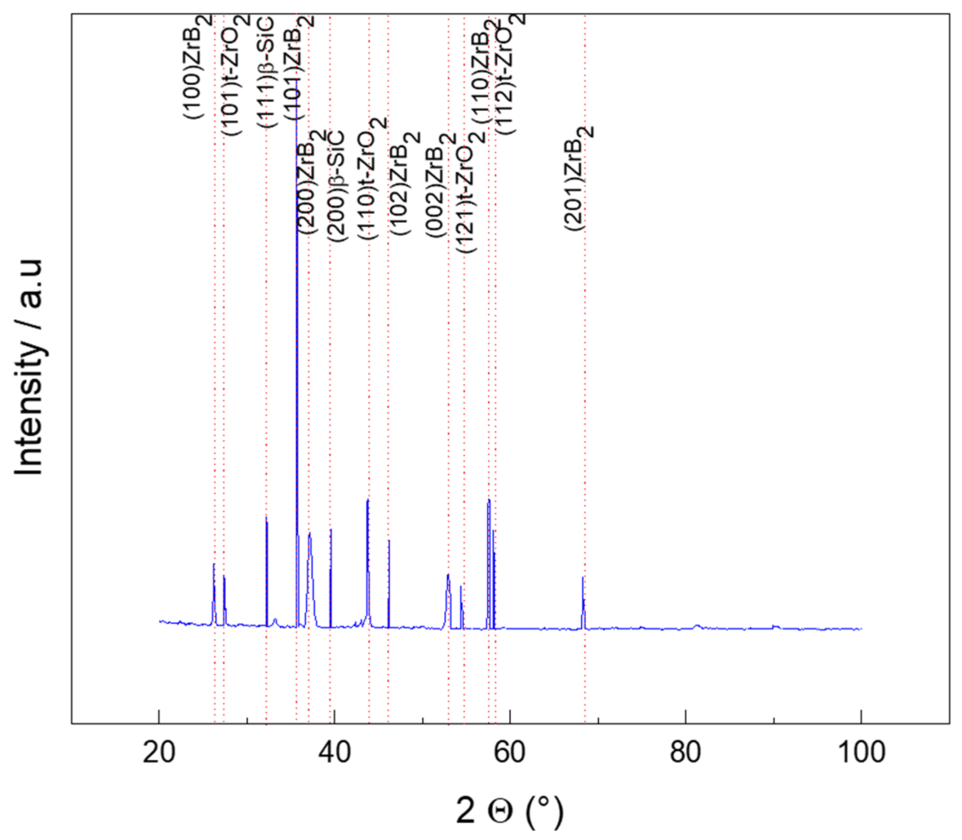
Figure 1. X-ray diffractogram of the ZrB2SiC/ZrO2 coating deposited by PVD onto an ASSAB-17 tool bit. The ZrB2 (JCPDS 34-0423), β-SiC (JCPDS 29-1129) and t-ZrO2 (JCPDS 42-1164) crystalline phases are identified. Cu Kα radiation (λ = 0.15406 nm), range 20–100° (2θ), angular step 0.02°, scan rate 2° min−1.
Solids 07 00039 g001
Figure 2. SEM image of the cross-section of the ZrB2SiC/ZrO2 coating deposited by PVD on a Si(100) substrate. The dense columnar morphology, undulating free surface topography, and well-defined coating–substrate interface are visible. Scale bar: 0.2 μm. The total film thickness is ≈3 μm (Section 2.2).
Solids 07 00039 g002
Figure 3. SEM image of the cutting edge of the ASSAB-17 tool bit coated with ZrB2–SiC/ZrO2 by PVD. Continuous, homogeneous coating coverage is observed on the rake face, main flank and cutting edge. Scale bar: 200 μm. The nominal coating thickness on the tool is ≈3 μm (Section 2.2); at this magnification the film thickness is not resolvable, and the cross-sectional structure is documented in Figure 2.
Solids 07 00039 g003
Figure 4. (a) Hardness (H) as a function of contact penetration depth (hc) for the ZrB2SiC/ZrO2 coating deposited on the ASSAB-17 tool bit, obtained by instrumented nanoindentation. (b) Reduced elastic modulus (Er) as a function of contact penetration depth (hc) for the ZrB2SiC/ZrO2 coating, obtained by instrumented nanoindentation.
Solids 07 00039 g004
Figure 5. Evolution of the coefficient of friction (μ) as a function of sliding distance (d) for the ZrB2-SiC/ZrO2 coating on an ASSAB-17 tool bit, obtained by pin-on-disc tests under three severity conditions defined by the pressure–velocity product: PV = 0.5 N·m/s (5 N, 0.1 m/s), PV = 3.0 N·m/s (10 N, 0.3 m/s) and PV = 6.0 N·m/s (20 N, 0.3 m/s). Three friction regimes are identified: Regime I (running-in), Regime II (steady-state sliding, attributed to tribofilm control) and Regime III (progressive degradation of the protective layer).
Solids 07 00039 g005
Table 1. Mechanical properties and tribomechanical indices of the ZrB2–SiC/ZrO2 coating.
ParameterValue
Hardness, H (GPa)24 ± 3
Reduced elastic modulus, Er (GPa)240 ± 20
H/Er ratio0.100 ± 0.008
H3/Er2 index (GPa)0.240 ± 0.06
Table 2. Coefficient of friction, specific wear rate (k) and volume of material removed for each tribological severity condition tested.
ConditionLoad (N)Distance (m)Average μk (mm3/N·m)
PV = 0.5 N·m·s−15500≈0.410.45 × 10−6
PV = 3.0 N·m·s−1101000≈0.501.10 × 10−6
PV = 6.0 N·m·s−1201000≈0.76–0.854.80 × 10−6
Disclaimer/Publisher’s Note: The statements, opinions and data contained in all publications are solely those of the individual author(s) and contributor(s) and not of MDPI and/or the editor(s). MDPI and/or the editor(s) disclaim responsibility for any injury to people or property resulting from any ideas, methods, instructions or products referred to in the content.