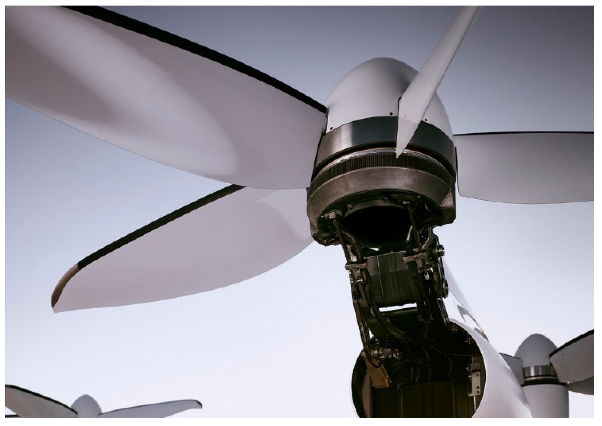
Proceeding Paper

Overview of Electric Propulsion Motor Research for EVTOL †

AVIC Xi’an Flight Automatic Control Research Institute, Xi’an 710076, China
*
Author to whom correspondence should be addressed.
Presented at the 2nd International Conference on Green Aviation (ICGA 2024), Chengdu, China, 6–8 November 2024.
Eng. Proc. 2024, 80(1), 46; https://doi.org/10.3390/engproc2024080046
Published: 7 May 2025
(This article belongs to the Proceedings of 2nd International Conference on Green Aviation (ICGA 2024))

Abstract

Electric aviation is the future development direction of aviation industry technology. Electric vertical take-off and landing aircraft(eVTOL) is an important carrier of electric aviation, whose technology research and development, processing and manufacturing, airworthiness certification and industrialization boom have been set off around the world. The electric propulsion technology has achieved rapid development as the key technology of eVTOL. Aiming at the demand for high torque density and high reliability of electric propulsion system, the paper analyzed the technical indexes of electric motor products of domestic and foreign benchmark enterprises. The key technologies such as motor integration, new electromagnetic topology, lightweight structure design, and high efficiency cooling is studied. It is pointed out that in order to pursue the high torque density and fault-tolerance performance, the integrated precise modeling of motor and controller, advanced materials and manufacturing technology are the development trend of the electric propulsion technology. The breakthrough of eVTOL electric propulsion technology can accelerate the commercial operation of civil eVTOL and promote the development of new quality productive forces.

1. Introduction

Electric aviation technology is known as a typical symbol of the cross-generation development of the aviation industry, which has technical advantages such as high efficiency, low noise and zero emission, and has become a basic and strategic technology that all countries are competing to develop. As the carrier of electric aviation technology, electric vertical take-off and landing aircraft promote the rapid development of new quality productivity represented by low-altitude intelligent transportation, which is an important part of the high-tech industry of national economy.
The core technology of eVTOL mainly includes aerodynamic overall, flight control system, avionics system, propulsion system, in which the propulsion system, as the power source of eVTOL, directly determines the function, performance and safety of eVTOL. With the emergence of new eVTOL configurations such as tilt-rotor, the coupling between electric propulsion system and aerodynamic overall, flight control system is closer to that of traditional fixed-wing and helicopter. With the emergence of new eVTOL configurations such as tilt rotor, the coupling between electric propulsion system, aerodynamic system and flight control system is closer than that of traditional fixed-wing and helicopter, and it is developing in the direction of high efficiency and high reliability.

2. The Status Quo at Home and Abroad

Electric propulsion technology belongs to the cutting-edge technology, which improves the dynamic characteristics, reliability and handling quality of eVTOL, and foreign countries have continuously invested in it, and have already formed rich theoretical accumulation and engineering experience.Joby, Magnix, etc. have carried out the research on electric propulsion technology, and realized the test flights of the installed aircraft. Among them, Joby’s electric propulsion motor adopts direct-drive double-winding structure, with peak power of 236 kW and rated torque density as high as 49 Nm/kg, as shown in Table 1. Under the support of USAF’s “Agile Above All” program, Joby has already completed the verification of this type of electric propulsion motor in the tilting hexacopter, as shown in Figure 1, and has also delivered the first eVTOL to the USAF [1].
Magnix is a star startup company of all-electric propulsion system, which has developed modularized motors and electronic control, which reduces the cost and improves the maintainability and expandability, and its main products include two types of motors magni250 and magni500 and one type of controller magniDrive100, in which magni250 motor is used in combination with two sets of magniDrive100 controllers to form a motor drive system, as shown in Figure 2, magni500 motor is used in combination with four sets of magniDrive100 controllers, and its rated power is 560 kW. The main products include two types of motors magni250, magni500 and one type of controller magniDrive100, of which magni250 motors are combined with two sets of magniDrive100 controllers to form a motor drive system, as shown in Figure 2. magni500 motors are combined with four sets of magniDrive100 controllers, with a rated power of 560 kW [2], and the main performance parameters are listed in Table 2.
Aviation benchmark enterprise Safran Group developed ENGINeUSTM series electric propulsion motors, as illustrated in Figure 3, the power level covers 50–1 MW, voltage up to 850 V, typical speed range of 1500–4500 rpm, the use of motors, controllers, integrated integrated design scheme, including power conversion, protection, thermal management and other functions, the peak power density of 5 kW/kg, and is applying for airworthiness certification [3].
Siemens developed the SP260D direct-drive electric propulsion motor with a rated power of 260 kW, rated speed of 2500 rpm, rated torque of 1000 Nm, weight of 50 kg, and torque density of 20 Nm/kg, as illustrated in Figure 4 [4].
Electropropulsion newcomer H3X has received investment from Lockheed Martin and is actively developing a highly integrated modular aero-motor system, which is designed with a hexagonal scheme for the motor system enclosure, which dramatically reduces the weight and cost of connectors and cables by integrating all the components such as the inverter of the electro-propulsion into a single enclosure, as shown in Figure 5, in which the HPDM-250 contains both the direct-drive and the with reducer scheme two types of products, the motor system power density of 13 kW/kg [5], as shown in Table 3.
Emrax has developed a spectrum of products such as 208, 228, 268, and 348 by using the scheme of dual-rotor, single-stator axial flux motors as shown in Figure 6, with a rated power range of 15–200 kW and a peak power coverage of 60–400 kW, among which the EMRAX348 motor has a rated torque density of 12.5 Nm/kg and a rated power density of 5 kW/kg, and the main parameters are shown in Table 4 [6].
Evolito has developed the D1500 axial flux motor for electric airplanes, as shown in Figure 7.The motor adopts a dual three-phase topology, which effectively improves the reliability, and has a rated torque density of 35 Nm/kg [7]. Its main parameters are shown in Table 5.
Domestically, Tianjin SANTROLL Intelligent Equipment Co., Ltd. is committed to the research of various electric drive system technologies, and its main products are flat-wire motors and controller core components, with mature automated flat-wire motor production lines, and has successively developed flat-wire motors with stator sizes ranging from 180–445 mm and power ranging from 30–400 kW, as shown in Figure 8, which are widely used in electric load-carrying unmanned aerial vehicles and other fields [8].
Shandong Jingchuang Magnetron Industrial Technology Research Institute Co., Ltd. owns the core technology of ‘’new high-efficiency and lightweight motor’’ and focuses on the R&D and innovation of electric aviation motors and system application solutions, including the customized development of aviation motor controller matching, aircraft propeller, thermal management system, and aviation connectors and wiring harnesses, and has formed a spectrum of motor products with rated power of 10–90 kW. Rated power 10–90 kW spectrum of motor products, the main performance parameters are shown in Table 6, the motor and controller photos are shown in Figure 9 [9].
Driven by the development of low-altitude economy, domestic and foreign enterprises have carried out extensive research on eVTOL technology, and layout configurations such as multi-rotor, composite wing, tilt-rotor, and tilt-culvert have appeared, and traction electric propulsion motors have developed towards high-voltage, high-power, and high-efficiency. Foreign electric propulsion motor research covers ten kW level to MW level, 500 kW level has formed products, in the installed test flight, airworthiness certification and other aspects of the forefront, and torque density, power density, efficiency and other technical indicators advanced, the gap between the domestic and foreign compared to a large gap, so there is an urgent need to analyze the core technology of electric propulsion motor, support the development of eVTOL civil aircraft.

3. Research on Key Technologies for Electric Propulsion Motors

Low-altitude intelligent transportation pursues safety, convenience, comfort, and economy, which requires eVTOL to have high cruising speed, range, and payload, and the electric propulsion system powers it toward high reliability, high efficiency, and lightweight, especially when flying over the city, it puts forward more demanding requirements on noise, and the slurry tip speed is an important indicator to reflect the aerodynamic noise:
v = P T R
where, v is the tip speed, P is the propeller power, T is the torque, R is the rotation radius.
The aerodynamic noise can be effectively reduced by reducing the pulp tip speed, while the propeller power and rotation radius is determined by the eVTOL size, configuration, and pulp disk load, so the torque of the electric propulsion system should be improved, and the torque density of the motor must be improved under the requirement of lightweighting.
The torque density, efficiency, power-to-weight ratio, and fault-tolerant performance of the motor system can be effectively improved by adopting the integrated and integrated design of motor and controller, new electromagnetic topology, and high-efficiency heat dissipation technology.

3.1. Integrated Design Technology

Joby adopts an integrated motor and controller design scheme, as shown in Figure 10, where the integrated motor drive system is mounted between the propeller and the nacelle [10]. When the tilting mechanism is located at the rear end of the nacelle, the electric propulsion system and the nacelle are tilted as a whole during the modal switching of takeoff, cruise, hovering, and landing, as shown in Figure 10, whereas the tilting mechanism is located at the front end of the nacelle, the position of the eVTOL remains unchanged when the eVTOL is in flight. When mode switching, only the propulsion system is tilted, and the position of the nacelle is fixed, as illustrated in Figure 10.
The integrated motor drive system integrates air cooling and liquid cooling system inside, including radiator, fan, pump, accumulator, control system, and motor, as shown in Figure 11, the control system mainly includes three major components, namely, control board, power board 1, and power board 2, where the control board contains functions such as propulsion motor control, pitch control, tilt control, and pump control, etc., and the control board is located between the Power Board 1, and the Power Board 2, which shortens the alignment between the Control Board. The Control Board is located between the Power Board 1 and Power Board 2, which shortens the alignment between the Control Board and each Power Board and realizes a compact structural layout. The coolant starts from the radiator, first flows through the stator winding of the motor, then enters the inside of the control system, passes through the cavity between the control board and the power board 2, and then flows through the heat dissipation cavity at the bottom of the motor inverter, then flows through the pump, and finally returns to the radiator to realize the circulation, and the accumulator can realize the replenishment of the coolant pressure. The fan can strengthen the air-cooling heat dissipation effect of the motor inverter or even the whole control system, and induce the heat from the inside of the radiator to be transferred to the outside of the radiator, and the rotation of the propeller further accelerates the heat exchange between the radiator and the air, ensuring the thermal safety of the system. The compact structure of the whole motor drive system shortens the power alignment, which reduces the electromagnetic interference from the internal power part of the motor drive system to the control part, and at the same time, the whole system is surrounded by a metal cover, which reduces the external electromagnetic radiation.
Aviation benchmark enterprise Honeywell for electric/hybrid vehicles, the thermal management system, motor, electronic control integrated in the electric propulsion system, as shown in Figure 12, the motor and controller share the same housing, the housing is equipped with air intake and exhaust ports, the use of air-cooling to achieve the cooling of the motor and the controller, the thermal management system mainly consists of: high-speed airflow brought about by the rotation of the propeller, a manifold-based micro-channel radiator, pseudo-side-wound stator winding, and high-temperature resistant enameled wire [11], in which the manifold-based micro-channel radiator is integrated into the housing, which effectively reduces the air intake resistance and enhances the air-cooling effect of the stator part of the system, especially the motor windings and controller power tubes, and at the same time, the insulation between the windings and the bottom of the slots is connected through a thermally conductive pad, which reduces the contact thermal resistance between the windings and the stator core, and moreover, the rotor of the motor adopts a hollow structure, which introduces high-speed airflow into the rotor to realize the cooling of the magnet and controller, and the air flow is introduced to the rotor. In addition, the rotor of the motor adopts hollow structure, which introduces high-speed airflow into the rotor and realizes air-cooling of the magnets. The integration of the motor, controller and air-cooling structure realizes the modular design of the electric propulsion system, reduces the cost and greatly improves the power density of the electric propulsion system.
Manifold micro-channel radiator can reduce the cooling medium pressure loss, reduce thermal resistance, such as Figure 13a shown in the full air-cooled system, the airflow from the intake manifold into the first through the motor side of the circumferential distribution of microchannels, microchannels on the one hand, accelerated the motor stator core to the chassis of the heat transfer, and at the same time, improve their own and the airflow of the heat exchange efficiency, the cooling airflow and then passed through the microchannels on the side of the controller heat dissipation channel on the controller side, in the controller side of the inner surface of the enclosure, designed with power module mounting plane, reduce the contact thermal resistance of the power module base and the inner surface of the enclosure, as shown in Figure 13b, the heat transfer of the power module to the inner surface of the enclosure, and then by the miniature heat dissipation channel export, and be taken away by the cooling airflow, the airflow channel using the neighboring folio, as shown in Figure 13b, and the cooling airflow is ultimately discharged through the outlet manifold The heat exchange between the electric propulsion system and the outside air is realized.

3.2. New Electromagnetic Topology Design Techniques

3.2.1. High-Torque-Density Topology

Motor torque density, power-to-weight ratio enhancement technology is the core technology of the motor system, for the eVTOL electric propulsion system needs, domestic and foreign widely carried out research and validation of the two schemes of direct-drive and deceleration of the motor, along with the development of the industry’s technology, especially the continuous improvement of the motor torque density, as well as the eVTOL on the demand for reliability and safety, the direct-drive scheme is more favored.
Honeywell for the vehicle electric propulsion system volume, efficiency, power density needs, in the existing dual-rotor, single stator axial flux motor program on the basis of the Halbach polymagnetic rotor magnet structure, to further reduce the weight of the rotor, as shown in Figure 14, and at the same time, the enameled wire using a three-layer structure of the cooling channel, the copper tube, the insulating coatings, the cooling medium flows directly through the hollow enameled wire, to High-efficiency cooling of the motor windings is realized to achieve the effect of improving the torque density [12].

3.2.2. Highly Reliable and Fault-Tolerant Topology

The electric propulsion system powers the eVTOL, which has high safety requirements, and under the aerodynamic redundant layout of the whole aircraft, the fault-tolerant performance is mostly further enhanced by the internal electrical redundancy of the motors. Safran has investigated a strong fault-tolerant propulsion system for all-electric or hybrid-electric vehicles, as shown in Figure 15. The propulsion motor stator adopts a modular dual three-phase topology, with dual position sensors integrated internally, and the windings and position sensors of each channel each occupy half of the mechanical circumference of the stator in order to realize the physical isolation between channels [13]. The three-phase windings in the same channel adopt a centralized winding structure, and the windings A1, B1, and C1 are mechanically phase-shifted by means of a pinion, which on the one hand ensures that the three-phase windings differ by an electrical angle of 120º, and on the other hand realizes the physical isolation between the three-phase windings in the channel.
The number of motor stator slots and rotor poles are relatively close to each other, and the coil span of each phase winding is equal to the magnet pitch to improve the winding factor and further increase the torque density; the span of the position sensor coil is preferentially configured as the magnet pitch, which, compared with the short and long spacing, can improve the output voltage amplitude and reduce the interference of the motor winding on the position signal, and the sinusoidal voltage induced by the position sensor during the rotation of the motor rotor can directly reflect the position of the rotor magnet relative to the stator winding, thus realizing position detection.
During normal operation of the electric propulsion motor, the dual three-phase windings are relatively symmetrically distributed on the circumferential diameter, which can balance the rotor’s unilateral magnetic tension and reduce vibration and noise; when one channel fails, the other channel realizes fault-tolerant operation due to the adoption of the inter-channel isolation scheme; the dual-position sensors integrated in the stator core realize the redundant configuration of the position sensors on one hand, and on the other hand, the volume and size of the propulsion motor when a rotary transformer is attached are reduced. The dual position sensors integrated in the stator core, on the one hand, realize the redundant configuration of the position sensors, and on the other hand, reduce the volume and weight of the propulsion motor when a resolver is attached to it, and improve the torque density and power-to-weight ratio.

3.3. Lightweight Structure Design and Thermal Design Technology

When the propeller rotates, the pulp tip force provides the lift/thrust of eVTOL, and the resulting lift/thrust will cause the electric propulsion motor to withstand a large axial force, and the structural design must leave a certain safety margin, so the lightweight structural design is one of the key technologies for electric propulsion motors; at the same time, in order to increase the torque density of the motor, the need to increase the electrical load of the motor windings, which leads to an increase in the motor’s copper loss and a decrease in efficiency,. Constituting a pair of contradictions, heat dissipation technology has become one of the key technologies for electric propulsion motors, and the heat dissipation technology is mostly carried out through additional air-cooling and liquid cooling, which is strongly associated with the structural design.
The electric propulsion motor developed by Magnix adopts a radial inner rotor scheme, as shown in Figure 16, and the end cover adopts a skeletonized design scheme, which reduces the weight of the motor, and the same sub-core integrates modular dual three-phase windings, which can be configured according to the needs of the winding phase shift angle, and it is easy to be dismantled and replaced when there are faults such as open circuits, short circuits to ground, short circuits between phases, short circuits between turns, and improves the maintainability [14].
In order to further reduce the weight, the Rotor of Magnix’s motor adopts a three-section Halbach poly magnet magnet steel structure to improve the air gap magnetic density and eliminate the yoke to reduce the weight of the motor, the magnets are glued together with insulating adhesive to reduce eddy current loss, the magnets are axially segmented to reduce eddy current loss, and the inclined pole or offset technical solutions are also used to reduce the cogging torque; the rotor shaft adopts the hub design to reduce the weight, and adopts the titanium alloy material to ensure the mechanical strength of the rotor shaft, as shown in Figure 17.
Magnix’s single motor with a rated power of 280 kW adopts in-slot cooling technology, as shown in Figure 18. The winding in the slot is divided into multiple layers, and the winding supports are used between layers to realize the construction of the cooling runners. The winding supports are mostly made of polyether ether etherketone, and the entire stator section is cooled by oil, and the stator sealing sleeve is used to realize the physical isolation of the stator and rotor oil circuits, in addition to the design of cooling runners in the tooth section, which In addition, the cooling flow channel is designed in the tooth part, which further increases the coolant flow and realizes the stable operation of the motor with long-time liquid cooling.
Joby Company adopts external rotor and internal stator structure to improve the torque density, and integrates the electrical busbar inside the motor, the parallel winding branches of the same phase winding are electrically connected through the electrical busbar, and the electrical busbar of the different phase windings of the dual three-phase windings are spatially and electrically isolated through the insulating spacer [15], as shown in Figure 19, which realizes a compact design of the motor structure.
Joby’s motor shapes three liquid-cooling flow paths through the slot wedge and stator yoke in the slot, which are the liquid-cooling flow paths at the slot opening, in the slot, and at the bottom of the slot, as shown in Figure 20, which is able to increase the contact area between the motor windings and the cooling medium, and realizes high-efficiency heat dissipation.
Safran invented a stator winding heat dissipation optimization structure based on phase change material, in which the winding ends are wound on a heat sink, which consists of two hollow parts nested together, and the hollow part is filled with liquid phase change material [16], as shown in Figure 21, which has the capability of absorbing the excess heat when the current density of the windings increases resulting in an increase in the winding heat generation, with a phase change temperature of 100–300 °C; the heat sink has a high thermal conductivity, reducing the thermal resistance between the winding and the heat sink, and between the heat sink and the phase change material. This technical solution effectively solves the heat dissipation of the winding end of the motor thermal island, making the winding end work within the permissible temperature rise of the enameled wire, and at the same time can realize the air cooling of the radiator through the outer rotor, greatly simplifying the cooling system and reducing the size and weight of the motor.

4. Trends in Electric Propulsion Motor Technology

The top-level design of electric propulsion system needs to realize the efficient matching between motor and controller to improve the efficiency of the whole machine; for the improvement of motor torque density, the motor develops towards new electromagnetic topology technology; for the thermal design, the motor winding develops towards the direction of low loss, and the winding process develops towards the direction of high slot fullness; for the high-reliability mechanical design, the motor structure develops towards the direction of high-strength and lightweight. Motor and controller integrated design, high efficiency and strong fault tolerance design, new materials and advanced manufacturing technology together support the development of electric propulsion system.

4.1. Integration, Modularization

Electric propulsion system mainly contains motor, controller, propeller, energy provided by the battery system, involving mechanical, electromagnetic, control, fluid and other disciplines, motor and controller integrated design can effectively reduce the system volume and weight, especially reduce the weight of the high-current power cable, and improve the electromagnetic compatibility of the system, the external DC power supply is needed only to work, easy to realize the expansion of the application to improve system maintenance and reduce costs, but also to avoid parameter matching problems between different manufacturers of spectral motor and controller products to improve the overall control performance. Maintainability and reduce costs, but also to avoid the different manufacturers spectrum of motor and controller products between the parameters of the matching problem, improve the overall control performance.
In order to realize the vertical integration of the key components of the electric propulsion system, improve product performance, integrated design first need to clarify the system working profile, tilt-rotor eVTOL as an example, the typical flight state including takeoff, lift tilt transition, climb, cruise, descent, deceleration tilt transition, landing, each flight state of the system power, torque, speed of the demand is different, and the various flight states due to different altitudes, resulting in different external environmental conditions, the system can be used in a variety of ways. The different flight statuses lead to different working conditions in the external environment, especially the air-cooling effect on the system when the propeller rotates. Therefore, in terms of application scenarios, the demand boundary is more complicated, and in order to simplify the analysis, the flight statuses can be classified into three types, takeoff, hovering, and cruising, among which the torque and power required in the takeoff and hovering phases are larger, and the motors are working in the short-term peak power output state, and the power demanded in the cruise phase is smallest, and the motors are working in the long-time peak power output state, and the power required in the cruise phase is small. The power is minimized in the cruise phase, and the motor works in the long-time rated power output state. The power and efficiency of the electric propulsion system are determined from the working profile, and the motor speed is reasonably selected according to the noise demand, which further completes the decomposition of the detailed performance indexes of the motor system, as shown in Figure 22.
After the working load spectrum of the electric propulsion motor system is determined, the structural design of the whole machine becomes the key to integration, and the rationality of the structural layout, on the one hand, directly restricts the volume of the system and is the prerequisite for the realization of the compact design, and on the other hand, the structural design affects the layout and routing of the cables between the motor and the controller, and it has a significant effect on the suppression of the voltage spikes and the improvement of the waveforms, which has a significant effect on the reliability and safety of the high-power propulsion system. Have an impact on the reliability and safety of the high-power propulsion system.
NASA predicts that the future electric aircraft propulsion power needs to reach 10–20 MW [17], and the maximum voltage will be increased to 20 kV AC (400–4000 Hz), in response to the increasing demand for electric propulsion power and voltage, the literature investigated a 2 kV, 1 MW integrated modular motor drive (IMMD) system, as shown in Figure 23 [18], where the motor stator adopts a ninesided design scheme to invert the 2 kV high-voltage DC by means of H-bridge three-stage series voltage divider, and the motor stator is divided into three physically isolated modules, each of which contains three-phase windings, three H-bridge inverters, and each phase of the windings contains two parallel branch circuits, with each H-bridge inverter supplying power to the two branch circuits of each phase of the windings, as shown in Figure 24. Within each individual module, dual windings and dual inverter channels are formed for mutual redundancy and improved reliability.
The structure of a single H-bridge inverter is shown in Figure 25 [19], which adopts a layered structure design to shorten the electrical alignment and reduce the influence of parasitic inductance. The two sets of bus capacitors, power modules, gate-level drives, and current sensors are placed symmetrically to improve inter-channel consistency, and the signals from the current sensors are sent to the main controller via fiber optics to reduce signal interference, and the cooling prismatic plate of the power module is close to the surface of the motor stator to strengthen the heat dissipation capability. The power-to-weight ratio of the whole inverter is expected to reach 35.36 kW/kg.
In response to the demand for urban air traffic electric aircraft with a failure rate of less than 10−9, literature investigated the reliability of the electric propulsion system of a six-seat aircraft based on Markov chain, the aircraft selected a four-rotor architecture, each rotor is driven by an integrated fault-tolerant motor system [20], as shown in Figure 26, and the drive system adopts a four-channel modularized design scheme, with the capacitor board, control board, interface board, and SiC power module of each module each occupying 1/4 of the circumference, and the SiC power module is directly mounted to the stator housing surface to shorten the alignments between motor windings and power devices. Each module takes up 1/4 of the circumference, and the SiC power module is directly mounted on the surface of the stator chassis to shorten the alignment between the motor windings and power devices.
The fault-tolerant motor adopts a 24-slot 28-pole fractional slot centralized winding structure with a single channel as shown in Figure 27, the core is made of iron-cobalt alloy VAC48, the rotor magnet is made of samarium cobalt 35E and the weight is reduced by Halbach polymagnetism, the stator winding reduces the AC copper loss by rectangular Leeds wires, and in particular, the yoke cavities and slot cavities are utilized to achieve the isolation of the magnetic circuits among the phase windings and to reduce the degree of fault propagation. The winding is potted to reduce the heat loss. On the basis of the winding potting to reduce thermal resistance, the motor is further cooled by means of slot cooling, and the slot cooling effectively realizes the thermal isolation between different phase windings, especially reduces the thermal influence of the short-circuit fault winding on the normal working winding. The fault-tolerant motor can output full torque when a single module fails, and still realize the derated torque output when both modules fail, and the three-phase symmetrical short-circuit fault current of a single module is limited to the safe working range by increasing the stator inductance within the full speed range of the motor.

4.2. High Efficiency and High Torque Density

High efficiency and high torque density are the inevitable pursuit of the development of electric propulsion technology. Improving the efficiency of motors and controllers can save battery power and increase the range, and increasing the torque density can reduce the weight of the system and supplement the margin for the eVTOL mission load. The increase in torque density requires an increase in the thermal load of the motor, and the increase in the thermal load causes an increase in motor heating, resulting in a reduction in efficiency, and the two constitute a pair of contradictions, so the core of the design of electric propulsion motors is the high-torque-density electromagnetic topology, and thermal design technology.
Literature adopts a combination of axial magnetic field and radial magnetic field [21], and on the basis of the existing dual-rotor, single-stator axial magnetic field motor, the radial outer rotor magnets are added to effectively utilize the coil edges of the radial outer side of the toroidal winding, as shown in Figure 28. When the motor works, the expression of electromagnetic torque is:
T e = T r + T a = p Ψ r × i s + 2 p Ψ a × i s
where Te, Tr, Ta are the total electromagnetic torque of the motor, the electromagnetic torque generated by the radial single coil side/single air gap, and the electromagnetic torque generated by the axial double coil side/double air gap, p is the number of rotor pole pairs, Ψr and Ψa are the amplitude of the radial magnetic field fundamental magnetic chain and the amplitude of the axial magnetic field fundamental magnetic chain, respectively. It can be seen that with the new electromagnetic topology, the cross-chain between the motor magnets and armature windings is enhanced at the same winding current density, thus increasing the torque density. The motor is selected as a 24-slot, 22-pole structure with a rated power of 200 kW, a rated speed of 3000 rpm, and a current density of 20 A/mm2, the average electromagnetic torque of the radial magnetic field is 258.14 Nm, the average axial magnetic field is 426.32 Nm, and the total average electromagnetic torque is 674.37 Nm.
NASA designed a high-efficiency 1.4 MW motor for future electric aircraft propulsion systems, using high-temperature-resistant superconducting wires and integrated thermal management technology in order to achieve the technical specifications of a power density of more than 16 kW/kg and an efficiency higher than 98% [22], the motor contains a self-cooling superconducting rotor and a semi-groove-less stator, which solves the problem of the additional weight of the external refrigeration equipment of the superconducting material, externally, the superconducting motor is consistent with the existing non-superconducting motors, but internally the superconducting material is used to achieve excitation, compared to the existing conductors or permanent magnets, which can achieve high power and high efficiency, as shown in Figure 29, the use of electro-excitation scheme is able to excise the excitation source in the case of a winding short-circuit fault, reduce the short-circuit current of high-power motors, and improve the fault-tolerant performance of the system, compared to the permanent magnet motors, which completely realizes the short-circuit fault in the case of a winding short-circuit fault when the magnetic field is decoupled from the winding. decoupling of the magnetic field from the winding during a short-circuit fault is completely realized compared to permanent magnet motors.
The main design parameters of the motor are shown in Table 7. Since the DC resistance is zero when superconducting coils are used, it produces a huge advantage in establishing a magnetic field, but it needs to operate at low temperatures, and the existing motors put the refrigeration equipment outside of the motor, which leads to changes in the structure, weight, and volume of the motor when it is mounted on the vehicle, while NASA’s motors have integrated chillers in the rotor, and connect the cold end of the chillers to the superconducting winding, and it is expected that the cooler The weight of the cooler is less than 10 kg, the diameter is less than 100 mm, and the rotational speed is up to 6800 rpm, which realizes the integrated and modular design of the superconducting motor. Due to the significant increase in the magnetic induction strength of the motor after the adoption of superconducting materials, the enameled wire is made of Leeds wire to reduce the eddy current loss of the winding. Meanwhile, in order to ensure the limitation of the output voltage, the stator winding is a single-turn coil, and for the requirement of stringent efficiency, 9-phase 12-pole structure is adopted to reduce the harmonic content. The motor stator, relative to the superconducting rotor, plays the effect of a vacuum shell to thermally isolate the surrounding air from the rotor, assisting in the realization of the low-temperature operating environment requirements of superconducting materials, the stator is designed with a liquid-cooling circuit and a manifold structure to achieve highly efficient heat dissipation of the stator windings. By limiting the linear velocity on the rotor surface of the motor, the risk of stress on the rotor coil based on composite superconducting materials is reduced.

4.3. New Materials and Advanced Manufacturing

Material is the foundation of motor system design and realization, and manufacturing and processing technology is the link between motor design and products. With the continuous investment of the country in the research of basic materials and key components, material science and manufacturing technology have developed rapidly, which greatly support the development of various industries. As a typical product of multidisciplinary coupling, the electric propulsion system, with its high torque density and high efficiency, light weight and high reliability, as well as integrated and modular industrialization needs, cannot be separated from the promotion of new materials and advanced manufacturing technology.
The core materials of the motor include enameled wire, soft magnetic materials, permanent magnets, lightweight alloys, etc., of which the enameled wire belongs to one of the largest temperature rise of the motor materials, which directly determines the upper temperature limit of the motor and performance indicators. In the field of high-power electric propulsion, the motor is in a long-time running working condition, so the motor cooling method has a large impact on the system torque density and power-to-weight ratio, as shown in Table 8, immersion oil cooling, hollow wire, spray cooling is relatively able to achieve the maximum current density of the winding, but regardless of which forced cooling method, the core of which is the full contact between the cooling medium and the winding, the hollow wire can greatly reduce the temperature rise between the single conductor and the coolant [23]. Single conductor and the thermal resistance between the coolant, the cooling effect directly on a single wire, as shown in Figure 30, and relative to the spray cooling, cooling in the tank without complex structure and process, has a broad application prospects.
Additive manufacturing technology (i.e., 3D printing) has the advantages of high design freedom, high material utilization, high forming efficiency and precision, and has gradually become a research hotspot for the design and manufacturing of efficient lightweight and high power density motors. For the need for integrated, lightweight, high-efficiency cooling of the motor [24], topology and structural design is often more complex, the traditional subtractive or iso-material manufacturing technology is difficult to carry out, while 3D-printing on the one hand, can achieve the processing of complex structures, compared to the casting and other processes are more simplified, and at the same time in the development stage of the prototype, to achieve rapid iteration, in the batch stage of the product, but also to achieve some of the structure of the rough machining, to Further reduce costs.
The conductivity of 3D printed copper windings is affected by the processing technology, post-treatment, and the purity of the powder. In order to improve the conductivity of 3D printed copper windings, literature utilizes electron beam selective zone melting technology, adopts lower process temperature and appropriate scanning speed, and prepares pure copper samples with a relative density of up to 99.95%, with a conductivity of more than 58 MS/m [25]. Germany’s Additive Drives has already successfully developed 3D printed windings, as shown in Figure 31 [26].
In addition, 3D printing can also realize the fabrication of the radiator, as shown in Figure 32, the liquid-cooled radiator is directly in contact with the stator core and stator windings, especially with the effective edge and end of the stator windings, and adopts the T-type structure, which is approximately equivalent to the formation of axial cooling flow paths in the grooves and the bottom of the grooves, which improves the power-to-weight ratio of the motor [27,28,29].
Flat wire hairpin (harpin) technology, the use of continuous wave winding process, as shown in Figure 33, can effectively reduce the solder joints, much attention in the field of high-power electric propulsion. Compared with round copper wire, it can increase the slot fullness by more than 30%, which reduces the DC copper loss of the motor and improves the efficiency, but when the motor works at high frequency, the AC copper loss of the flat wire will increase significantly, at this time, it is necessary to use multi-stranded flat wires and multi-layer placement to reduce the AC loss [30,31].
Compared with the cruise condition, the overload power of electric propulsion motor in take-off condition is at least twice as much as that in cruise condition. In order to improve the power-to-weight ratio of the whole aircraft, the thermal design of short-term overload in take-off condition must be considered, and at this time, the temperature rise of the motor is not only affected by the cooling method and structure, but also affected by the heat capacity to a large extent. Phase change materials have large latent heat and can absorb more heat under the same temperature rise when phase change occurs, so the heat capacity of the motor can be significantly increased, which makes it an efficient cooling medium for high thermal load electric propulsion. Literature inserted a heat pipe formed by encapsulation of liquid gas phase change material in the middle of the slot winding and casing of an aero-electric propulsion motor, as shown in Figure 34, and the experimental results show that the heat pipe technology reduces the thermal resistance between the heat source and the casing, and the electrical load of the motor can be increased by 35%, and the heat dissipation of the motor is significantly enhanced [32].

5. Discussion and Conclusions

With the development of low-altitude intelligent transportation, the wave of eVTOL industrialization has come. The electric propulsion system, including batteries, motors, electronic control and propellers, accounts for about 40% of the cost of the whole aircraft, with high economic added value, and belongs to the high-tech industry. Accelerating the development of electric propulsion technology to provide efficient and safe power source for eVTOL has become an inevitable trend. In the process of vertically integrating the whole industry chain of eVTOL, we should pay attention to the input of basic research on electric propulsion technology, breakthrough in the integrated design of motors and controllers, high-torque-density strong fault-tolerant topology design, lightweight structural design and high-efficiency heat dissipation technology, so as to shorten the gap between domestic and foreign electric propulsion technology. At the same time, we should accelerate the test flight verification of the electric propulsion system to effectively promote the progress of airworthiness certification and commercial flight of eVTOL, and support the construction of future unmanned system in the whole space.

Author Contributions

Conceptualization, X.Z. and W.Y.; methodology, X.Z.; software, Y.L.; validation, Z.S., Y.L. and W.L.; formal analysis, W.Y.; investigation, X.Z.; resources, Y.L.; data curation, Z.S.; writing—original draft preparation, W.Y.; writing—review and editing, X.Z.; visualization, W.L.; supervision, Y.L.; project administration, X.Z.; funding acquisition, Z.S. All authors have read and agreed to the published version of the manuscript.

Funding

This research received no external funding.

Data Availability Statement

The data supporting the findings of this study are included within the article.

Conflicts of Interest

The authors declare no conflict of interest.

References

  1. Available online: http://www.jobyaviation.com/news (accessed on 20 March 2024).
  2. Available online: http://www.magnix.aero (accessed on 20 March 2024).
  3. Available online: http://www.safran-group.com/products-services/engineustm (accessed on 20 March 2024).
  4. Available online: http://www.assets.news.siemens.com (accessed on 20 March 2024).
  5. Available online: http://www.h3x.tech/#hdpm-250 (accessed on 20 March 2024).
  6. Available online: http://emrax.com/e-motors/emrax-348/ (accessed on 20 March 2024).
  7. Available online: http://evolito.aero/axial-flux-motors/ (accessed on 20 March 2024).
  8. Available online: http://www.santroll.cn/ (accessed on 20 March 2024).
  9. Available online: http://www.jc-zhineng.com/ (accessed on 20 March 2024).
  10. Wagner, J.; Landseadel, B.; Milia, J.; MacAfee, S.; Geest, M. Aircraft Propulsion Uint. U.S. Patent US11691746B2, 4 July 2023. [Google Scholar]
  11. Salam, M.A.; Dietrich, E.A.; Ganev, E.; White, S.L. Systems and Methods for Electric Propulsion Systems for Electric Engines. U.S. Patent US2022/0239199A1, 28 July 2022. [Google Scholar]
  12. Kumar, C.; Mahajan, D.P.; Renukaprasad, N.; Rajagopal, S. High Temperature and High Power Density Axial Flux Motor. U.S. Patent US2023/0124875A1, 20 April 2023. [Google Scholar]
  13. Baubach, N. Electric Motor. Chinese Patent CN115380457A, 22 November 2022. [Google Scholar]
  14. Sercombe, D.; D’ercole, M.; Ganzarski, R. High-Torque Electric Motor Assembly. U.S. Patent US2020/0381984A1, 3 December 2020. [Google Scholar]
  15. Wagner, J.; MacAfee, S.; Leuthold, H.; CORTES, J.; Geest, M. Electric Motor for Aircraft Propulsion. U.S. Patent US2022/0200383A1, 23 June 2022. [Google Scholar]
  16. Ayat, S.; Selgin, C.; Klonowski, T. Electrical Machine Winding Having Improved Cooling. U.S. Patent US12009732B2, 11 June 2024. [Google Scholar]
  17. Lizcano, M. High Voltage Materials Research Overview and Current High Voltage Test Capabilities and Build-Up. In Proceedings of the SAE Aircraft High Voltage Workshop, Mukilteo, WA, USA, 20–22 March 2018. [Google Scholar]
  18. Cong, Y.; Adina, N.; Wei, Z.; You, H.; Borjas, R.; Lyu, X.; Fu, P.; Hu, B.; Wang, J. Submodule Design of a 2 kV 1 MW Integrated Modular Motor Drive for Aviation Applications. In Proceedings of the 2021 IEEE 8th Workshop on Wide Bandgap Power Devices and Applications (WiPDA), Redondo Beach, CA, USA, 7–11 November 2021; pp. 345–350. [Google Scholar] [CrossRef]
  19. Cong, Y.; Borjas, R.; Schnabel, A.; Shi, Y.; Fu, P.; Wang, J. Power Electronics Circuits Design and Validation of a 2 kV 1 MW Integrated Modular Motor Drive for Electric Aircraft Propulsion. In Proceedings of the 2023 IEEE Workshop on Power Electronics for Aerospace Applications (PEASA), Nottingham, UK, 18–19 July 2023. [Google Scholar] [CrossRef]
  20. Swanke, J.A.; Jahns, T.M. Reliability Analysis of a Fault-Tolerant Integrated Modular Motor Drive (IMMD) for an Urban Air Mobility (UAM) Aircraft Using Markov Chains. In Proceedings of the AIAA Propulsion and Energy 2021 Forum, Denver, CO, USA, 11–13 August 2021. [Google Scholar] [CrossRef]
  21. Li, X.; Guo, H.; Xu, J. Electromagnetic Design of High Torque Density 3D Magnetic Circuit Motor for Aviation Propulsion. In Proceedings of the 2023 26th International Conference on Electrical Machines and Systems (ICEMS), Zhuhai, China, 5–8 November 2023; pp. 2102–2106. [Google Scholar] [CrossRef]
  22. Jansen, R.; De Jesus-Arce, Y.; Kascak, P.; Dyson, R.W.; Woodworth, A.; Scheidler, J.J.; McCormick, S. High Efficiency Megawatt Motor Conceptual Design. In Proceedings of the 2018 Joint Propulsion Conference, Cincinnati, OH, USA, 9–11 July 2018. [Google Scholar] [CrossRef]
  23. Alvarez, P.; Satrustegui, M.; Elosegui, I.; Martinez-Iturralde, M. Review of High Power and High Voltage Electric Motors for Single-Aisle Regional Aircraft. IEEE Access 2022, 10, 112989–113004. [Google Scholar] [CrossRef]
  24. Wang, R.; Li, D.; Fan, X.; Qu, R. A review on the application of additive manufacturing technology in electric machines. Chin. J. Electr. Eng. 2022, 42, 385–405. [Google Scholar] [CrossRef]
  25. Guschlbauer, R.; Momeni, S.; Osmanlic, F.; Körner, C. Process development of 99.95% pure copper processed via selective electron beam melting and its mechanical andphysical properties. Mater. Charact. 2018, 143, 163–170. [Google Scholar] [CrossRef]
  26. Additive Drives. Additive Drives Applications [EB/OL] (1 June 2020) [8 July 2021]. Available online: https://www.additive-drives.de/en/applications/ (accessed on 20 March 2024).
  27. Sixel, W.; Liu, M.; Nellis, G.; Sarlioglu, B. Cooling of windings in electric machines via 3-D printed heat exchanger. IEEE Trans. Ind. Appl. 2020, 56, 4718–4726. [Google Scholar] [CrossRef]
  28. Sixel, W.; Liu, M.; Nellis, G.; Sarlioglu, B. Ceramic 3D printed direct winding heat exchangers for improving electric machine thermal management. In Proceedings of the 2019 IEEE Energy Conversion Congress and Exposition (ECCE), Baltimore, MD, USA, 29 September–3 October 2019; pp. 769–776. [Google Scholar]
  29. Sixel, W.; Liu, M.; Nellis, G.; Sarlioglu, B. Cooling of windings in electric machines via 3D printed heat exchanger. In Proceedings of the 2018 IEEE Energy Conversion Congress and Exposition (ECCE), Portland, OR, USA, 23–27 September 2018; pp. 229–235. [Google Scholar]
  30. Berardi, G.; Nategh, S.; Bianchi, N.; Thioliere, Y. A comparison between random and hairpin winding in E-mobility applications. In Proceedings of the IECON 2020 The 46th Annual Conference of the IEEE Industrial Electronics Society, Singapore, 18–21 October 2020; pp. 815–820. [Google Scholar]
  31. Du-Bar, C.; Wallmark, O. Eddy current losses in a hairpin winding for an automotive application. In Proceedings of the 2018 XIII International Conference on Electrical Machines (ICEM), Alexandroupoli, Greece, 3–6 September 2018; pp. 710–716. [Google Scholar]
  32. Zhang, C.; Zhang, X.; Zhao, F.; Gerada, D.; Li, L. Improvements on permanent magnet synchronous motor by integrating heat pipes into windings for solar unmanned aerial vehicle. Green Energy Intell. Transp. 2022, 1, 12. [Google Scholar] [CrossRef]
Figure 1. Schematic diagram of Joby electric propulsion tilting mechanism.
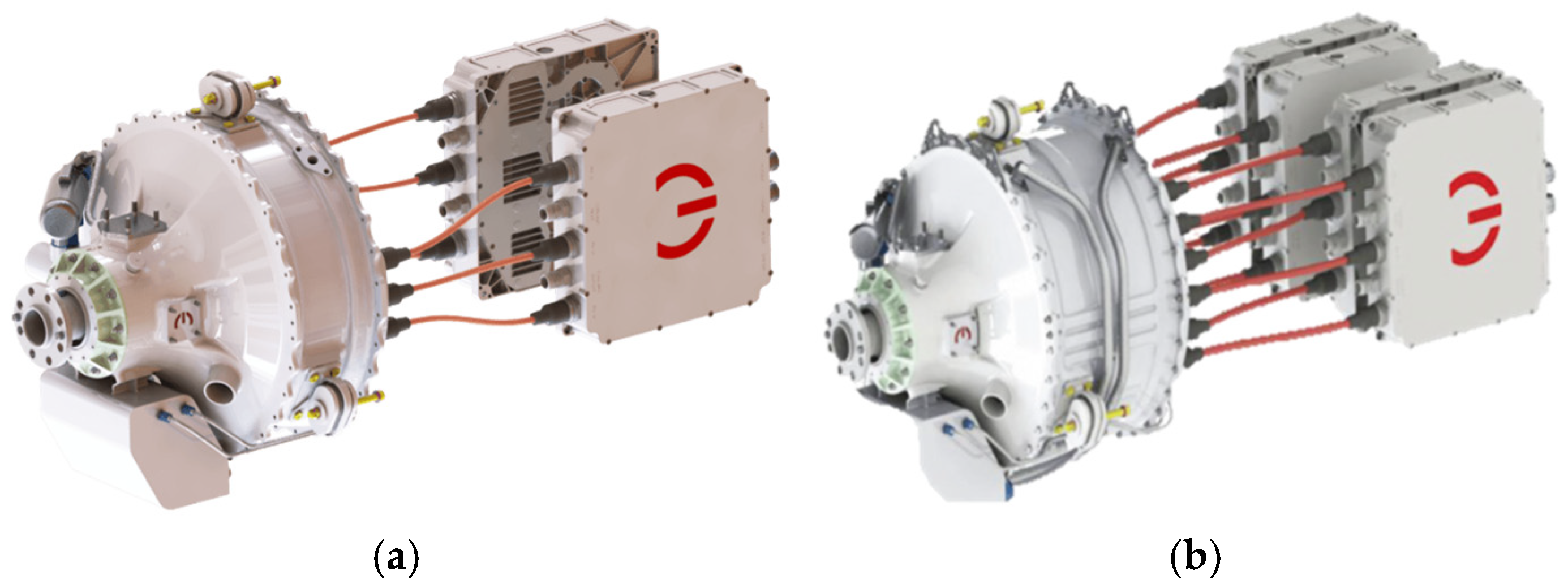
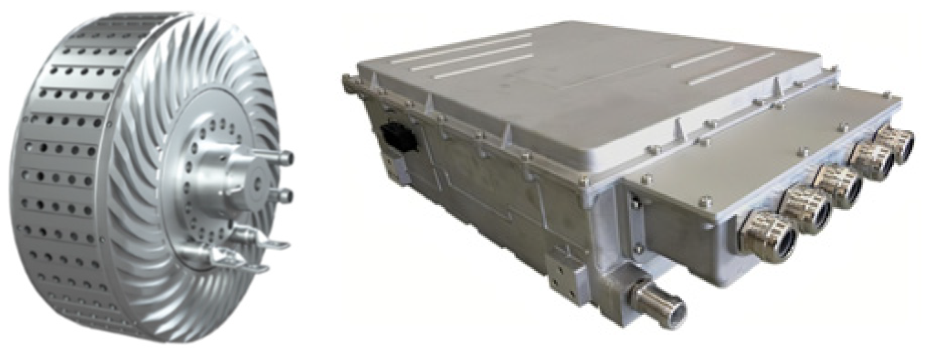
Engproc 80 00046 g001
Figure 2. Schematic of Magnix’s electric propulsion system, (a) magni250, (b) magni500.
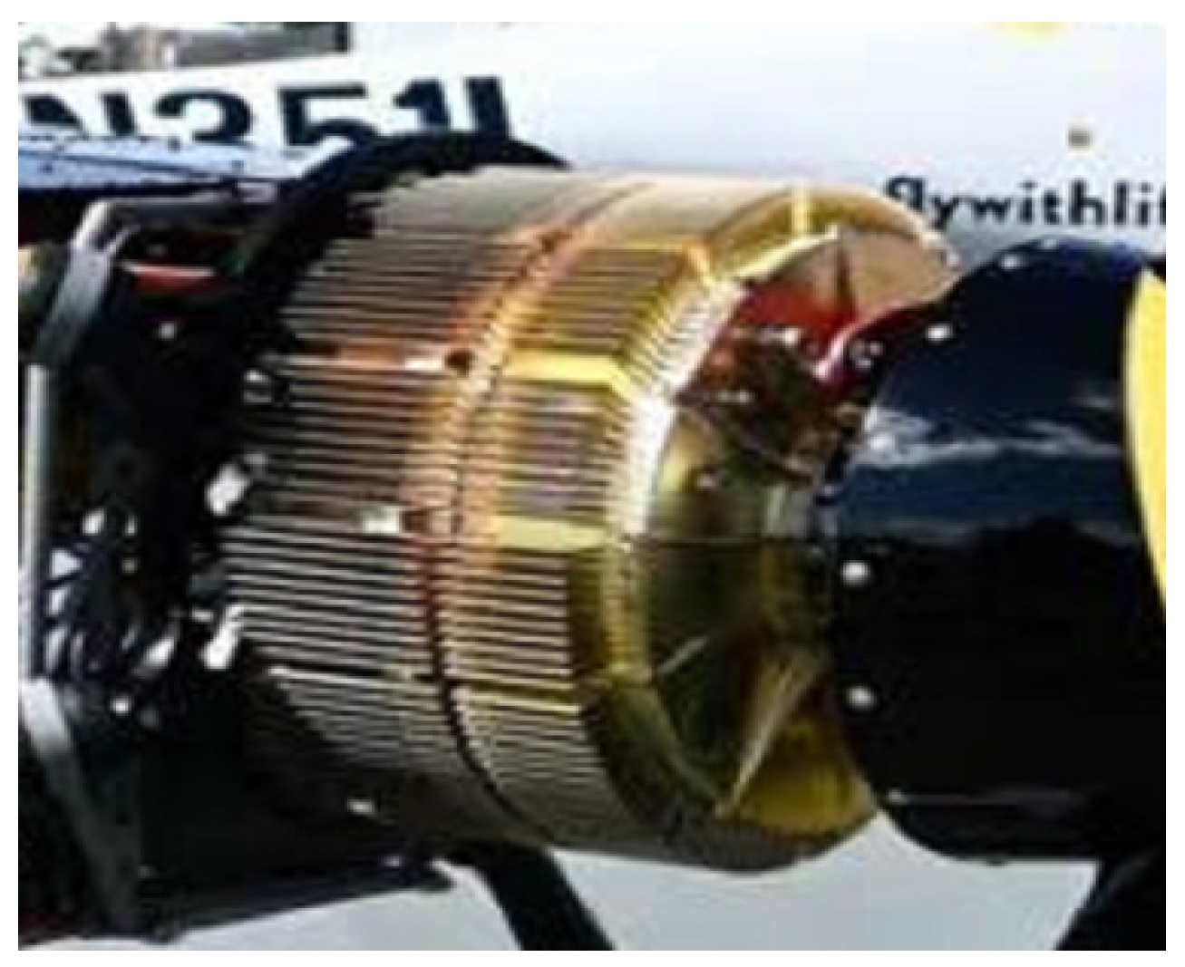
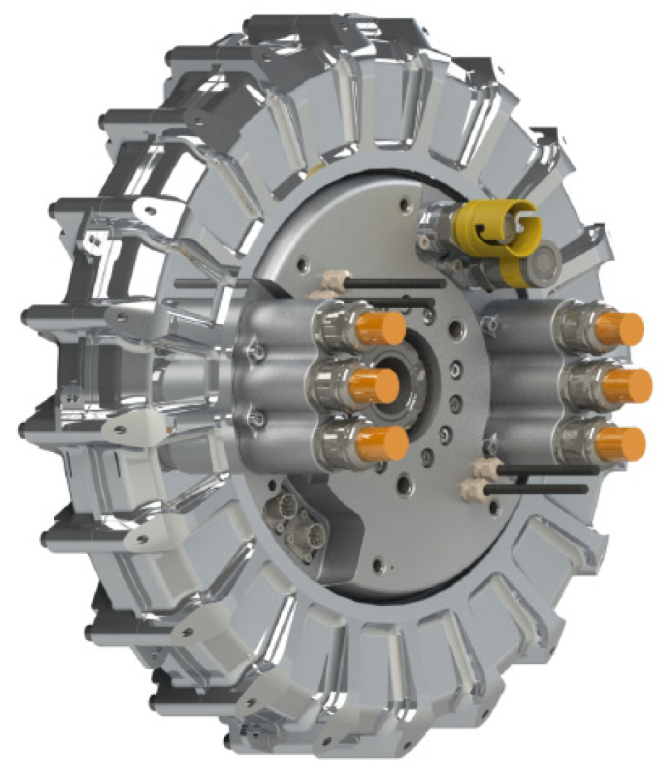
Engproc 80 00046 g002
Figure 3. Schematic diagram of Safran ENGINeUSTM electric propulsion.
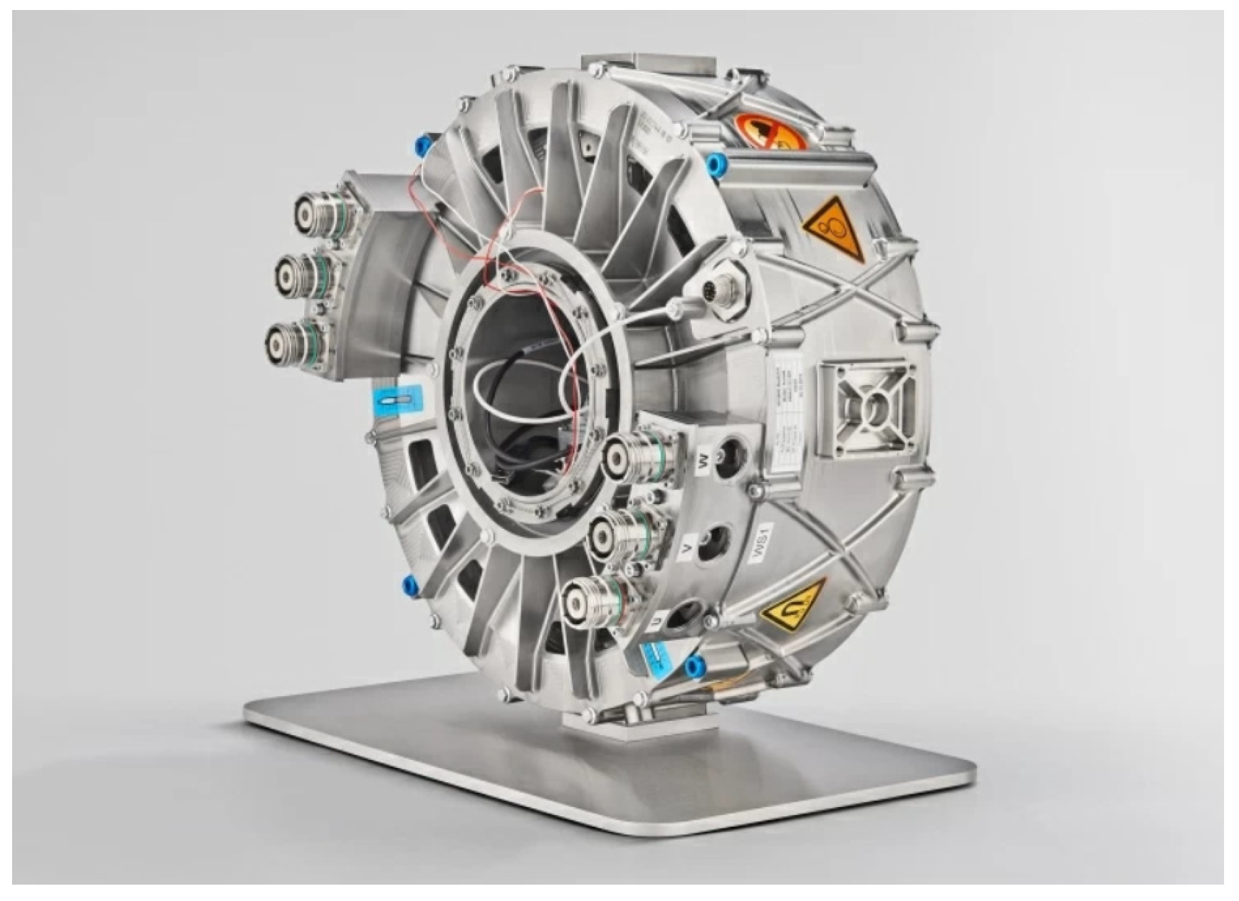
Engproc 80 00046 g003
Figure 4. SP260D motors from Siemens AG.
Engproc 80 00046 g004
Figure 5. Schematic diagram of HPDM series motors from H3X Corporation.
Engproc 80 00046 g005
Figure 6. Schematic of EMRAX specialized products.
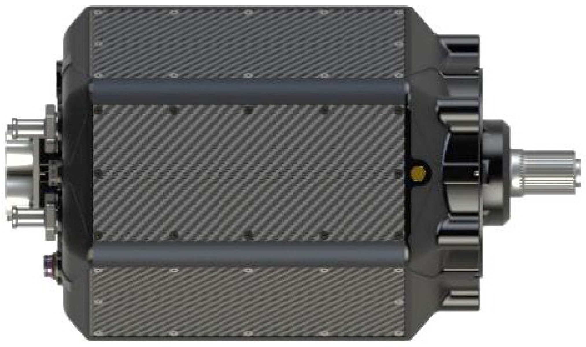
Engproc 80 00046 g006
Figure 7. Schematic diagram of D1500 axial flux motor.
Engproc 80 00046 g007
Figure 8. Schematic representation of the Tianjin SANTROLL product spectrum.
Engproc 80 00046 g008
Figure 9. Schematic diagram of Shandong Jingchuang motor and controller.
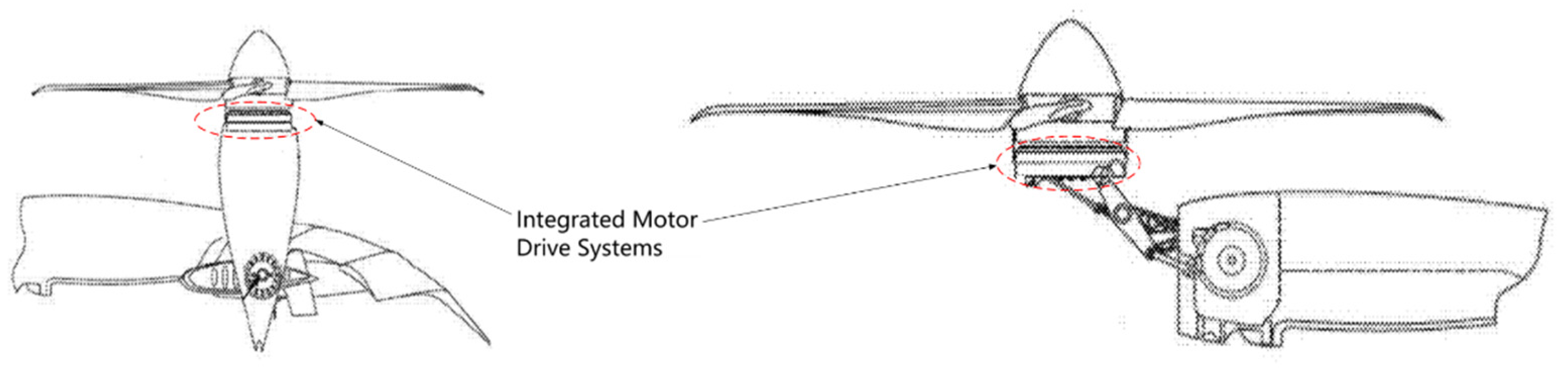
Engproc 80 00046 g009
Figure 10. Schematic diagram of Joby tilt-rotor mechanism.
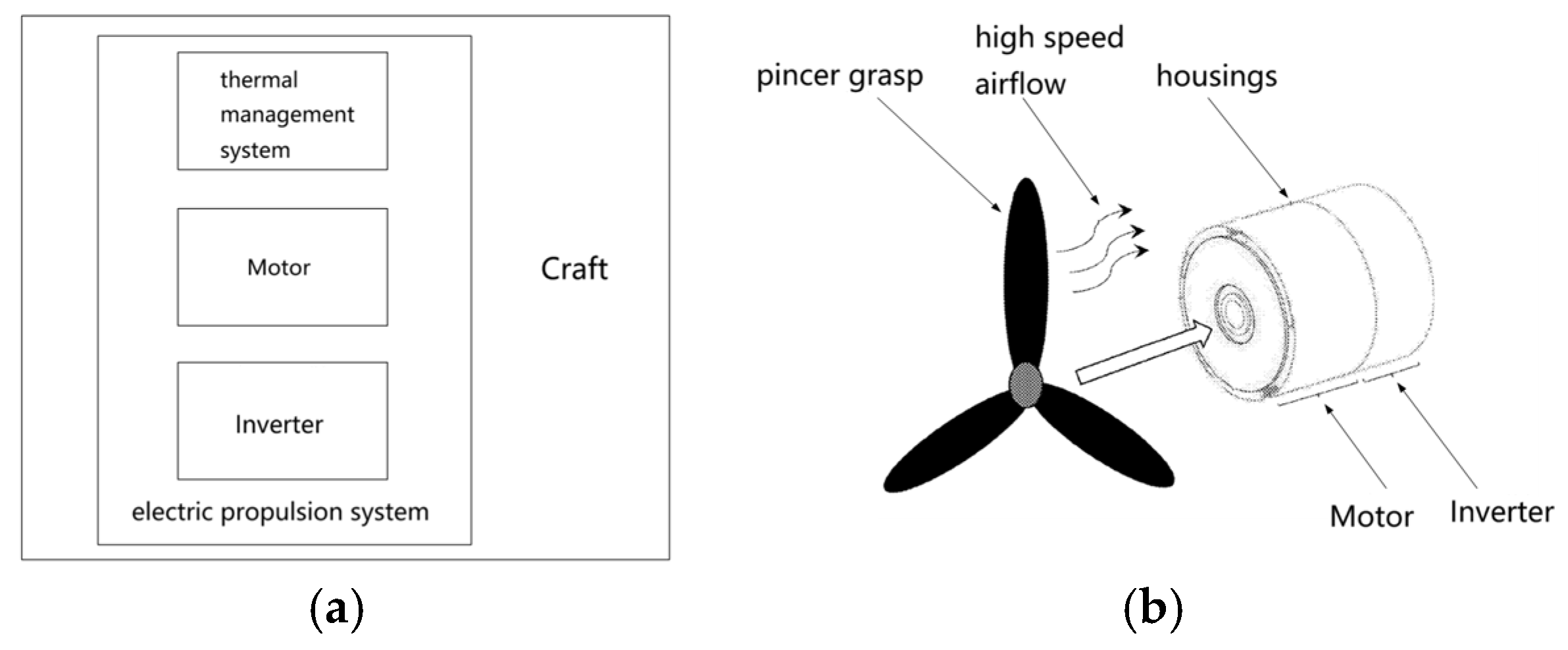
Engproc 80 00046 g010
Figure 11. Schematic diagram of the integrated motor drive system, (a) 3D model, (b) 2D model.
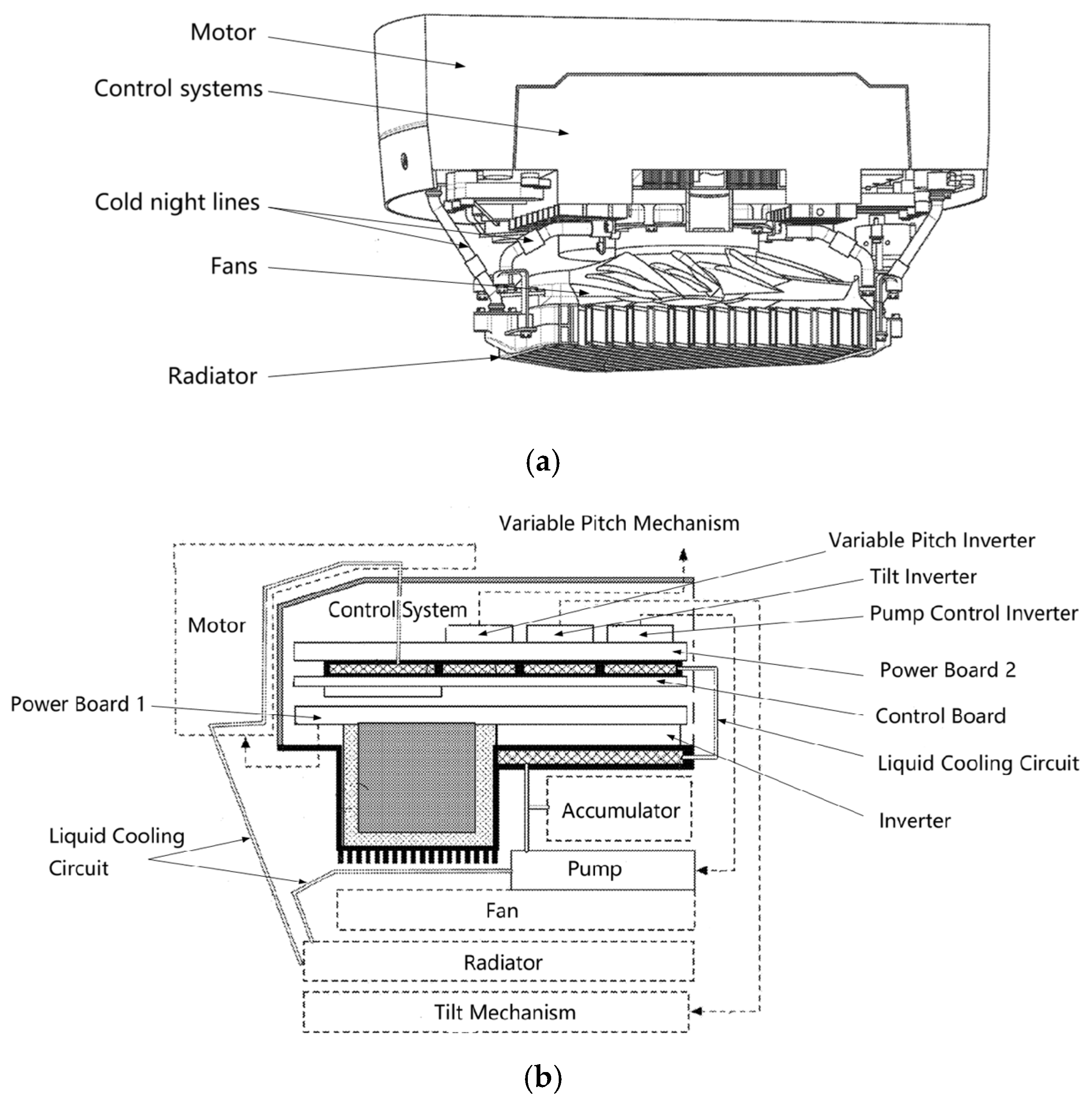
Engproc 80 00046 g011
Figure 12. Schematic of Honeywell’s electric propulsion system with integrated thermal management, (a) functional composition, (b) structure.
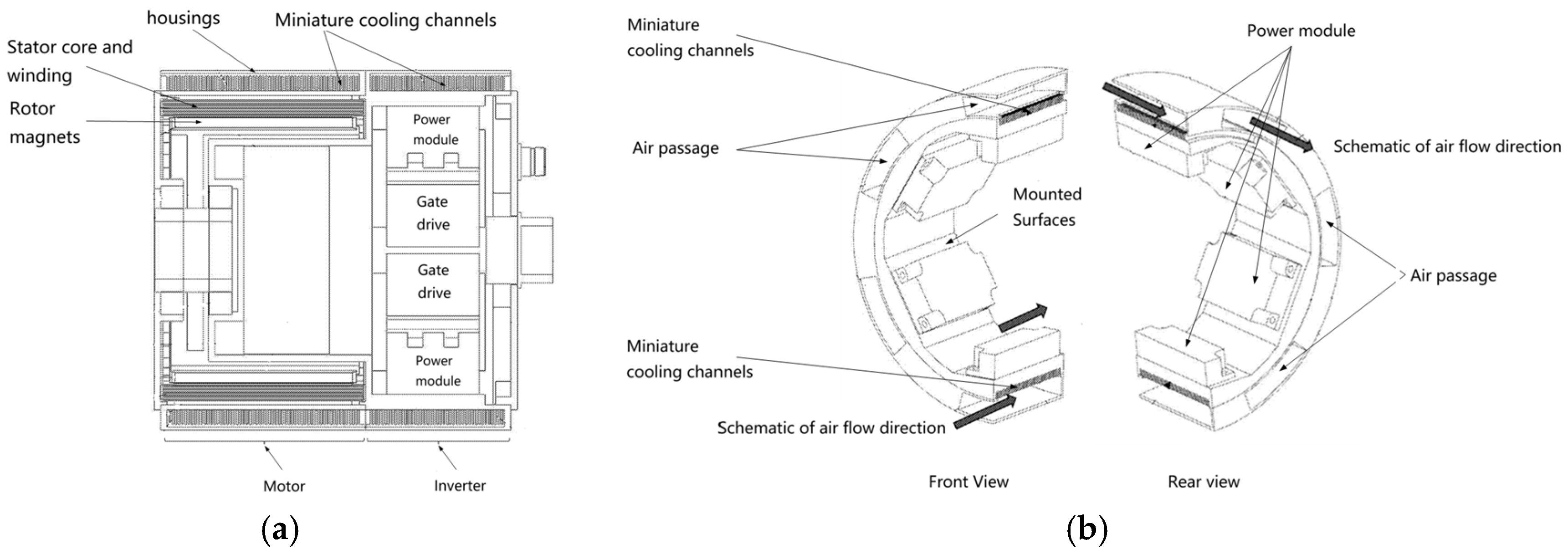
Engproc 80 00046 g012
Figure 13. Schematic diagram of the integrated structure of miniature heat dissipation channel, motor, and controller, (a) 2D model, (b) Power module air-cooling 3D model.
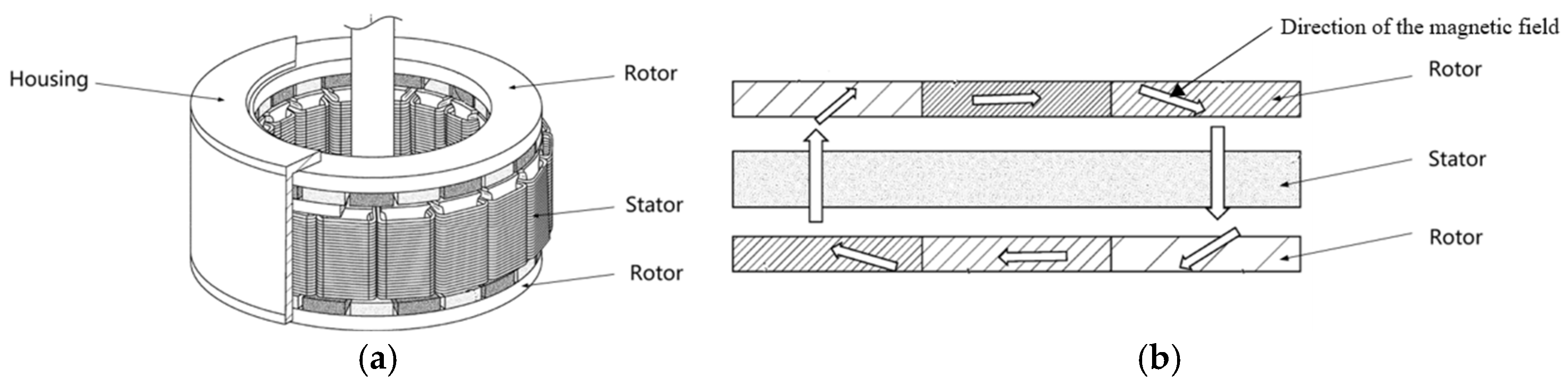
Engproc 80 00046 g013
Figure 14. Halbach polymagnetic axial field motors, (a) motor structure, (b) rotor Halbach polymagnetization.
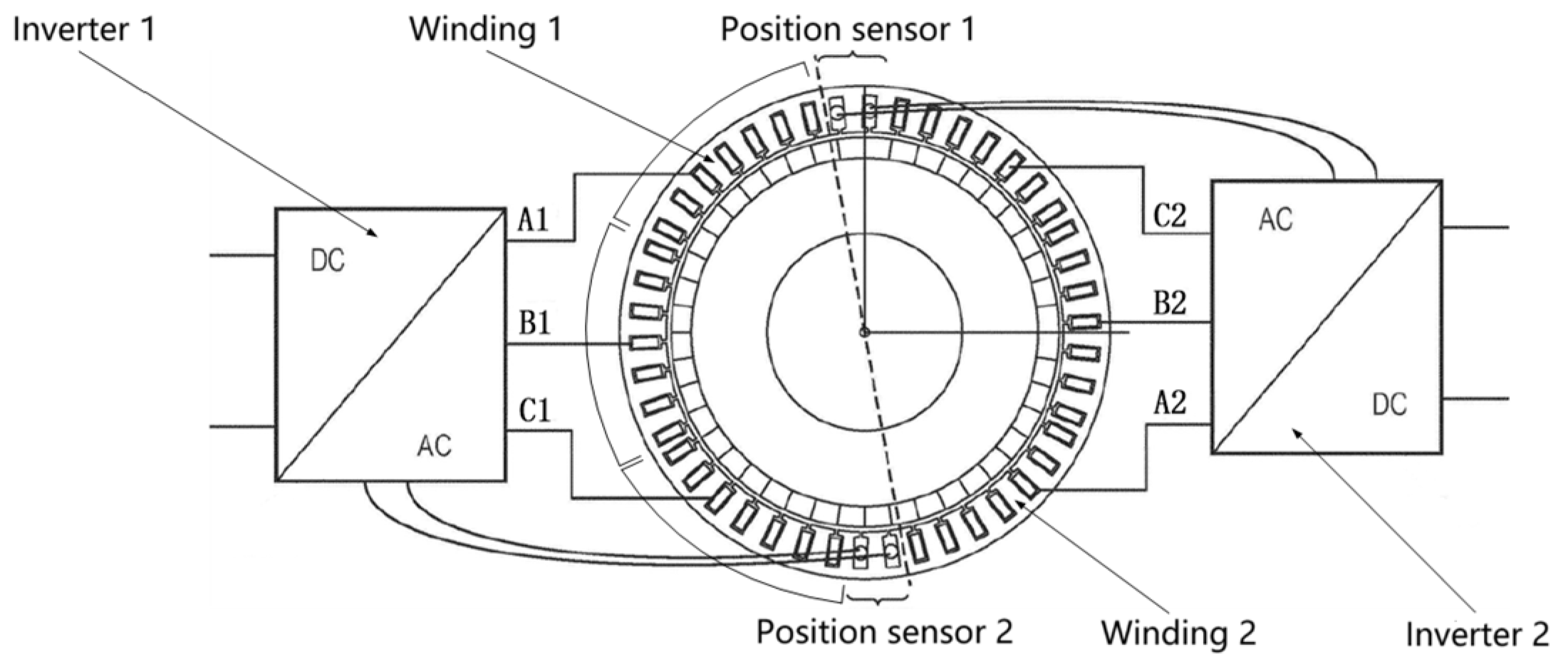
Engproc 80 00046 g014
Figure 15. Modular dual three-phase, dual position sensor motor structure.
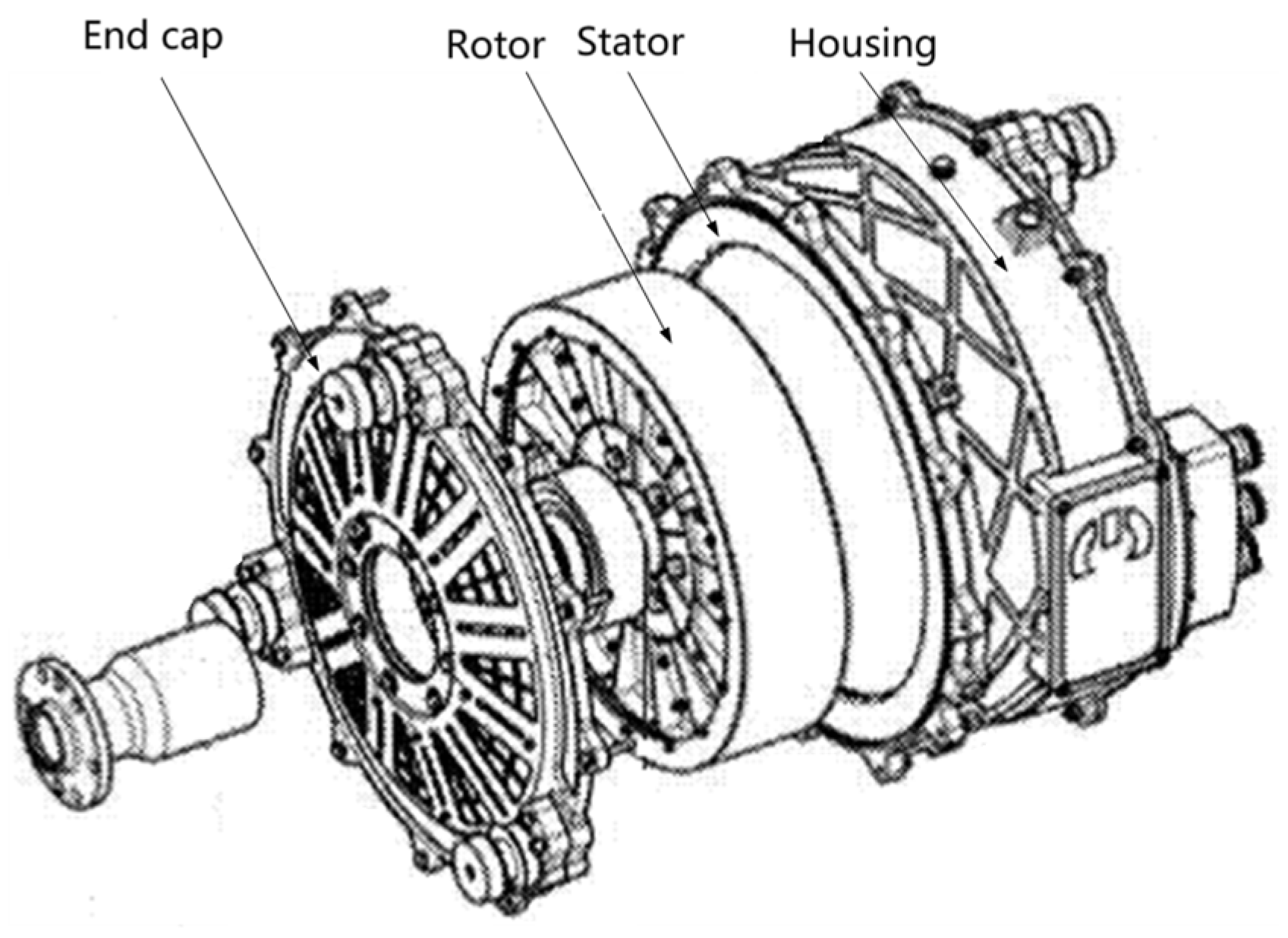
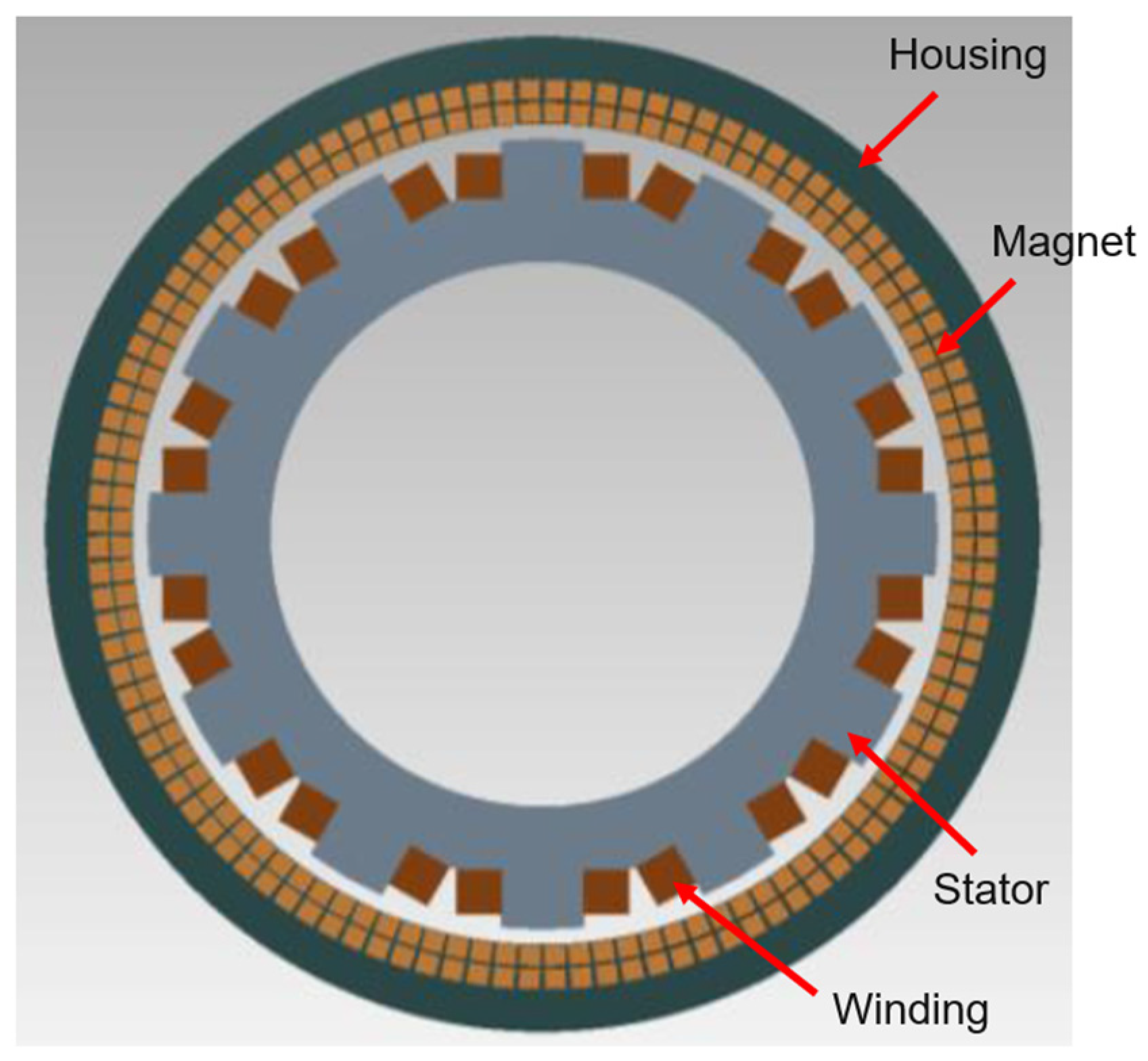
Engproc 80 00046 g015
Figure 16. Schematic construction of Magnix’s motor.
Engproc 80 00046 g016
Figure 17. Rotor structure of Magnix’s motors.
Engproc 80 00046 g017
Figure 18. Multi-layer cooling structure in the slot.
Engproc 80 00046 g018
Figure 19. Joby’s motors with integrated electrical busbar construction.
Engproc 80 00046 g019
Figure 20. Joby’s motors with in-slot cooling structure, (a) Radial, (b) Axial.
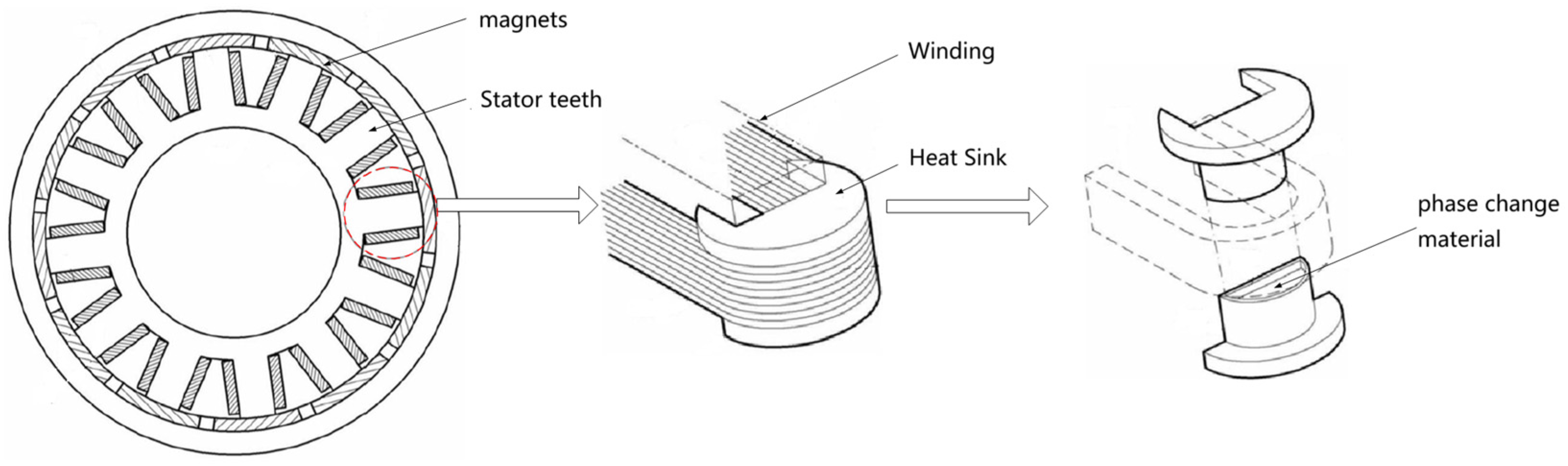
Engproc 80 00046 g020
Figure 21. Novel heat dissipation structure for winding ends based on phase change materials.
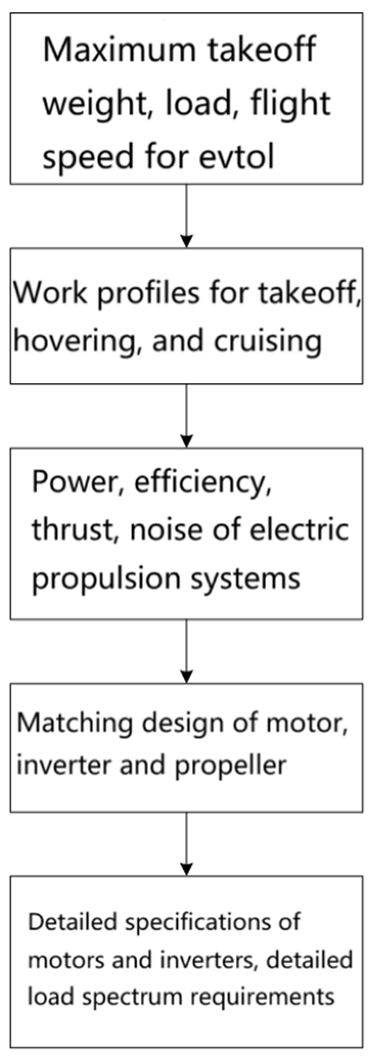
Engproc 80 00046 g021
Figure 22. Electric Propulsion Motor System Requirements Capture Process.
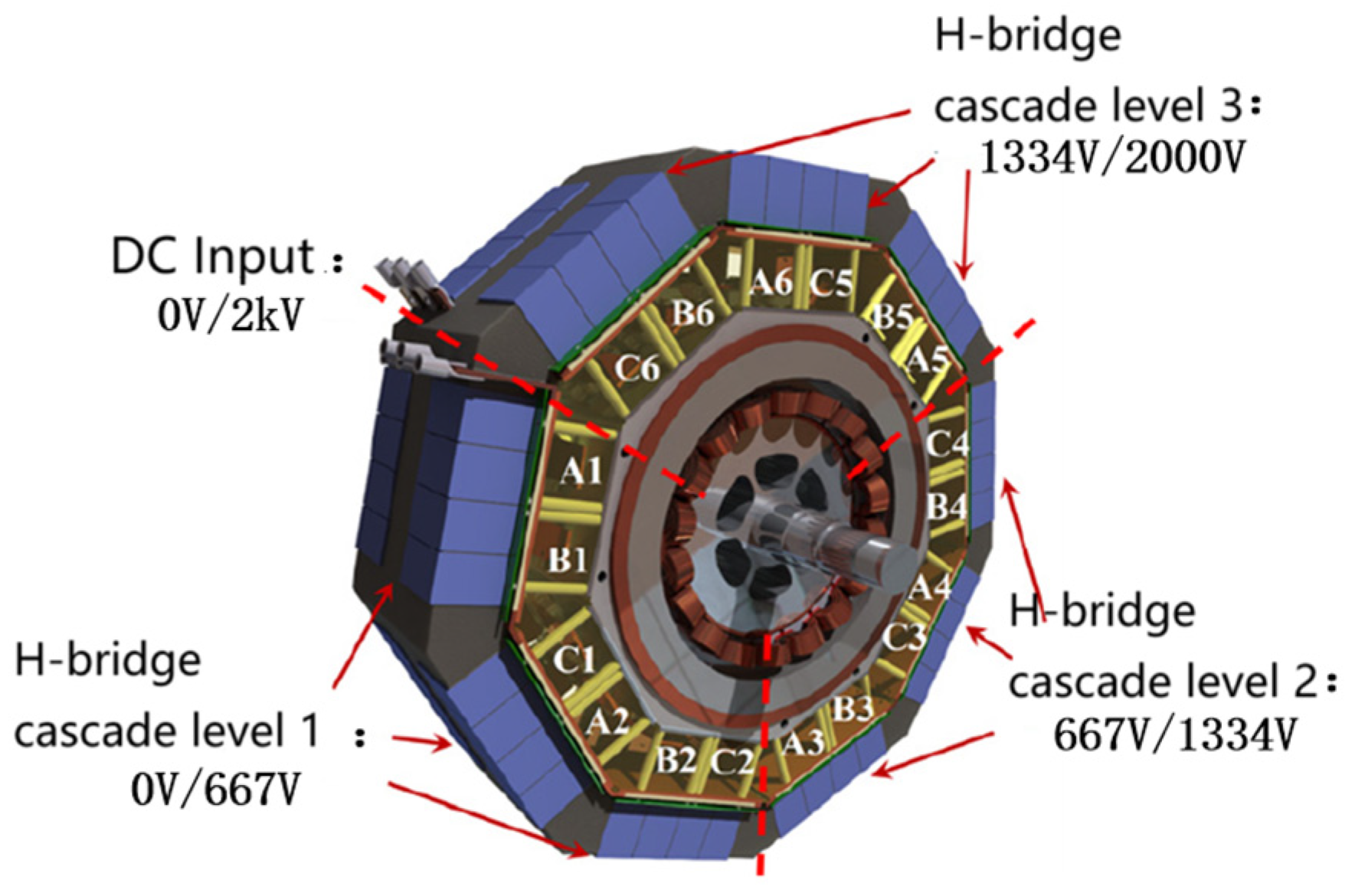
Engproc 80 00046 g022
Figure 23. 2 kV, 1 MW integrated modular motor system.
Engproc 80 00046 g023
Figure 24. Schematic diagram of the composition of a single stand-alone module.
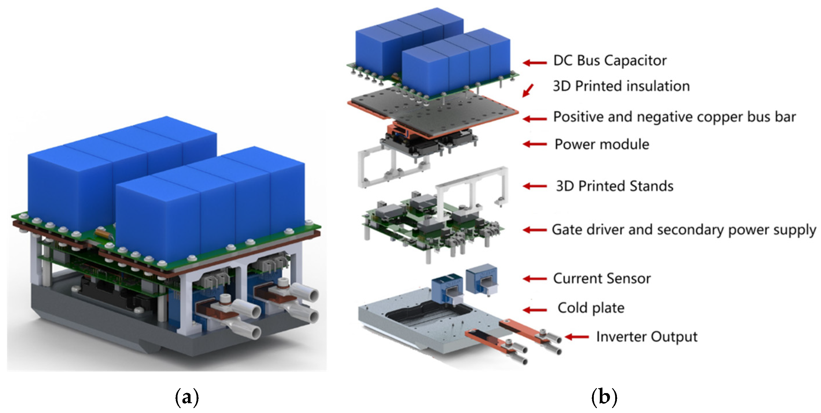
Engproc 80 00046 g024
Figure 25. Structure of an H-bridge inverter, (a) Entire machine, (b) Exploded View.
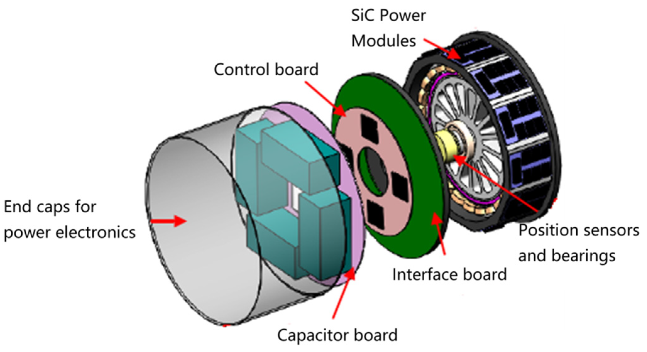
Engproc 80 00046 g025
Figure 26. Four-channel integrated, modular drive system.
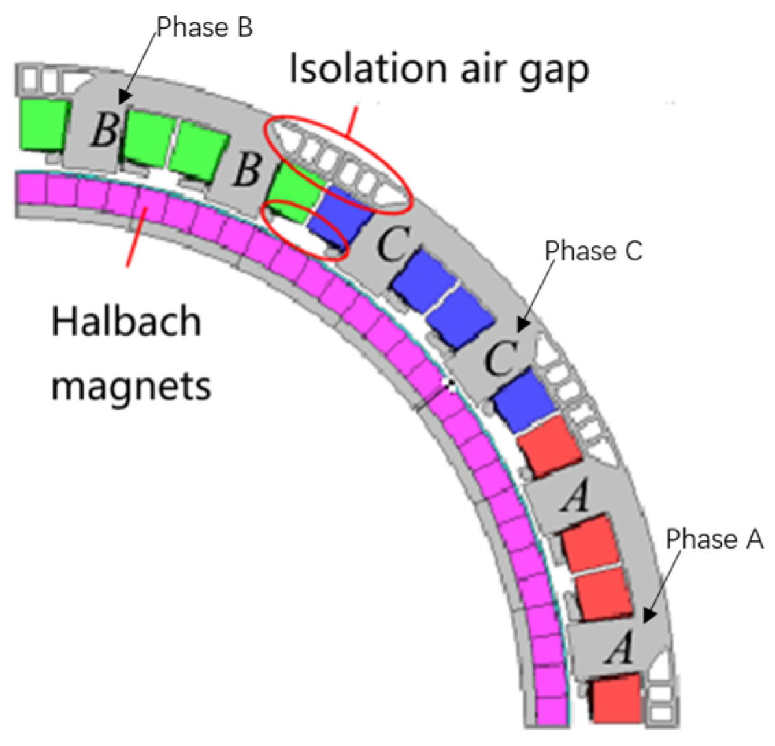
Engproc 80 00046 g026
Figure 27. 1/4 Circumference Module for Fault Tolerant Motors.
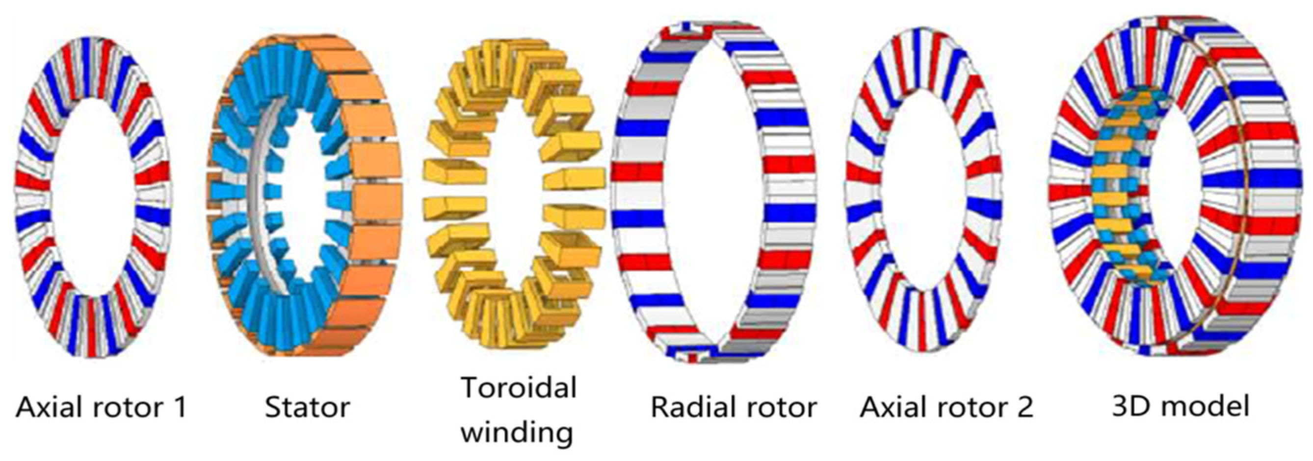
Engproc 80 00046 g027
Figure 28. Axial/radial hybrid magnetic field motors.
Engproc 80 00046 g028
Figure 29. 1.4 MW superconducting motor.
Engproc 80 00046 g029
Figure 30. Hollow wire schematic.
Engproc 80 00046 g030
Figure 31. 3D-printed coils from additive drives, (a) coils, (b) stator and winding.
Engproc 80 00046 g031
Figure 32. 3D-printed heat sink program design.
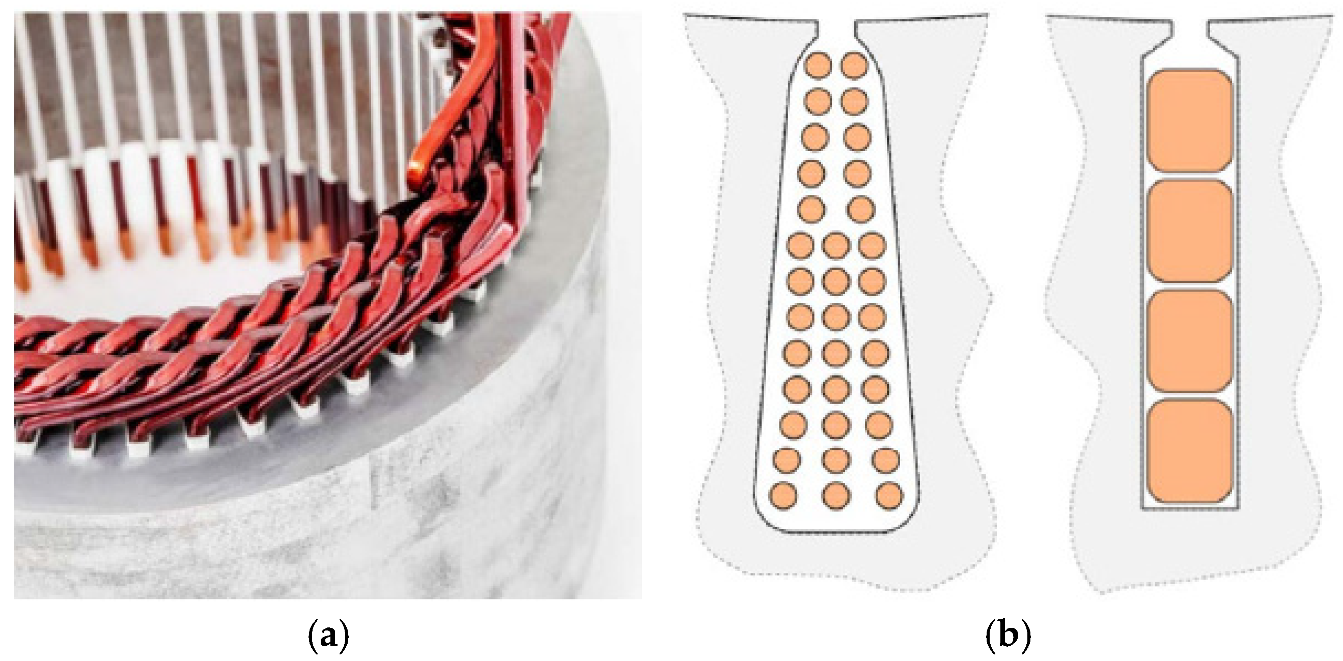
Engproc 80 00046 g032
Figure 33. Comparison of flat wire and round wire, (a) Flat wire stator, (b) Parallel tooth circular line (left) and parallel groove flat line (right).
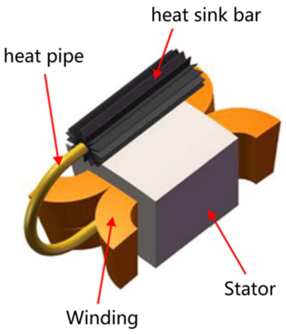
Engproc 80 00046 g033
Figure 34. Heat pipe cooling technology based on liquid-gas phase transition.
Engproc 80 00046 g034
Table 1. Parameters of Joby electric propulsion motors.
Technical IndicatorsValue
peak power [kW]236
peak torque [Nm]1800
rated torque [Nm]1380
weights [kg]28
rated torque density [Nm/kg]49
Table 2. Parameters of the magni500 propulsion motor.
Technical IndicatorsValue
Rated voltage [V]540
Voltage range [V]400–800
Rated power [kW]560@1900 rpm
Peak (take-off) power [kW]640
Rated torque [Nm]2814
Maximum speed [rpm]3000
Weights [kg]100–140
Efficiency [%]>93%
Number of three-phase winding sets4
Table 3. Parameters of HPDM-250 motor.
Technical IndicatorsValue (Direct Drive)Value (with Reducer)
Voltage range [V]300–900
Rated power [kW]200
Peak power [kW]250
Rated torque [Nm]95.5640
Peak torque [Nm]119.4800
Weight (without coolant) [kg]13.016.6
System efficiency(Takeoff) @200 kW93.4%92.2%
System efficiency(Cruise) @67 kW95.7%94.6%
Table 4. Parameters of the Emrax348 motor.
Technical IndicatorsValue (High Voltage)Value (Low Voltage)
Maximum voltage [V]800400
Rated power [kW]100200
Peak power [kW]190400
Rated torque [Nm]500
Peak torque [Nm]1000
Rated speed [rpm]18003800
Maximum speed [rpm]22004000
Weights [kg]40
Efficiency [%]92–98%
Table 5. Parameters of the D1500 motor.
Technical IndicatorsValue
Rated voltage [V]800
Maximum power (Cruise) [kW]280@1900 rpm
Peak power [kW]285@1800 rpm
Maximum torque(Cruise) [Nm]1400
Peak torque [Nm]1500
Maximum speed [rpm]2500
Weights [kg]≤40
Maximum Efficiency97%
Table 6. Parameters of Shandong Jingchuang motor.
Technical IndicatorsValue (JC-V270)Value (JC-V350)
Rated voltage [V]540/800800
Rated power [kW]64@3000 rpm90@2400 rpm
Rated torque [Nm]200360
Weights [kg]21.4–22.342.5–43.9
Rated torque density [Nm/kg]≥8.97≥8.2
Table 7. Design parameters of superconducting motors.
ParametersValue
Rated power [MW]1.4
Rated speed [rpm]6800
Rated voltage [V]1200
Rated current [A]360
Rated torque density [Nm/kg]≥8.97
Table 8. Effect of different cooling methods on winding current density.
Cooling MethodMaximum Current Density [A/mm2]
Natural convection1.5–5
Forced radial/axial air cooling5–12
Water-cooling of housings10–25
Slot cooling12–33
Spray and drip oil cooling15–30
Hollow wire15–50
Oil immersion cooling15–90
Disclaimer/Publisher’s Note: The statements, opinions and data contained in all publications are solely those of the individual author(s) and contributor(s) and not of MDPI and/or the editor(s). MDPI and/or the editor(s) disclaim responsibility for any injury to people or property resulting from any ideas, methods, instructions or products referred to in the content.

