Abstract
This work presents a new sliding mode control strategy that integrates a Clegg integrator into a Proportional Integral Derivative (PID) sliding surface to address controller saturation (windup) and chattering. The proposed controller was implemented on a Programmable Logic Controller (PLC) to regulate the speed of a three-phase induction motor using a frequency inverter as the final control element. Conventional PID and sliding mode controllers (SMCs) were also implemented for performance comparison. This study included tests for sudden set-point changes and disturbances to evaluate the control strategies. The proposed controller demonstrated a faster response compared to the PID control and a smoother control action compared to the SMC. The results and conclusions discuss the advantages and limitations of the proposed control strategy in comparison to the conventional methods.
1. Introduction
In control systems, Proportional-Integral-Derivative (PID) controllers have been widely used for decades due to their simplicity and effectiveness in a variety of industrial applications. Their ability to combine proportional, integral, and derivative actions allows for a balanced response that theoretically provides stability and precision. However, PID controllers have significant limitations, particularly in systems with nonlinear dynamics or varying operating conditions. Their performance can degrade due to issues like instability, overshoot, and sustained oscillations [1,2]. Despite their advantages in linear systems, PIDs struggle with nonlinearities such as saturation, and their performance can become unstable in fast systems [3].
To address these limitations, various control structures have been proposed, including adaptive gains [4], online tuning [5], and controllers with anti-windup actions [6,7]. Among the robust alternatives, the Sliding Mode Controller (SMC) is notable for its ability to handle disturbances and complex dynamics [8,9]. However, SMCs are prone to “chattering”, a phenomenon of high-frequency oscillations that can reduce actuator lifespan [10]. Techniques like replacing the sign function with a sigmoid function can mitigate chattering, but this approach can introduce issues like wind-up and reduced controller speed [11].
Wind-up occurs when the integral action accumulates excess control effort due to the controller’s output needing to reduce its magnitude, which leads to overshoot and prolonged settling times [12]. Various methods, such as neural networks [4] and fractional-order PID controllers [13], address wind-up but add complexity to controller design.
This work introduces a new sliding control approach using a Clegg integrator on a PID-type sliding surface to mitigate integral windup and chattering. The Clegg integrator reduces saturation effects by resetting the integral action when the error crosses zero, improving control precision and response speed [14]. The proposed approach will be evaluated through a closed-loop velocity control system implemented on a half-horsepower, three-phase motor. The controller was implemented in a Modicon M580 PLC that acts over a variable frequency drive. For comparison purposes, the proposed SMC control is assessed alongside a traditional PID controller, aiming to offer smoother control actions and enhanced actuator longevity.
2. Methodology
The Sliding Mode Controller (SMC) with a Clegg Integrator introduces a robust control strategy capable of handling systems with nonlinearities and uncertainties. The SMC provides robustness by driving the system’s state to a predefined sliding surface and maintaining it there despite disturbances. Integrating the Clegg integrator, known for its reset mechanism that reduces overshoot and improves transient response, enhances the performance of the SMC. This combination effectively mitigates chattering, a common issue in conventional SMCs, and optimizes system response, making it a valuable approach in control systems where precision and robustness are critical. The following sections present details about the system identification and controller design for a velocity control application.
2.1. System Description and Identification
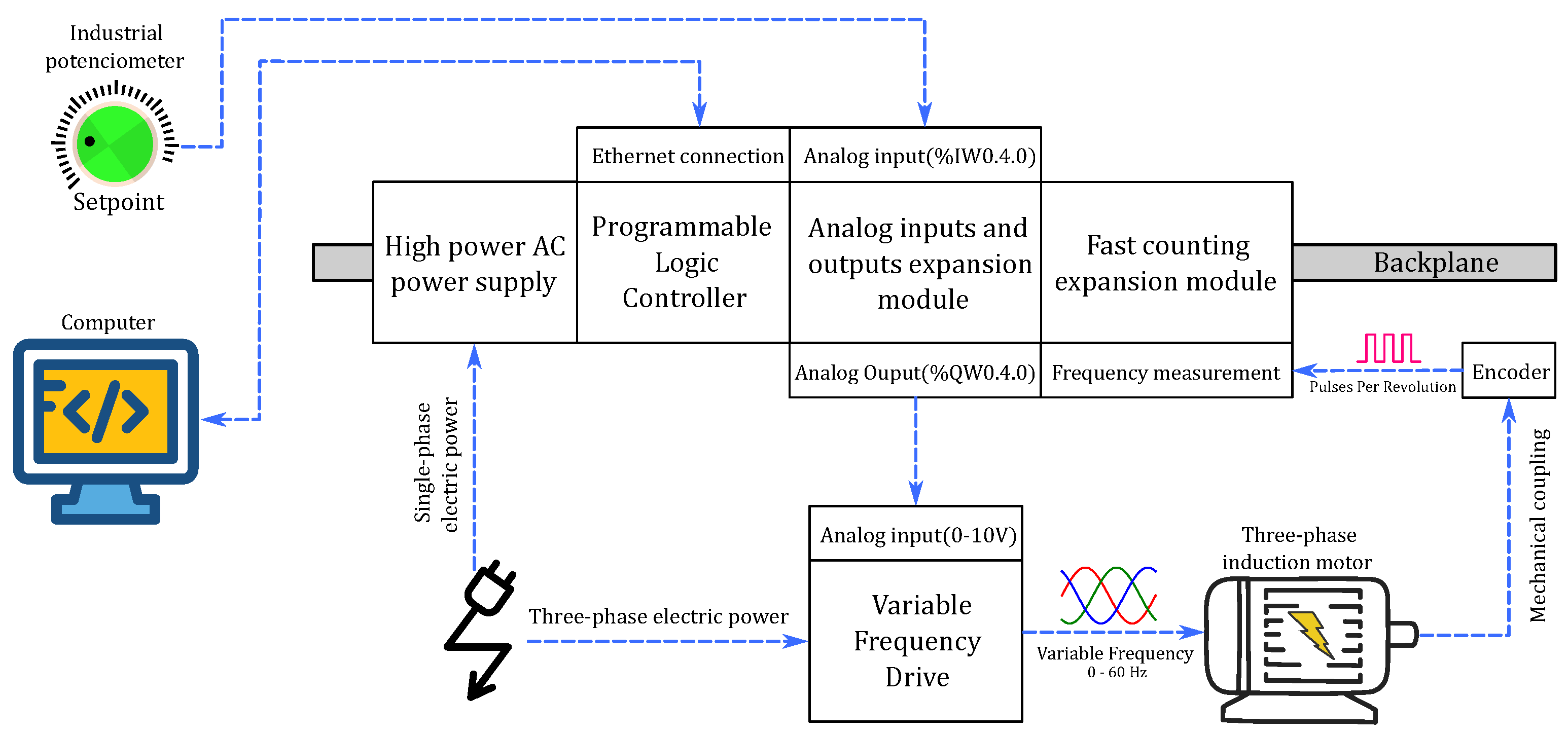
The control system consists of a three-phase induction motor driven by a frequency inverter with feedback from an encoder. A Schneider Electric Modicon M580 PLC is responsible for managing the process control. The test bench, depicted in Figure 1, includes the M580 PLC connected to expansion modules for analog inputs/outputs and fast counting driver, all integrated via a backplane to evaluate the controllers’ performance.
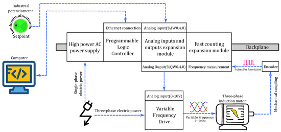
Figure 1.
Schematic of implemented system.
The speed setpoint is given by an analog input on the expansion module, and an analog output generates a 0 to 10 V signal to control the variable frequency drive to adjust the motor speed. An encoder, attached to the motor shaft, provides pulse counts per revolution to the fast counting module in frequency mode, which is then used to calculate the motor’s speed in revolutions-per-minute (RPM).
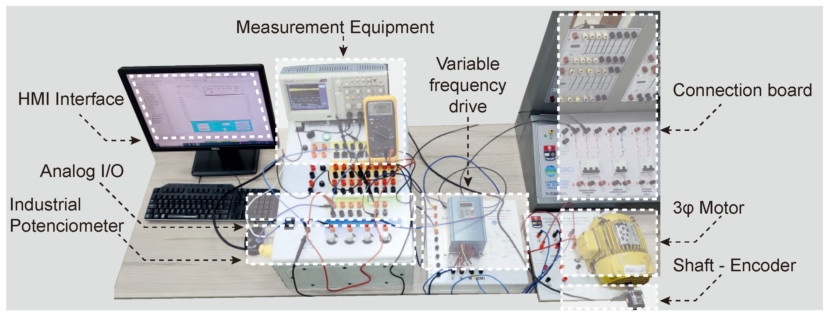
The control setup used for testing and comparing the controllers is shown in Figure 2. The main components, including the frequency drive, motor, encoder, and PLC, are highlighted. The PLC is housed in a protective case with external output connectors.
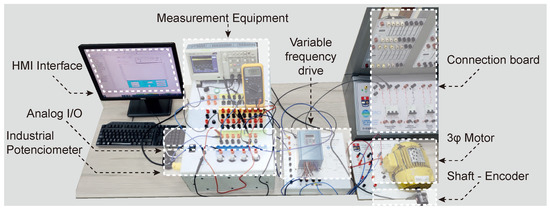
Figure 2.
Plant implemented to test the designed controllers.
Model Approximation
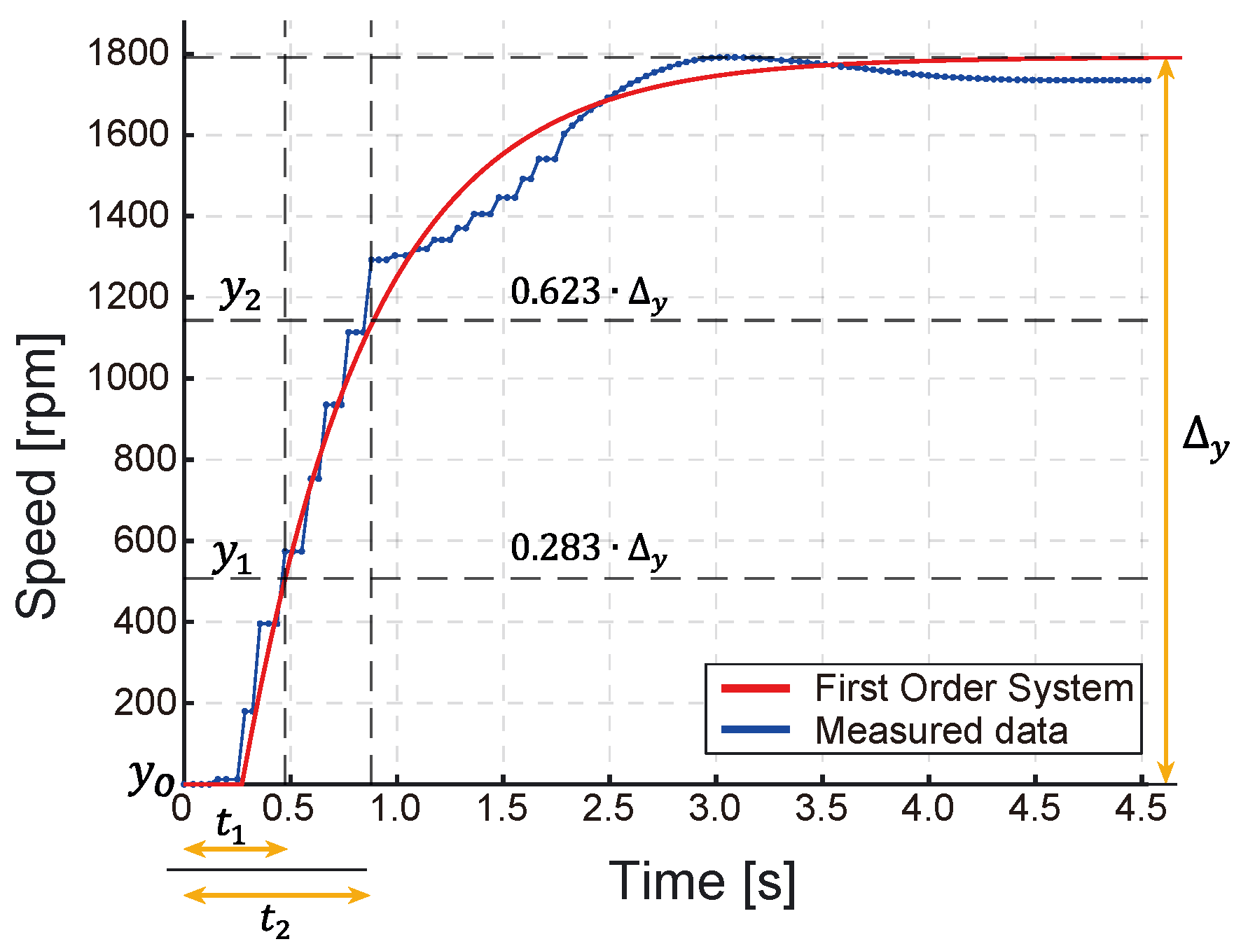
Industrial processes often exhibit nonlinear behavior or are modeled by high-order equations, complicating controller design. Approximation techniques simplify by deriving a linear model that retains the key traits of the nonlinear process. One widely used approximation is the First Order Plus Dead Time (FOPDT) model, derived by applying a step input, measuring the output, and extracting ’Smith points’ from the reaction curve [15]. This allows the nonlinear process to be effectively approximated by the FOPDT model, as shown in (1).
where is the controlled variable, is the output variable, K is the steady-state gain, is the system delay, and is the system time constant. The steady-state gain K is determined by , the system delay time is found using , and the time constant is given by . The “Smith two-point method” [15] is used to identify and , the times at which the output reaches 28.3% and 63.2% of its final value, respectively.
The system’s response, depicted in Figure 3, highlights nonlinearities that challenge controller development. For comparison, the response of the first-order model with delay to the same step input was simulated allowing a visual assessment alongside the measured data.
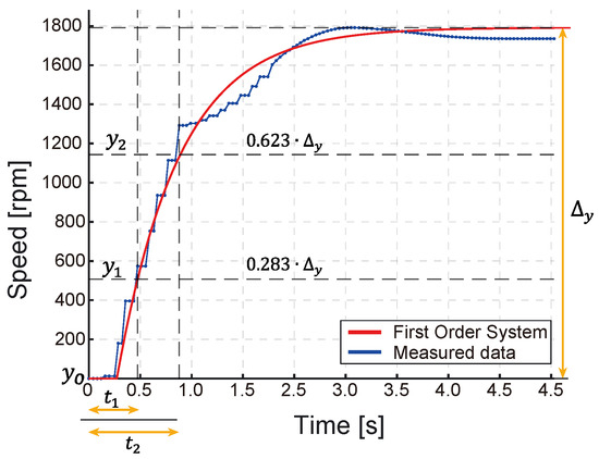
Figure 3.
Response to a step input.
2.2. Fundamental Aspects of the Controllers
2.2.1. Proportional Integral Derivative Controller (PID)
PID controllers are the most commonly used feedback controllers, with over 90% of control loops employing them, primarily in PI form due to the rare use of derivative action [16]. Their widespread use stems from their simplicity and effectiveness. Designing a PID controller involves identifying the process model, designing the controller structure, and tuning the parameters [17]. In this case, the classical PID structure, as shown in Equation (2), will be utilized.
where is the controller output, is the system error, which is the difference between the setpoint and the motor’s speed. is the integral action time constant, and is the derivative action time constant.
2.2.2. Sliding Mode Controller (SMC)
The Sliding Mode Controller (SMC) is a robust, nonlinear controller designed to handle modeling inaccuracies by driving the system state to and maintaining it on a predefined sliding surface [18].
The sliding surface use in this work is defined as:
where and are tuning constants.
SMC consists of two main components: a discontinuous part, , which moves the system quickly towards the sliding surface, and a continuous part, , which keeps the system on the surface and guides it to the desired state [18]. The SMC control equation is given by (4). The Sliding Mode Controller (SMC) described in [19] was used as a basis for the development of the proposed controller. The following key equations are presented:
The continuous component is derived from the sliding surface (4) and the system model approximation (1), as follows:
The discontinuous component is given by
where , , , and are constants used in the controller design. The constants and are associated with the sliding surface dynamics, is a gain factor for the discontinuous part, and is a small positive constant to avoid division by zero. The method for calculating these constants is proposed in [19].
2.3. Control Proposal: SMC+CLEGG Integrator
Chattering and high are common issues in SMC due to its discontinuous control nature. Using a Clegg integrator (CI) can reduce these problems by providing smoother control and minimizing high-frequency oscillations.
The Clegg integrator, introduced by Clegg [20], is a nonlinear integrator with a reset action. It was further developed by Krishnan and Horowitz and generalized as FORE by Horowitz and Rosenbaum [21]. The CI resets its state to zero when the input crosses zero.
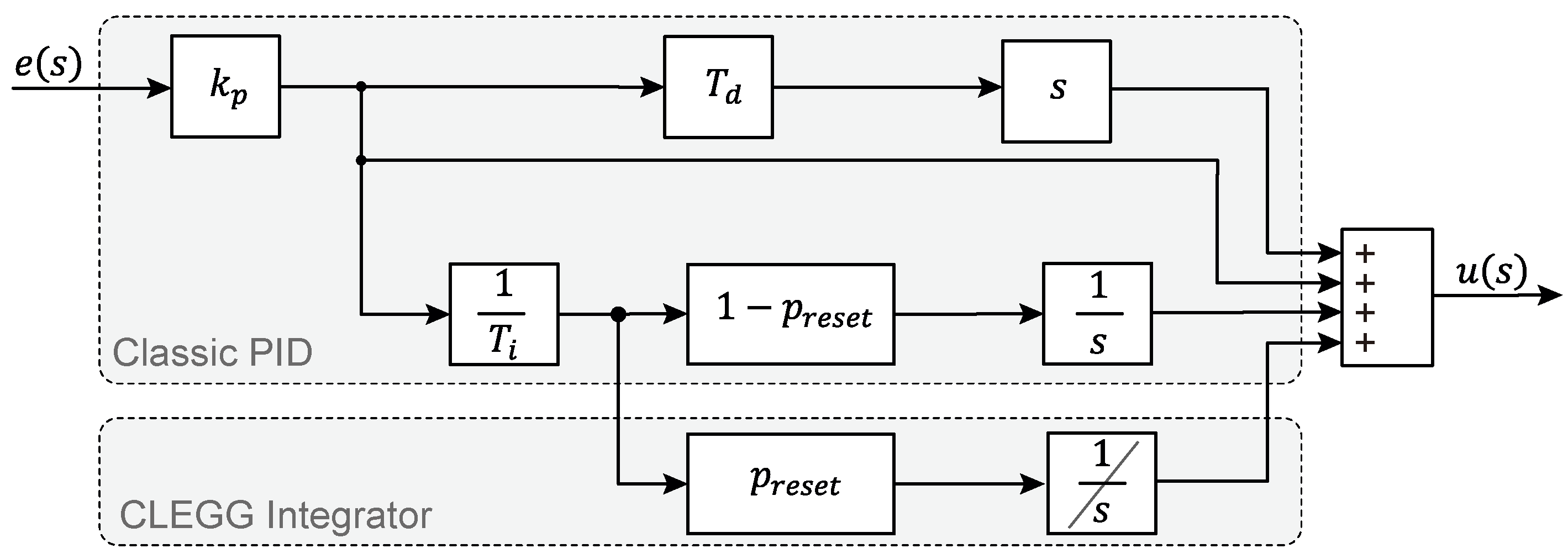
The PID+CI controller, shown in Figure 4, is a nonlinear/hybrid PID controller that maintains the characteristics of traditional PID controller. Its input is the error signal , the output is the control signal , is the proportional gain, is the derivative constant, and is the integral time constant [14].
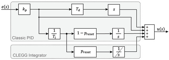
Figure 4.
Structure of the PID+CI controller.
The parameter , or reset ratio, is a dimensionless constant with values that adjusts the weight of the term relative to the I term. A controller becomes a controller if the reset action is removed () and a controller if . The reset should not apply to the entire integral term to preserve its fundamental asymptotic property [14].
The control scheme is described in (7), as follows:
The reset action is indicated in (7) by setting when crosses zero. Recall that the operator denotes the CLEGG integrator.
The reset action impacts only the discontinuous component of the controller, as the control law for the continuous component requires the derivative of the sliding surface, thereby excluding the Clegg integrator. Conversely, the discontinuous component uses the sliding surface in both the numerator and denominator of its equation.
The objective of the proposed approach is to reduce the significant overshoot and chattering, which are primarily caused by the discontinuous part of the controller.
The final control equation is presented in (9), as follows:
2.4. Evaluation Methods
To assess the efficacy of the controller and to juxtapose its performance with alternative control methodologies, the following indices will be employed [14]:
- Maximum overshoot (): Evaluates the overshoot of the controlled variable, indicating the speed at which the control action can change or vary.
- Rise time (): Measures how quickly the controller pushes the controlled variable towards the reference.
- Settling time (): Determines the time required for the control action to stabilize the controlled variable within a 2% margin.
- Integral index of absolute error (IAE): Assesses the controller’s performance by comparing the controlled variable with the reference; in this study, it is used to identify which controller more effectively ensures that the system follows the reference.
- Total variations in control efforts (TVu): Evaluates the strength of the control action, used here to compare the smoothness of different control strategies.
3. Implementation and Results
3.1. Implementation Details
The control assessment was carried out in the experimental setup displayed in Figure 2 where the controllers were implemented in the Modicon PLC. The control strategies evaluated were a PID controller, a sliding mode controller (SMC), and a combined SMC with a Clegg integrator. The controlled variable is the motor speed, which is handled by a frequency drive system.
To conduct a thorough and precise assessment of the system, two categories of tests were executed:
- Sudden changes in the set point: Sudden modifications in the speed set point were applied to examine the system’s capability to respond and adjust promptly to the newly established conditions. Also, sudden set point decreases, analogous to abrupt changes, and a swift reduction in the speed set point was initiated. This facilitated the evaluation of the system’s stability and its proficiency in managing deceleration events.
- Disturbances: A significant perturbation was introduced into the coupler connecting the encoder and the motor to assess the resilience of the system. This disturbance was simulated in the PLC by introducing a step change in the feedback from the encoder. This evaluation seeks to determine whether the system can sustain the desired set-point speed, even amidst external interferences or physical disturbances that may compromise its operational efficacy.
The Software Matlab R2022b was used to obtain the system model, calculate the performance indices, and compare the results. For PLC programming and data acquisition, Control Expert version 15, with a Python add-on for MODBUS communication, was utilized.
3.2. Sudden Changes in the Set Point
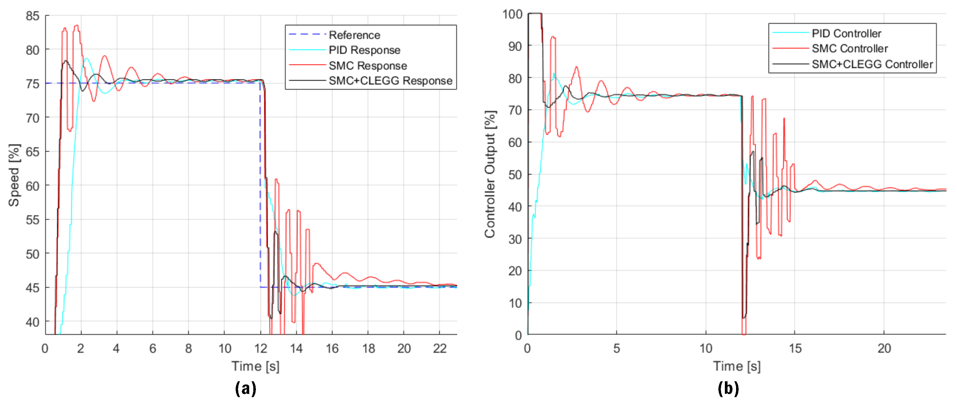
Figure 5 illustrates the speed response to sudden positive and negative changes, as well as the controller’s output in reaction to abrupt set-point modifications.
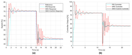
Figure 5.
Results of a sudden set-point change test. (a) Speed of the three-phase motor, (b) controller output sent to the frequency variator.
Table 1 presents the performance indices observed during this test, along with the percentage improvement of the proposed approach compared to conventional PID and SMC controllers.

Table 1.
Test results for different controllers: sudden changes in the set point.
Figure 5a shows the results obtained for sudden set-point changes, both positive and negative, which show clear differences in the performance of the evaluated controllers. In positive changes, the SMC+Clegg controller proves to be the most effective, with overshoot reduced to 4.40% and the shortest settling time of 1.599 s, indicating fast convergence to the desired set point with greater stability compared to PID and SMC. While the PID shows a longer rise time (1.934 s) and a larger overshoot (10.80%), the SMC is characterized by steeper oscillations before stabilizing. This is reflected in the significant percentage improvements in response times for SMC+Clegg, positioning it as the fastest and most accurate option in scenarios with positive set-point changes.
For the negative changes, the SMC+Clegg once again demonstrates its superiority by offering shorter settling times and a better response to the chattering phenomenon. Although the PID has a shorter decay time (1.558 s), this benefit is overshadowed by its greater negative overshoot and lower overall stability. The SMC+Clegg, with a decay time reduced to 0.438 s, ensures fast adaptation without compromising stability, while the SMC struggles with oscillations and long settling times. These quantitative results reinforce that SMC+Clegg offers a better balance between response speed and robustness, making it suitable for applications that require high precision and stability against disturbances and sudden changes.
Figure 5b shows the control signal; the SMC+Clegg controller effectively minimizes oscillations and achieves the lowest IAE value (2409.30), indicating its superior ability to reduce accumulated error over time. However, while it demonstrates efficiency in maintaining precision, it is important to note that the PID controller achieves a lower TVu value (1825.74), suggesting that PID requires less overall control effort. Despite this, the SMC+Clegg controller strikes a more effective balance between precision and response speed, making it a robust choice for applications demanding high accuracy and stability in the presence of abrupt set-point changes.
3.3. Disturbance Testing
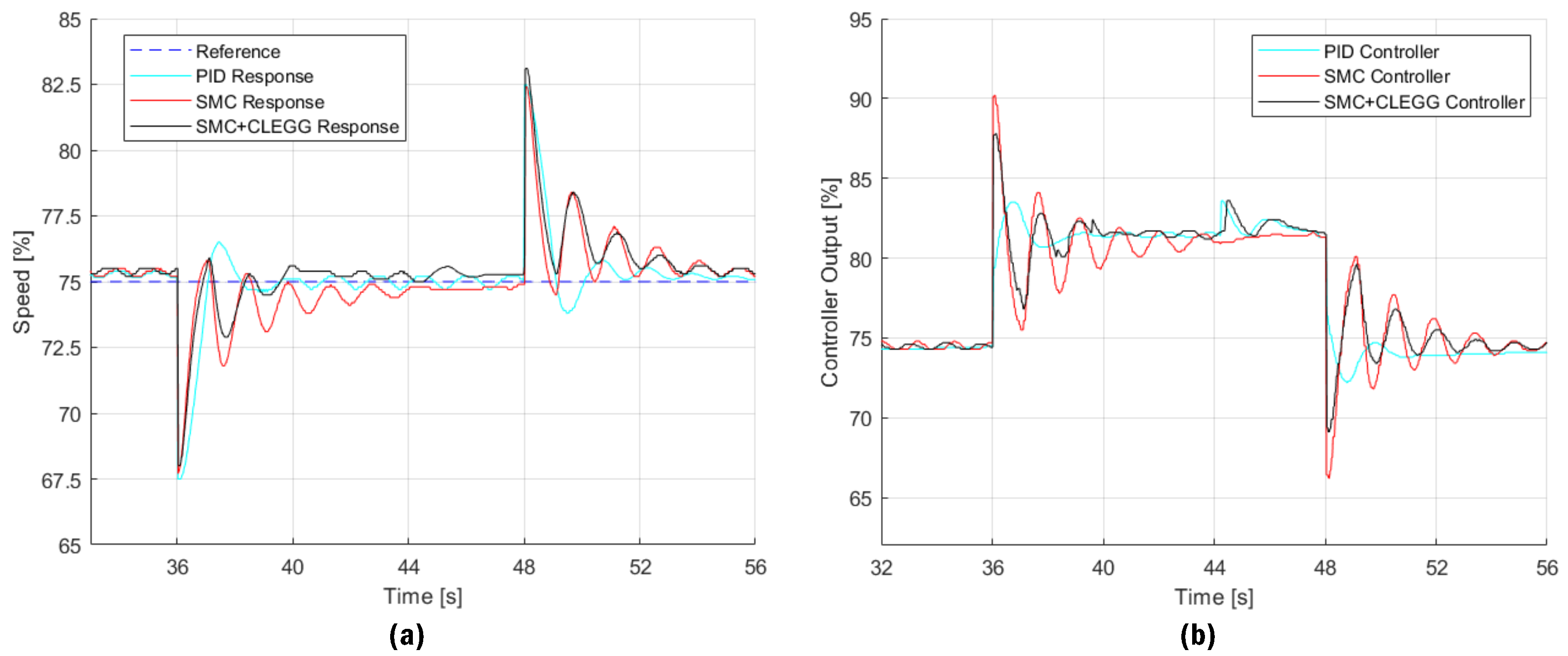
Figure 6 shows the speed response to disturbances and the corresponding output generated by the controller in reaction to these disturbances.
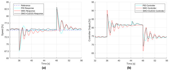
Figure 6.
Results of disturbance test. (a) Speed of the three-phase motor, (b) controller output sent to the frequency variator.
Table 2 illustrates the various performance indexes and the comparisons with the proposed control that were observed during the disturbance tests.
Table 2.
Disturbance test results.
Figure 6a shows the response of the engine speed system in the presence of a disturbance. Three controllers are compared: PID, SMC (Sliding Mode Controller), and SMC+CLEGG. The PID controller shows a fast response, but with notable oscillations before stabilizing, with a negative Mp of 10% and an improvement of 7.14%. The SMC has a slower response, but with fewer oscillations at the beginning, obtaining a negative Mp of 9.60% and an improvement of 2.86%. Finally, the SMC+CLEGG offers an intermediate performance with a negative prominence of 9.33%, showing an improvement in the establishment time (ts) compared to the SMC, with a value of 1.97 s compared to the 3.334 s of the SMC.
Figure 6b analyzes the control signal generated by each controller in response to the disturbance. The PID controller requires quick and significant adjustments, which is reflected in a TVu of 1240.80 and an IAE of 1423.04. Although these values are high, they are lower than those obtained by the SMC, which presents a TVu of 3089.00 and an IAE of 1729.10, which indicates a greater effort in correcting the disturbance. The SMC+CLEGG, although it achieves a balance by reducing both the TVu (2437.00) and the IAE (1262.49), improving the traditional SMC, the PID still offers better performance in this particular test, with lower TVu and IAE values. It should be noted that in Figure 5 and Figure 6, the speed does not stabilize at the set point but maintains a constant oscillation of approximately 0.5% in magnitude. This is due to electromagnetic noise from other elements connected in the laboratory and the vibrations of the mechanical coupling observed in Figure 2, effects that are unavoidable in the implementation of a real system.
4. Conclusions
In this work, a new sliding mode control proposal was designed and implemented on a PLC for speed control of an induction motor. Additionally, conventional PID and SMC were employed to compare the performance of the proposed control method using various performance indices.
The PID controller shows slower response times but is more stable initially, with less overshoot. The SMC provides faster response times but is characterized by higher overshoot and more chattering. The SMC+CLEGG controller effectively combines the speed of the SMC with improved stability, significantly reducing chattering due to the action of the Clegg integrator.
The SMC+CLEGG controller offers a smoother and more stable response compared to the SMC, minimizing chattering that could damage the actuators, thus prolonging their useful life. Although it has a higher TVu rating than the PID, it is still lower than the SMC. This is because sliding mode controllers allow the system to reach the set point more quickly, which requires more intense control actions. However, by reducing the windup effect of the conventional SMC, the SMC+CLEGG provides smoother control action. The SMC+CLEGG controller not only improves system accuracy and stability, but also contributes to greater energy efficiency. By minimizing oscillations and settling time, unnecessary motor work and therefore energy consumption is reduced. This is especially important in industrial applications where energy efficiency is a key factor in reducing operating costs and improving sustainability.
Author Contributions
Conceptualization, P.P.; methodology, P.P. and R.D.; software, C.C.; validation, R.D. and W.C.; formal analysis, R.D.; writing—original draft preparation, P.P.; writing—review and editing, J.Z., J.M. and W.C.; visualization, C.C.; supervision, P.P. All authors have read and agreed to the published version of the manuscript.
Funding
This research received no external funding.
Institutional Review Board Statement
Ethical review and approval were waived for this study due to the fact that no humans or animals were used.
Informed Consent Statement
Not applicable.
Data Availability Statement
Data are contained within the article.
Conflicts of Interest
The authors declare no conflicts of interest.
References
- George, T.; Ganesan, V. Optimal tuning of PID controller in time delay system: A review on various optimization techniques. Chem. Prod. Process. Model. 2022, 17, 1–28. [Google Scholar] [CrossRef]
- Alfaro, V.M.; Vilanova, R. PID control: Resilience with respect to controller implementation. Front. Control. Eng. 2022, 3, 1061830. [Google Scholar] [CrossRef]
- Chehaidia, S.E.; Kherfane, H.; Cherif, H.; Boukhezzar, B.; Kadi, L.; Chojaa, H.; Abderrezak, A. Robust nonlinear terminal integral sliding mode torque control for wind turbines considering uncertainties. IFAC-PapersOnLine 2022, 55, 228–233. [Google Scholar] [CrossRef]
- Hernandez-Barragan, J.; Rios, J.D.; Alanis, A.Y.; Lopez-Franco, C.; Gomez-Avila, J.; Arana-Daniel, N. Adaptive Single Neuron Anti-Windup PID Controller Based on the Extended Kalman Filter Algorithm. Electronics 2020, 9, 636. [Google Scholar] [CrossRef]
- Memon, F.; Shao, C. An Optimal Approach to Online Tuning Method for PID Type Iterative Learning Control. Int. J. Control Autom. Syst. 2020, 18, 1926–1935. [Google Scholar] [CrossRef]
- Lei, Z.; Zhou, Y. A kind of nonlinear PID controller for Refrigeration Systems based on Vapour Compression. IFAC-PapersOnLine 2018, 51, 716–721. [Google Scholar] [CrossRef]
- Hasan, M.W.; Abbas, N.H. Disturbance Rejection for Underwater robotic vehicle based on adaptive fuzzy with nonlinear PID controller. ISA Trans. 2022, 130, 360–376. [Google Scholar] [CrossRef] [PubMed]
- Liu, J.; Gao, Y.; Yin, Y.; Wang, J.; Luo, W.; Sun, G. Basic Theory of Sliding Mode Control. In Sliding Mode Control Methodology in the Applications of Industrial Power Systems; Springer International Publishing: Cham, Switzerland, 2020; pp. 11–25. [Google Scholar] [CrossRef]
- Gambhire, S.J.; Ravi Kishore, D.; Londhe, P.S.; Pawar, S.N. Review of sliding mode based control techniques for control system applications. Int. J. Dyn. Control 2021, 9, 363–378. [Google Scholar] [CrossRef]
- Li, S.; Yu, X.; Fridman, L.; Man, Z.; Wang, X. (Eds.) Advances in Variable Structure Systems and Sliding Mode Control—Theory and Applications; Springer International Publishing: Cham, Switzerland, 2018; Volume 115. [Google Scholar] [CrossRef]
- Prado, A.J.; Herrera, M.; Dominguez, X.; Torres, J.; Camacho, O. Integral Windup Resetting Enhancement for Sliding Mode Control of Chemical Processes with Longtime Delay. Electronics 2022, 11, 4220. [Google Scholar] [CrossRef]
- Abdedjebbar, T.; Zellouma, L.; Benchouia, M.T.; Krama, A. Adaptive linear neuron control of three-phase shunt active power filter with anti-windup PI controller optimized by particle swarm optimization. Comput. Electr. Eng. 2021, 96, 107471. [Google Scholar] [CrossRef]
- Wang, X.; Gambier, A.; Vinagre, B.M. Fractional Order PID Control with Rate-limited Anti-windup for the Pitch System of Wind Turbines. In Proceedings of the 2020 IEEE Conference on Control Technology and Applications (CCTA), Montreal, QC, Canada, 24–26 August 2020; pp. 933–938. [Google Scholar] [CrossRef]
- Díaz, R.; Camacho, O. A Comparison of Linear and Nonlinear PID Controllers Reset-Based for Nonlinear Chemical Processes with Variable Deadtime. In Applied Technologies; Botto-Tobar, M., Montes León, S., Camacho, O., Chávez, D., Torres-Carrión, P., Zambrano Vizuete, M., Eds.; Springer: Cham, Switzerland, 2021; Volume 1388, pp. 195–206. [Google Scholar] [CrossRef]
- Gude, J.J.; García Bringas, P. Proposal of a General Identification Method for Fractional-Order Processes Based on the Process Reaction Curve. Fractal Fract. 2022, 6, 526. [Google Scholar] [CrossRef]
- Borase, R.; Maghade, D.; Sondkar, S.; Pawar, S.N. A review of PID control, tuning methods and applications. Int. J. Dyn. Control 2021, 9, 818–827. [Google Scholar] [CrossRef]
- Szczepanski, R.; Kaminski, M.; Tarczewski, T. Auto-Tuning Process of State Feedback Speed Controller Applied for Two-Mass System. Energies 2020, 13, 3067. [Google Scholar] [CrossRef]
- Proaño, P.; Capito, L.; Rosales, A.; Camacho, O. A dynamical sliding mode control approach for long deadtime systems. In Proceedings of the 2017 4th International Conference on Control, Decision and Information Technologies (CoDIT), Barcelona, Spain, 5–7 April 2017; pp. 108–113. [Google Scholar] [CrossRef]
- Camacho, O.; Smith, C.A. Sliding mode control: An approach to regulate nonlinear chemical processes. ISA Trans. 2000, 39, 205–218. [Google Scholar] [CrossRef] [PubMed]
- Teel, A.R. Continuous-Time Implementation of Reset Control Systems. In Trends in Nonlinear and Adaptive Control: A Tribute to Laurent Praly for his 65th Birthday; Jiang, Z.P., Prieur, C., Astolfi, A., Eds.; Springer International Publishing: Cham, Switzerland, 2022; pp. 27–41. [Google Scholar] [CrossRef]
- Moreno, J.C.; González, J.; Navarro, A.; Guzmán, J.L. New Tuning Rules of PI+CI Controllers for First-Order Systems. Actuators 2024, 13, 67. [Google Scholar] [CrossRef]
Disclaimer/Publisher’s Note: The statements, opinions and data contained in all publications are solely those of the individual author(s) and contributor(s) and not of MDPI and/or the editor(s). MDPI and/or the editor(s) disclaim responsibility for any injury to people or property resulting from any ideas, methods, instructions or products referred to in the content. |
© 2024 by the authors. Licensee MDPI, Basel, Switzerland. This article is an open access article distributed under the terms and conditions of the Creative Commons Attribution (CC BY) license (https://creativecommons.org/licenses/by/4.0/).