Abstract
MEMS capacitive pressure sensors have proven to be more reliable in terms of temperature drift and long-term stability when compared to MEMS piezoresistive pressure sensors. In this study, a MEMS capacitive pressure sensor using micromachined technology has been designed and fabricated. As the movable electrode, a silicon membrane is used, while the fixed electrode is a gold metal film on a glass substrate. There is no deformation of the silicon membrane when the pressure is equal on both sides. As a result of the pressure of 0 kPa applied to the silicon membrane, a capacitance exists between it and the metal electrode. Differences in pressure on both sides of the silicon membrane will cause the membrane to deform. Silicon membranes deform due to pressure differences, which affect the capacitance between metal electrodes and silicon membranes. MEMS capacitive pressure sensors benefit from the superior mechanical properties of silicon material compared to metal-based sensors. Capacitive MEMS sensors are more desirable for applications requiring high performance and stability as compared to metal pressure sensors. This device is suited to measuring blood pressure with a measurement range of 0–45 kPa. When applied pressure was 0 kPa, the measurement capacitance was 3.61 pF, and when 45 kPa was applied, it was 7.19 pF.
1. Introduction
There are two electrodes in a MEMS capacitive pressure sensor, one of which is movable and one of which is fixed. A silicon membrane is used to make a movable electrode, and a metal film is used to make a fixed electrode. To create silicon membrane structures, silicon micromachining processes are used. As pressure is applied to a silicon membrane structure, the structure is deformed to determine the outside pressure. In terms of mechanical properties, silicone materials are excellent, as they have high yield strength, no plastic delay, and mechanical hysteresis characteristics. As a result of silicon’s superior mechanical properties, MEMS capacitive pressure sensors perform far better than metal sensors. MEMS capacitive pressure sensors are better suited to high-performance and high-stability applications than metal pressure sensors.
MEMS capacitive pressure sensors have a higher level of performance when compared with MEMS piezoresistive pressure sensors, particularly in terms of temperature drift, long-term stability, and others. MEMS piezoelectric capacitive sensors for underwater applications have been reported [1,2]. MEMS capacitive pressure sensors are developed and produced by many companies and research centers. A MEMS capacitive pressure sensor serves as the core-sensitive component of the sensors used by the VTI barometric pressure sensor and altimeter, as well as the Fuji gauge pressure sensor [3,4]. A high-sensitivity MEMS pressure sensor chip for different ranges (1 to 60 kPa) utilizing the novel electrical circuit of a piezo-sensitive differential amplifier with a negative feedback loop (PDA-NFL) is developed. This sensor has a sensitivity of 44.9 mV/kPa/V and a nonlinearity error of 0.26 (for 0.5 kPa). It has a zero-pressure output signal (offset) of 14 mV [5]. The experimental results of the pressure sensor showed that a sensitivity of 4.72 mV/kPa/V and a non-linearity error of 0.18% FSO at 20 °C were achieved in the pressure range of 0–3 kPa. It has a zero-point offset voltage of 5.78 mV [6]. In accordance with the FEM results, the experimental results showed that the fabricated pressure sensors using bossed diaphragms combined with side edge and diagonal directional positioned peninsula islands had sensitivities of 0.065 mV/V/Pa and 0.060 mV/V/Pa, respectively, and nonlinearity errors of 0.33% FS and 0.30% FS, respectively, within the pressure range of 0–500 Pa [7].
In this paper, a silicon-glass capacitive pressure sensor is described. MEMS micromachining was used to fabricate the silicon membrane, and silicon-glass anodic bonding enabled sensitive devices to be achieved. Silicon membranes are used as movable electrodes, while gold metal films on glass substrates are used as fixed electrodes.
2. Fabrication Process
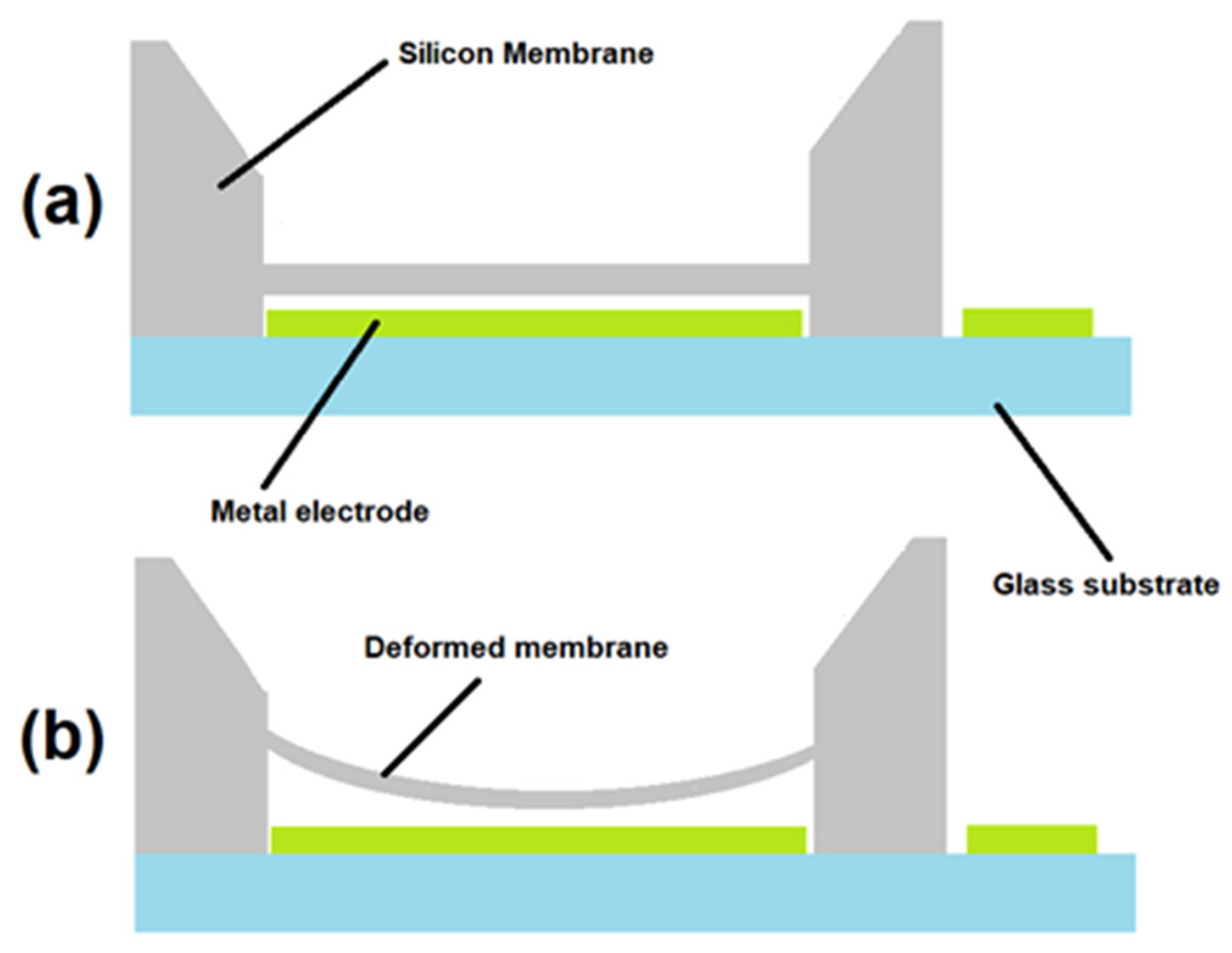
In Figure 1, MEMS capacitive pressure sensors are shown in their structure and working principle. Several materials are used in the design of MEMS capacitive pressure sensors, including silicon membranes as movable electrodes, gold metal films as fixed electrodes, and glass substrates as support. The fixed electrode needs to maintain a consistent electrical connection for accurate capacitance measurements. Therefore, gold is an excellent electricity conductor, essential for creating a reliable capacitive sensing element. Gold exhibits low contact resistance, forming good electrical connections with other materials and surfaces. This is crucial for minimizing signal loss and maintaining accurate measurements. In our current work, MEMS (Micro-Electro-Mechanical Systems) capacitive pressure sensors with absolute pressure are used as sensing mechanisms. The sensors measure the pressure by detecting the change in capacitance between two conductive plates or electrodes because of the applied pressure. When pressure is applied, the distance between the plates changes, causing a variation in the capacitance, which can then be converted into an electrical signal proportional to the applied pressure. There is a pressure difference between the two sides of the silicon membrane, and the capacitance between the silicon membrane and the metal electrode is the result of this pressure difference between the two sides [8,9].
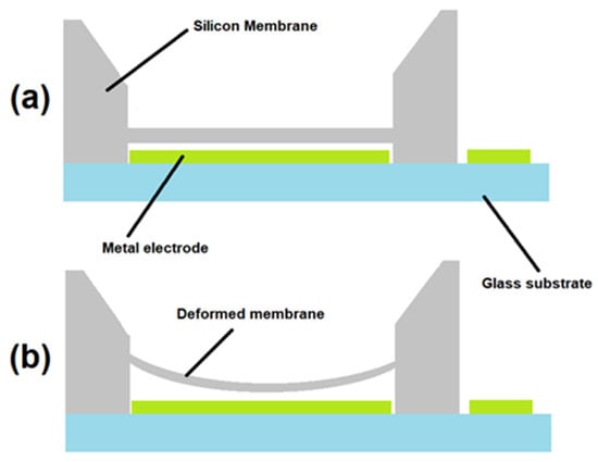
Figure 1.
Mechanism of MEMS capacitive pressure sensors. (a) When there is no pressure. (b) Deformation of the silicon membrane in response to pressure.
Figure 2 shows the fabrication process of the MEMS capacitive pressure sensor. The process consists of two parts. The silicon substrate process is one part of the process. To fabricate the silicon membrane, silicon etching techniques were used. Another part is the glass substrate process. To achieve a fixed metal electrode, metallization and patterning techniques were used. The silicon and glass wafers were bonded using silicon-glass anodic bonding technology. Anodic bonding has been the most widely used bonding method for MEMS because it is easy, reliable, and highly yielding. In principle, anodic bonding can be performed between electron-conductive materials and ion-conductive materials. The most typical combination is Si and borosilicate glass, which shows ion conductivity at 300 °C or higher. Other semiconductors and metals except Ag can also be anodically bonded with glass, but different kinds of glass for Si must be used to match the coefficient of thermal expansion. The merit, which is not found in other bonding methods, is that an electrostatic attractive force of about 20 kgf/cm2 works between wafers, and thus bonding uniformity, i.e., yield, is excellent without special cares such as uniform loading. In addition, the reliability of bonding strength and hermeticity have been proven in a long history of MEMS applications [10]. Typical bond strength is between 10 and 20 MPa according to pull tests, which is higher than the fracture strength of glass [11]. Chips were separated, and sensor dies were created through dicing. The developed MEMS capacitive pressure sensor chip is shown in Figure 2.
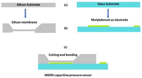
Figure 2.
Process for fabricating MEMS capacitive pressure sensors. (a) Sillicon and Glas subtrate. (b) Silicon membrane and deposition of molybdeum as an electrode on glass subtrate. (c) Cutting and bonding of MEMS pressure sensor.
3. Results and Discussion
Gas pressure was applied using a GE Sensing PACE5000 precision pressure controller. This pressure measurement range is suitable to measure blood pressure from 0 to 45 kPa. A pressure of 0 kPa resulted in a measurement capacitance of 3.61 pF, while a pressure of 45 kPa resulted in a measurement capacitance of 7.19 pF. Figure 3 shows the results of the capacitance-pressure curve and elastance-pressure curve measurements. As expected, with the increase in pressure, the capacitance of the silicon membrane increases while the elastance decreases.
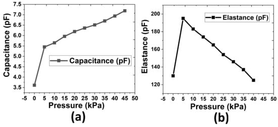
Figure 3.
Measurement curves for capacitive pressure sensors using MEMS technology. (a) Graph of capacitance vs. pressure. (b) Graph of elastance vs. pressure.
4. Conclusions
This work represents the design and fabrication of a MEMS capacitive pressure sensor. Anodic bonding of silicon glass was used to fabricate the sensor using micromachined technology. A silicon membrane is used as a movable electrode, and a gold metal film on a glass substrate is used as a fixed electrode. With an applied pressure of 0 kPa, the measurement capacitance is 3.61 pF, and with a full operating range of 45 kPa, it is 7.19 pF. Capacitance increases with the increase in pressure, while elastance decreases. This type of measurement is suitable for the application of blood pressure measurements because the operating pressure ranges from 0 kPa to 45 kPa.
Funding
This research received no external funding.
Institutional Review Board Statement
Not applicable.
Informed Consent Statement
Not applicable.
Data Availability Statement
The data presented in this study are available within the article, and they are presented in every graph. There is no more data apart from the presented.
Conflicts of Interest
The author declares no conflict of interest.
References
- Abdul, B.; Mastronardi, V.M.; Qualtieri, A.; Guido, F.; Algieri, L.; Rizzi, F.; De Vittorio, M. Design, Fabrication and Characterization of Piezoelectric Cantilever MEMS for Underwater Application. Micro Nano Eng. 2020, 7, 100050. [Google Scholar] [CrossRef]
- Abdul, B.; Mastronardi, V.M.; Qualtieri, A.; Algieri, L.; Guido, F.; Rizzi, F.; De Vittorio, M. Sensitivity and Directivity Analysis of Piezoelectric Ultrasonic Cantilever-Based Mems Hydrophone for Underwater Applications. J. Mar. Sci. Eng. 2020, 8, 784. [Google Scholar] [CrossRef]
- Available online: http://www.vti.se/ (accessed on 8 May 2023).
- Available online: https://www.fujielectric.com/ (accessed on 8 May 2023).
- Basov, M. Pressure Sensor with Novel Electrical Circuit Utilizing Bipolar Junction Transistor. In Proceedings of the 2021 IEEE Sensors, Sydney, Australia, 31 October–3 November 2021; pp. 1–4. [Google Scholar] [CrossRef]
- Guan, T.; Yang, F.; Wang, W.; Huang, X.; Jiang, B.; Zhang, D. The Design and Analysis of Piezoresistive Shuriken-Structured Diaphragm Micro-Pressure Sensors. J. Microelectromech. Syst. 2017, 26, 206–214. [Google Scholar] [CrossRef]
- Xu, T.; Lu, D.; Zhao, L.; Jiang, Z.; Wang, H.; Guo, X.; Li, Z.; Zhou, X.; Zhao, Y. Application and Optimization of Stiffness Abruption Structures for Pressure Sensors with High Sensitivity and Anti-Overload Ability. Sensors 2017, 17, 1965. [Google Scholar] [CrossRef] [PubMed]
- Wang, S.; Feng, Y. Micro capacitive vacuum sensor based on MEMS. In Proceedings of the 2010 IEEE 5th International Conference on Nano/Micro Engineered and Molecular Systems, Xiamen, China, 20–23 January 2010; pp. 1160–1164. [Google Scholar] [CrossRef]
- He, F.; Huang, Q.-A.; Qin, M. A silicon directly bonded capacitive absolute pressure sensor. Sens. Actuators A Phys. 2007, 135, 507–514. [Google Scholar] [CrossRef]
- Tanaka, S. Wafer-level hermetic MEMS packaging by anodic bonding and its reliability issues. Microelectron. Reliab. 2014, 54, 875–881. [Google Scholar] [CrossRef]
- Esashi, M. Encapsulated micromechanical sensors. Microsyst. Technol. 1994, 1, 2–9. [Google Scholar] [CrossRef]


Disclaimer/Publisher’s Note: The statements, opinions and data contained in all publications are solely those of the individual author(s) and contributor(s) and not of MDPI and/or the editor(s). MDPI and/or the editor(s) disclaim responsibility for any injury to people or property resulting from any ideas, methods, instructions or products referred to in the content. |
© 2023 by the author. Licensee MDPI, Basel, Switzerland. This article is an open access article distributed under the terms and conditions of the Creative Commons Attribution (CC BY) license (https://creativecommons.org/licenses/by/4.0/).