Proceeding Paper

Sealing Technologies for the Manufacturing of Bipolar Plates via Active and Passive Hydroforming †

Fraunhofer Institute for Machine Tools and Forming Technology, 09126 Chemnitz, Germany
*
Author to whom correspondence should be addressed.
Presented at the 28th Saxon Conference on Forming Technology SFU and the 7th International Conference on Accuracy in Forming Technology ICAFT, Chemnitz, Germany, 2–3 November 2022.
Eng. Proc. 2022, 26(1), 11; https://doi.org/10.3390/engproc2022026011
Published: 9 November 2022

Abstract

:
Hydrogen technology is central to the process of turning away from fossil fuels. Electrolyzers and fuel cells of various sizes are needed to implement the hydrogen strategy. The cost-efficient forming of bipolar plates is key to the implementation of this strategy. Based on previous research, this paper presents active and passive hydroforming using the example of the production of bipolar plates for fuel cells. Furthermore, different systems for sealing the hydroforming pressure between tool and sheet are presented and compared with regard to their behavior in forming tests, their failure characteristics and the resulting process parameters.

1. Introduction

1.1. Motivation

The use of hydrogen as a storage medium for strongly fluctuating renewable-energy sources has been widely discussed, especially since the publication of the national hydrogen strategy of the German government in mid-2020 [1]. Electrolyzers and fuel cells of different sizes are needed to implement the hydrogen strategy. Table 1 shows the expected hydrogen demand and electrolysis capacity in Germany and the EU.
To achieve the necessary hydrogen-production capacity, a large number of electrolyzers and, thus, bipolar plates are required, which at best have to be produced in large quantities within a very short time. Bipolar plates have optimized flow fields to ensure the transport of water and the separation of product gases. The materials used are coated stainless steels or titanium alloys. The typical processes for high-volume production are forming processes, such as hollow stamping, hollow embossing and hydroforming. In this paper, hydroforming is addressed.

1.2. State of the Art

In the following, the research on the classic active hydroforming process, the passive hydroforming process and the sealing systems to be used between the filling plate and the component is presented.

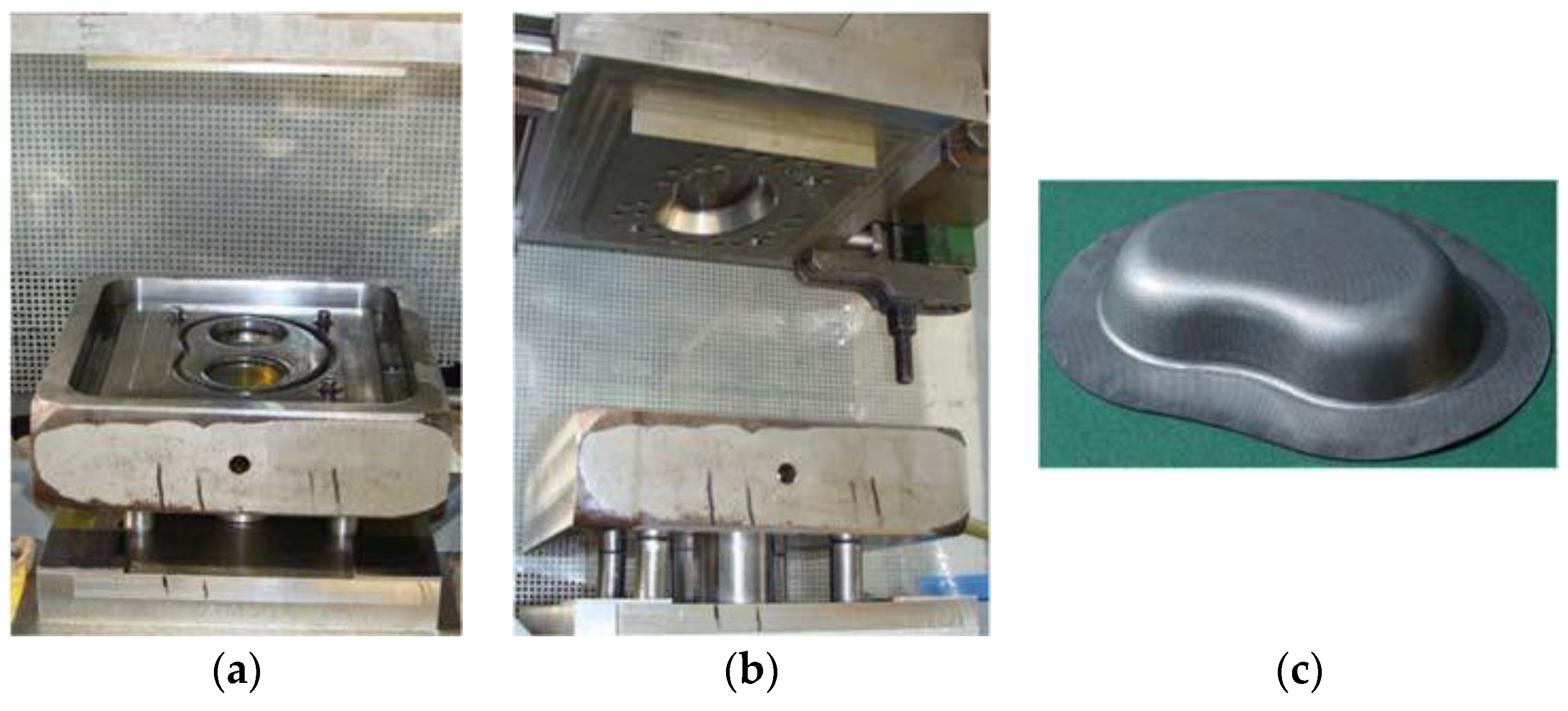
1.2.1. Active Hydroforming

The process principle of classic active hydroforming is shown in Figure 1.
The part geometry is mapped on only one side of the mold. The high pressure required for forming is generated by external pressure intensifiers and injected into the filling/water plate via high-pressure hoses. In hydroforming, the medium pressure acts against the press-closing force, which is the reason why the high closing force of the hydroforming press is required. An appropriately dimensioned sealing system is necessary around the forming zone. In the case of production from coil, seven to eight strokes per minute can currently be achieved [4], but if appropriate tool concepts for parallel production are applied, up to approximately 30 parts per minute can be produced within one press [5,6].

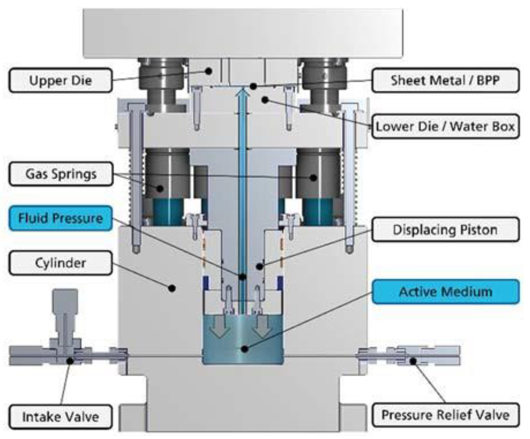
1.2.2. Passive Hydroforming

The aim of passive hydroforming is to avoid the need for water hydraulics on the press side, including pressure intensifiers. This allows the use of hydroforming on presses without this high-pressure technology. The process was used for the first time at Fraunhofer IWU for manufacturing a kidney dish with a maximum forming pressure of 37 MPa (see Figure 2 [7]). Until now, passive hydroforming has not been used in processes with forming pressures of up to 200 MPa, as they are required for producing bipolar plates.
The process of active and passive hydroforming differs particularly in the phase of the buildup of the clamping force and forming pressure. In classic active hydroforming, first the closing force is built up after the press is closed and then the forming pressure is produced by means of pressure intensifiers. In passive hydroforming, the buildup of high pressure depends on the path of the press stroke and the buildup of clamping force. Depending on the press used, the buildup of high pressure can therefore be very fast and shorter cycle times can be achieved. Table 2 shows a comparison of the cycle times to be expected when working from the coil.

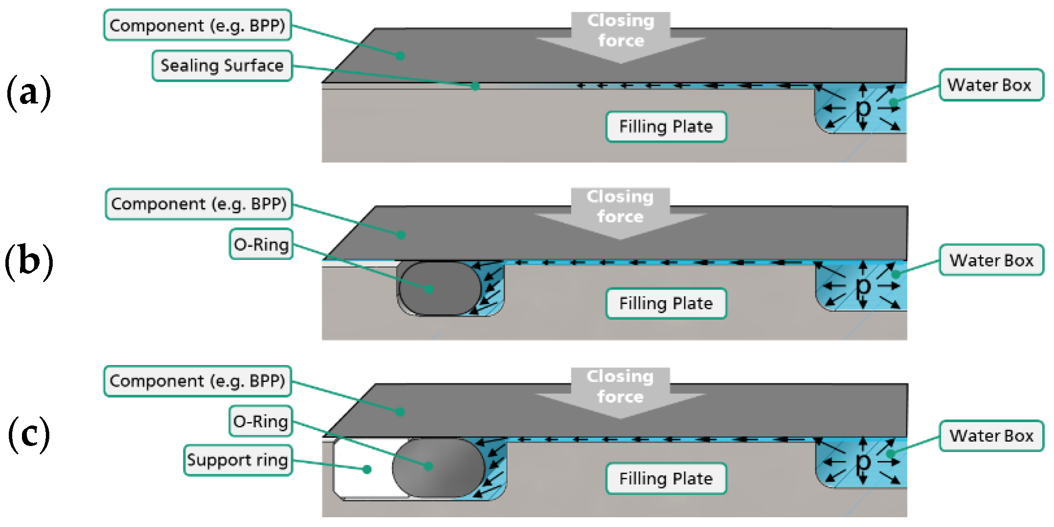
1.2.3. Sealing Systems for the Hydroforming of Sheet Metal Components

Tools for sheet hydroforming are comparatively simple. The sealing between the sheet to be formed and the filling plate is the most challenging aspect of mold technology. To compare the properties of different sealing materials and concepts, numerous investigations considering single-sheet hydroforming focused on this topic [8,9]. In addition to elastomer seals (O-ring [10,11], Kant-Seal and quad-ring), elastomer-Teflon and elastomer-metal seals have been investigated [12,13]. O-rings were also investigated with an additional metallic back-up ring [14,15]. Furthermore, experimental tools without additional sealing element [16], with metallic pinch-off and sealing bead [11], viscous [17] or magnetic rheological fluids [18] or fluids with integrated fiber materials [19,20,21] for sealing smaller leakages/gaps are presented in the literature. For tools without an additional sealing element and a purely force-fit sealing in the flange area, very high press forces are required. From investigations with axially symmetrical workpieces, a ratio of the surface pressure in the flange area to the internal pressure of 1.6 was recommended [12,13]. Due to the comparatively high forming pressures of approximately 200 MPa required for bipolar plate production, very high surface pressures and closing forces result from such technically simple systems. In molds for hydroforming sheets with wall thicknesses of more than 0.5 mm, Fraunhofer IWU has so far mainly used copper sealings [22]. In addition to the sealing function, they must also allow the relative movement of the sheet on the sealing so that material can flow into the forming zone.
In the hydroforming of thin metal foils, as used for bipolar plates for fuel cells and electrolyzers, it is not necessary for material to flow into the forming zones, but as the sealing must not leave any marks on the components, it can be placed as far as possible into the partly flat boundary area of the component contour. Therefore, new sealing concepts were developed for hydroforming of components from thin metal foils. A compromise needed to be found between technological feasibility, costs and the necessary clamping force. The latter depends on the operating principle of the sealing (purely metallic sealing, use and contour of flexible sealing elements) and must be kept as low as possible due to the limited closing forces on hydroforming presses and the comparatively large effective areas of the components.

1.3. Aims and Approach

In principle, the hydroforming of bipolar plates is the currently applied method, but the process still offers potential for further improvement. The main objectives are to reduce the cycle time and the necessary press-clamping force. As explained above, passive hydroforming has high potential to reduce cycle times. Therefore, the aim of this study was to adapt and test this process variant for high forming pressures as they are required for manufacturing bipolar plates. The press-closing forces during hydroforming depend on the forming pressure, the pressure-loaded area and the required safety. The forming pressure and pressure-loaded area are basically determined by the part geometry, so that only the safety factor is available for the possible optimization of the closing forces. One possible factor influencing safety is the sealing system between the sheet to be formed and the mold. Thus, the improvement of this sealing system is a central aspect of the presented work. Various systems were developed and compared in trials.

2. Materials and Methods

2.1. Development of the Passive Hydroforming for Bipolar Plate

The die concept for passive hydroforming was further developed, as shown in Figure 3. It is important that during the press stroke, a sufficient clamping force acts on the die face to be sealed between the water box and the die engraving so that the system remains closed and cannot open. In the design of the cylinder integrated in the mold for pressure buildup, care must therefore be taken to ensure a suitable ratio of the effective area of the piston to the forming area. In addition, a basic clamping force must act on the system to be sealed in order to prevent the early opening of the system between the die and the water box. This is possible with the aid of suitably designed springs or gas-pressure dampers acting on the fluid distributor. When the press is closed, the movement of the displacing piston compresses the active medium enclosed in the die. This allows sufficient pressure to be generated for forming bipolar plates.
Table 3 summarizes the parameters for initial tests of passive hydroforming and the reference parameters used for a comparison with active hydroforming. Due to the restrictions regarding the availability of tools and machines, the tests for active and passive hydroforming were carried out on different production presses with different tools.

2.2. Development of Sealing Systems

In addition to the basic technological usability of the systems, the aim of the sealing-system developments and, thus, of the tests was, above all, to identify a system with which a reliable seal between the part to be formed and the mold can be ensured with the lowest possible clamping force. This is the basis for reliable production of good parts of maximum size at sufficient forming pressure on the smallest possible presses.
A purely metallic sealing, without additional elements or sealing beads, is the simplest version of a high-pressure seal and works only via the force fit of surfaces pressed against each other. Here, the mold engraving and filling plate are pressed against each other as a result of the press-closing force. The outer-edge impact surface corresponds to the sealing surface. Figure 4a shows schematically the application of this principle on the basis of a forming operation of bipolar plates. The key factors for the sealing effect are the effective press-closing force and the respective surface roughnesses of the component and the sealing surface of the filling plate. Limiting factors are the surface pressure, which can be exerted by the filling plate on the sealing surface and the available press closing force. This sealing concept is particularly suitable for forming at high temperatures. This can be helpful, for example, in the manufacturing of bipolar plates made of titanium.
An O-ring (Ø3 mm, NBR70 acc. to ISO 3601) arranged in a groove (Figure 4b and Figure 5a) is the simplest type of sealing with a flexible sealing element and allows the lowest circumferential material addition on the sheet for the sealing, of 10 mm. It thus enables comparatively good material-utilization rates [23]. For example, for a bipolar plate measuring 200 by 300 mm, this is approximately 85 percent. Due to the high pressures to be sealed, the O-ring groove is modified compared to the standard O-ring groove. It is slightly smaller compared to the variants with a support ring, which reduces the area acted upon by the forming pressure. However, since the groove is sharp-edged on the upper side, there is a risk of the O-ring flowing into the smallest gaps between the filler plate and the sheet during the process and, thus, becoming damaged.
To prevent this damage, a variant of the O-ring seal was designed with an additional one-piece milled support ring, which is shown in Figure 4c and Figure 5b. The support ring has a round contour in the area where it contacts the O-ring and is slightly higher than the sealing ring groove. This is to prevent the risk of the O-ring flowing into the gap between filling plate and sheet. In addition to soft metals, plastics are most suitable semifinished products for the support ring. Since tests with other components have already shown that support rings made of copper are very sharp-edged in the event of defects in and subsequent damage to O-rings, Polyetheretherketon (PEEK) was initially used for the tests. Since the manufacturing of one-piece milled support rings for the forming of large components is associated with very poor material utilization of the high-performance plastic and, thus, very high manufacturing costs, a search was carried out for a more economical variant. One suitable method is 3D printing, which was used to manufacture a one-piece 3D-printed support ring (Figure 5c) from filament of the material ePLA-ST [24]. On the other hand, a multi-part milled support ring (Figure 5d) made of PEEK was fabricated to improve the material-utilization rate during milling.
Tests with the same test parameters were carried out for all sealing systems to investigate their effect and, in particular, their influence on the closing force. The target pressure was 250 MPa. The closing force was varied in three stages (2500 kN, 2000 kN and 1500 kN) and each test was performed three times. The selected process parameters gave safeties for the theoretical closing force between 0.9 and 1.5. On all tests, it was evaluated whether leakage occurred and at which pressure and closing force. The pressurized areas could then be used to determine the necessary safety of the closing force. Of particular interest were the process parameters at which leakage started. The Dunkes HS3-1500 press of the Fraunhofer IWU (Chemnitz, Germany) used here does not operate with constant force control, but rather blocks the hydraulic oil in the ram via a valve after the clamping force is applied. If the forming pressures are too high, the mold opens. This increases the pressure in the ram cylinder and, thus, the clamping force. In areas where the mold seal can still compensate for this, the mold initially remains closed. The closing force can then be used to evaluate the forming tests.

3. Results

3.1. Comparison of Active and Passive Hydroforming

Exemplary formed bipolar plates are shown in Figure 6a for the process variant of active hydroforming and in Figure 6b for the process variant of passive hydroforming. In the case of active hydroforming, the target-forming pressure of 200 MPa was applied and even fine details and sharp edges were formed very accurately.
So far, only initial trials have been carried out with the mold for passive hydroforming. Forming pressures of over 300 MPa were achieved. The figure shows a component which was very accurately formed at 200 MPa. This demonstrated the potential of the process. Further basic tests with the mold are planned for the near future in order to understand the relationships between the ram stroke and the internal pressure and, in particular, to be able to develop the fundamentals for process control.

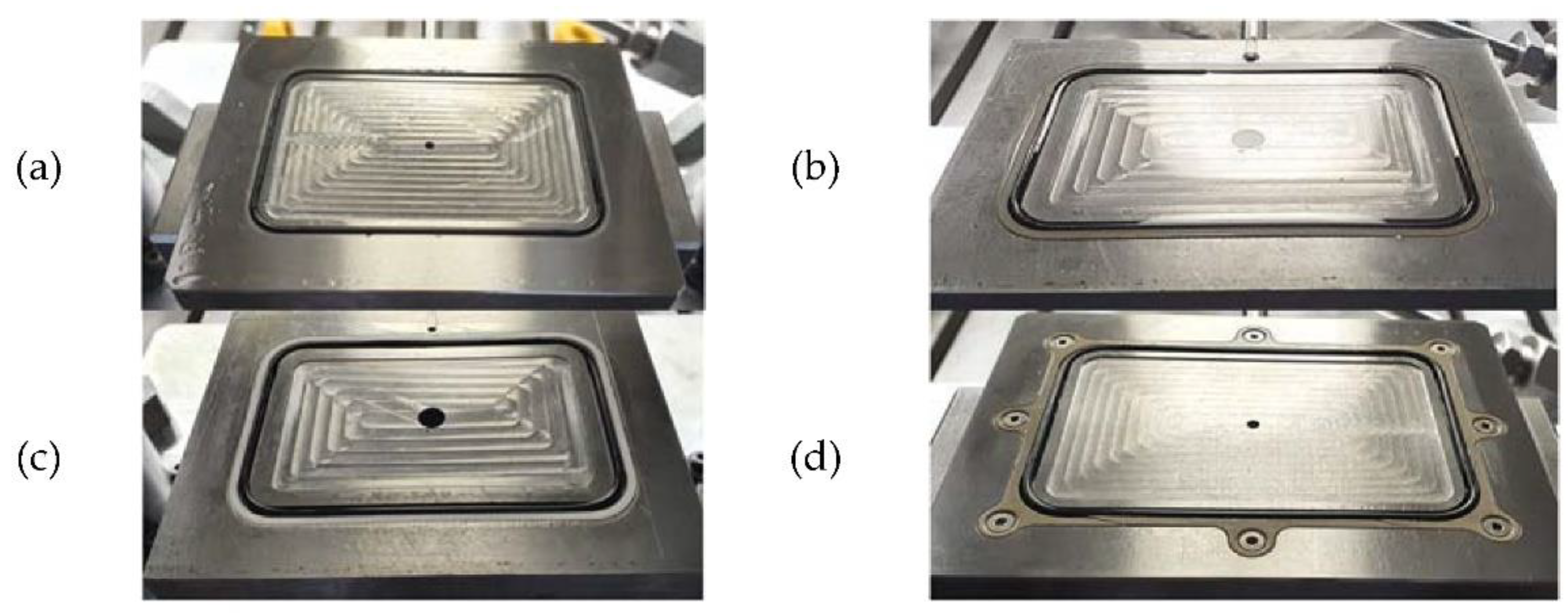
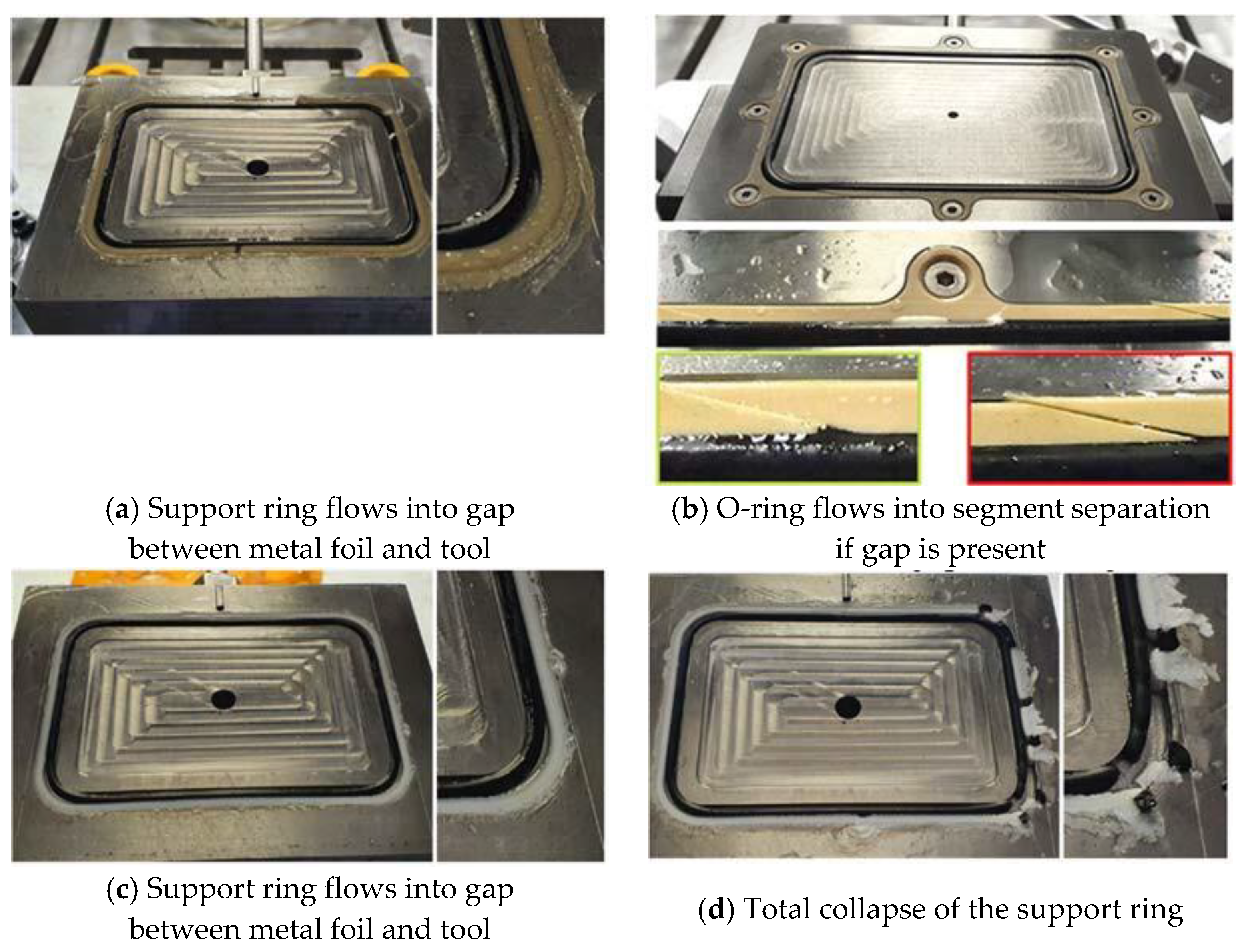
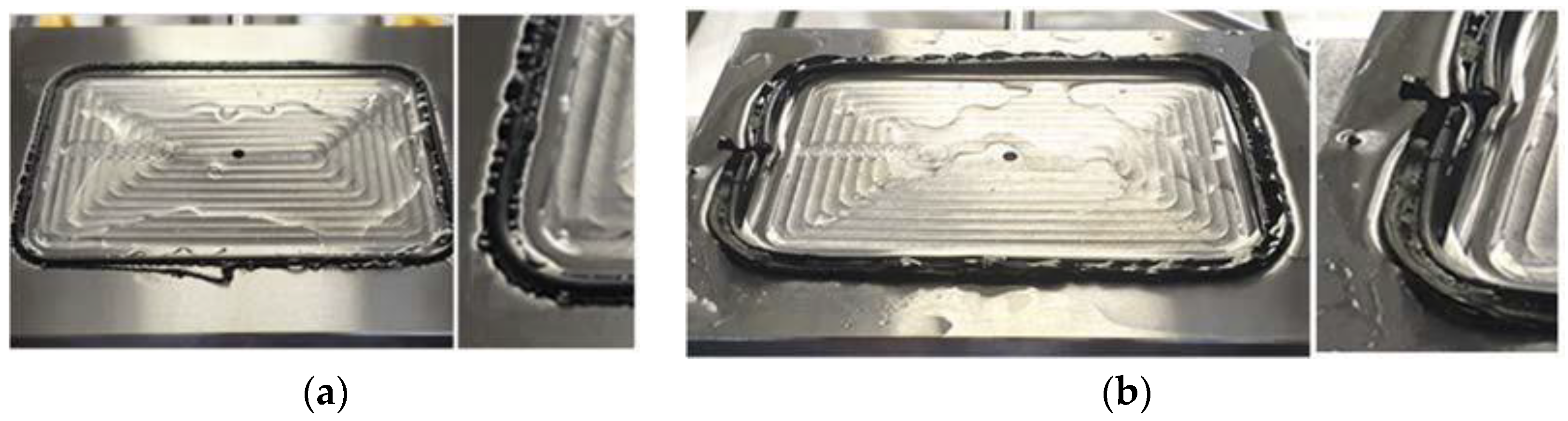
3.2. Sealing Systems for the Hydroforming of Sheet-Metal Components

The sealing systems were tested regarding their usability; typical failure cases were identified and possible optimization approaches were deduced. As expected, forming with a purely metallic sealing, without additional elements or sealing beads required very high closing forces. At a closing force in the range of 2.5 times the theoretical closing force (pressurized area multiplied by the maximum forming pressure), leakage already occurred at the mold.
By using a simple O-ring sealing, the necessary closing force was significantly reduced. Thus, the first leakages occurred there when the closing force fell below a safety level of 30 percent, i.e., 1.3 times the theoretical closing force. However, at high forming pressures, the O-rings were pressed into the smallest gaps between the sheet metal and the mold. In connection with the sharp-edged O-ring groove, this led to damage to the O-ring (Figure 7) Therefore, this sealing is not recommended for series production.
The various variants with sealing by a combination of support ring and O-ring showed comparable behavior with regard to the necessary clamping force. Leakage occurred when the clamping force falls below the safety level of 35 to 40 percent. However, the failure behavior was quite different (Figure 8).
The one-piece milled support rings failed because the mold opened due to the insufficient clamping force and the support ring flows into the gap between the mold and the workpiece. With the multi-part milled support rings, the O-ring first flowed into any gaps between the support-ring segments and therefore failed before the support ring. This could have been avoided if the division plane of the support rings had been arranged at an angle of, for example, 15° from the horizontal parting plane of the mold, so that any gaps were compressed by the press-closing force. The 3D-printed support ring was printed using the filament process and had hollow spaces between the deposited filament webs. These filled with water at high pressure and the ring broke when the mold was opened. Support-ring O-ring systems require slightly higher closing force than a pure O-ring sealing. However, sealing systems are much more durable. At Fraunhofer IWU, a combination of O-ring and one-piece PEEK support ring was used for about 1000 press strokes without failure or clearly visible wear.

4. Conclusions

It was shown that both active hydroforming and passive hydroforming can be used for manufacturing bipolar plates. Passive hydroforming offers the possibility of using presses which were not originally built for hydroforming and do not have a water hydraulic system. This means that even drawing and forging presses can be used for the hydroforming of bipolar plates. Further investigations are necessary to compare the achievable cycle times of the two processes in detail. However, it can be assumed that the cycle time for passive hydroforming is up to 50 percent lower than that of active hydroforming. To optimize the cycle time, the fully automated production of the coil and the trimming of the part must also be taken into account.
The comparison of the sealing systems showed that forming without additional sealing elements is only possible with very high closing forces for comparatively small parts. Pure O-ring seals offer the highest potential for reducing the press-closing force, but are subject to very high wear. As a compromise, combined O-ring support-ring systems are suitable for the serial production of hydroformed components. With these systems, the necessary safety for the closing force is approximately 40 percent. Based on a forming pressure of approximately 200 MPa, a pressurized area of a maximum of 0.18 m2 was achieved on a 50,000-kilonewton press commonly used in industry. This enables the production of larger bipolar plates for electrolyzers with one part per press stroke, as well as the multiple production of smaller bipolar plates for fuel cells for mobile applications.
Laboratory tests suggest that the cost-effective production of the support rings by means of 3D printing or as a multi-part milled design is also possible but here, further development work is necessary with regard to durability and manufacturing quality. With regard to a fully automated production process, hydroforming must also be adapted to work from coil and additional trimming stages and stacking systems must be integrated, as the parts must be handled very carefully to prevent damage.

Author Contributions

Conceptualization, A.A. (André Albert); methodology, A.A. (André Albert); investigation, A.A. (Andreas Anders); writing—original draft preparation, A.A. (André Albert) and A.A. (Andreas Anders); writing—review and editing, V.P., V.K. and M.D.; visualization, A.A. (Andreas Anders). All authors have read and agreed to the published version of the manuscript.

Funding

This research is supported by the Federal Ministry for Economic Affairs and Climate Action (BMWK) on the basis of a decision by the German Bundestag (funding reference number KK5048721MP1) and by the Sächsische Aufbaubank (funding reference number 100551846/4109).

Institutional Review Board Statement

Not applicable.

Informed Consent Statement

Not applicable.

Data Availability Statement

Not applicable.

Conflicts of Interest

The authors declare no conflict of interest. The funders had no role in the design of the study; in the collection, analyses, or interpretation of data; in the writing of the manuscript, or in the decision to publish the results.

References

  1. Uchtmann, H. Schuler Pressen GmbH: “Großserienfertigung von metallischen Bipolarplatten für Brennstoffzellen” in 40. In Kolloquium Blechverarbeitung; EFB: Hannover, Germany, 2022; ISBN 978-3-86776-586-2. [Google Scholar]
  2. Fraunhofer ISE-Eine Wasserstoff-Roadmap für Deutschland. 2020, p. 10. Available online: https://de.statista.com/statistik/daten/studie/1195138/umfrage/prognosen-zur-nachfrage-nach-wasserstoff-in-deutschlandund-in-der-eu/ (accessed on 6 January 2022).
  3. Siegert, K.; Lösch, B. Hydroblechumformung. In Hydroforming von Rohren, Strangpressprofilen und Blechen, Band 1; Siegert, K., Ed.; Springer: Berlin/Heidelberg, Germany, 1999; p. 263. ISBN 3-88355-284-4. [Google Scholar]
  4. Porstmann, S.; Wannemacher, T.; Drossel, W.-G. A comprehensive comparison of state-of-the-art manufacturing methods for fuel cell bipolar plates including anticipated future industry trends. J. Manuf. Process. 2020, 60, 366–383. [Google Scholar] [CrossRef]
  5. Gräbener Maschinentechnik GmbH & Co. KG. Von der Individuellen Einzelanlage bis hin zur Skalierbaren Fertigungslinie. Available online: https://www.graebener.com/de/fertigungsanlagen (accessed on 17 October 2021).
  6. Kapp, D. Hydroformwerkzeug. European Patent EP2221125B1, 28 September 2011. [Google Scholar]
  7. Budai, A.F.; Achimas, G.; Neugebauer, R.; Pröhl, M. Method and Tool Design for Passive Sheet Metal Hydroforming on Conventional Single Action Presses. J. Manuf. Sci. Eng. 2013, 135, 021014. [Google Scholar] [CrossRef]
  8. von Finkenstein, E.; Gartzke, A.; Homberg, W.; Kleiner, M.; Kollek, R.; Szücs, E.; Weidner, T. Entwicklung von Verfahren und Werkzeugsystemen zur Hydroumformung höherfester Stahlbleche; Forschungsvereinigung StahlAnwendung e.V.: Düsseldorf, Germany, 1999; ISBN 3-930621-99-1. [Google Scholar]
  9. Krei, M. Stand der Dichtungstechnik für IHU-Werkzeuge. In Hydroforming von Rohren, Strangpressprofilen und Blechen, Band 1; Siegert, K., Ed.; Springer: Berlin/Heidelberg, Germany, 1999; p. 461. ISBN 3-88355-284-4. [Google Scholar]
  10. Zhang, S.H.; Wang, Z.R.; Xu, Y.; Wang, Z.T.; Zhou, L.X. Recent developments in sheet hydroforming technology. J. Mater. Process. Technol. 2004, 151, 237–241. [Google Scholar] [CrossRef]
  11. Siegert, K. Blechumformung—Verfahren, Werkzeuge und Maschinen, VDI Buch; Springer: Berlin/Heidelberg, Germany, 2015; p. 86. ISBN 978-3-540-68418-3. [Google Scholar]
  12. Celeghini, M. Wirkmedienbasierte Blechumformung: Grundlagenuntersuchungen zum Einfluss von Werkstoff und Bauteilgeometrie. Ph.D. Thesis, Technische Fakultät der Friedrich-Alexander-Universität Erlangen-Nürnberg, Erlangen, Germany, 2004. [Google Scholar]
  13. Hein, P. Innenhochdruck-Umformen von Blechpaaren: Modellierung, Prozessauslegung und Prozessführung. Ph.D. Thesis, Universität Erlangen-Nürnberg, Erlangen, Germany, 1999. [Google Scholar]
  14. Hung, J.-C.; Lin, C.-C. Fabrication of micro-flow channels for metallic bipolar plates by a high-pressure hydroforming apparatus. J. Power Sources 2012, 206, 179–184. [Google Scholar] [CrossRef]
  15. Bridgman, P.W. The Physics of High Pressure; Bell: London, UK, 1931. [Google Scholar]
  16. Vovk, A. Verfahrensentwicklung zur Fertigung Qualitätsgerechter Bauteile mit dem Hydro-Impuls-Umformen von Blechen. Ph.D. Thesis, Otto-von-Guericke Universität Magdeburg, Magdeburg, Germany, 2008. [Google Scholar]
  17. hmetoglu, M.; Hua, J.; Kulukuru, S.; Altan, T. Hydroforming of sheet metal using a viscous pressure medium. J. Mater. Process. Technol. 2004, 146, 97–107. [Google Scholar] [CrossRef]
  18. Blankl, A. Untersuchungen zur Erhöhung der Prozessrobustheit bei der Innenhochdruck-Umformung von Flächigen Halbzeugen mit Vorbzw. Nachgeschalteten Laserstrahlfügeoperationen. Ph.D. Thesis, Friedrich-Alexander-Universität Erlangen-Nürnberg, Erlangen, Germany, 2008. [Google Scholar]
  19. Celeghini, M. Verfahren zur Wirkmedienbasierten Umformung von Blech-Werkstücken und Wirkmedium zur Verwendung bei Diesem Verfahren. Patent DE19959769C2, 31 July 2003. [Google Scholar]
  20. Celeghini, M. Method for the pressure medium based forming of sheet metal workpieces and use of pressure medium in this method. European patent EP1270106A1, 2 January 2003. [Google Scholar]
  21. Vahl, M. Beitrag zur Gezielten Beeinflussung des Werkstoffflusses Beim Innenhochdruck-Umformen von Blechen. Ph.D. Thesis, Friedrich-Alexander-Universität Erlangen-Nürnberg, Erlangen, Germany, 2004. [Google Scholar]
  22. Neugebauer, R.; Schieck, F. Hydro Forming at Elevated Temperatures. In Proceedings of the 4th International Conference on tube Hydroforming (TUBEHYDRO 2009), Kaohsiung, Taiwan, 6–9 September 2009. [Google Scholar]
  23. Porstmann, S.; Polster, S.; Reuther, F.; Melzer, S.; Nagel, M.; Psyk, V.; Dix, M. Zielgrößen und Spannungsfelder beim Vergleich von Herstellungsverfahren für metallische Bipolarplatten. In Proceedings of the FC³ Fuel Cell Conference, Chemnitz, Germany, 31 May 2022/1 June 2022; Available online: https://nbn-resolving.org/urn:nbn:de:bsz:ch1-qucosa2-764559 (accessed on 27 June 2022).
  24. Eplast Material Informations. Available online: https://www.esun3d.com/epla-st-product/ (accessed on 27 June 2022).
Figure 1. Process principle and components for active hydroforming of bipolar plates according to [3].
Engproc 26 00011 g001
Figure 2. (a,b) Tool for passive hydroforming; (c) test components applied with tool (material: DX54D steel, wall thickness 0.6 mm), according to [7].
Engproc 26 00011 g002
Figure 3. Cross section of a tool for passive hydroforming during pressure-build-up phase.
Engproc 26 00011 g003
Figure 4. Working principles of the sealing systems developed: (a) without additional sealing element, (b) sealing by means of an O-ring, (c) sealing by means of a combination of O-ring and support ring.
Engproc 26 00011 g004
Figure 5. Filling plates with different sealing systems: (a) sealing with O-ring, (b) sealing with O-ring and milled one-piece support ring, (c) sealing with O-ring and 3D-printed one-piece support ring, (d) sealing with O-ring and milled multi-piece support ring.
Engproc 26 00011 g005
Figure 6. Bipolar plates produced by (a) active hydroforming, (b) passive hydroforming.
Engproc 26 00011 g006
Figure 7. O-ring sealing-failure cases: (a) O-ring starts to flow and (b) O-ring seal failure at 200 MPa.
Engproc 26 00011 g007
Figure 8. Sealing-failure cases (O-ring with support ring): (a) one-piece milled PEEK support ring, (b) multi-piece milled PEEK support ring, (c,d) one-piece 3D-printed support ring.
Engproc 26 00011 g008
Table 1. Expected hydrogen demand and electrolysis capacity for Germany and the EU according to [2].
Key Figures2030 (Scenario A)2030 (Scenario B)2050 (Scenario A)2050 (Scenario B)
Hydrogen demand (in TWh), Germany420250800
Hydrogen demand (in TWh), EU301408002250
Electrolysis capacity (in GW), Germany155080
Electrolysis capacity (in GW), EU735341511
Table 2. Expected cycle times for active and passive hydroforming of bipolar plates for production from coil.
Cycle Times of the Single ProcessesTotal Cycle Time
Coil FeedClosing of the PressBuildup of the Clamping ForceHydroforming ProcessOpening of the Press
Active hydroforming1 s1 s2 s3 s1 s8 s
Passive hydroforming1 s2 s1 s4 s
Table 3. Parameters for the comparison of active and passive hydroforming.
ParameterActive HydroformingPassive Hydroforming
PartFraunhofer Bipolar plate V1Vitesco Bipolar plate
Size of the pressurized area
(length × width)
97,650 mm2
530.2 mm × 188.2 mm
8840 mm2
95 mm × 95 mm
Material1.4404 with 0.1 mm sheet thickness
Forming pressSchuler SHP 50.000Dunkes HS3-1500/Retrofit by AP&T
Sealing technologycombination of O-ring and support ring
Process parameter closing force
forming pressure
20,000 kN
200 MPa
2000 kN
200 MPa
Publisher’s Note: MDPI stays neutral with regard to jurisdictional claims in published maps and institutional affiliations.

