


Abstract
In this study, the three-dimensional modeling and numerical simulation of the rolling process were carried out based on the Finite Element Method (FEM). This study analyzes von Mises stress distribution, maximum strain, and deformation patterns of the workpiece under compressive forces from two counter-rotating rollers. Three workpiece dimensions (20 × 20 × 200 mm, 25 × 25 × 200 mm, and 30 × 30 × 200 mm) were tested to evaluate the effect of cross-sectional size on load distribution and plastic deformation. The results show that von Mises stress ranged from 65.71 MPa to 460 MPa, with maximum strain from 152,000 µstrain to 723,800 µstrain. Larger cross sections provide wider contact areas, leading to more uniform stress distribution and enhanced plastic flow. These findings serve as a reference for optimizing rolling parameters in metal manufacturing to produce precise and defect-minimized products.
1. Introduction
The steel industry is widely recognized as a strategic industrial sector that plays a critical role in national infrastructure development and manufacturing systems. Steel is utilized as a primary material in a broad spectrum of applications, including construction, transportation, and heavy equipment manufacturing [1]. Within the steel production chain, the rolling process constitutes a critical operation that governs the mechanical performance and quality of steel products. The industry is consequently confronted with the need to optimize process efficiency and enhance product quality in order to sustain global competitiveness [2]. Therefore, the advancement of simulation technologies and rolling process modeling is essential for minimizing production losses and improving the quality of manufactured products [3].
Studies involving the simulation and modeling of rolling processes based on the Finite Element Method (FEM) have been carried out to investigate material behavior under rolling conditions, with particular focus on stress distribution, deformation patterns, and stress concentrations associated with defect formation [4]. Such simulations provide a detailed characterization of process behavior prior to finishing operations, facilitating the optimization of production parameters at early stages. Previous research utilizing the FEM to investigate stress distribution during the rolling of truck wheel rims demonstrated that deformation patterns and stress evolution can be predicted with a high level of accuracy [5]. Comparable investigations have established the validity of simulated failure patterns through experimental verification using computer-aided engineering (CAE) tools in mechanical joint models, thus providing strong evidence of the accuracy and applicability of the FEM for engineering process simulation [6].
This study primarily focuses on the numerical simulation of the steel rolling process using FEM to elucidate the mechanical behavior of the material during deformation. A CAE-based software environment is employed to evaluate stress distribution and deformation patterns in steel subjected to varying rolling conditions. This study is underpinned by previously reported simulation results and experimentally validated findings, which are used to substantiate the analysis and facilitate the optimization of rolling process design. For example, an FEM-based study on the influence of lightweight steel profile geometry on compressive strength demonstrated that appropriate profile modifications can mitigate local buckling phenomena and improve the overall mechanical performance of the material [7].
The objective of this study is to develop a design and numerical model of the steel rolling process using FEM-based simulations to predict stress distribution and material deformation during the rolling process. Through this approach, the outcomes of this work are expected to support process optimization, enhance the quality of steel products, and mitigate the risk of damage or defect formation during manufacturing. Moreover, this research aims to contribute to the advancement of simulation-based manufacturing methodologies within the steel industry.
2. Method
2.1. Design Simulation
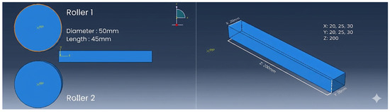
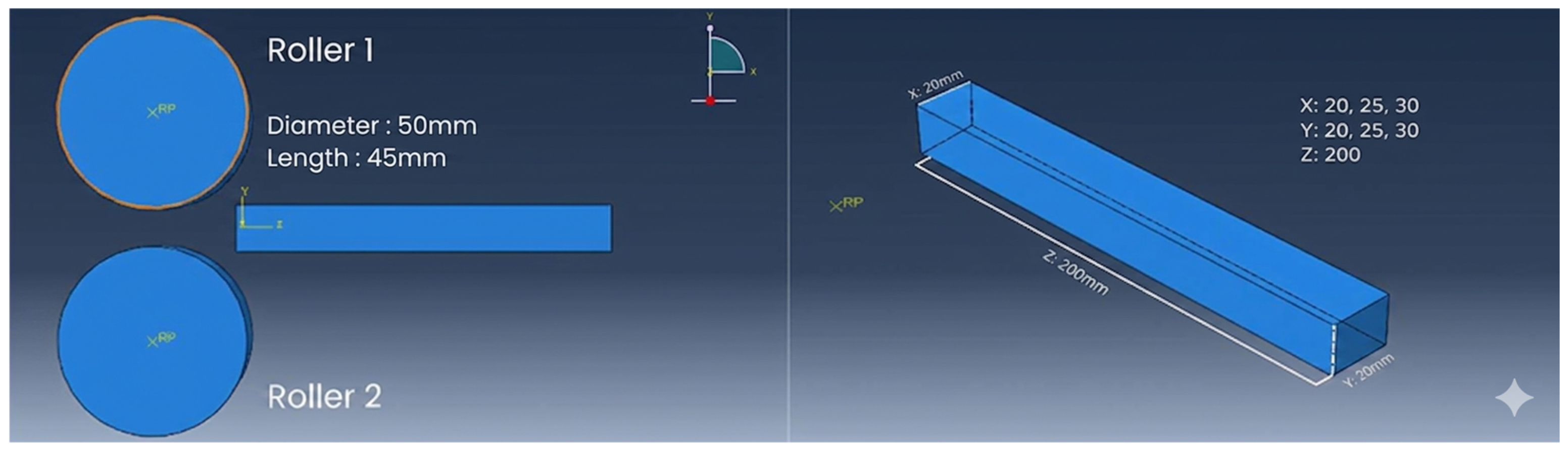
This research is designed to analyze the metal rolling process numerically using the Finite Element Method (FEM). The model consists of two symmetrically placed rollers with a diameter of 50 mm and a length of 45 mm, as well as a steel block as the workpiece. The variations of the cross-sectional dimensions of the block used are 20 × 20 × 200 mm, 25 × 25 × 200 mm, and 30 × 30 × 200 mm, as shown in Figure 1.
Figure 1.
3D model of the roller and specimen.
The selection of these variations aims to evaluate the effect of cross-sectional size on stress, strain, and displacement distribution during the plastic deformation process. Abaqus/CAE was chosen due to its advantages in nonlinear modeling, contact analysis, and detailed deformation visualization, making it capable of accurately representing the rolling phenomenon. The upper roller functions as the main pressure applicator, while the lower roller serves as a support, allowing the model configuration to represent two-directional rolling conditions effectively.
2.2. Rolling Process
The rolling simulation process was carried out through several structured stages to ensure that the analysis accurately represents actual conditions. The initial stage consisted of the geometric modeling of the rolling system, which included two rollers with a diameter of 50 mm and a length of 45 mm, as well as a steel workpiece modeled as a rectangular billet with three cross-sectional configurations: 20 × 20 × 200 mm, 25 × 25 × 200 mm, and 30 × 30 × 200 mm. After the geometric modeling stage, the steel material properties were characterized by defining parameters such as density, elastic modulus, and plastic constitutive behavior, thereby enabling a more realistic simulation of the material’s mechanical response.
The model was assembled in the assembly module, where the upper roller was positioned as the press and the lower roller as the support, arranged symmetrically to ensure balanced plastic deformation. The interaction between the rollers and the block was then defined using a surface-to-surface contact approach, which represents the direct contact phenomenon in the nip zone. This stage is crucial, as the accuracy of the contact definition determines the distribution of stress and strain during the rolling process.
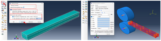
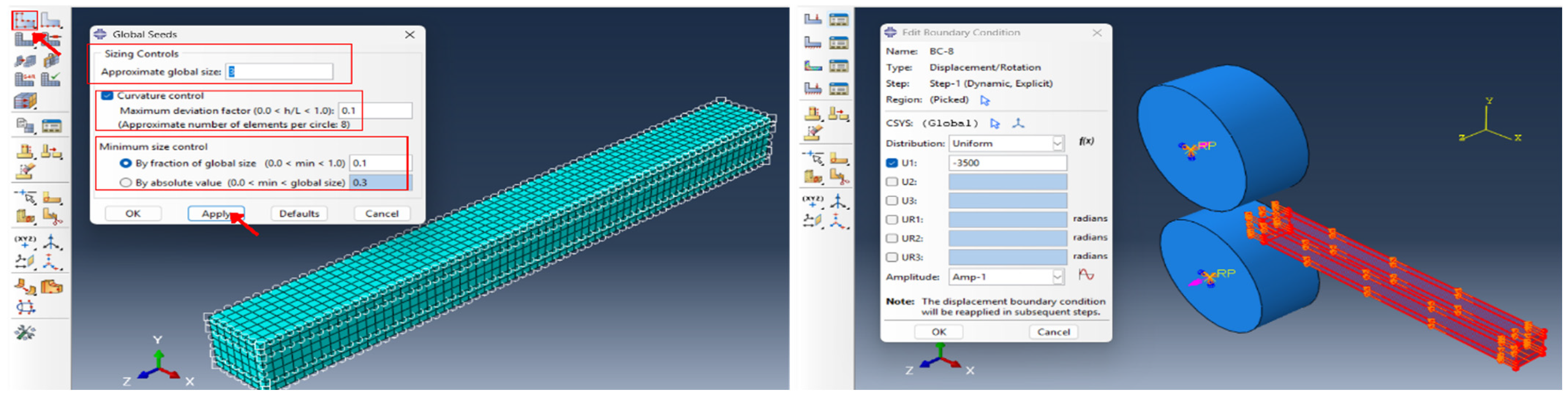
The next process involved dividing the model into discrete elements with sizes adjusted to achieve a balance between result accuracy and computational efficiency. Afterward, boundary conditions were defined by applying rotation to the upper roller while constraining specific movements of the lower roller. These boundary conditions were applied to generate a simultaneous compressive force that induces plastic deformation in the block according to the rolling mechanism. A series of FEM simulation setup procedures is presented in Figure 2.
Figure 2.
Meshing of the workpiece and application of boundary conditions on the rollers and workpiece.
3. Results and Discussion
3.1. Stress Distribution Analysis
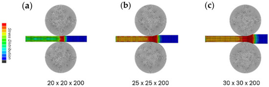
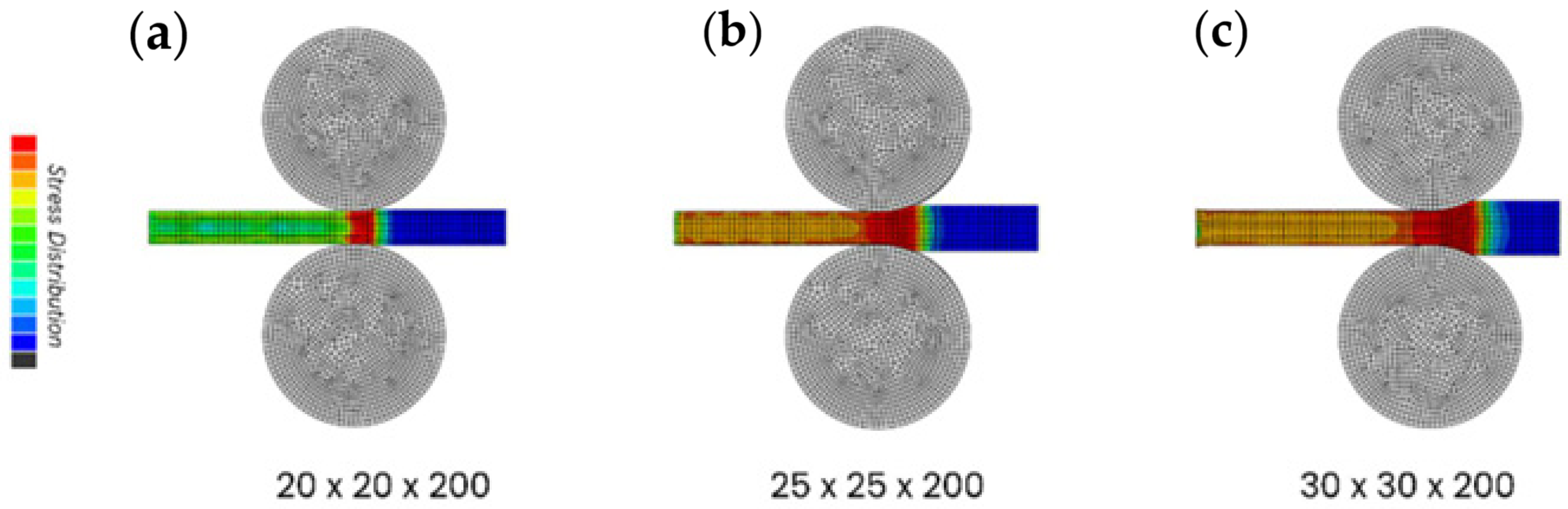
Stress is a key parameter in the rolling process, as it determines the material’s response to the compressive load applied by the rollers. The stress magnitudes are greatly influenced by the cross-sectional dimensions of the workpiece and the contact conditions in the nip zone. The stress distribution analysis for the three variations of workpiece dimensions is shown in Figure 3.
Figure 3.
Stress distribution for different dimension variations.
Figure 3 shows that for the 20 × 20 × 200 mm dimension, the maximum stress is approximately 399.7 MPa, concentrated in the contact area with a dominant red color at the edges of the workpiece, while the central region exhibits stress magnitudes ranging from 200–320 MPa with green-yellow gradients. This indicates that plastic deformation is still concentrated in specific regions.
For the 25 × 25 × 200 mm dimension, the maximum stress increases to 412 MPa, with a more uniform distribution along the cross-section. The dominant yellow-orange color represents a range of 300–400 MPa, indicating a wider spread of plastic deformation compared to the previous size.
Meanwhile, for the 30 × 30 × 200 mm dimension, the maximum stress reaches 460 MPa, showing the most comprehensive distribution pattern. The nip zone remains the main area of stress concentration; however, the color transition from blue to red demonstrates a more homogeneous plastic deformation across the entire cross-section.
Overall, the simulation results confirm that as the cross-sectional dimension increases, the stress distribution tends to become more uniform and the plastic deformation zone expands. This finding highlights the importance of controlling the workpiece dimensions and operational parameters to achieve a more optimal rolling outcome.
3.2. Strain Analysis
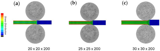
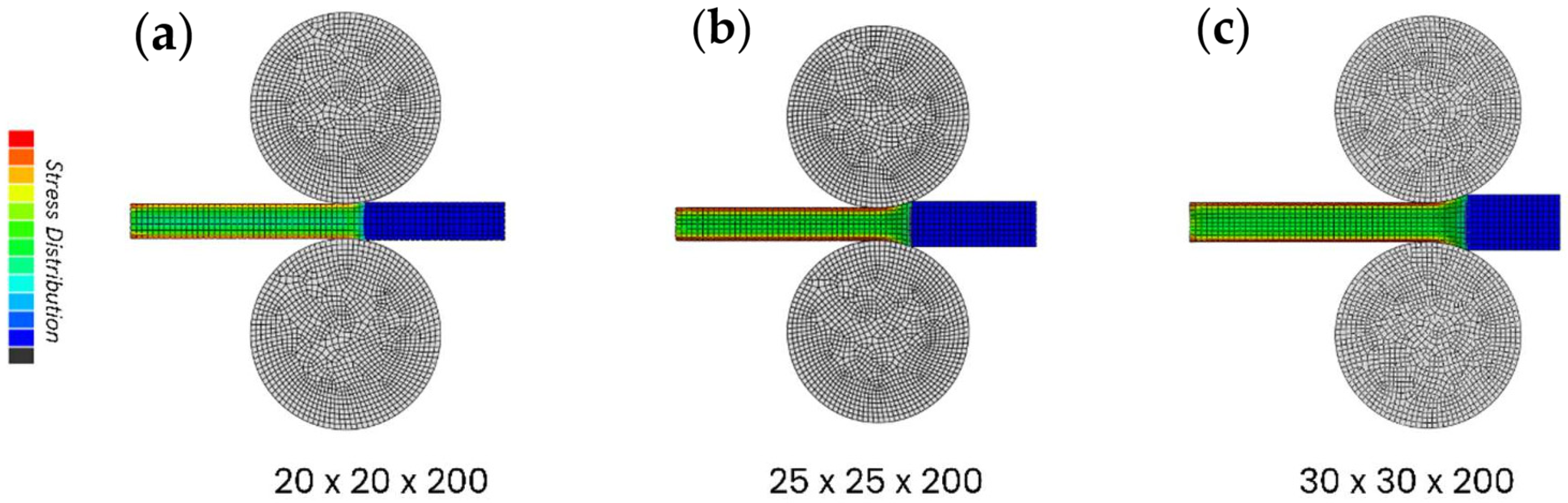
Strain in the rolling process reflects the intensity of plastic deformation caused by the pressure exerted by the rollers. The magnitude of strain is highly influenced by the cross-sectional dimensions and the distribution pattern of forces in the contact zone. The simulation results of strain distribution for the three variations of workpiece dimensions are shown in Figure 4.
Figure 4.
Strain distribution for different workpiece dimension variations.
For the 20 × 20 × 200 mm dimension, the maximum strain reaches approximately 152,000 µstrain, with the main concentration in the contact zone. The dominant red color in this area indicates high strain, while the central region is represented by green-yellow gradients ranging from 26,000 to 80,000 µstrain. This pattern suggests that the deformation is still localized and has not yet spread uniformly.
For the 25 × 25 × 200 mm dimension, the maximum strain increases to 597,200 µstrain with a more even distribution. The dominant yellow-orange color along the cross-section indicates that plastic deformation has extended to a wider area. This condition confirms that a larger cross-section is capable of distributing loads more evenly.
Meanwhile, for the 30 × 30 × 200 mm dimension, the maximum strain reaches approximately 723,800 µstrain. The highest concentration remains in the nip zone; however, the orange-red color distribution covers almost the entire cross-section. This distribution illustrates the most homogeneous plastic deformation, meaning that larger workpieces tend to undergo more complete shape changes compared to the smaller variations.
4. Conclusions
Based on the numerical simulation using the finite element method for three variations of workpiece dimensions, namely 20 × 20 × 200 mm, 25 × 25 × 200 mm, and 30 × 30 × 200 mm, several conclusions can be drawn as follows:
The maximum stress is always located in the roller contact area, with a wider distribution and increased intensity as the cross-sectional dimension increases.
The maximum strain is concentrated in the contact zone; however, its distribution becomes broader and more uniform for larger cross-sectional dimensions.
The larger the workpiece cross-section, the wider the distribution of stress, strain, and displacement formed. Therefore, proper adjustment of process parameters is required to maintain stable plastic deformation.
Author Contributions
Conceptualization; methodology; formal analysis; software; writing—original draft preparation; supervision, S.H.P.; validation; investigation; writing—review and editing; supervision, J.P.; resources; data curation; D.D.A. All authors have read and agreed to the published version of the manuscript.
Funding
This research was funded by the Universitas Muhammadiyah Kalimantan Timur.
Institutional Review Board Statement
Not applicable.
Informed Consent Statement
Not applicable.
Data Availability Statement
The data presented in this study are available on request from the corresponding author.
Acknowledgments
The authors would like to express their sincere gratitude to the Faculty of Science and Technology, Universitas Muhammadiyah Kalimantan Timur, for the continuous support, facilities, and guidance provided throughout this research. The resources and academic environment offered by the faculty have greatly contributed to the successful completion of this study. And also for Universitas Darma Persada, for supporting this research.
Conflicts of Interest
The authors declare no conflicts of interest.
References
- T, D.R. Steel as a Sustainable Material: A Discussion. Int. J. Innov. Res. Eng. Manag. 2018, 5, 7–9. [Google Scholar] [CrossRef] [Scilit]
- Bhardwaj, A.R.; Shrivastva, K.S. Rolling Process in Metal Forming: A Brief Review. Int. J. Res. Appl. Sci. Eng. Technol. 2024, 12, 115–116. [Google Scholar] [CrossRef] [Scilit]
- Kumar, A.; Rath, S.; Kumar, M. Simulation of plate rolling process using finite element method. Mater. Today Proc. 2021, 42, 650–659. [Google Scholar] [CrossRef] [Scilit]
- Ali, S.S.; Mangshetty, S. Finite Element Analysis of Evolution of Defects During Rolling. Int. J. Eng. Res. Technol. 2013, 2, 1937–1943. [Google Scholar]
- Song, J.; Lan, J.; Zhu, L.; Jiang, Z.; Zhang, Z.; Han, J.; Ma, C. Finite Element Simulation and Microstructural Analysis of Roll Forming for DP590 High-Strength Dual-Phase Steel Wheel Rims. Materials 2024, 17, 3795. [Google Scholar] [CrossRef] [Scilit] [PubMed]
- Theilen, E.; Rörich, A.; Lange, T.; Bendak, S.; Huber, C.; Schmal, H.; Izadpanah, K.; Georgii, J. Validation of a Finite Element Simulation for Predicting Individual Knee Joint Kinematics. IEEE Open J. Eng. Med. Biol. 2023, 5, 125–132. [Google Scholar] [CrossRef] [Scilit] [PubMed]
- Rosyidah, A.; Edistria, E.; Wijaya, B.S. Simulation of Mechanical Connection Models Using Couplers for Precast Concrete. Media Komun. Tek. Sipil 2023, 29, 141–150. [Google Scholar] [CrossRef] [Scilit]
Disclaimer/Publisher’s Note: The statements, opinions and data contained in all publications are solely those of the individual author(s) and contributor(s) and not of MDPI and/or the editor(s). MDPI and/or the editor(s) disclaim responsibility for any injury to people or property resulting from any ideas, methods, instructions or products referred to in the content. |
© 2026 by the authors. Licensee MDPI, Basel, Switzerland. This article is an open access article distributed under the terms and conditions of the Creative Commons Attribution (CC BY) license.