Proceeding Paper

Electro-Heating of Polymer Nanocomposites for Aeronautical Composite Structures †

1
Department of Industrial Engineering, University of Salerno, Via Giovanni Paolo II, 132, 84084 Fisciano, SA, Italy
2
Institute for Polymers, Composites, and Biomaterials (IPCB-CNR), Via Previati n. 1/E, 23900 Lecco, LC, Italy
3
CNR-IPCB Institute for Polymers Composites and Biomaterials, Consiglio Nazionale delle Ricerche, P.le E Fermi 1, 80055 Portici, NA, Italy
4
Department of Engineering, University of Campania “Luigi Vanvitelli”, Via Roma 29, 81031 Aversa, CE, Italy
5
A.T.M.—Advanced Tools and Moulds srl, Zona Industriale EX-INDESIT Stab. 15, 81030 Aversa, CE, Italy
*
Author to whom correspondence should be addressed.
Presented at the 15th EASN International Conference, Madrid, Spain, 14–17 October 2025.
Eng. Proc. 2026, 133(1), 67; https://doi.org/10.3390/engproc2026133067
Published: 5 May 2026

Abstract

This work presents an approach for designing 3D-printed heaters with tunable electrical resistance by optimizing both printing and geometrical parameters. To this end, acrylonitrile butadiene styrene reinforced with carbon nanotubes (ABS-CNTs) has been processed through fused filament fabrication (FFF) in a manner that favors electrical current flow along the printing direction and enables adjustment of electrical resistance to meet the scalability needs and limitations of the power supplier available in the application field. The as-developed 3D-printed heater has been integrated into an aeronautical fiberglass composite as proof of its possible application as a de-icing system.

1. Introduction

Electro-thermal heating based on the Joule effect has emerged as a versatile solution for a wide range of applications, including de-icing strategies [1], out-of-autoclave processing [2,3], and welding operations [4,5]. Despite its potential, achieving uniform heat distribution, simplified design, and high energy efficiency remains challenging [6]. These objectives require materials capable of efficiently converting electrical energy into heat, as well as manufacturing processes that allow customization of heater characteristics to meet specific performance requirements and application constraints—such as available power supply, heating area, and target steady-state temperature.
Recent advancements in composite materials and additive manufacturing technologies have opened new opportunities in this field. The incorporation of conductive nanofillers (e.g., carbon nanotubes [7,8,9], graphene [10,11,12], mxene [13,14]) into polymer matrices enables the development of lightweight, flexible heating elements that can conform to complex geometries [15]. Literature reports indicate that achieving high electro-thermal efficiency typically requires adding conductive fillers beyond the electrical percolation threshold [16], which allows for significant temperature increases at relatively low applied voltages. However, this approach alone may not suffice for large-scale industrial applications, where the required voltage strongly depends on both the heater dimensions and the intrinsic electrical conductivity of the material.
Rather than solely modifying material composition, geometrical optimization of the heater design combined with careful selection of processing parameters offers a promising strategy to address these limitations. Fused filament fabrication is a 3D-printing technology capable of creating complex geometries without material waste by depositing molten thermoplastic materials layer by layer [17]. Combining the functional properties of nanocomposites with the design flexibility of additive manufacturing enables the fabrication of customized devices tailored to specific application needs.
In this context, the present work investigates design and optimization approaches for Joule-effect-based heating elements, with particular emphasis on scalability, flexibility, and energy efficiency. The aim is to propose solutions that enable integration into complex structures while ensuring reliable thermal performance under demanding operating conditions.

2. Materials and Methods

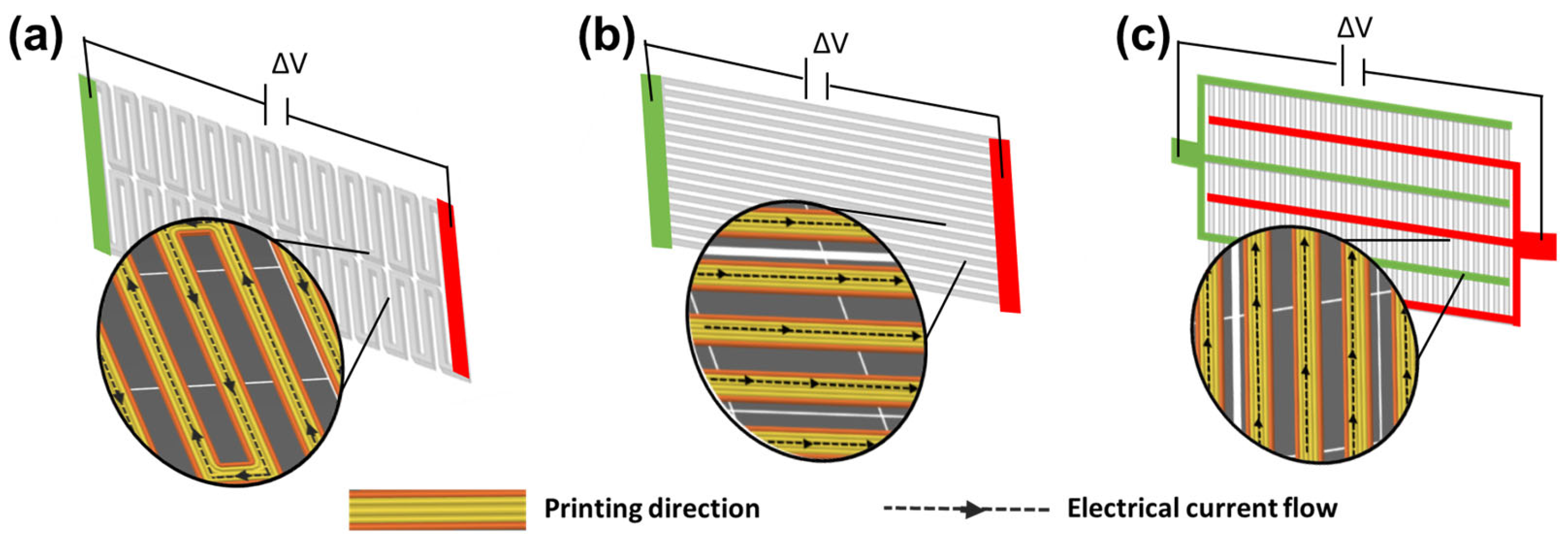
The ABS filled with carbon nanotubes (ABS–CNT) was sourced from 3DXTECH Additive Manufacturing (Grand Rapids, MI, USA) as spooled filament whose diameter was 1.75 mm. The nanofiller concentration is reported as below 10 wt% in the technical datasheet. Three distinct geometries of 3D-printed heaters were fabricated (see Figure 1) using an Original Prusa i3 MK2 3D printer (Prusa Research, Prague, Czech Republic). Printing settings were configured in Slic3r Prusa Edition (Prusa Research) and kept consistent across all tested samples. During the CAM phase, the infill pattern of the sample has been designed in such a way as to complete each geometry through concentric perimeter repetitions. Considering the position of the electrical contacts, this strategy allows the current to flow in the direction parallel to the deposited filaments (see Figure 1). In a recent work [18], the authors have demonstrated that the electrical conductivity along the printing direction is about two orders of magnitude higher than the electrical conductivity in the direction perpendicular to the printed filaments.
The other printing parameters are an extrusion temperature of 250 °C, a bed temperature of 80 °C, a nozzle diameter of 0.4 mm, an infill density of 100% and a printing speed of 80 mm/s. The layer height was set to 0.3 mm for the first layer and to 0.2 mm for the following layers. These parameters have been chosen to ensure the high quality of the final object (e.g., lower porosity [19] allowing the material to relax internal stresses [20]). To demonstrate its suitability for de-icing applications, the H3 printed heater was embedded in the middle plane of a fiberglass composite as a functional heating element. The sandwich panel consisted of four fiberglass prepreg layers (Krempel BD 2808, twill 2,2, Krempel GmbH, Vaihingen/Enz, Germany) arranged in a (0°/90°/0°/90°) stacking sequence on both sides of the embedded heater, in an oven at 80 °C for 3 h within a vacuum bag system. The selected curing cycle allowed the 3D-printed heater to be consolidated in the composite structure without softening and without losing its morphology since 80 °C is well below the glass transition temperature of ABS-CNTs, which is 110 °C [21]. The electrical characterization method and Joule heating test procedure are summarized in Table 1.

3. Result and Discussion

3.1. Electrical Characterization of 3D-Printed Heaters

Considering the position of electrical contacts (green and red areas in Figure 1), H1, H2 and H3 can be schematized as resistances composed of several resistive branches in parallel. Based on this, the overall equivalent resistance value ( R e q ) is described by the following equation:
1 R e q =   i = 1 n 1 R i
where n is the number of resistive branches in parallel and R i is the electrical resistance of each of them. If all branches have the resistance value ( R ), Equation (1) becomes:
R e q = R n
Substituting the second Ohm’s law in Equation (2), a simple model describing equal resistances in parallel is obtained as follows:
R e q = 1 n × ρ × L W × s
where ρ is the electrical resistivity of the material, L is the length, W the width and s the thickness of the sample.
In the present case, the material composition remains unchanged for all three geometries; thus, the same electrical resistivity value has to be considered. As expected from Equation (3), the total equivalent resistance can be tuned by varying the number of branches in parallel ( n ) , their length ( L ) , width ( W ) and thickness ( s ). In this way, it is possible to reduce the equivalent resistance without changing the filler concentration in the building material. This approach is particularly advantageous for 3D-printed heaters for two main reasons: (i) the free-form manufacturing easily allows for the production of customized heaters whose geometry has been optimized based on electrical resistance requirements, differing from traditional production processes requiring suitably designed molds; and (ii) it is not necessary to increase the filler concentration to reach a low resistance value, avoiding common issues during the printing such as clogging during the processing of nanocomposite materials. H1 geometry was inspired by commercially available metallic resistors. The values of n ,   L ,   W and s for H1 are reported in Table 2. However, the experimental value of R e q for the H1 sample was too high to apply H1 as a heater, since very high voltages would have been necessary to heat it. Passing from H1 to H2, the printing area occupied by the samples has been kept constant and equal to the value of 30 cm2. At the same time, to reduce the total equivalent resistance, the number of branches in parallel increased from two to 15, and their length was reduced from 73.6 cm to 10 cm. This choice resulted in lowering the total equivalent resistance by about two orders of magnitude. Although the H2 configuration demonstrates reduced electrical conductivity as expected from Equation (3) compared to H1, it was not flexible. However, flexibility remains a key factor for the integration of electro-thermal heaters into composite structures, particularly those with curved geometries (e.g., the leading edge of an airplane). To get flexibility, the thickness decreased from 2 mm to 0.5 mm. To compensate for the effect of thickness reduction on the R e q (it causes an increase in total resistance, according to Equation (3)), n was increased from 15 to 150, and L was reduced from 10 cm to 1.25 cm, while keeping the area to be heated (30 cm2) constant. H3 could be represented as a long series of 150 branches in parallel; however, by folding it and overlapping the equipotential surfaces of the electrical contacts, a more compact comb structure was obtained. The value of equivalent resistance for H3 is 30 Ω, about one order lower than the equivalent resistance of H2 and three orders lower than that of H1. The geometric parameters and the respective R e q values for H1, H2, and H3 are summarized in Table 2.
The advantage of this strategy also relies on the possibility of scaling up H3 by properly tuning the R e q value according to the area to be covered and to the power supplier available in the application field. This aspect will be clearer in the following section, where the Joule heating performance of H1, H2, and H3 is discussed.

3.2. Joule Heating Performance of 3D-Printed Heater

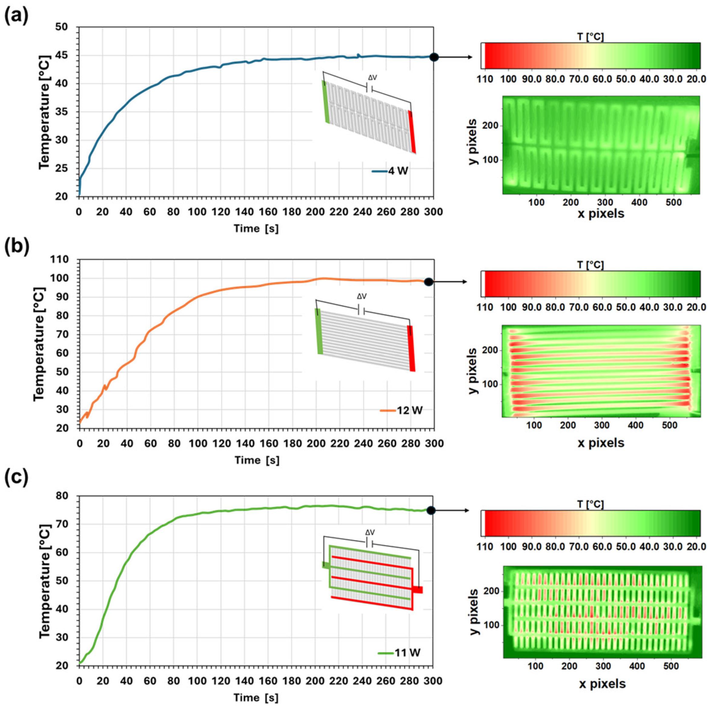
Joule heating tests have been carried out on the three experimental heaters to understand their performance in terms of the required voltage value needed to reach a determined temperature. Due to the high equivalent resistance value of H1, a high voltage value of 350 V has been applied to obtain an increase in the temperature of 25 °C (∆T) at steady-state conditions (from an initial value of 20 °C to the plateau value 45 °C). By lowering the total resistance by two orders of magnitude, passing from H1 to H2 geometry, a lower voltage value (100 V) was enough to reach a higher temperature, 97 °C, at a steady state, corresponding to a ∆T of about 77 °C. The value of the electrical power applied to H1 and H2 is summarized in Table 3 along with the applied voltage (∆V), the steady-state temperature variation (∆T), and the time needed to reach the steady-state temperature (∆tss). The temperature profiles of H1 and H2 during Joule heating tests are shown in Figure 2a and Figure 2b, respectively, together with the IR thermal camera image captured at steady-state conditions (300 s).
In the case of H3, the low value of equivalent resistance (30 Ω) allows for applying a low voltage value (18 V) to reach a steady-state temperature of about 76 °C (∆T = 56 °C). Thermal IR images reported in Figure 2a–c show a quite homogeneous temperature distribution on the surface of all three experimental 3D-printed heaters.
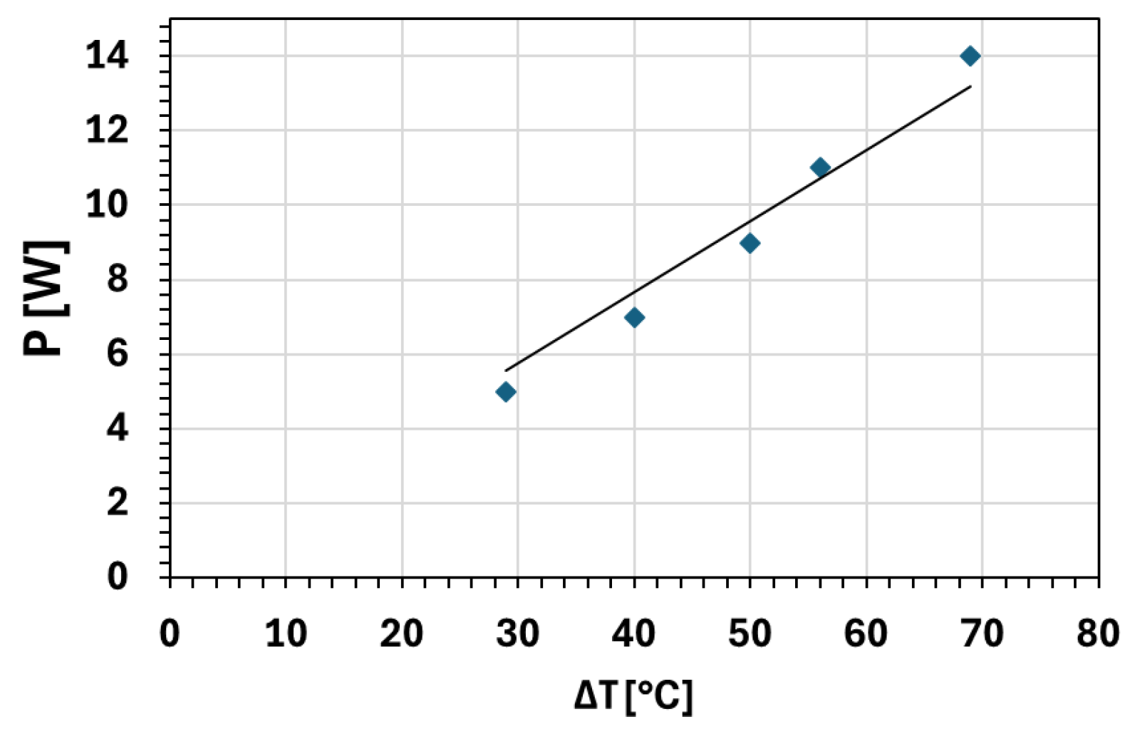
Adapting the electrical resistance to the voltage values available in the application field can be very useful. For example, when the heater is intended for use as an aircraft de-icing system, the onboard power supply typically provides voltages of 28 V or 110 V [22]. Conversely, if the same system is designed for integration into civil buildings to prevent roof icing in cold climates, the power source would generally be the domestic electrical grid—230 V in Europe and 120 V in the United States [23]. In automotive applications, the available onboard voltage is usually 12 V or 48 V [24]. Figure 3 shows how ∆T depends on the applied electrical power values. As expected from the heat balance at steady-state conditions described by Equation (4), by increasing the applied power, the steady-state temperature increases linearly.
P G = h × ( T s s T a i r ) × S
where G is the heat generated inside the sample by the Joule effect, strictly determined by the applied electrical power P , h is the heat transfer coefficient due to free convection toward the air, T s s is the steady-state temperature of the sample, and T a i r is the temperature of the surrounding ambient, while S is the exchange surface between the sample and the air.

3.3. Joule Heating Performance of the 3D-Printed Heater Integrated in the Fiberglass Structure

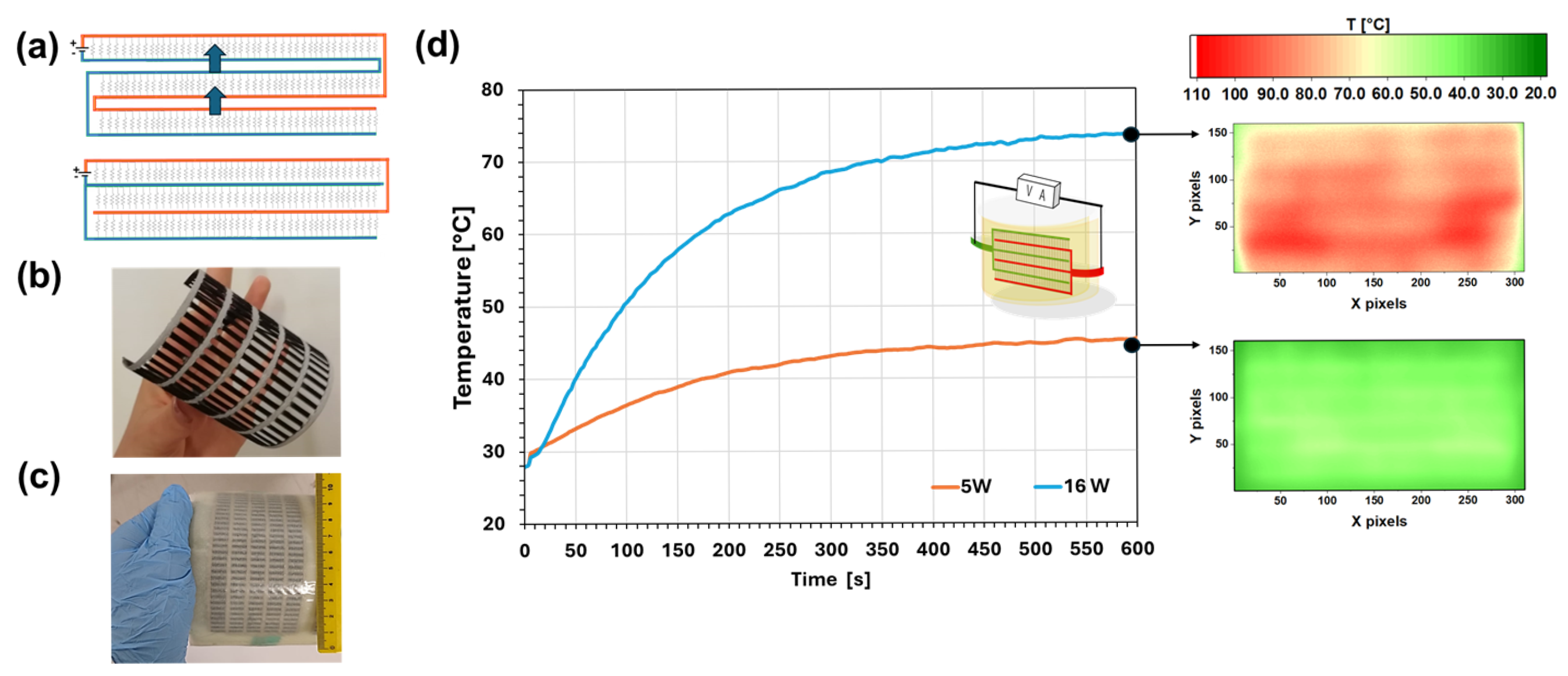
The topological optimization implemented in this study establishes a framework for designing heating elements that can be effectively scaled for large-area applications. Among the proposed configurations, H3 represents a notable example of a low-resistance heater that combines scalability with mechanical flexibility. When an increase in the heating surface is required, the comb-like architecture of H3 can be replicated following the schematic representation in Figure 4a. This modular approach allows for an increase in the number of branches, with their lengths adjusted to preserve constant equivalent resistance, as defined by Equation (3). Furthermore, the H3 configuration exhibits remarkable flexibility, as evidenced in Figure 4b, which underscores its suitability for integration in curved structures, shown in Figure 4c. Joule heating tests were repeated on the H3 integrated into the fiberglass curved structure at two different power values, 5 W and 16 W. The data obtained are reported in Figure 4d. Even in these two cases, thermal camera images at steady-state conditions show an overall homogeneous temperature distribution on the fiberglass composite. This result means that the 3D-printed heater survived the integration procedure and the curing phase without undergoing any defects.

4. Conclusions

This present paper shows a case study of the fabrication of ABS-CNT heating elements via fused filament fabrication (FFF), having tunable performance based on application-specific requirements such as target temperature, available power supply, and geometric adaptability. Firstly, 3D-printed heaters have been printed in such a way as to favor the current flowing along the printed filaments. Without changing the material composition, a design strategy regarding the electrical resistance of the 3D-printed heaters based on the model of ì resistive branches in parallel was proposed and validated. Three different electro-thermal heaters (H1, H2, and H3) have been produced following this strategy, resulting in a reduction in the equivalent resistance by about three orders of magnitude (from ~30 kΩ of H1 to ~30 Ω of H3). The optimized heater H3 was successfully integrated into a curved fiberglass composite thanks to its flexibility. These results highlight how, by properly combining the smart function of nanocomposite materials (e.g., electro-thermal heating) with the 3D-printing potential (e.g., free-form fabrication), it is possible to produce customized devices meeting application requirements.

Author Contributions

Conceptualization, F.A. and L.G.; methodology, F.A., L.V. and R.P.; software, B.P.; validation, L.V.; formal analysis, F.A., B.P. and A.M.; investigation, F.A. and L.V.; resources, A.S. and G.D.T.; data curation, F.A., A.S., B.P., R.P. and A.M.; writing—original draft preparation, F.A.; writing—review and editing, F.A., L.V. and L.G.; visualization, R.P.; supervision, L.G.; funding acquisition, L.G. All authors have read and agreed to the published version of the manuscript.

Funding

This research was supported by the Italian Ministry of University and Research—PRIN 2022 project “Integration of Continuous Fibers and Self-healing agents in 3D printed thermoplastic composites (INFINITE)” (Prot. 2022AK TCPH).

Institutional Review Board Statement

Not applicable.

Informed Consent Statement

Not applicable.

Data Availability Statement

Data available on request due to restrictions (e.g., privacy).

Conflicts of Interest

Author Giuseppe De Tommaso was employed by the company Advanced Tools and Moulds srl. The remaining authors declare that the research was conducted in the absence of any commercial or financial relationships that could be construed as a potential conflict of interest.

References

  1. Longo, R.; Vertuccio, L.; Aliberti, F.; Raimondo, M.; Pantani, R.; Russo, S.; Iannuzzo, G.; Guadagno, L. Adaptative electrothermal activation of hybrid composites for anti-icing function. Adv. Compos. Hybrid Mater. 2025, 8, 268. [Google Scholar] [CrossRef]
  2. Bai, W.; Zhang, X.; Gao, C.; Zhao, X.; He, Y.; Shang, Y.; Shi, B.; Lu, L.; Chu, D. 3D printing of CNTs-modified continuous carbon fiber composites driven by Joule-heat resin curing. Int. J. Therm. Sci. 2025, 216, 110048. [Google Scholar] [CrossRef]
  3. Guadagno, L.; Vertuccio, L.; Aliberti, F.; Calabrese, E.; Raimondo, M.; Pantani, R.; Longo, R. Sustainable biobased composites manufactured via Joule heating curing with recycled carbon fibers. Compos. Part C Open Access 2025, 17, 100609. [Google Scholar] [CrossRef]
  4. Brassard, D.; Dubé, M.; Tavares, J.R. Modelling resistance welding of thermoplastic composites with a nanocomposite heating element. J. Compos. Mater. 2021, 55, 625–639. [Google Scholar] [CrossRef]
  5. Tijs, B.H.A.H.; Doldersum, M.H.J.; Turon, A.; Waleson, J.E.A.; Bisagni, C. Experimental and numerical evaluation of conduction welded thermoplastic composite joints. Compos. Struct. 2022, 281, 114964. [Google Scholar] [CrossRef]
  6. Bai, Z.; Li, Z.; Du, S.; Tian, T.; Liu, G.; Wu, H.; Zhou, H.; Liu, H. Printable and Flexible Heater with High Electric-to-Thermal Conversion Efficiency by Force and Temperature Field Controlling. ACS Appl. Mater. Interfaces 2025, 17, 57569–57577. [Google Scholar] [CrossRef] [PubMed]
  7. Dul, S.; Fambri, L.; Pegoretti, A. Filaments Production and Fused Deposition Modelling of ABS/Carbon Nanotubes Composites. Nanomaterials 2018, 8, 49. [Google Scholar] [CrossRef] [PubMed]
  8. Dul, S.; Gutierrez, B.J.A.; Pegoretti, A.; Alvarez-Quintana, J.; Fambri, L. 3D printing of ABS Nanocomposites. Comparison of processing and effects of multi-wall and single-wall carbon nanotubes on thermal, mechanical and electrical properties. J. Mater. Sci. Technol. 2022, 121, 52–66. [Google Scholar] [CrossRef]
  9. Jyoti, J.; Basu, S.; Singh, B.P.; Dhakate, S.R. Superior mechanical and electrical properties of multiwall carbon nanotube reinforced acrylonitrile butadiene styrene high performance composites. Compos. Part B Eng. 2015, 83, 58–65. [Google Scholar] [CrossRef]
  10. Dul, S.; Fambri, L.; Pegoretti, A. Fused deposition modelling with ABS–graphene nanocomposites. Compos. Part A Appl. Sci. Manuf. 2016, 85, 181–191. [Google Scholar] [CrossRef]
  11. Szewczyk, D.; Krivchikov, A.I.; Barabashko, M.S.; Dolbin, A.V.; Vinnikov, N.A.; Basnukaeva, R.; Chajewski, G.; Jeżowski, A. Universal behavior of low-temperature heat capacity of acrylonitrile-butadiene-styrene thermoplastic polymer and its composite with graphene oxide. Low Temp. Phys. 2023, 49, 593. [Google Scholar] [CrossRef]
  12. Tambrallimath, V.; Keshavamurthy, R.; Saravanabavan, D.; Koppad, P.G.; Kumar, G.S.P. Thermal behavior of PC-ABS based graphene filled polymer nanocomposite synthesized by FDM process. Compos. Commun. 2019, 15, 129–134. [Google Scholar] [CrossRef]
  13. Zhang, Y.; Zhang, G.; Ma, Z.; Qin, J.; Shen, X. Heterogeneous MXene-based films with graded electrical conductivity towards highly efficient EMI shielding and electrothermal heating. Nano Res. 2024, 17, 7264–7274. [Google Scholar] [CrossRef]
  14. Zhou, M.; Hu, Y.; Yan, Z.; Fu, H. Flexible MXene-based Janus film with superior heat dissipation capability for ultra-efficient electromagnetic interference shielding and Joule heating. Carbon 2024, 219, 118835. [Google Scholar] [CrossRef]
  15. Aliberti, F.; Sorrentino, A.; Palmieri, B.; Vertuccio, L.; De Tommaso, G.; Pantani, R.; Guadagno, L.; Martone, A. Lightweight 3D-printed heaters: Design and applicative versatility. Compos. Part C Open Access 2024, 15, 100527. [Google Scholar] [CrossRef]
  16. Longo, R.; Guadagno, L.; Aliberti, F.; Schiavo, L.; Oliviero, M.; Sorrentino, A.; Fiorentino, M.; Vertuccio, L. Exploitation of the tunneling effect for the development of self-sensing nanocomposite materials. Appl. Mater. Today 2025, 46, 102882. [Google Scholar] [CrossRef]
  17. Aliberti, F.; Oliviero, M.; Longo, R.; Guadagno, L.; Sorrentino, A. Effect of Crystallinity on the Printability of Poly(ethylene Terephthalate)/Poly(butylene Terephthalate) Blends. Polymers 2025, 17, 156. [Google Scholar] [CrossRef]
  18. Aliberti, F.; Guadagno, L.; Longo, R.; Raimondo, M.; Pantani, R.; Sorrentino, A.; Catauro, M.; Vertuccio, L. Three-Dimensional Printed Nanocomposites with Tunable Piezoresistive Response. Nanomaterials 2024, 14, 1761. [Google Scholar] [CrossRef]
  19. Kechagias, J.; Zaoutsos, S. Effects of 3D-printing processing parameters on FFF parts’ porosity: Outlook and trends. Mater. Manuf. Process. 2024, 39, 804–814. [Google Scholar] [CrossRef]
  20. Snapp, K.L.; Gongora, A.E.; Brown, K.A. Increasing Throughput in Fused Deposition Modeling by Modulating Bed Temperature. J. Manuf. Sci. Eng. 2021, 143, 094502. [Google Scholar] [CrossRef]
  21. Karimzadghavidel, A.; Opoz, T.T.; Mahdavinia, M.; Kiani, G.; Moradi, M. Achieving exceptional mechanical and thermal properties in ABS/MWCNTs nanocomposites with minimal CNT loading via electromechanical dispersion technique. Polym. Compos. 2025, 46, 10034–10049. [Google Scholar] [CrossRef]
  22. Schefer, H.; Fauth, L.; Kopp, T.H.; Mallwitz, R.; Friebe, J.; Kurrat, M. Discussion on Electric Power Supply Systems for All Electric Aircraft. IEEE Access 2020, 8, 84188–84216. [Google Scholar] [CrossRef]
  23. Mohammed, A.G.; Ozgur, G.; Sevkat, E. Electrical resistance heating for deicing and snow melting applications: Experimental study. Cold Reg. Sci. Technol. 2019, 160, 128–138. [Google Scholar] [CrossRef]
  24. Biba, D.-R.; Musuroi, S.; Svoboda, M. Powertrain 48V Power Supply Proposal and Safety Validation Voltage Levels for BLDC Motor Driver ASIC. In Proceedings of the 2018 International Conference on Applied and Theoretical Electricity (ICATE), Craiova, Romania, 4–6 October 2018; IEEE: New York, NY, USA, 2018. [Google Scholar]
Figure 1. Representation of electrical current flow along printing direction for: (a) heater 1 (H1), (b) heater 2 (H2), (c) heater 3 (H3).
Engproc 133 00067 g001
Figure 2. Joule heating performance of (a) H1, (b) H2, and (c) H3.
Engproc 133 00067 g002
Figure 3. Temperature variation ( Δ T = T s s T a i r ) as a function of the applied power ( P ) obtained for the H3 sample.
Engproc 133 00067 g003
Figure 4. (a) Schematic representation of scalable comb-like architecture of H3; (b) authentic images of H3 sample showing its flexibility; (c) real image of H3 sample integrated in the fiberglass structure; (d) results of Joule heating tests performed on H3 integrated into a curved fiberglass structure.
Engproc 133 00067 g004
Table 1. Electrical characterization and Joule heating test methods.
Test TypeMethod/SetupEquipment UsedConditions
Electrical
properties
Two-probe method; silver paint for contacts (green and red areas in Figure 1).Silver paint (RS 196-3600, RS PRO, Corby, UK); Electrometer Keithley 6517A (0–25 V, 10 steps) (Keithley Instruments, Inc., Solon, OH, USA); Multimeter Agilent 3458A (Agilent, Santa Clara, CA, USA).Voltage sweep: from 0 to 25 V and from 25 V to 0 V (to check hysteresis).
Joule Heating TestDC mode with a constant selected voltage.Power supply EA-PSI 8360-10T (0–360 V, 0–10 A, 1000 W max) (EA Elektro-Automatik GmbH & Co. KG., Viersen, Germany); Data Logger TC-08 (Pico Technology Ltd., St Neots, UK); PicoLog software (version 6.2.8).Temperature evolution at sample center.
Static air, both sides at 25 °C.
Temperature MeasurementThermocouples and IR imaging.Type K thermocouples (Omega Engineering Ltd., Manchester, UK); IR Camera Fluke Ti401 Pro Thermal Imager (Fluke Corporation, Washington, DC, USA).Local temperature and surface temperature map.
Table 2. Geometric parameters and electrical resistance values of the three experimental 3D-printed heaters.
H1H2H3
n 215150
L [cm]73.6101.25
s [mm]220.5
W [mm]222
R e q [Ω]30,83482330
Table 3. Electro-thermal heating performance of H1, H2, and H3.
H1H2H3
R e q [Ω]30,83482330
P [W]41211
∆V [V]35010018
∆T [°C]257756
∆tss [s]160200120
Disclaimer/Publisher’s Note: The statements, opinions and data contained in all publications are solely those of the individual author(s) and contributor(s) and not of MDPI and/or the editor(s). MDPI and/or the editor(s) disclaim responsibility for any injury to people or property resulting from any ideas, methods, instructions or products referred to in the content.