1. Introduction
Titanium alloy components are widely used in the aerospace sector due to their excellent material properties, such as high specific strength and good corrosion resistance [
1]. Conventional manufacturing routes for titanium components involve high buy-to-fly (BTF) ratios, leading to high costs and energy demands. For typical part geometries, the BTF can be in a range between 6:1 and 20:1 [
2]. A promising approach in developing flexible and eco-friendly manufacturing strategies is the use of arc-based directed energy deposition (DED-Arc) processes. These processes facilitate the creation of large-scale near-net-shape geometries, significantly minimizing material waste and enhancing sustainability [
3].
The approach of using DED-Arc near-net-shape preforms in combination with machining post processing has been widely used in research [
4], leading to the first qualified structural titanium components in aerospace [
5], underlining its potential. The flowforming (FF) process is a manufacturing alternative for thin-walled precision hollow parts with excellent mechanical properties [
6]. Currently used machined preforms made from β titanium alloys, such as Ti-15-3-3-3, face similar challenges with unsatisfactory BTF ratios. Furthermore, titanium alloys such as Ti-15-3-3-3 are often not available on the market as round material, thus excluding this material from the flowforming process. Therefore, there is also a general shortage of experience with flowforming Ti-15-3-3-3. However, their formability, a characteristic of β titanium materials, makes them well-suited for FF. In comparison, Ti-6Al-4V lacks the required deformation capability. Despite the advantages of DED-Arc, its application in producing preforms from β titanium alloys remains underexplored. In particular, the use of DED-Arc has been predominantly focused on production of Ti-6Al-4V for structural aerospace components [
7].
Balachander et al. showed that Ti-15-3-3-3, as a metastable β titanium alloy, exhibits well-controlled melting and solidification behavior during gas tungsten arc welding (GTAW), with only limited microstructure degradation despite high thermal gradients [
8]. Neves et al. are to the authors’ knowledge the first and, so far, the only authors to describe processing of the β-titanium alloy Ti-15-3-3-3 in the DED-Arc process [
9]. In their study, 3 mm thick rods were used as filler material; these can be processed using the plasma arc welding process variant. The material was successfully processed, and a fully β phase matrix was produced, indicating good processability for additive manufacturing in principle. The question of whether the resulting semi-finished products can be formed in β titanium has not yet been answered; however, the approach of combining DED-Arc manufactured preforms with an FF process was reported in [
10], where steel and stainless alloys were used.
This paper aims to establish a hybrid manufacturing route for Ti-15-3-3-3, including DED-Arc and FF, to achieve a significant reduction in material used. In addition, the study aims to contribute to a possible expansion in the range of materials for DED-Arc processes—away from conventional α/α + β titanium alloys and toward β alloys, which combine attractive properties in terms of structural mechanics and manufacturing technology for lightweight construction and complex geometries.
2. Materials and Methods
The hybrid manufacturing route, including DED-Arc and FF, was showcased on a simplified cylindrical demonstrator part. As a first step, the wire feedstock was processed through DED-Arc, using a titanium grade 2 baseplate. The feedstock consisted of Ti-15-3-3-3 welding wire of 1.2 mm diameter. The chemical composition of the wire, as stated by the material supplier (see
Table 1), remained in the standardized range. The near-net-shape build was detached from the baseplate by wire electrical discharge machining (EDM). A turning process led to a refined preform with an inner diameter of 63 mm, an outer diameter of 80 mm, and a height of 120 mm, which was finally processed by FF.
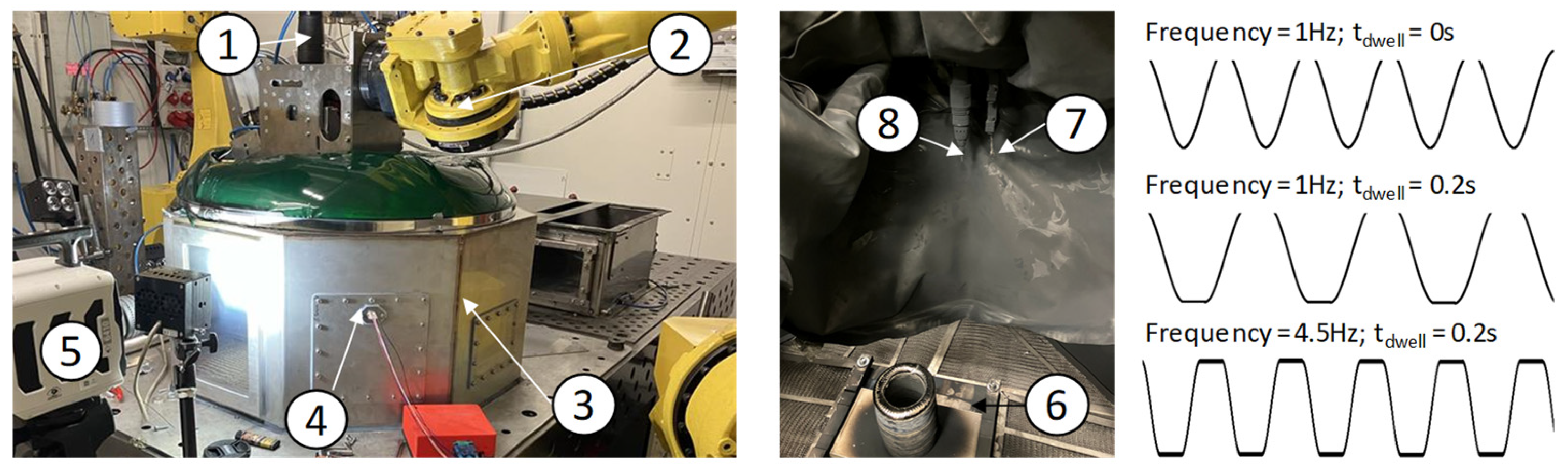
The DED-Arc process setup consisted of a Fronius TPSi400 (Fronius International GmbH, Pettenbach, Austria) welding source with Robacta torch, a Fanuc M710iC-50 (FANUC CORPORATION, Yamanashi, Japan) 6-axis handling robot and a sealed inert-gas chamber (see
Figure 1), purged with argon 4.6. The oxygen level was maintained below 250 ppm during the build-up, and was constantly monitored. An actively cooled clamping plate provided constant heat dissipation within the chamber. The interpass temperature was set to 200 °C and monitored via a thermocouple automatically placed on the surface of the most recently deposited layer. The deposition resumed once the temperature fell below 200 °C. An optical monitoring of the process was performed with a high-speed camera, orientated with a side-on view of the process.
A sinusoidal path planning strategy was selected to promote an even weld with good surface quality for the near-net-shape build. To provide sufficient machining allowance, an amplitude of 6 mm and an oscillating frequency of 2.5 Hz around a diameter of 71.5 mm was specified in the path planning. The interlayer dwell time of the sinusoidal function in the robot was used to modulate the material deposition along the radius. On the basis of preliminary experiments, an inner dwell time of 0.2 s and an outer dwell time of 0.45 s were set. The main influence of the oscillating parameters on the surface quality of the build is shown in [
11]. Furthermore, the effect of different dwell times and frequencies is illustrated in
Figure 1. These results were used to derive a suitable sinusoidal path for the cylindrical form. For each layer, four circular sections were programmed, allowing rotation of the starting point of the weld by 90° for each new layer. Before the start of a new layer, the actual build height was automatically updated, using the tip touch function of the wire on one point of the surface, allowing constant wire stick-out to be maintained.
A robot travel speed of 19 cm/min on the circular path was used, and the wire feed rate was set to 12 m/min, using the Fronius cold metal transfer (CMT) process option. Within the scope of the present work, five preforms were manufactured: one for material characterization, and four to evaluate different FF strategies. The near-net-shape build was characterized through cross-section micrographs along the entire height. The surface of the outer side of the build was measured with profilometry, using a Keyence VR6200 (KEYENCE CORPORATION, Osaka, Japan) setup. Hardness measurements (HV5) were conducted on three sections—low, middle and top—of the near-net-shape build, as well as the flowformed part.
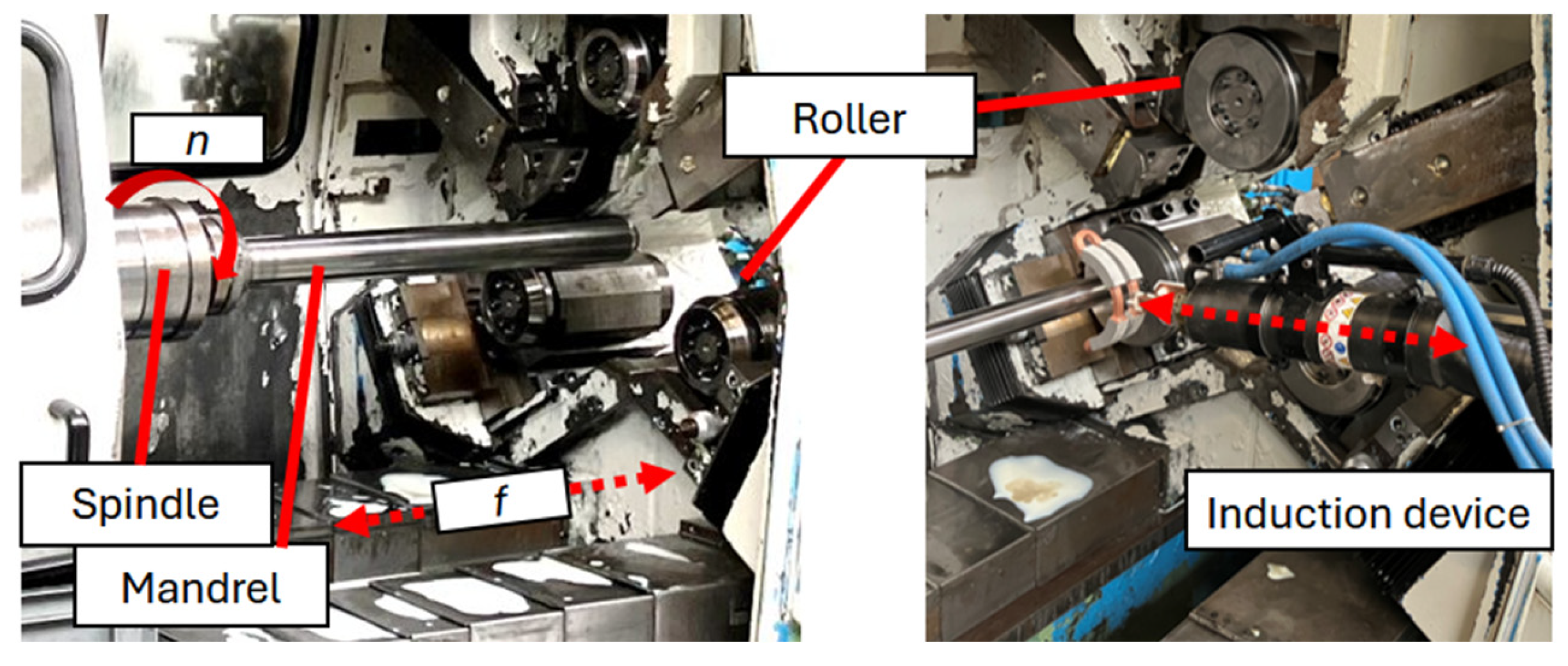
The FF process, whether backward or forward, was performed with a Leifeld ST-33( ST-33, Leifeld Metal Spinning GmbH, Ahlen, Germany) FF machine (see
Figure 2). The process was mainly controlled by the feed ratio
f between the rotational speed
n of the workpiece and the feed speed
v of the rollers. In addition to cold forming, this experimental machine is also capable of hot forming. A movable induction device was used to apply heat to the workpiece, and the device was operated by an Eldec MF 50 (50 kW) (EMAG eldec Induction GmbH, Dornstetten, Germany) induction generator.
An additional necessary pre- and post-processing step for FF was heat treatment in furnaces. This included solution annealing, stress relief annealing, and aging, and was performed with a Schmetz IU 210 (IVA Schmetz GmbH, Menden, Germany) vacuum chamber furnace.
3. Results and Discussion
3.1. DED-Arc
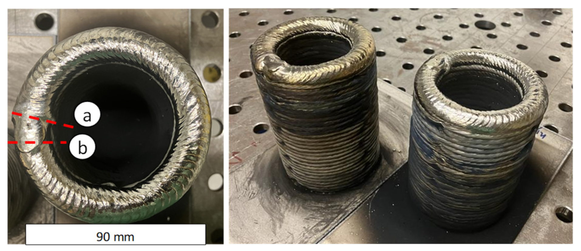
The defined parameter set led to a continuous deposition along the radius as well as along the circular path of the cylindric preform, showing a sufficient combination of dwell times and frequency for the chosen cylindric preform diameters. For the defined path and parameter set, the build led to an inner diameter of 53 mm and an outer diameter of 90 mm (see
Figure 3), resulting in a machining allowance of 5 mm on the inner and outer faces. The overall height was 124 mm, in 32 layers, with a mean layer height of 3.9 mm.
After deposition of each layer, the surface temperature of the previous layer was measured, to maintain a constant interpass temperature of 200 °C. The waiting time, excluding robot movements for layer-height referencing, increased from 0 s after the first layer to 28.5 s after the second, 154 s after the tenth, 245 s after the twentieth, and 259 s after the thirtieth layer. The overall build time was measured as 172 min, including 34 min of welding time, leading to a 181 cm3/h build rate including waiting and positioning, and a rate of 916 cm3/h including only welding time. This demonstrates an approach that enables an attractive production scenario in which multiple preforms can be manufactured within a single build job.
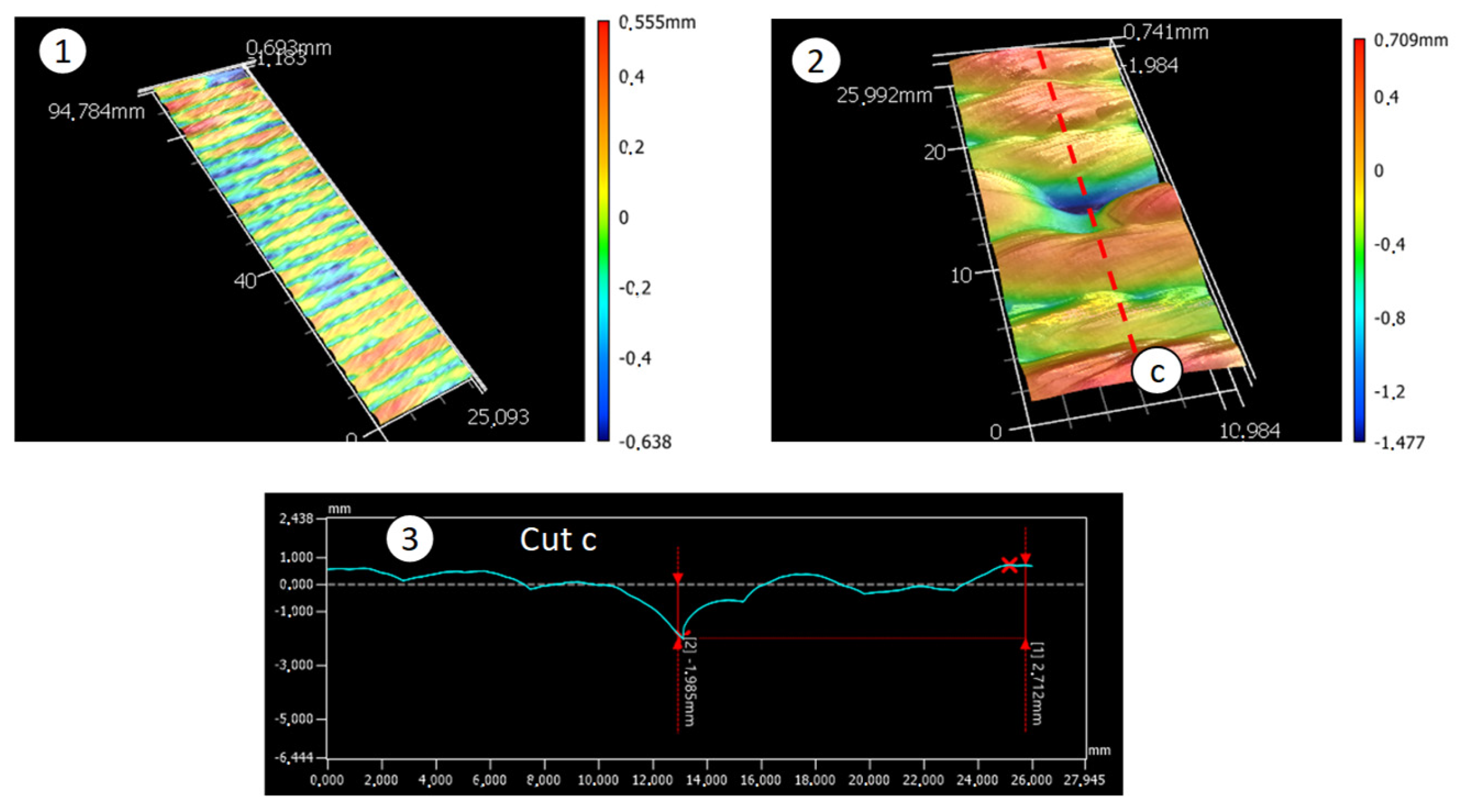
The measurement of the surface revealed a continuous quality, except for the areas at the start and end points of the weld. Exemplary areas with and without start and end points are shown in
Figure 4. The diameter of the build was compensated for with the Keyence VR-6000 series software, and the resulting projection was used for the comparison of the different areas. A typical profile in the area without start and end point revealed a maximum distance of 1.5 mm between the highest and lowest measured points.
Dents were present at each start and end point, despite the rotation after each layer. The area around the start and end point is therefore crucial for the definition of the machining allowance. The end point of the weld overlapped the starting point by 5°, to allow increased material deposition in this area. This overlap was not sufficient to prevent the dents, however. A limiting factor for prevention resulted from the path planning options. Because of robot restrictions, each start and end point was located exactly in the middle of the cylinder. This means that an alternative option, to increase the welding end time after the stoppage of the robot, might not necessarily result in the needed material deposition on the outer and inner diameters. In additional studies, further optimization of the start and end parameters is needed. The current approach resulted in dent depths in a range of 2 mm, which is still acceptable in comparison to the machining allowance.
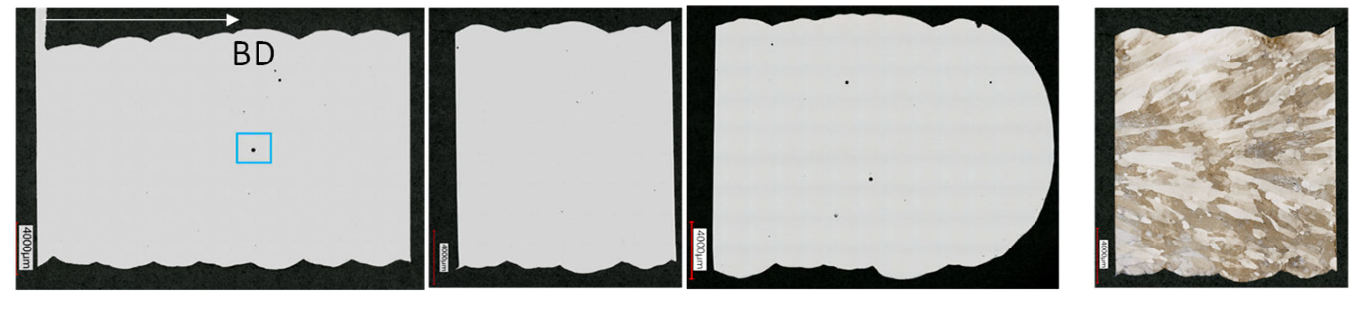
Cross-section micrographs were evaluated along the entire height in two cuts (see
Figure 3). The evaluation revealed a mean porosity of 0.016%, with the largest pore measuring 287 µm. The entire height was separated into five micrographs for each cut.
Figure 5 shows three sections, namely, low, middle, and top of cut a. The observed pores showed a circular shape with a random distribution, indicating gas pores. A detailed analysis of the chemical composition was not conducted within this study. A similar amount of gas porosity was not observed in previous studies using Ti-6Al-4V with DED-Arc [
11,
12,
13,
14,
15]. Most likely, the porosity was caused by the tin shares in the alloy, due to the low melting point of tin and the risk of vaporization during the welding process. The effect was also observed in [
16] during processing of a β titanium alloy with tin share with electron- and laser-based powder bed fusion processes. A similar impression of pores was observed in [
9] using DED-Arc and Ti-15-3-3-3, though the porosity in cross-section micrographs was not discussed.
The defined parameter set with a high deposition rate led to columnar β grains with a typical grain growth for DED-Arc across multiple layers (
Figure 5, right). Hardness measurements along the entire build height showed a mean value of 260 HV5 with a standard deviation of 7 HV5. A significant deviation in the values along the build height or width was not observed, meaning that the increased cooling time in higher layers showed no influence. As reference, a sheet of Ti-15-3-3-3 metal had a measured hardness of 248 HV5 ±5.5.
3.2. Flowforming
DED-Arc builds, machined to high precision preforms, have been used for different FF approaches. Within this study, only the backward FF method was investigated. Due to the limited knowledge available on FF of Ti-15-3-3-3, four different approaches were initially developed and investigated.
The first approach (FF 1) used no heat treatment before FF, and involved a reduction in two passes with high feed ratio
f. The second approach (FF 2) included a stress relief heat treatment before FF, and involved a reduction in two passes with high feed ratio
f. The settings of the second approach, with additional excessive cooling and a low feed ratio
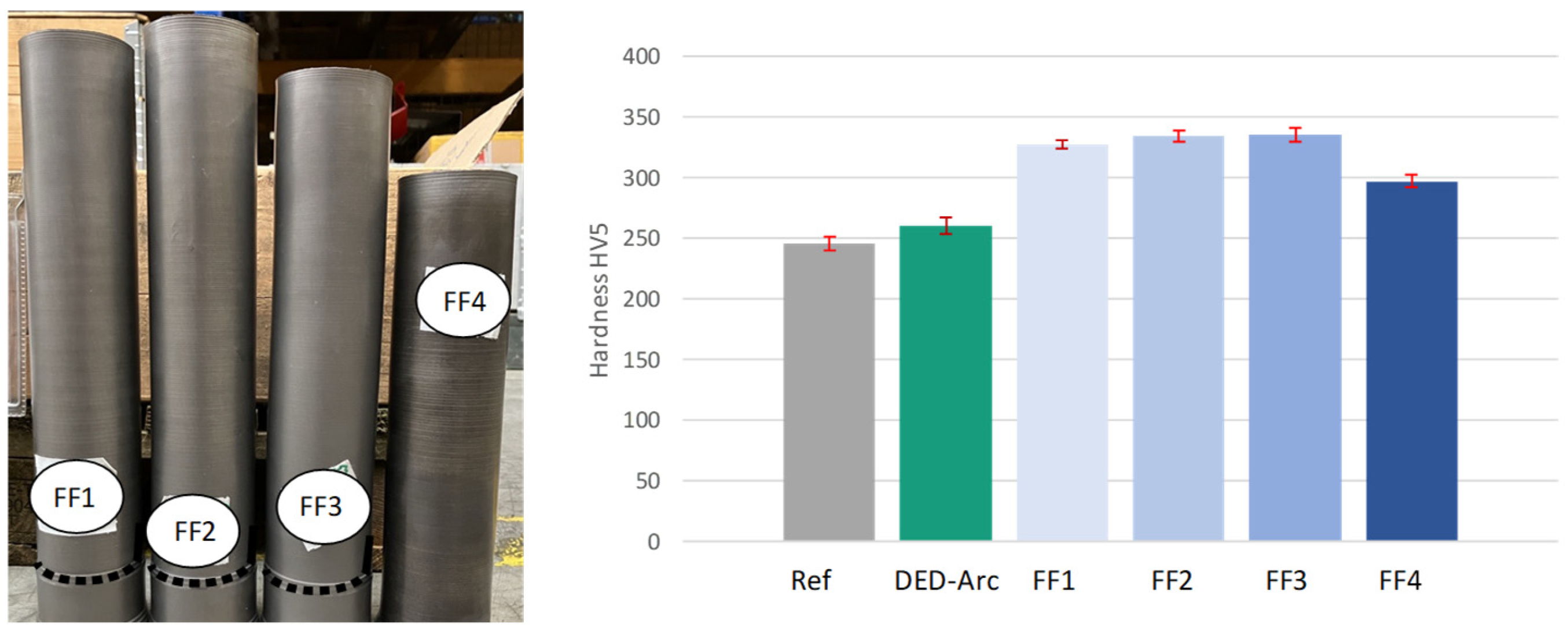
f during the FF process, led to the third approach (FF 3). The fourth approach (FF 4) tested a high reduction within one pass without previous heat treatment. All approaches yielded flowformed specimens without any defects that caused process interruptions (see
Figure 6, left). Furthermore, a reduction in wall thickness of 80% was achieved. The optical inspection revealed multiple voids and cracks on the surface of specimen FF3 in comparison to the other specimens (FF1, FF2, FF4), indicating a negative effect of the excessive cooling on deformation behavior. Contrarily, this indicated that increased energy input is required to achieve the necessary formability of the DED-Arc-processed Ti-15-3-3-3 preforms.
In a more detailed analysis of the specimens, using-cross section micrographs, each of 20 mm length, from the low, top and middle sections, several pores were observed. Pores were already present in the preforms (see
Figure 5), and were deformed within the FF process. The hydrostatic compression stress state typical of the backward FF process prevents the pores from causing structural failure; it can even be assumed that the pores were closed off under this hydrostatic compressive stress state and high energy input. This aspect will therefore be investigated in detail in further work.
The evaluation of hardness showed comparable values for all two-pass FF approaches, with a maximum value of 335 HV5 for FF3 specimens. The FF4 approach using only one pass for material reduction led to a significantly lower value of 297 HV5, which can be attributed to the increased heat input. However, in comparison to DED-Arc-preform hardness, all FF approaches showed a successful increase in hardness (see
Figure 6, right). This indicates that a controlled energy input can be utilized to control mechanical properties, and this is also to be investigated in future work, using the induction device (see
Figure 2, right).
3.3. Hybrid Manufacturing Route and Material Usage
Material usage was assessed across all manufacturing steps. In the first iteration of the near-net-shape preform, the machining allowance was larger than necessary. Surface dents of up to ~2 mm depth were observed; these can be reduced by optimizing path planning and weld start/stop parameters. In a second iteration, preforms were printed with reduced diameters to lower the machining allowance. For the defined demonstrator geometry, this reduced wire feedstock consumption to 1.95 kg, with negligible material waste during DED-Arc. Using wire EDM to detach the DED-Arc build allows multiple reuses of the titanium substrates, leading to a 0.25 kg estimate of substrate-related waste per build. Finish turning of the final preform geometry generated an additional 1.38 kg of waste. In FF, a small process-initialization area is required, adding 0.20 kg. The resulting hollow sub-part weighs 0.87 kg, corresponding to a buy-to-fly (BTF) ratio of 2.5:1 for the considered manufacturing route.
A clear advantage of this approach is the flexibility to tailor the diameter to the geometry of each end part. In conventional preform manufacturing, reliance on standard geometries leads to substantial machining volumes, especially at larger diameters. Life cycle assessments considering DED-Arc and titanium have identified primary-material production as the dominant cradle-to-gate impact, underscoring the importance of alternative manufacturing routes for titanium [
17,
18].
4. Conclusions
In this study, the processability of Ti-15-3-3-3 in a hybrid manufacturing route, including DED-Arc and flowforming (FF), was investigated and successfully demonstrated. The work was driven by the limited research conducted to date in this particular field, and underlines the potential for future advanced manufacturing applications with enhanced BTF. The following conclusions were drawn:
The DED-Arc process showed a high and repeatable process stability during the manufacturing of Ti-15-3-3-3 cylindrical preforms. As a main process anomaly, a low porosity of 0.016% was measured in cross-section micrographs.
Adapted oscillating path planning strategies for cylindrical forms led to high deposition rates of above 900 cm3/h, considering the arc-on time, in combination with a high process-specific surface quality.
DED-Arc preforms in Ti-15-3-3-3, and thus also Ti-15-3-3-3 preforms in general, were successfully processed in FF. An important finding is that material-specific flow forming strategies are required. In parallel with an improvement in formability, the developed strategies led to an increase in hardness of up to 28% compared to the DED-Arc preforms and the reference material.
The consideration of the material usage along the hybrid manufacturing route revealed the potential for BTF up to 2.5:1, clearly surpassing conventional approaches.
The study at hand lays a foundation for using DED-Arc in combination with FF, paving the way for further investigations and revealing new opportunities for advanced manufacturing routes in aerospace applications. Future work is recommended to understand in more detail the effects of different structural properties, heat-treated conditions, and induction-controlled heat inputs on FF processability. Furthermore, a detailed material characterization of both phases, DED-Arc and FF, is needed to extensively classify the material characteristics. Additional FF methods, such as forward FF and shear forming approaches can be used to extend geometrical possibilities.





 ,
,