Proceeding Paper

A Modular Assembly Concept for Large-Volume CFRP Hydrogen Tanks for Passenger Aircraft †
1
Fraunhofer Institute for Manufacturing Technology and Advanced Materials IFAM, Wiener Straße 12, 28359 Bremen, Germany
2
Fraunhofer Institute for Manufacturing Technology and Advanced Materials IFAM, Ottenbecker Damm 12, 21684 Stade, Germany
*
Author to whom correspondence should be addressed.
Presented at the 15th EASN International Conference, Madrid, Spain, 14–17 October 2025.
Current Address: Leibniz Institute for Materials Engineering—IWT, Badgasteiner Str. 3, 28359 Bremen, Germany.
Eng. Proc. 2026, 133(1), 179; https://doi.org/10.3390/engproc2026133179
Published: 27 May 2026

Abstract

This paper presents a novel modular assembly concept for large-volume Carbon Fiber Reinforced Plastics (CFRP) hydrogen tanks, supporting the aviation sector’s transition toward sustainable propulsion. Adhering to VDI 2221 and 2222 design methodologies, four assembly concepts were developed and then evaluated by Airbus, FFT, and Fraunhofer IFAM, to determine the best fit for industrial application. The “Modular Assembly System on Linear Axes” was identified as the best solution, characterized by superior process robustness and efficiency. Utilizing dual linear axes for precise component handling and robotic guidance, this concept ensures structural integrity during joining while offering scalability and seamless integration into existing manufacturing infrastructures.

1. Introduction

The aviation sector is currently at a crossroads: while global air travel is growing rapidly, the industry faces immense pressure to reduce its environmental footprint. Without significant technological intervention, CO2 emissions from aviation are projected to triple by 2050 [1,2], conflicting with international climate goals such as the Paris Agreement and the EU Green Deal [3]. Concurrently, airlines face economic instability due to fluctuating oil prices [4], driving the search for sustainable and economically viable alternatives.
Hydrogen has been identified as a promising alternative aircraft fuel [5,6]. Its advantages include the absence of CO2 emissions during combustion and a significantly higher gravimetric energy density (120–142 MJ/kg) compared to conventional kerosene (42–46 MJ/kg). However, the predominant challenge associated with hydrogen utilization lies in onboard storage [7,8]. Due to its substantially lower volumetric energy density relative to kerosene, integration within the wing structure is technically infeasible. The available internal wing volume cannot accommodate the fuel quantity required to meet standard mission profiles [9].
In general, storage density increases with rising pressure and decreasing temperature. High-pressure storage of gaseous hydrogen (GH2) entails considerable explosion risks and provides markedly lower gravimetric and volumetric efficiencies than liquid hydrogen (LH2) [10,11]. Consequently, the most viable solution for onboard storage is cryogenic storage, in which hydrogen is maintained in liquid form at extremely low temperatures (–253 °C) [7,12,13]. Such systems necessitate the development of large-volume, highly insulated tank architectures, typically featuring a double-walled configuration consisting of an inner vessel, surrounding insulation layers, and an outer shell to minimize boil-off and reduce heat ingress [7,14,15].
Considering the limitations of available installation space in aircraft and the imperative for lightweight structural solutions [16], the tank design utilizes Carbon Fiber Reinforced Plastic (CFRP). This approach can reduce the tank weight by 20–40% [17]. Integrating these large-scale structures (approx. 6 m in length, 2 m in diameter) requires novel manufacturing strategies. A critical requirement is that the manufacturing process be scalable to high production rates to accommodate the anticipated surge in demand resulting from the sustained global growth in passenger air travel [2,18].

2. Methodology

To address the complexity of assembling large-scale composite structures while adhering to stringent aviation tolerances, a systematic design methodology was applied. This approach follows the VDI 2221 (Methodology for Development and Design) and VDI 2222 (Design Methodology for Technical Solutions) guidelines. Their application to large-scale CFRP hydrogen tanks is justified by their ability to manage structural complexity through systematic functional decomposition during early development stages. Furthermore, these methodologies support a traceable and iterative refinement process across four phases [19,20]:
I.
Phase “Plan”: Task Clarification and Requirements
The foundation was established by deriving a comprehensive set of requirements based on the tank’s components and dimensional specifications. Key boundary conditions were defined, emphasizing the handling constraints of thermoset CFRP elements (inner and outer domes, cylindrical sections, stiffening rings), as well as tolerance management for large cylindrical rings and the accessibility necessary for assembling the inner tank, insulation layers (Aerogel/MLI), and the outer shell.
II.
Phase “Concept”: Functional Structure and Process Logic
During this phase, sub-functions and fundamental principles of operation were systematically identified and organized in accordance with VDI guidelines 2221 and 2222. A central objective was the definition of the process sequence, particularly the order of joining and assembly operations, which provides the structural basis for subsequent concept development. To achieve this, the assembly workflow was decomposed into a functional architecture, resulting in a 13-step joining sequence. A morphological box was then used to combine solution options for sub-functions such as handling, joining, and adjustment. Key sub-processes, including insulation application and the precise coaxial mating of the two shells, were defined as fixed process milestones.
III.
Phase “Draft”: Generation and Evaluation of Solutions
Derived from the morphological box in Phase II, four distinct assembly concept variants were generated. These concepts included linear, cellular, and vertical assembly strategies. Following the detailed description of each concept, evaluation criteria were weighted in coordination with Airbus, FFT, and Fraunhofer IFAM. Subsequently, each partner conducted an independent assessment using separate evaluation matrices, and the individual ratings were averaged to objectively identify the highest-rated concept.
IV.
Phase “Detail”: Design
The highest-rated concept was further refined, and its key components were visualized according to VDI 2221. CAD software (Autodesk Inventor Professional 2024) was employed to represent the concept, providing a detailed illustration without physical implementation.
Through the systematic application of this methodological framework, it was ensured that the selected solution not only satisfies the theoretical requirements but is also viable for industrial implementation. Details of the resulting assembly concept, along with its specific process parameters and tooling designs, are presented in the following chapter.

3. Results and Discussion

Following the systematic design methodology outlined in the previous section, this chapter presents the results of its application to the CFRP hydrogen tank assembly. The development process is described from the initial definition of component specifications through the generation of four distinct assembly concepts using morphological analysis. Furthermore, it provides a comparative evaluation of these variants, leading to the selection and detailed embodiment design of the final assembly line solution.

3.1. Concept Generation

Phases I and II established the foundation for concept generation by defining the tank components and the necessary joining sequence. The design necessitates a dual-wall system, comprising an inner and an outer tank, to effectively manage the permeation and thermal insulation requirements of liquid hydrogen storage. Both structures are assembled from prefabricated thermoset CFRP modules, specifically domes, cylindrical sections, and stiffening rings (see Figure 1).
Table 1 visualizes the morphological box, a systematic matrix where each row represents a primary sub-function of the tank assembly. Each column provides a potential technical solution for the sub-function [19,20]. A critical parameter is the assembly direction (horizontal vs. vertical), as it strongly affects tool accessibility, handling technologies, component stability, and alignment accuracy. Both orientations involve trade-offs: vertical assembly reduces footprint and benefits from gravity-assisted stability, while horizontal assembly offers better accessibility and simpler process monitoring.
Following each path, four distinct assembly concepts for the CFRP hydrogen tank were derived:
  • Concept 1 (C1) = Modular Mounting System on Linear Axes (MML)
  • Concept 2 (C2) = Flexible Cell (FC)
  • Concept 3 (C3) = Hydrogen Assembly Cell (HAC)
  • Concept 4 (C4) = Robot Line with Cooperative Component Assembly (RCC)
These four concept variants are detailed and characterized in the following sections.

3.1.1. Concept 1: Modular Mounting System on Linear Axes (MML)

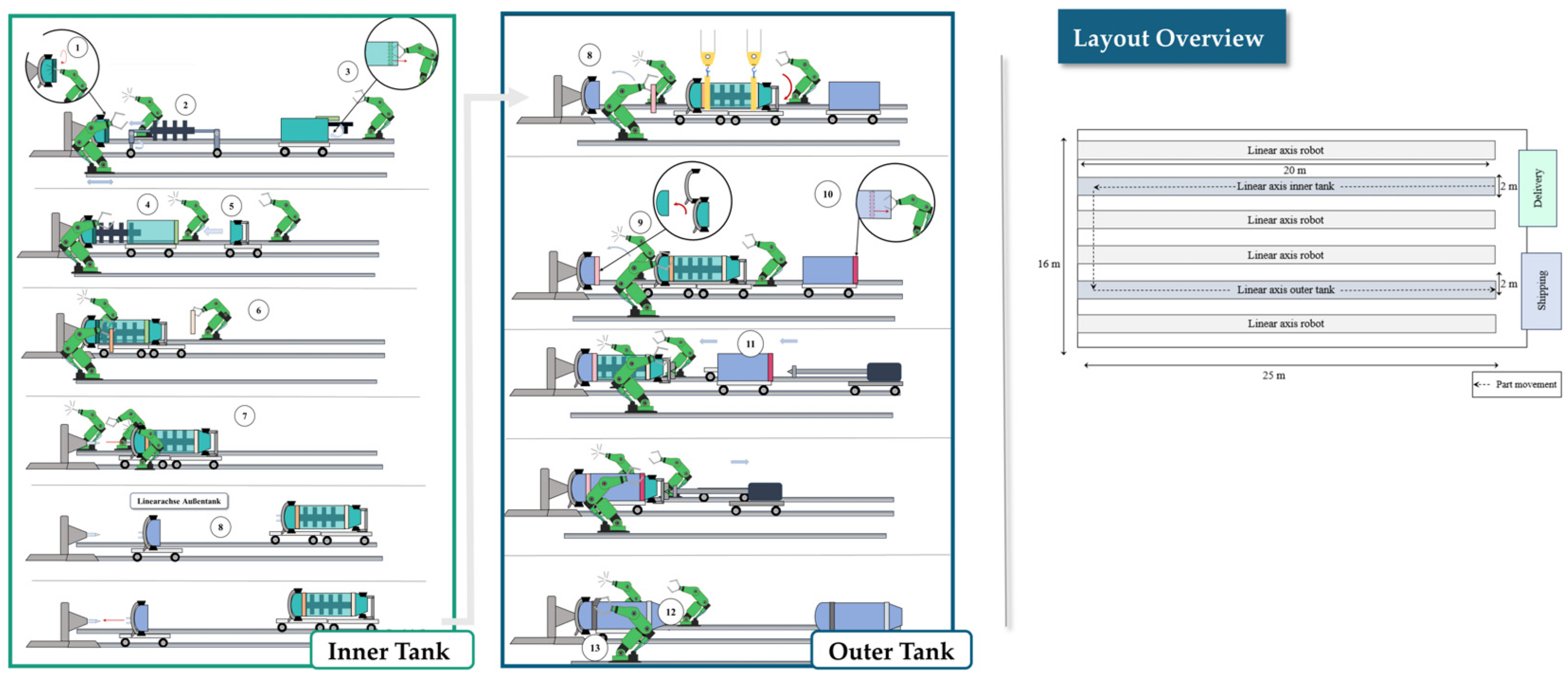
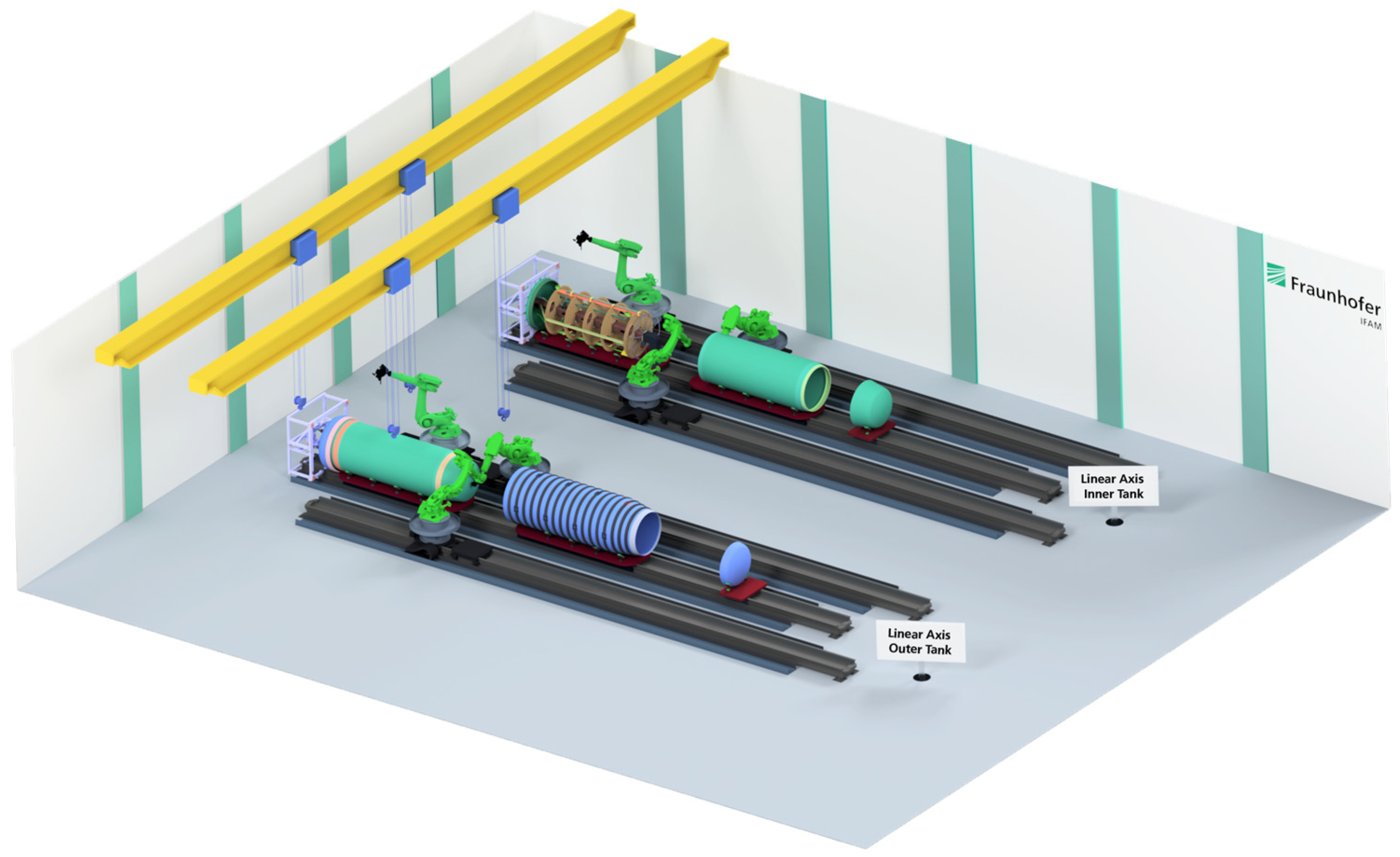
The first concept utilizes two parallel linear axes: one for the inner tank and one for the outer tank. Components and robots move along these axes, allowing for parallel processing and a sequential, robust build-up (see Figure 2).

3.1.2. Concept 2: Flexible Cell (FC)

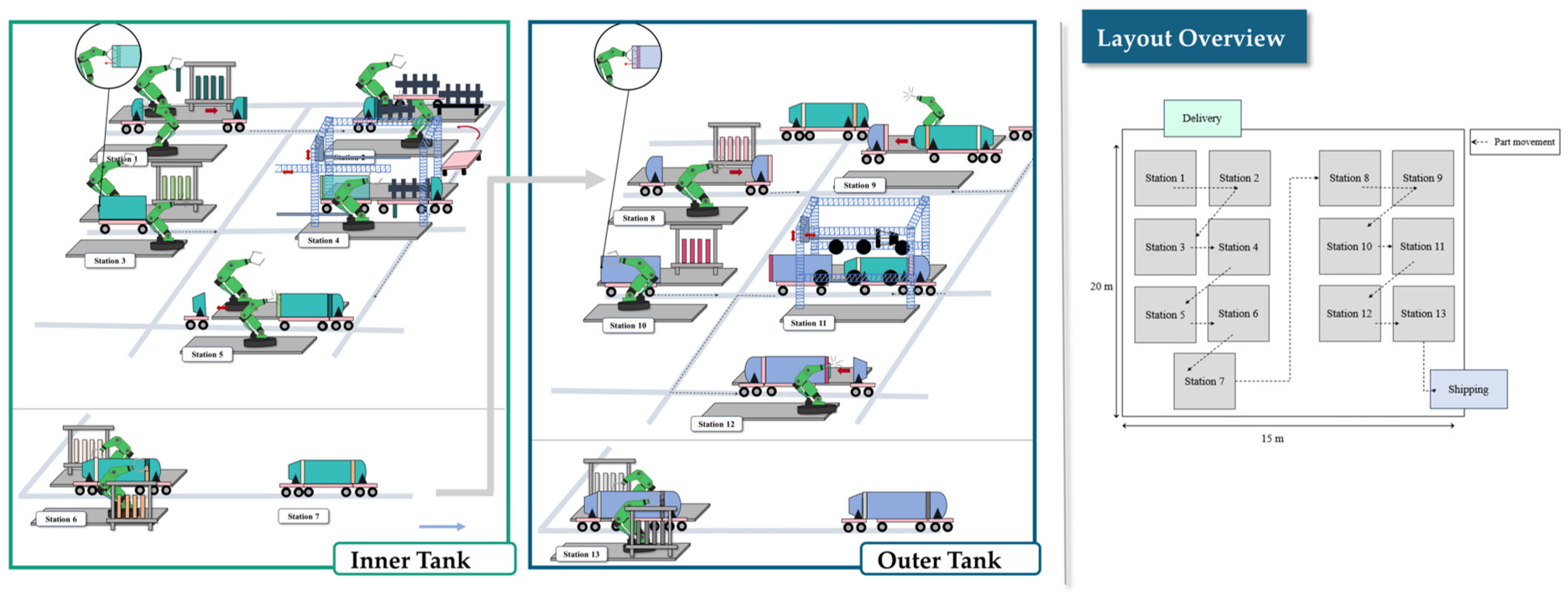
Concept 2 is designed as a “Clean-Shop-Floor” solution utilizing a station-based layout. Automated Guided Vehicles (AGVs) transport components between discrete assembly stations, offering high modularity (see Figure 3).

3.1.3. Concept 3: Hydrogen Assembly Cell (HAC)

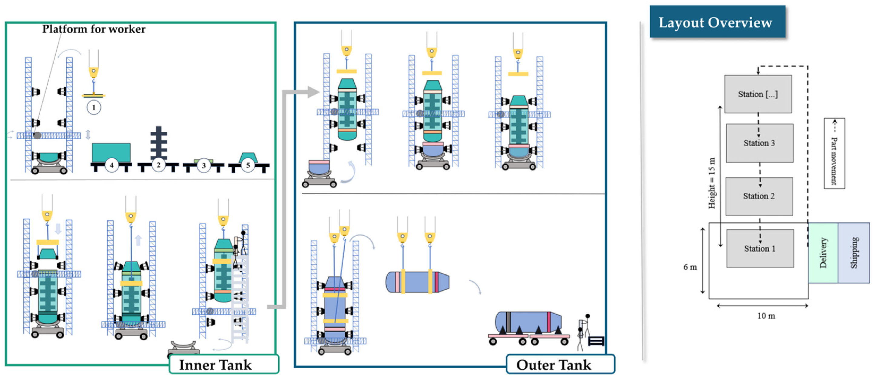
This concept employs a vertical assembly process similar to rocket manufacturing. Components are lifted by cranes and lowered into a central assembly cell, optimizing vertical space usage (see Figure 4).

3.1.4. Concept 4: Robot Line with Cooperative Component Assembly (RCC)

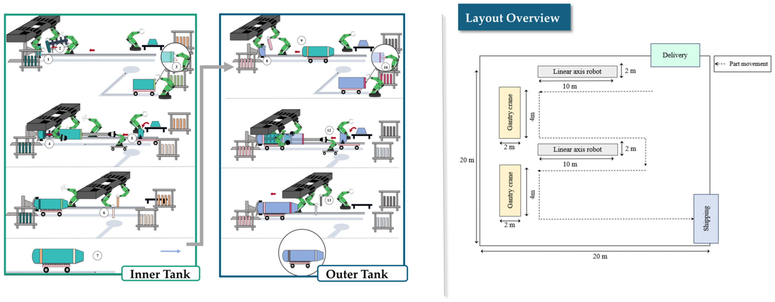
Concept 4 combines elements of Concept 1 and Concept 2, employing linear-axes robots alongside gantry cranes and AGVs to enable a highly automated and cooperative workflow (see Figure 5).

3.2. Evaluation

To select the most suitable concept for industrial application, the four variants were subjected to a rigorous, weighted evaluation. This assessment was conducted in collaboration with partners from Fraunhofer IFAM (Research), FFT (plant manufacturer), and Airbus (Aircraft Manufacturer).
Eleven criteria derived from the assembly requirements formed the basis of the evaluation. The weighting factors, initially determined through a pairwise comparison matrix reflecting industrial needs [20], were subsequently refined in consultation with FFT, Fraunhofer IFAM, and Airbus. Table 2 summarizes the final criteria and their respective weights.
The four different concepts were evaluated using a weighted scoring model. To determine the final ranking, the weighted mean for each concept was derived by multiplying the individual performance scores by their respective importance weightings, which were established through stakeholder consensus. The criteria were initially evaluated independently by experts from Airbus, Fraunhofer IFAM, and FFT. Subsequently, these individual assessments were harmonized in close consultation between all stakeholders to ensure that the weighting reflects both industrial requirements and technical feasibility.
This collaborative approach ensures high practical reliability of the results, as the chosen parameters represent a consolidated expert consensus from the fields of aerospace manufacturing, automation, and materials science. This systematic assessment resulted in a ranking of the four assembly configurations (see Table 3), with the Modular Mounting System on Linear Axes (MML) emerging as the superior solution by achieving the highest aggregate score and demonstrating the strongest alignment with the defined technical requirements.
Concept 1 (MML) (see Figure 6) was selected as the favored concept as it represents the best compromise between meeting all process requirements, ensuring high process robustness, and maintaining low investment and development costs. The use of dual linear axes enables the parallelization of process steps (e.g., assembling inner and outer tanks simultaneously), which is crucial for reducing overall throughput time.
The remaining concepts exhibited significant limitations. Concept 4 (RCC) demonstrated high flexibility but was disadvantaged by elevated investment costs and increased system complexity resulting from the integration of multiple kinematic subsystems. Concept 2 (FC) also provided considerable flexibility; however, it was prone to potential AGV instability during precise joining operations and required substantial initial capital expenditure. Concept 3 (HAC) received the lowest evaluation, as its vertical assembly, while spatially efficient, introduced critical ergonomic challenges associated with working at heights, heightened safety risks, and increased operational costs due to extensive crane utilization.

4. Conclusions

This paper has detailed a systematic approach to developing a modular assembly concept for large-volume cryogenic CFRP hydrogen tanks. By analyzing requirements, defining a joining sequence, and developing four distinct concepts (MML, FC, HAC, and RCC), a comprehensive evaluation was performed with the Modular Mounting System on Linear Axes (MML) identified as the most promising solution due to its robustness, scalability, and cost efficiency. Future work includes further refinement of the selected MML concept, empirical validation, and experimental evaluation. Additional efforts will focus on developing automated solutions for adhesive application and surface pre-treatment, as well as enhancing tolerance management to meet cryogenic precision requirements.
By addressing these challenges, this research contributes to the industrialization of hydrogen-based propulsion technologies and supports the transition toward sustainable air transport.

Author Contributions

K.G. Conceptualization, methodology, investigation, writing—original draft preparation; B.D. and S.K. review and editing; supervision. All authors have read and agreed to the published version of the manuscript.

Funding

This research received no external funding.

Institutional Review Board Statement

Not applicable.

Informed Consent Statement

Not applicable.

Data Availability Statement

The data presented in this study are available on request from the corresponding author due to privacy and/or legal restrictions.

Conflicts of Interest

The authors declare no conflicts of interest.

Abbreviations

The following abbreviations are used in this manuscript:
AGVAutomated Guided Vehicle
CFRPCarbon Fiber Reinforced Plastics
CO2Carbon Dioxide
FCFlexible Cell
GH2Gaseous Hydrogen
HACHydrogen Assembly Cell
MMLModular Mounting System on Linear Axes
MLIMulti-Layer Insulation
LH2Liquid Hydrogen
RCCRobot Line with Cooperative Component Assembly
VDIVerein Deutscher Ingenieure (Association of German Engineers)

References

  1. FCH2 JU; Clean Sky 2. Hydrogen-Powered Aviation: A Fact-Based Study of Hydrogen Technology, Economics, and Climate Impact by 2050; Publications Office of the European Union: Luxembourg, 2020. [Google Scholar]
  2. Tiwari, S.; Pekris, M.J.; Doherty, J.J. A review of liquid hydrogen aircraft and propulsion technologies. Int. J. Hydrogen Energy 2024, 57, 1174–1196. [Google Scholar] [CrossRef]
  3. European Commission. Directorate General for Research and Innovation. In Fly the Green Deal: Europe’s Vision for Sustainable Aviation; Publications Office: Luxembourg, 2022. [Google Scholar]
  4. Lei, H.; Khandelwal, B. Hydrogen fuel for aviation. In Alternative Aviation Fuels; Elsevier: Amsterdam, The Netherlands, 2023; pp. 237–270. [Google Scholar]
  5. Nojoumi, H.; Dincer, I.; Naterer, G. Greenhouse gas emissions assessment of hydrogen and kerosene-fueled aircraft propulsion. Int. J. Hydrogen Energy 2009, 34, 1363–1369. [Google Scholar] [CrossRef]
  6. Proesmans, P.; Vos, R. Hydrogen, medium-range airplane design optimization for minimal global warming impact. CEAS Aeronaut. J. 2024, 15, 781–806. [Google Scholar] [CrossRef]
  7. Stautner, E.W.; Haran, K.S.; Ansell, P.J.; Minas, C. Aircraft Cryogenics, 1st ed.; Springer International Publishing: Cham, Switzerland, 2024. [Google Scholar]
  8. Prewitz, M.; Schwärzer, J.; Bardenhagen, A. Potential analysis of hydrogen storage systems in aircraft design. Int. J. Hydrogen Energy 2023, 48, 25538–25548. [Google Scholar] [CrossRef]
  9. Khandelwal, B.; Karakurt, A.; Sekaran, P.R.; Sethi, V.; Singh, R. Hydrogen powered aircraft: The future of air transport. Prog. Aerosp. Sci. 2013, 60, 45–59. [Google Scholar] [CrossRef]
  10. Züttel, A. Hydrogen storage methods. Naturwissenschaften 2004, 91, 157–172. [Google Scholar] [CrossRef] [PubMed]
  11. Huete, J.; Pilidis, P. Parametric study on tank integration for hydrogen civil aviation propulsion. Int. J. Hydrogen Energy 2021, 46, 37049–37062. [Google Scholar] [CrossRef]
  12. Colpan, C.O.; Kovač, A. (Eds.) Fuel Cell and Hydrogen Technologies in Aviation, 1st ed.; Springer: Cham, Switzerland, 2022. [Google Scholar]
  13. Stolten, D.; Emonts, B. (Eds.) Hydrogen Science and Engineering: Materials, Processes, Systems and Technology, 1st ed.; Wiley-VCH: Weinheim, Germany, 2016. [Google Scholar]
  14. Burschyk, T.; Cabac, Y.; Silberhorn, D.; Boden, B.; Nagel, B. Liquid hydrogen storage design trades for a short-range aircraft concept. CEAS Aeronaut. J. 2023, 14, 879–893. [Google Scholar] [CrossRef]
  15. Xu, W.; Li, Q.; Huang, M. Design and analysis of liquid hydrogen storage tank for high-altitude long-endurance remotely-operated aircraft. Int. J. Hydrogen Energy 2015, 40, 16578–16586. [Google Scholar] [CrossRef]
  16. Alves, M.P.; Gul, W.; Cimini Junior, C.A.; Ha, S.K. A Review on Industrial Perspectives and Challenges on Material, Manufacturing, Design and Development of Compressed Hydrogen Storage Tanks for the Transportation Sector. Energies 2022, 15, 5152. [Google Scholar] [CrossRef]
  17. Liu, N.; Ma, B.; Liu, F.; Huang, W.; Xu, B.; Qu, L.; Yang, Y. Progress in research on composite cryogenic propellant tank for large aerospace vehicles. Compos. Part A Appl. Sci. Manuf. 2021, 143, 106297. [Google Scholar] [CrossRef]
  18. Aygin, E. Advanced Manufacturing: A Key Enabler for Zero-Carbon Emission Commercial Flight; SAE Technical Paper; SAE International: Warrendale, PA, USA, 2022. [Google Scholar]
  19. Pahl, G.; Beitz, W.; Feldhusen, J.; Grote, K.-H. Konstruktionslehre: Grundlagen erfolgreicher Produktentwicklung—Methoden und Anwendung, 7th ed.; Springer: Berlin/Heidelberg, Germany, 2007. [Google Scholar]
  20. Ehrlenspiel, K.; Meerkamm, H. Integrierte Produktentwicklung: Denkabläufe, Methodeneinsatz, Zusammenarbeit, 6th ed.; Hanser: München, Germany, 2017. [Google Scholar]
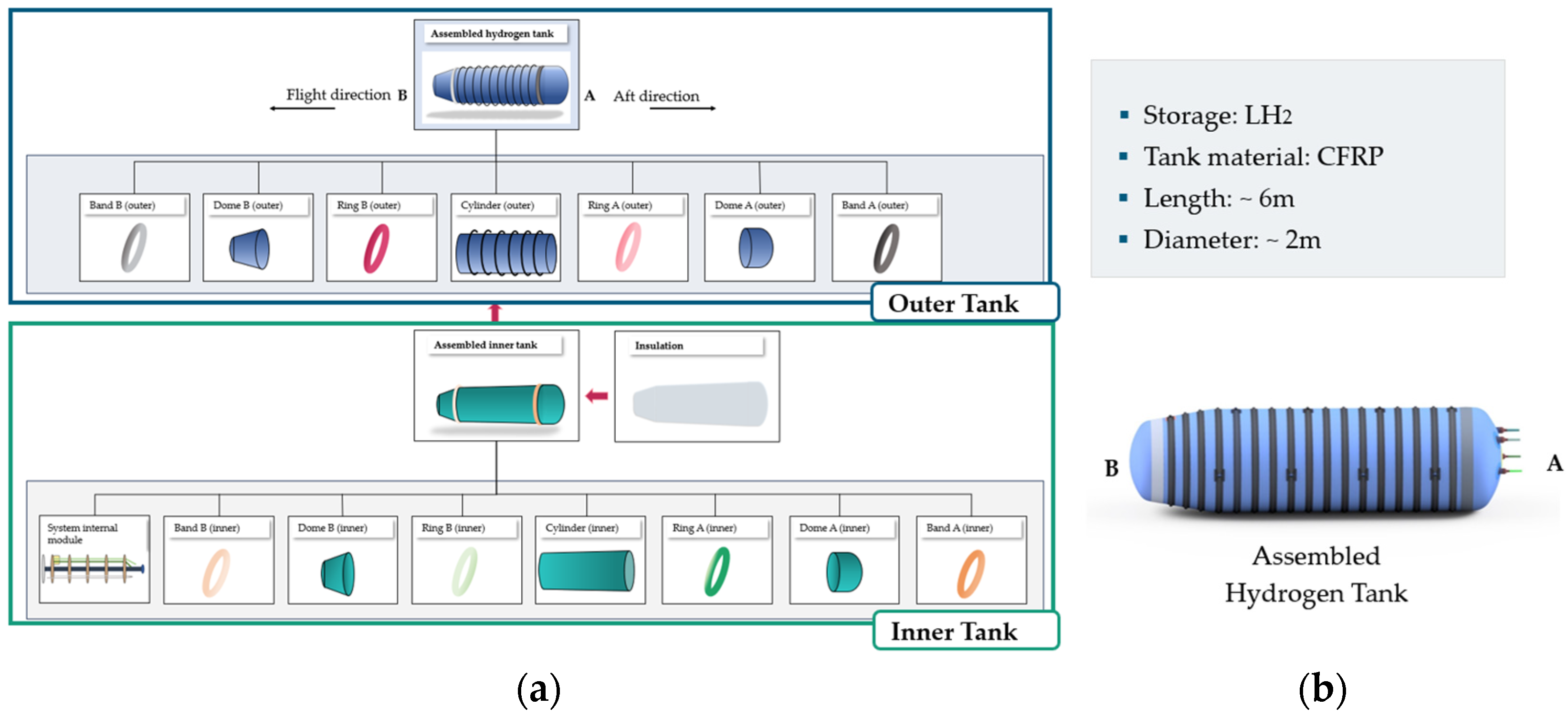
Figure 1. (a) CFRP Hydrogen Tank Components, (b) Technical Specifications of the CFRP Hydrogen Tank, with Side B oriented in the flight direction and Side A oriented in the aft direction.
Engproc 133 00179 g001
Figure 2. CFRP Hydrogen Tank Assembly—Concept 1.
Engproc 133 00179 g002
Figure 3. CFRP Hydrogen Tank Assembly—Concept 2.
Engproc 133 00179 g003
Figure 4. CFRP Hydrogen Tank Assembly—Concept 3.
Engproc 133 00179 g004
Figure 5. CFRP Hydrogen Tank Assembly—Concept 4.
Engproc 133 00179 g005
Figure 6. CAD visualization of the best rated Concept 1 (MML).
Engproc 133 00179 g006
Table 1. Morphological box—CFRP hydrogen tank assembly.
Principle of Operation 1Principle of Operation 2Principle of Operation 3Principle of Operation 4Principle of Operation 5
TransferLinear axis (C1)Overhead crane (C3)AGV (C2)Combination of AGV & crane
Fixation (in station)Positioner (Cup & Cones) (C1, C4)Magnetic gripperMechanical fastenersRobot + suction gripper (C2, C3)Clamping fixtures (C3)
ManipulationParallel robot (C2, C3)Serial axes (C2)Serial robot (C1, C4)Actuator (C1)
Mating processLinear axis (C1)AGV (C2)Serial robotCrane (C3)Hybrid (C4)
Adhesive applicationManual (C3)Robot (C1, C2, C4)Manual & robot
Assembly directionVertical (C3)Horizontal (C1, C2, C3)Vertical & Horizontal
Table 2. Evaluation criteria and weighting factors.
No.CriteriaWeighting
1Flexibility/expandability0.3
2Fulfillment of requirements/process specifications0.8
3Low lead time0.7
4Robust process (errors/maintenance)0.8
5Floor space required0.3
6Investment costs incl. development costs0.5
7Operating costs0.5
8Material intensity for system setup (sustainability)0.3
9Ergonomics & occupational safety0.2
10Training effort for the operators0.1
11Certification effort0.2
Table 3. Weighted evaluation scores.
Concept 1 (MML)Concept 2
(FC)
Concept 3
(HAC)
Concept 4
(RCC)
16.7811.4710.3016.00
Disclaimer/Publisher’s Note: The statements, opinions and data contained in all publications are solely those of the individual author(s) and contributor(s) and not of MDPI and/or the editor(s). MDPI and/or the editor(s) disclaim responsibility for any injury to people or property resulting from any ideas, methods, instructions or products referred to in the content.