Proceeding Paper

Developing a Qualification and Testing Framework for Cold Spray Repairs in Aerospace Applications †

1
Faculty of Technology, Amsterdam University of Applied Sciences, Rhijnspoorplein 2, 1091 GC Amsterdam, The Netherlands
2
Faculty of Aerospace Engineering, Department of Aerospace Structures and Materials, Delft University of Technology, Kluyeverweg 1, 2629 HS Delft, The Netherlands
3
Netherlands Aerospace Centre (NLR), 1059 CM Amsterdam, The Netherlands
*
Author to whom correspondence should be addressed.
Presented at the 15th EASN International Conference, Madrid, Spain, 14–17 October 2025.
Eng. Proc. 2026, 133(1), 178; https://doi.org/10.3390/engproc2026133178

Published: 25 May 2026

Abstract

Cold spray is a solid-state deposition technology with great potential for coating and repair applications. This study examines the compliance of the cold spray repair process with a qualification and testing framework based on the requirements set by the European Union Aviation Safety Agency (EASA). As part of this effort, the case study of a repair of a Main Landing Gear (MLG) aluminium component is investigated to demonstrate the applicability of the proposed framework. This framework integrates mechanical and microstructural evaluations, including bond strength, hardness profiling and microstructural characterisation according to relevant ASTM and ISO standards. Experimental results from post-repair testing indicated promising performance, while ongoing testing is aligning reasonably with expected benchmarks and showing compliance with the EASA requirements.

1. Introduction

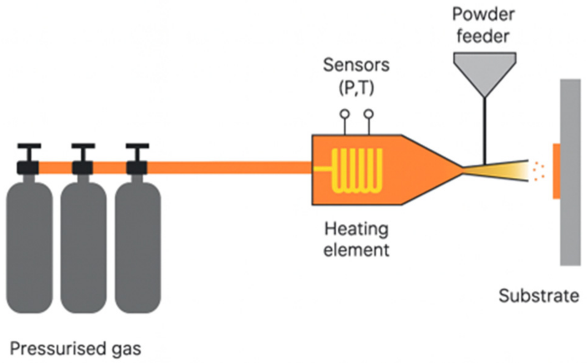
Cold spray (CS) is a solid-state deposition process which has drawn significant attention for a wide range of applications. Due to the solid-state nature of the process, which prevents thermal damage to the substrate often associated with conventional thermal spray or welding processes, the CS technology proves to have great potential as an additive repair method [1]. The working principle of cold spray is that a supersonic gas stream is used to accelerate powder particles to velocities ranging from 300 to 1500 m/s and propel them towards a substrate [2,3] as illustrated in Figure 1. Upon impact, these particles undergo plastic deformation and bond with the substrate through a combination of mechanical interlocking and metallurgical bonding mechanisms [4]. Cold spray can be applied to a wide range of materials, including aluminium, titanium, nickel, and stainless steel, making it suitable for repairing a variety of components, including worn-out turbine blades and machine parts in industries such as aerospace, automotive, and marine [1,5,6,7,8].
Previous studies demonstrated the potential of CS technology as an additive repair method and provided initial guidance for ad hoc developments, although extensive analysis and modelling were still required to address specific cases [1,2,3,4,5,6,7,8,9,10,11]. However, due to the lack of universal understanding on the CS bonding mechanism [4,12] as well as the governing process parameters and interdependencies, the current state-of-the-art contains a significant gap when it comes to the prediction of the CS repair performance and quality. The quality of a CS deposit in a repair application is determined by many different process parameters, including the particle velocity and temperature at impact, key parameters which are controlled indirectly mainly by gas pressure and temperature [13,14,15,16]. In addition, the feedstock powder characteristics, including particle size and morphology, are critical for deposit quality [15]. Moreover, the geometrical design of the repair is another important factor that governs how the load is transferred from the substrate to the cold spray deposit at the repair region and back to the substrate.
Since CS-enabled repair processes aim to restore components while ensuring compliance with regulatory standards, well-defined repair recipes and qualification frameworks are essential, particularly in highly regulated sectors such as aviation [17]. This study focuses on non-structural repairs using CS and employs an aircraft bracket as a case study to demonstrate the applicability of a qualification framework. The proposed framework integrates mechanical testing and microstructural evaluations, including bond-strength assessment, hardness profiling, and microstructural characterisation, all conducted in accordance with relevant ASTM and ISO standards. The subsequent certification process, which will be built on the qualification basis established by the present testing campaign, lies outside the scope of this study.

2. Materials and Processes

2.1. Qualification Methodology

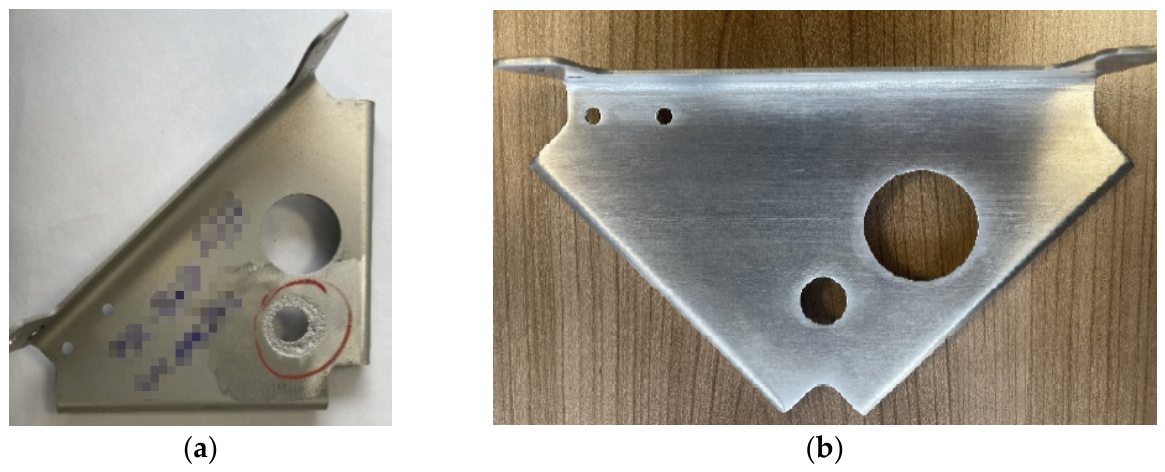
This section identifies specific requirements and compliance methods as a qualification framework for cold spray repair applications in the aviation MRO industry based on the relevant EASA regulations. In particular, the investigated use case concerns the CS repair of a typical aircraft component which is an aluminium alloy wire bundle support bracket, located in the MLG area, damaged by pitting corrosion (Figure 2).
The goal of the proposed framework is to ensure that cold spray repairs do not compromise aircraft safety or airworthiness. EASA Certification Specification for Large Aeroplanes (CS-25) [18] and Part 21—Airworthiness and Environmental Certification [19] are employed, focusing on material suitability and durability.
In particular, for the present use case, the mapping of the identified means of compliance with relevant mechanical and microstructural evaluations as outlined in ASTM/ISO standards is the following:
  • CS-25.603—bond/adhesion test in accordance with ASTM C633 [20];
  • CS-25.603—metallography and microscopic analysis in accordance with ASTM E3 [21], ASTM E2109 [22];
  • CS-25.603—hardness measurement in accordance with EN ISO 6507 [23];
  • CS-25.603, CS-25.609—environmental durability by thermal cycling in accordance with ASTM D6944 [24];
  • CS-25.603, CS25.609—corrosion testing in accordance with ASTM B117 [25] /ASTM G85 [26].

2.2. Design of Experiments

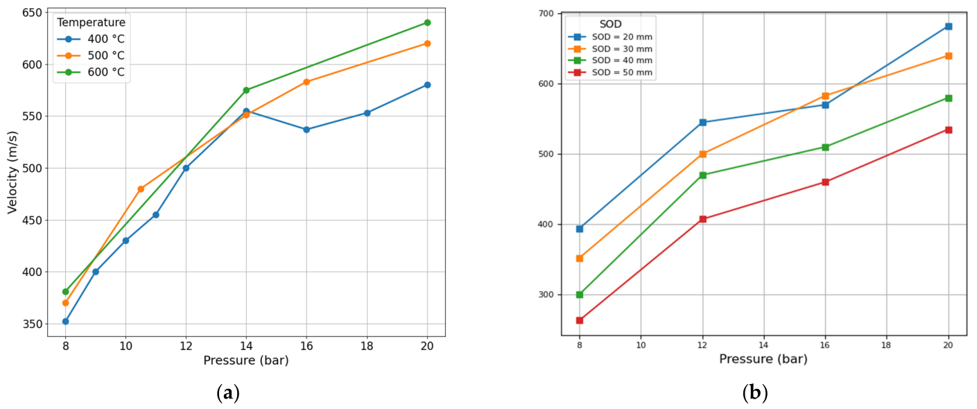
Gas temperature, pressure and stand-off distance (SOD) are among the most important parameters that determine the particle velocity at impact and, consequently, the CS repair performance and quality. A sensitivity analysis using conducted measurements with a particle image velocimetry technique indicated how the particular CS system responds to a variation in pressure, temperature and SOD, as illustrated in Figure 3. These results were used to optimise the experimental effort in terms of a reduced testing matrix. For the present testing campaign, 3 pressure levels (10, 14, 20 bar) and 2 temperature levels (400 °C, 600 °C) were chosen, resulting in a total of 6 experimental conditions. All experiments were performed with an SOD of 20 mm.

2.3. Experimental Set-Up

A series of coupons were prepared for mechanical and microstructural testing with the use of a Titomic D623 (Heerenveen, The Netherlands) CS machine by spraying Titomic LPP K-10-01 (Al/Al2O3) powder on AA 6013-T6 substrates under varying pressure (10, 14, 20 bar) and temperature (400 °C, 600 °C) conditions. As substrate material, brackets retired from in-service aircraft were used. The brackets were treated by grit blasting and surface cleaning with isopropyl alcohol before spraying as per MIL-STD-3021.

2.3.1. Bond Strength Test

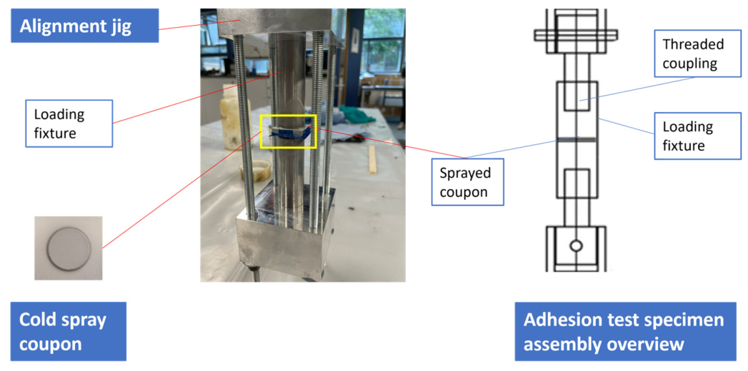
The bond strength was evaluated through the adhesion strength pull-test method according to ASTM C633. Standard circular deposits with a 25 mm diameter were prepared with the use of spraying masks on the brackets. The test specimens were manufactured by cutting a square section around the sprayed area out of the bracket and then glueing the coupons to two identical cylindrical loading fixtures with the use of the epoxy HTKUltra Bond 100 (Hamburg, Germany). An in-house developed jig was used to ensure alignment during the bonding, as illustrated in Figure 4.
The bonding strength was then measured by pull-off tests using a 200-kN tensile load machine, STEP Lab EA200 (Treviso, Italy) at the crosshead speed of 0.02 mm/sec. Before testing the CS coupons, the bonding agent was tested on unsprayed test specimens, and it was observed that the epoxy failed at 75 MPa.

2.3.2. Metallography and Microscopic Analysis

The samples for microstructural observations were cut from the brackets with a SiC cutting wheel. The samples were then mounted in an epoxy resin. Automated planar grinding was used. The samples were ground in steps with increasingly fine grit, up to 4000, and then polished with a 1 µm abrasive slurry in preparation for microscopy.
The following aspects were analysed using optical microscopy in accordance with ASTM E3, ASTM E2109:
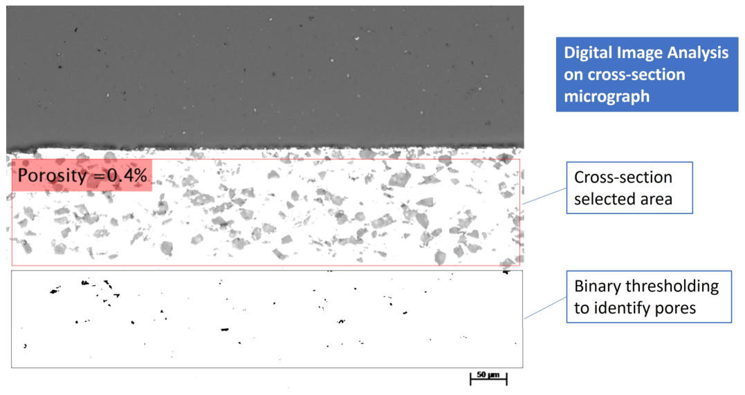
  • Porosity, by digital image analysis in MATLAB R2024a (Mathworks, Natick, MA, USA) (binary thresholding to identify pores) on images from optical microscopy.
  • Adhesion of the coating and coating defects and any other irregularities such as voids, inclusions, etc.

2.3.3. Hardness Measurements

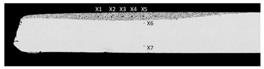
Microhardness measurements were performed after the microscopic imaging. The measurement of hardness was carried out in accordance with EN ISO 6507. A loading time of 10 to 15 s was applied. The locations of the 7 hardness measurements per cross-section and the sequence of numbering from the coating side (locations X1–X5) to the substrate (locations X6–X7) are shown in Figure 5.

3. Results and Discussion

3.1. Bond Strength Results

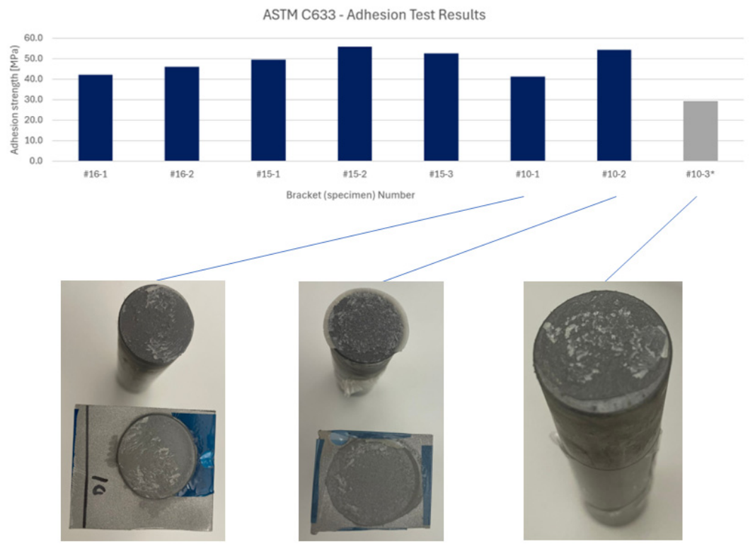
The bond strength test yielded stresses at failure, varying from 34 to 54 MPa, averaging 47 MPa, which is above the average value reported in the literature [27,28]. The failure surfaces from adhesion tests were examined to determine the failure mode. It was found that all the test specimens (with the exception of specimen #10-3, which failed due to a manufacturing defect during the application of the adhesive epoxy) consistently failed adhesively at the epoxy layer (see some examples in Figure 6). The latter implies that the adhesion strength of the CS layer is higher than the stresses recorded at failure and validates the CS bond strength as sufficient for the investigated repair.

3.2. Microscopic Analysis Results

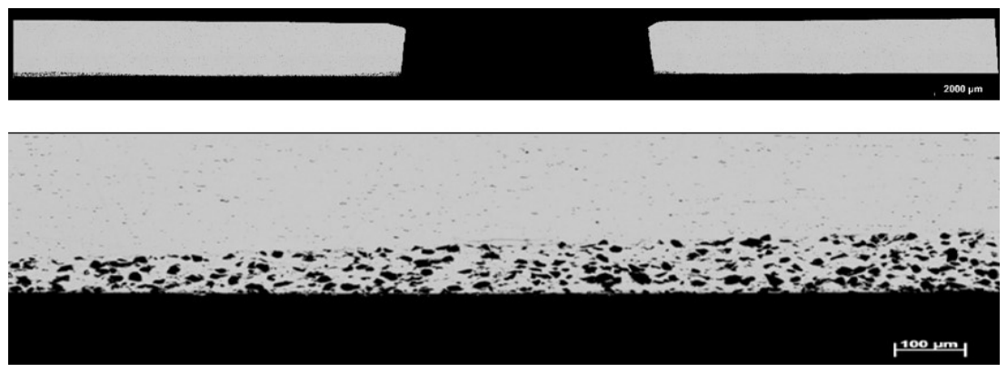
All the inspections performed on the cross-sections indicate that a CS coating was successfully deposited at the areas to be repaired. The CS coatings follow the contours of the substrate material and no significant coating defects such as cracks, delamination, or inclusions were found. Figure 7 shows cross-section 13-1 in which a flat surface and thickness restoration were obtained. For this cross section only 0.6% of the total linear CS bond line length was affected by a single minor crack (probably due to poor removal of the pitted area of the previous step and not induced by the CS), i.e., 99.4% of the bond line was free of defects.
Moreover, preliminary results from cross-sections cut from two different brackets yielded a porosity rating up to 0.4% (as illustrated in Figure 8), which is lower or comparable to porosity ratings for relevant Al/Al2O3 CS coatings on various substrates [28,29,30].

3.3. Hardness Measurements Results

Preliminary results indicate that the CS deposit hardness is approximately 70–80 kg/mm2 (HV0.1) according to EN ISO 6507. The detailed results from hardness measurements on cross-section 3-1 are denoted in Table 1, and the corresponding indentations are shown in Figure 5. The CS deposit microhardness results are reasonably comparable to observed data for relevant Al/Al2O3 CS coatings on various substrates [28,31,32].

4. Ongoing and Future Work

Ongoing testing is focusing on the environmental durability of the CS repaired components. Preliminary thermal cycling testing has been conducted in an environmental chamber according to ASTM D6944. Two repaired brackets underwent 30 cycles between 55 °C/−28 °C without detection of any damage in the repaired surface during NDT inspection. Moreover, planned corrosion testing aims to investigate the corrosion resistance of the CS repairs. Samples will be subjected to a neutral salt spray test according to ASTM B117, simulating environmental exposure to moisture and salt. Regular inspections and metallographic cross-sections are planned to assess corrosion damage. Future work includes additional measurements during mechanical and microstructural evaluations to investigate the effect of the process conditions on the resulting CS performance.

5. Conclusions

This study evaluates the compliance of cold spray repairs for non-structural aircraft parts within an EASA-aligned qualification and testing framework, using bond-strength tests, hardness profiling, and microstructural characterisation following relevant ASTM and ISO standards. Experimental results from post-repair testing of a typical aircraft component indicated promising performance while ongoing testing is aligning reasonably with expected benchmarks and showing compliance with the EASA requirements. Further insights on the effect of the process conditions on the resulting CS performance are part of future work.

Author Contributions

Conceptualization, K.S., S.K., B.B. and J.-A.P.; methodology, K.S., S.K., B.B., L.A. and J.-A.P.; software, S.K., and B.B.; validation, K.S. and J.-A.P.; formal analysis, K.S. and J.-A.P.; investigation, K.S., S.K., B.B. and L.A.; writing—original draft preparation, K.S. and M.A.; writing—review and editing, K.S., M.A., S.K., B.B., L.A. and J.-A.P.; project administration, K.S. and J.-A.P. All authors have read and agreed to the published version of the manuscript.

Funding

The authors wish to acknowledge funding from the Netherlands Enterprise Agency (RVO; Dutch: Rijksdienst voor Ondernemend Nederland) Subsidy Scheme R&D Mobility Sectors (RDM) within the BrightSky project, grant number MOB21010.

Institutional Review Board Statement

Not applicable.

Informed Consent Statement

Not applicable.

Data Availability Statement

The data presented in this study were generated and analysed by AUAS, Epcor, NLR and TU Delft in the context of the BrightSky project. These datasets are not readily available at this moment because they are part of ongoing research within the BrightSky project. Further enquiries can be directed to the corresponding author.

Acknowledgments

The authors gratefully acknowledge the support and participation of Mary Patrick, Peter van der Veldt and EPCOR BV in the experimental testing, which was essential for the completion of this work.

Conflicts of Interest

The authors declare no conflicts of interest. The funders had no role in the design of the study; in the collection, analyses, or interpretation of data; in the writing of the manuscript; or in the decision to publish the results.

References

  1. Tan, K.; Markovych, S.; Hu, W.; Shorinov, O.; Wang, Y. Review of Manufacturing and Repair of Aircraft and Engine Parts Based on Cold Spraying Technology and Additive Manufacturing Technology. Aerosp. Tech. Technol. 2020, 3, 53–70. [Google Scholar] [CrossRef]
  2. Papyrin, A.; Kosarev, V.; Klinkov, S.; Alkimov, A.; Fomin, V. Chapter 5—Current Status of the Cold Spray Process. In Cold Spray Technology; Papyrin, A., Kosarev, V., Klinkov, S., Alkimov, A., Fomin, V., Eds.; Elsevier: Oxford, UK, 2007; pp. 248–323. [Google Scholar]
  3. Assadi, H.; Gärtner, F.; Stoltenhoff, T.; Kreye, H. Bonding Mechanism in Cold Gas Spraying. Acta Mater. 2003, 51, 4379–4394. [Google Scholar] [CrossRef]
  4. Hussain, T.; McCartney, D.G.; Shipway, P.H.; Zhang, D. Bonding Mechanisms in Cold Spraying: The Contributions of Metallurgical and Mechanical Components. J. Therm. Spray Technol. 2009, 18, 364–379. [Google Scholar] [CrossRef]
  5. Champagne, V.; Helfritch, D. The Unique Abilities of Cold Spray Deposition. Int. Mater. Rev. 2016, 61, 437–455. [Google Scholar] [CrossRef]
  6. Astarita, A.; Coticelli, F.; Prisco, U. Repairing of an Engine Block through the Cold Gas Dynamic Spray Technology. Mater. Res. 2016, 19, 1226–1231. [Google Scholar] [CrossRef]
  7. Singh, H.; Sidhu, T.S.; Kalsi, S.B.S. Cold Spray Technology: Future of Coating Deposition Processes. Frattura ed Integrita Strutturale. Gruppo Ital. Frat. 2012, 6, 69–84. [Google Scholar] [CrossRef]
  8. Vaz, R.; Garfias, A.; Albaladejo, V.; Sánchez Molino, J.; Cano, I.G. A Review of Advances in Cold Spray Additive Manufacturing. Coatings 2023, 13, 267. [Google Scholar] [CrossRef]
  9. Granata, M.; Gautier di Confiengo, G.; Bellucci, F. High-Pressure Cold Spray Coatings for Aircraft Brakes Application. Metals 2022, 12, 1558. [Google Scholar] [CrossRef]
  10. Jones, R.; Kovarik, O.; Bagherifard, S.; Cizek, J.; Lang, J. Damage Tolerance Assessment of AM 304L and Cold Spray Fabricated 316L Steels and Its Implications for Attritable Aircraft. Eng. Fract. Mech. 2021, 254, 107916. [Google Scholar] [CrossRef]
  11. Yu, T.; Chen, M.; Wu, Z. Experimental and Numerical Study of Deposition Mechanisms for Cold Spray Additive Manufacturing Process. Chin. J. Aeronaut. 2022, 35, 276–290. [Google Scholar] [CrossRef]
  12. Kundu, S.; Stamoulis, K. Qualitative Evaluation of Failure Mechanisms of Aluminium 6061-T6 Cold Spray Repairs. Eng. Fail Anal. 2025, 175, 109581. [Google Scholar] [CrossRef]
  13. Sample, C.M.; Champagne, V.K.; Nardi, A.T.; Lados, D.A. Factors Governing Static Properties and Fatigue, Fatigue Crack Growth, and Fracture Mechanisms in Cold Spray Alloys and Coatings/Repairs: A Review. Addit. Manuf. 2020, 36, 101371. [Google Scholar] [CrossRef]
  14. Schmidt, T.; Gärtner, F.; Assadi, H.; Kreye, H. Development of a Generalized Parameter Window for Cold Spray Deposition. Acta Mater. 2006, 54, 729–742. [Google Scholar] [CrossRef]
  15. Silvello, A.; Cavaliere, P.D.; Albaladejo, V.; Martos, A.; Dosta, S.; Cano, I.G. Powder Properties and Processing Conditions Affecting Cold Spray Deposition. Coatings 2020, 10, 91. [Google Scholar] [CrossRef]
  16. Nourian, A.; Schwartz, T.; Boese, S.; Müftü, S. Effects of Process Parameters on Cold Spray Deposition of Al-6061 Alloy. J. Therm. Spray Technol. 2022, 31, 2517–2536. [Google Scholar] [CrossRef]
  17. Stamoulis, K. Innovations in the Aviation MRO: Adaptive, Digital, and Sustainable Tools for Smarter Engineering and Maintenance; Eburon Academic Publishers: Amsterdam, The Netherlands, 2022. [Google Scholar]
  18. EASA. Certification Specifications and Acceptable Means of Compliance for Large Aeroplanes (CS-25) Amendment 28. 2025. Available online: https://www.easa.europa.eu/en/document-library/certification-specifications/cs-25-amendment-28 (accessed on 24 November 2025).
  19. EASA. Part-21. In Easy Access Rules for Airworthiness and Environmental Certification; Regulation (EU) No 748/2012; EASA: Cologne, Germany, 2022. [Google Scholar]
  20. ASTM C633-24; Standard Test Method for Adhesion or Cohesion Strength of Thermal Spray Coatings. ASTM International: West Conshohocken, PA, USA, 2024.
  21. ASTM E3-26; Standard Guide for Preparation of Metallographic Specimens. ASTM International: West Conshohocken, PA, USA, 2026.
  22. ASTM E2109-01; Standard Test Methods for Determining Area Percentage Porosity in Thermal Sprayed Coatings. ASTM International: West Conshohocken, PA, USA, 2021.
  23. EN ISO 6507-1:2023; Metallic materials—Vickers hardness test—Part 1: Test method. International Organization for Standardization: Geneva, Switzerland, 2023.
  24. ASTM D6944-15(2025); Standard Practice for Determining the Resistance of Cured Coatings to Thermal Cycling. ASTM International: West Conshohocken, PA, USA, 2025.
  25. ASTM B117-26; Standard Practice for Operating Salt Spray (Fog) Apparatus. ASTM International: West Conshohocken, PA, USA, 2026.
  26. ASTM G85-19; Standard Practice for Modified Salt Spray (Fog) Testing. ASTM International: West Conshohocken, PA, USA, 2019.
  27. Lee, H.Y.; Jung, S.H.; Lee, S.Y.; You, Y.H.; Ko, K.H. Correlation between Al2O3 Particles and Interface of Al–Al2O3 Coatings by Cold Spray. Appl. Surf. Sci. 2005, 252, 1891–1898. [Google Scholar] [CrossRef]
  28. Spencer, K.; Fabijanic, D.M.; Zhang, M.X. The Use of Al–Al2O3 Cold Spray Coatings to Improve the Surface Properties of Magnesium Alloys. Surf. Coat. Technol. 2009, 204, 336–344. [Google Scholar] [CrossRef]
  29. Weiller, S.; Francesco, D.; François, W.; Alain, T.; Jeandin, M.; Cédric, G. Influence of Porosity on Ultra-High Vacuum Gas-Tightness in Cold-Sprayed Aluminum Coatings. Transp. Porous Media 2022, 144, 339–366. [Google Scholar] [CrossRef]
  30. Maizeray, A.; Marcos, G.; Cappella, A.; Planche, M.P.; Liao, H.; Henrion, G.; Czerwiec, T.; Martin, J. Effects of Dispersed α-Al2O3 Particles into a Cold-Sprayed Aluminium Coating on Its Subsequent Oxidation by the PEO Process. Surf. Coat. Technol. 2024, 482, 130713. [Google Scholar] [CrossRef]
  31. Bai, X.; Tang, J.; Gong, J.; Lü, X. Corrosion Performance of Al–Al2O3 Cold Sprayed Coatings on Mild Carbon Steel Pipe under Thermal Insulation. Chin. J. Chem. Eng. 2017, 25, 533–539. [Google Scholar] [CrossRef]
  32. Jiang, W.; Shen, X.; Wang, Z.; Liu, Y.; Zhang, X.; Wang, E.; Zhang, J. Effect of Al2O3 on Microstructure and Corrosion Characteristics of Al/Al2O3 Composite Coatings Prepared by Cold Spraying. Metals 2024, 14, 179. [Google Scholar] [CrossRef]
Figure 1. Illustration of the cold spray deposition process.
Engproc 133 00178 g001
Figure 2. Images of the aircraft MLG bracket (AA 6013-T6), which has been employed as a use case: (a) bracket damaged by pitting corrosion around the indicated hole; (b) bracket repaired with CS.
Engproc 133 00178 g002
Figure 3. Particle velocity response of the system for (a) varying pressure and temperature (SOD at 30 mm) and (b) varying SOD, pressure and constant temperature (400 °C).
Engproc 133 00178 g003
Figure 4. CS repair test specimen preparation according to ASTM C633.
Engproc 133 00178 g004
Figure 5. Locations of microhardness testing on cross-section 3-1 of bracket #3 (locations X1–X5 in coating side, locations X6–X7 in substrate).
Engproc 133 00178 g005
Figure 6. Results of bond strength test according to ASTM C633. Coupon #10-3* failed at a lower load due to poor application of the adhesive epoxy.
Engproc 133 00178 g006
Figure 7. Microscopic analysis general observations and CS bond line quality.
Engproc 133 00178 g007
Figure 8. Porosity rating results according to ASTM E3/ASTM E2109.
Engproc 133 00178 g008
Table 1. Hardness values of CS deposit and substrate of bracket #3, cross-section 3-1.
Mass (g) 100Deposit Substrate
LocationX1X2X3X4X5X6X7
HV K g m m 2 72.379.174.881.176.9139.2144.3
Dim. y (μm)51.849.751.647.149.136.536.0
Dim. x (μm)49.547.148.048.549.136.535.7
HV Average K g m m 2 76.8 141.7
Disclaimer/Publisher’s Note: The statements, opinions and data contained in all publications are solely those of the individual author(s) and contributor(s) and not of MDPI and/or the editor(s). MDPI and/or the editor(s) disclaim responsibility for any injury to people or property resulting from any ideas, methods, instructions or products referred to in the content.