Proceeding Paper

Design, Analysis and Optimisation of a Vacuum-Insulated Composite Conformal LH2 Tank †
1
Royal Netherlands Aerospace Centre, Voorsterweg 31, 8316 PR Marknesse, The Netherlands
2
Applied Research & Technology, Collins Aerospace, Penrose Business Centre, 4th Floor, Penrose Wharf, T23 XN53 Cork, Ireland
3
Crompton Technology Group, Safran, Chalker Way, Banbury OX16 4XD, UK
4
NOVOTECH Aerospace Advanced Technology, Via G. Pascoli 7, 80026 Casoria, Italy
*
Author to whom correspondence should be addressed.
Presented at the 15th EASN International Conference, Madrid, Spain, 14–17 October 2025.
Eng. Proc. 2026, 133(1), 165; https://doi.org/10.3390/engproc2026133165
Published: 19 May 2026

Abstract

Hydrogen-propelled aircraft can enable net-zero CO2 emissions in aviation, which is the goal of the International Civil Aviation Organization (ICAO) for 2050. One drawback of onboard hydrogen storage in aircraft is the necessity for relatively large, pressurised storage volumes. To maximise H2 volumetric efficiency, the COmposite COnformal LIquid H2 Tank (COCOLIH2T) project attempts to design, build and test a vacuum-insulated liner-less cryogenic conformal thermoplastic composite tank with conditioning subsystems for safe operation. The tank must be compatible with the design envelope in the empennage, specifically towards the aft of the pressure bulkhead of an ATR 72-like aircraft. The tank design, analysis, optimisation and demonstrator manufacturing are presented in this paper.

1. Introduction

The aviation industry is seeking innovative solutions to reduce its environmental impact and improve efficiency. At present, the industry is making efforts to further reduce its environmental impact towards net-zero CO2 emissions by exploring alternative energy and propulsion systems. One such alternative is hydrogen, either by converting the energy to electricity or via combustion.
One major difficulty of introducing a novel energy source into highly optimised structures like aircraft is efficient integration. In the COCOLIH2T project, the partners investigate how to efficiently integrate liquid hydrogen storage into an existing ATR 72-like aircraft. A major difficulty with hydrogen is that it either requires storage at very low cryogenic temperatures (20 K if liquid) or at a very high pressure, or a combination of both. Therefore, a Liquid Hydrogen (LH2) tank requires a structure that provides exceptionally good thermal insulation and can sustain a pressure load of several times the atmospheric pressure, both of which are requirements that a kerosene fuelled aircraft do not require.
In this work, a double-walled vacuum-insulated low-pressure tank concept has been developed. The vacuum-insulated double wall offers superior insulation compared to other solutions such as foam or fibre insulation. In order to keep the inner and outer tank separate, a tank spacer design concept has been developed and manufactured. To sustain minor crash loads while keeping thermal conductivity at a minimum, the spacer structure has been designed with a long thermal path and the necessary strength and stiffness. COCOLIH2T project involves the design and construction of two composite demonstrator tanks. Demonstrator 1 is intended to be subjected to mechanical (pressurisation) and thermal loading with liquid nitrogen without the installation of subsystems. Demonstrator 2 (not covered in this paper) will be installed with subsystems and health monitoring sensors and then filled with LH2 to demonstrate fuelling, refuelling, gauging, sloshing and mechanical load resistance to achieve Technology Readiness Level (TRL) 4. Insights gained from the first demonstrator will inform the design of second demonstrator.

2. Materials and Methods

2.1. Tank Main Requirements

At the beginning of the COCOLIH2T project, High Level Requirements and Objectives were defined and reported in an HLRO document that served as the initial specifications for the design of the tank. This document specifies requirements from an aircraft-level perspective and assumes a Certification Specification 25 (CS-25, [1]) hybrid aircraft with fuel cells, with the LH2 tank located in the aft tail cone of the aircraft.
The key performance indicators (KPIs) of the project are a liquid hydrogen capacity of 57 kg, a dormancy longer than 24 h, a boil-off of less than 2% per day after dormancy, a tank gravimetric index (GI, mass of H2 stored divided by tank mass with H2) of 25% and a TRL of 4 at the end of the project.
An important geometric requirement is that the tank, with its subsystems and piping, should fit in the available design envelope in the aft section of the ATR 72 aircraft, which has a volume of 1293 litres behind the pressure bulkhead. However, stringent dormancy and venting requirements alongside the integration of subsystems and piping necessitated an expanded design envelope. Consequently, the pressure bulkhead is relocated as forward as possible to provide the required design envelope.
The normal ground and flight limit loads that the tank should be able to resist are −12g down, +6 gup, +/−1.5g lateral, +1.5g forward and −1g aft, where a safety factor of 1.5 should be applied to the flight loads. These acceleration loads are in combination with an inner tank maximum working pressure of 4 bar(a) and atmospheric pressure working on the outside skin of the outer tank. No leakage, rupture or permanent distortion should occur under these loads; fitting attachments are allowed to distort permanently.
The tank should also be able to resist minor crash-landing loads, which are considered ultimate loads, with an inner tank maximum working pressure of 4 bar(a) and atmospheric pressure working on the outside skin of the outer tank. The acceleration loads considered are −6g down, +3g up, +/−3g lateral, +9g forward and −1.5g aft, which are referred to as ultimate emergency landing loads per CS-25 [1]. No rupture and no leakage are allowed, while permanent deformation of fitting attachments is allowed.
The proof pressure of the inner tank is 6 bar(a) without leakage and permanent deformation. The burst pressure of the inner tank is 8 bar(a), where we adapt a no-leakage requirement. The maximum working pressure of the inner tank is 4 bar(a) with atmospheric pressure on the outside of the outer tank with no leakage or permanent distortion allowed.

2.2. Tank Material Selection

2.2.1. Inner Tank

The material for the inner tank of Demonstrator 1 is T800/LM PAEK with a carbon fibre volume fraction (FVF) of 60%. The effective elastic constants used in the conceptual and detailed design phase, assuming a quasi-isotropic (QI) layup and neglecting temperature dependency, are shown in Table 1.

2.2.2. Outer Tank

For the outer tank of Demonstrator 1, the thermoset material T800/TC380 2x2 twill fabric was chosen. The effective elastic constants for a QI layup, neglecting temperature dependency, are given in Table 2.

2.2.3. Tank Spacers

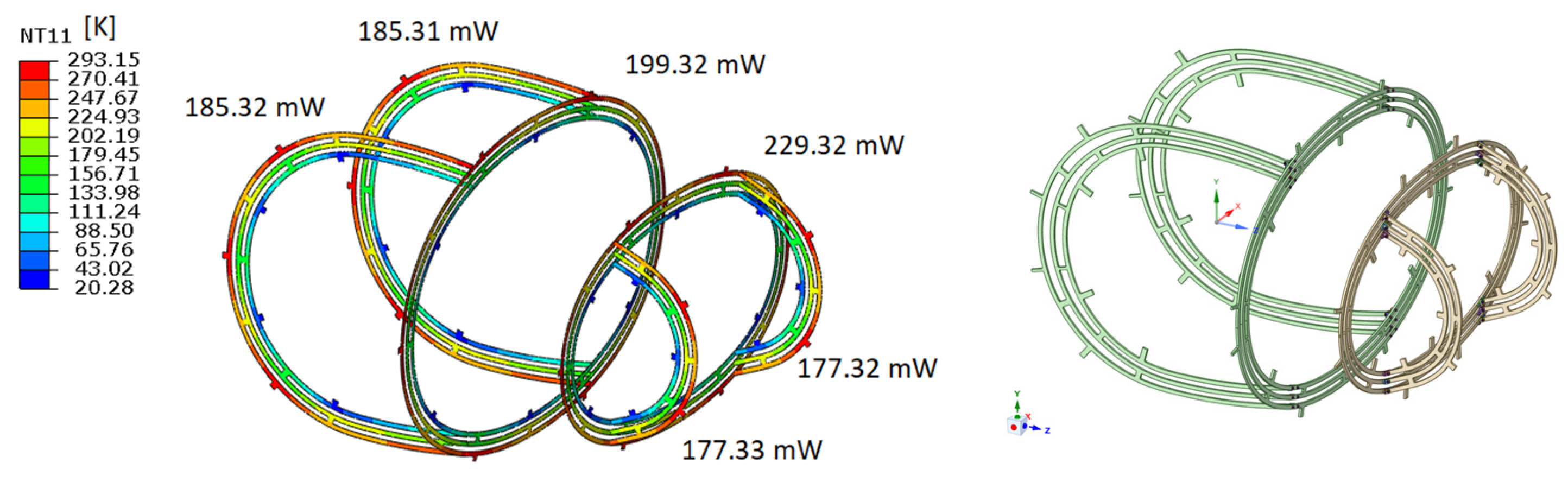
For the tank spacers shown in the right-hand images of Figure 1 a cryogenic-grade woven glass fibre-reinforced epoxy material (G-10CR) was chosen. This material has a relatively low and strongly decreasing thermal conductivity between room temperature and 20 K. The temperature-dependent thermal conductivity, specific heat and coefficients of thermal expansion (CTEs) of this material can be found on the NIST website [2]. This material is also used for liquefied natural gas (LNG) pipe supports and space applications and can considerably minimise heat leak through conduction when well designed. The in-plane thermal conductivities of this material are equal and higher than the thermal conductivity in the normal direction. The in-plane CTEs are smaller than those in the normal direction. For the thermo-mechanical tank analysis in the detailed design phase the temperature-dependent elastic properties shown in Table 3 were used.
The axial-oriented and circumferential spacers will be connected by angle brackets made from PEEK CM CT200 and metal screws. The angle brackets with screws, considered as lug connections, were analytically checked for strength using lug strength methods from reference [3].

2.2.4. Interface Plates

The inner tank is manufactured by Automated Fibre Placement (AFP) on a closed, collapsible mandrel which is secured to the rotary system via a central tube. This mandrel configuration led to two polar openings at the forward and aft ends of the inner tank, see right image in Figure 1. Additionally, the requirement to locate the fuel level sensor, pressure relief valve and burst disc piping at the highest point in the tank geometry necessitated another hole. Interface plates are designed to host these attachments while robustly sealing the interfaces.
The inner tank interface plates are made from Invar (Fe-36Ni), which has a very low CTE, to prevent large thermal stresses with the composite tank. The interface plates are bolted to the tank. In those regions, the tank is thickened to enable bolting with helicoils onto the composite. The outer tank interface plate, which is exposed to ambient temperature, is made from stainless steel 316.

2.2.5. Multi-Layer Insulation

In order to minimise the radiation from the relatively warm outer tank to the cold inner tank, the inner tank and 2 gaseous lines and 1 liquid hydrogen line in the vacuum space of the tank will be wrapped with COOLCAT 2 NW Multi-Layer Insulation (MLI) material from Beyond Gravity (Zurich, Switzerland) [4]. This is a layered material consisting of 10 layers of polyester foil, which are double-sided aluminized perforated foils, interleaved with 10 layers of non-woven polyester spacer material. The MLI has a nominal compressed thickness of 1.4 mm per 10 layers, and a minimum gap thickness of 3 mm per 10 layers is recommended for installation. This MLI material was tested in a vacuum chamber at NLR with MLI layers wrapped around a frame with a heater box inside to determine the temperature distribution between the layers due to radiation heat transfer. A pack of 4 layers (10 foils + 10 spacers per layer) will be applied around the inner tank. Furthermore, 1 pack will be applied around the tank spacers going through a slot of the tank spacers, because the outer strips of the tank spacers are still relatively warm. Finally, the LH2 line and the pressure relief and burst disc line located in the vacuum space of the tank will be wrapped with 1 pack.

2.3. Material Characterisation Tests

Coupons were manufactured from the thermoplastic material T800/LM PAEK by AFP followed by Vacuum Bag Only (VBO) oven consolidation. An annealing treatment was carried out to investigate if thermally induced stresses could be reduced. Also, a material quality assessment was performed to check for voids and cracks. Cryogenic tensile tests were performed at NLR with different layups to determine strength and stiffness at 20 K. Some tests were interrupted for microscopic inspection on microcracks. Permeation tests were conducted using helium at various temperatures, revealing promising permeability behaviour that assures the suitability of the material for the inner tank. Furthermore, pull-out tests were performed with helicoils inserted into the thermoplastic composite material to replicate the interface plate attachment to the inner tank with bolts. The results of all these material tests are not listed here, because that would be too extensive. They do show that low-level tests were performed to de-risk manufacturing and testing of the complete tank.

2.4. Conceptual Tank Design

In the absence of established material properties for T800/LM-PAEK at cryogenic temperatures (20 K), the conceptual tank design utilised conservative allowables. This approach was adopted to mitigate risk while a separate characterisation campaign was conducted in parallel. Thermal stresses occur when the composite laminate is cooled down to 20 K. These thermal stresses knock down a large percentage of the matrix strength. In the absence of material data at 20 K, the maximum allowable laminate stress before matrix microcracking was estimated to be ~93 MPa. This specific value represents a critical threshold, i.e., any further reduction would make thermoplastic composite less favourable for cryogenic applications, despite the advantages of its high specific strength. The ~93 MPa estimation is based on an additional margin on matrix stress of at least 15 MPa at ply level due to mechanical loading. Furthermore, the ~93 MPa allowable is also depending on the ratio between laminate stiffness for a QI layup and stiffness in the transverse matrix direction at ply level.
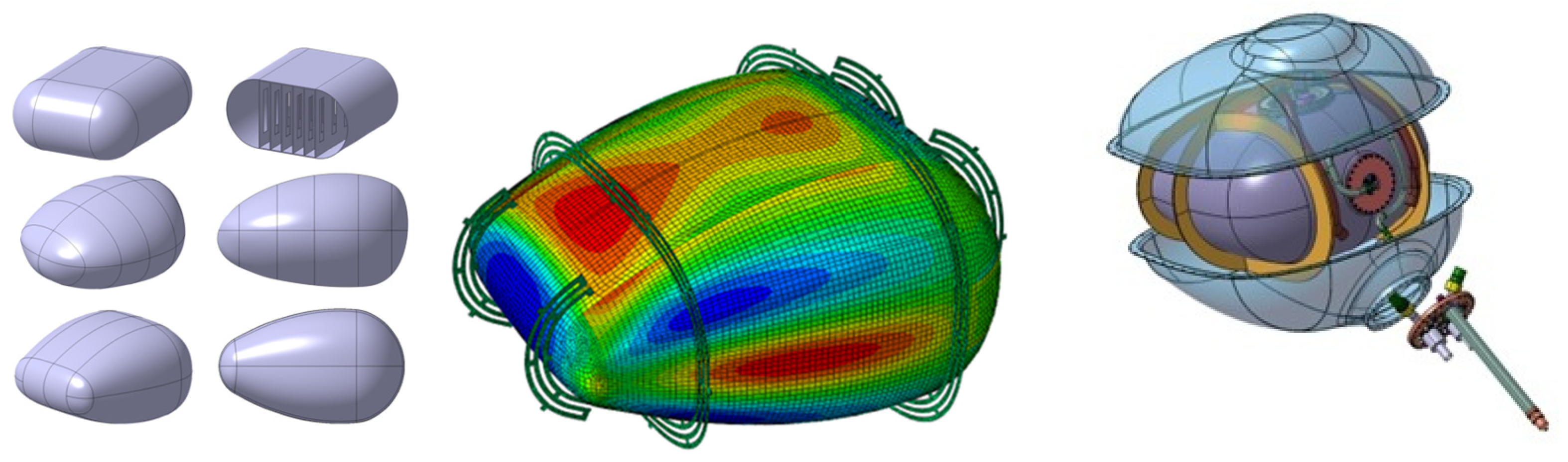
In the conceptual shape design study, different inner tank shapes were investigated and analysed, from braced box-shaped designs to egg-shaped designs, and designs based on super ellipses, also known as the Lamé curves; see images on the left-hand side of Figure 1. The bracing elements in the box-shaped concept are used to reduce the bending stress, since structures that are not exactly circular tend to become circular under internal pressure. This concept was not chosen because it was considered complex and expensive to manufacture. The second design concept that was investigated was an egg-shaped design. For this concept, only a single mould is required and it has inherent bending stiffness due to the doubly curved skin all around. The third design is very similar to the egg-shaped design. It still has a doubly curved skin all around, but now the shape is based on super ellipses. The advantages of this concept are a scientifically rigorous approach to defining the geometry; the curvature of the skins (and thus the stress level and the degree of conformability) can be directly tuned via the n-value of the Lamé curve; it is relatively easy to manufacture and only a single mould is required. The inner tank design based on super ellipses was considered most promising. A patchwork design with different thicknesses at different areas of the tank was chosen to reduce overall weight of the tank. The outer tank was assigned a uniform thickness and, initially, a uniform distance of ~100 mm was used between the inner and outer tank. The tank spacers were initially modelled as 6 separate tank spacers with 2 circumferential spacers and 4 spacers oriented in axial/flight direction.

2.5. Inner Tank Design Optimisation

The conceptual inner tank design based on super ellipses was optimised in two steps by Collins Aerospace (Charlotte, NC, USA) [5]. In the first step, the geometry of the inner tank was optimised by shape optimisation, and in the second step, the composite laminate was optimised with the objective to reduce structural mass. In the shape optimisation constraints such as design envelope, which was finally extended to 3.78 m3 by moving the pressure bulkhead forward as much as possible, the max. inner tank volume (1.1 m3) and allowable matrix stress (<16 MPa) were taken into account, with minimum weight as the objective. For the laminate optimisation, the tank body between the domes of the tank was optimised for layup and thickness using a patchwork design with different thickness zones. The domes were approximated as QI laminates and were also optimised for thickness. The laminate optimisation was performed with an in-house bi-level optimisation framework coupled with the Abaqus FEM model of the inner tank, taking into account the polar bosses and the front and rear interface plates [6].

2.6. Integrated Tank Design

In the detailed design phase, a thermo-mechanical analysis of the tank was carried out in Abaqus (version 2023) with the inner tank, outer tank and 6 connected tank spacers. The geometry of the tank spacers was optimised to minimise conductive heat loss by creating a long thermal path and reducing the spacer thickness. The objective was to keep the thermal conductive heat loss below 1.2 W. The thermo-mechanical analysis was carried out with an outer tank thickness of 4.8 mm, a patchwork design for the inner tank with thicknesses in the range of 5.68–11.36 mm and a tank spacer thickness of 7.925 mm. The uniform spacing between the inner and outer tank in this analysis was 100 mm and the legs of the tank spacers were assumed to be connected to the inner and outer tank walls. A temperature of 20 K was prescribed for the inner tank and 293 K for the outer tank. The outer tank flange was restrained at 4 points where it attaches to the test frame by fitting attachments. The normal ground and flight loads, and minor crash-landing loads were prescribed as acceleration loads alongside inertial load from 57 kg of LH2, applied as a surface traction load. The maximum working pressure in the inner tank is 4 bar and the maximum pressure that can work on the outside of the outer tank is 1.09 bar.

2.7. Tank Manufacturing

The inner tank of Demonstrator 1 was manufactured by AFP at NOVOTECH (Naples, Napoli) using in situ AFP consolidation and periodic VBO oven consolidation. The outer tank halves for Demonstrator 1 were manufactured by NOVOTECH in a mould with VBO oven consolidation. The tank spacers were water jet-cut from purchased G-10CR plate material by NLR, and the legs will be cut to the correct length and curvature before installation in the tank. The angle brackets for the tank spacers were made by CNC machining.

3. Results

3.1. Conceptual Tank Design Results

3.1.1. Inner and Outer Tank Results

In the conceptual design phase, different patchwork designs of the inner tank were analysed for all normal ground and flight loads and minor crash-landing loads. For the inner tank patchwork design with skin thicknesses in the range of 7.95–19.88 mm, the maximum principal stress due to the burst load case of 8 bar is ~95 MPa (see tank areas with red colour in Figure 1), which is right at the assumed limit of matrix microcracking. For this tank design, buckling of the outer tank skin with a uniform thickness of 6.82 mm is predicted to occur at 1.53 times the external overpressure, at the top skin near the narrow end.

3.1.2. Tank Spacer Results

In the +9g forward crash load case, the axial spacers take up most of the load and to a lesser degree load is taken up by the circumferential spacers. The stress in the tank spacers due to the +9g forward crash load case is low, and buckling of the tank spacers was not encountered for a spacer thickness of 12.7 mm.

3.2. Integrated Tank Design Results

3.2.1. Tank Spacer Thermo-Mechanical Analysis Results

The calculated steady-state temperature distribution in the tank spacers is shown in the picture on the left in Figure 2, together with the conductive heat transfer through the axial and circumferential tank spacers. The total heat transfer by thermal conduction only is 1.15 W for a spacer thickness of 7.925 mm, which is lower than the set target of 1.2 W. Thermal radiation was not considered in this analysis. The final tank spacer design is shown on the right in Figure 2, which had to be updated due to a more aft location of the inner tank relative to the outer tank.
Considering the room temperature properties of the tank spacers, under 18g downwards load case, the smallest safety factor on the material allowable for the tank spacers is 2.58. All other safety factors are ≥3.22. Provided that the strength of the material increases at low temperatures and the FEM model does not include a corner radius, which typically leads to peak stress reduction, the actual safety factor should be more conservative than reported values.

3.2.2. Tank Buckling Analysis Results

A linear buckling analysis step was performed with the tank FEM model, including tank spacers, after a pre-load analysis step in which the inner tank maximum working pressure of 4 bar and outer tank pressure of 1.09 bar were applied together with gravity load and fuel load on the bottom of the inner tank. This resulted in a buckling load that is 3.26 times the nominal overpressure of 1.09 bar. The first buckling mode occurs again in the outer tank skin near the narrow end.

3.3. Tank Manufacturing Results

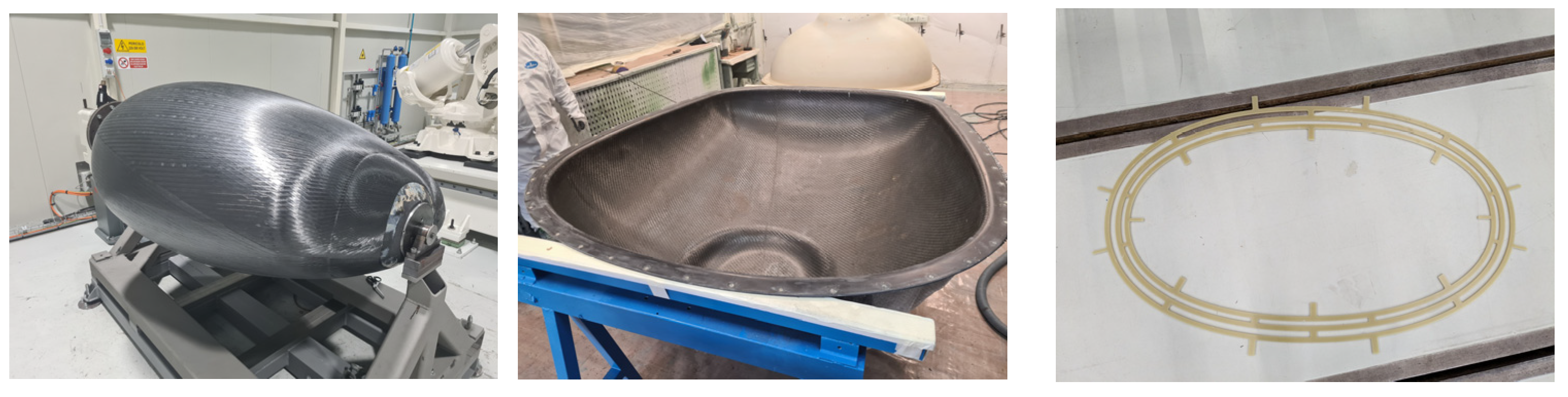
The inner tank installed on the mandrel after the AFP process is shown in the left-hand side image of Figure 3. A 1 bar(g) air pressure test of the inner tank, conducted after the mandrel was removed, revealed several leakages that will need to be resolved for the second demonstrator to be safely tested with liquid hydrogen. The top outer tank half after removal from the mould is shown in the middle picture, and a circumferential tank spacer can be seen on the right.

4. Discussion

To accommodate the top interface plate and pipework in the vacuum space, a bump on the outer tank was necessary; see the right-hand side image in Figure 1. This bump was not taken into account at the time the buckling analysis was done. Therefore, the tank buckling analysis will have to be repeated with an updated tank FEM model. Nevertheless, the impact on the buckling safety factor is expected to be minimal. Although analyses show that the tank design for Demonstrator 1 can resist all mechanical and thermal loads, manufacturing defects like nominal size deviations and other possible defects like voids and fibre waviness are not taken into account in the FEM model. The inner tank of Demonstrator 1 will be checked at a later stage for defects using non-destructive inspection, sectioning and microscopic research. Manufacturing and assembly required slight changes in the tank spacers, but the effect on the thermal conductive heat loss is expected to be small. The tank GI could be improved in the future by using composite interface plates and reducing the inner tank thickness by using a permeation barrier. The second demonstrator will employ a thermoset composite material with a permeation barrier effecting the smaller, uniform wall thickness and improve leak proofness and overcoming the difficulties during the manufacture of Demonstrator 1.

5. Conclusions

Based on the tank buckling analysis, no buckling is foreseen of the outer tank skin during operation. The analyses also show that the tank design for Demonstrator 1 is able to resist the mechanical and thermal loads if no defects are present. The predicted thermal conductive heat loss through the tank spacers is only 1.15 W. The estimated Demonstrator 1 inner tank weight with polar bosses is 91 kg. The current estimated tank GI for Demonstrator 1 is ~16%, incl. stainless steel pipes and interface plates. It must be noted that scaling up the tank capacity can lead to improved GI due to a reduced relative weight. As the tank becomes larger, the internal volume increases at a faster rate than surface area (i.e., structural mass), while the dead weight of insulation, spacers, interface plates, pipes and valves remain the same, constituting a smaller percentage of the total weight. The achieved leak tightness of the inner tank of Demonstrator 1 prevents safe testing with LH2. However, the consortium aims to enhance the leak tightness in the second demonstrator by applying lessons learnt from the manufacturing process of Demonstrator 1.

Author Contributions

Conceptualization, J.C. and P.L.; methodology, R.C., K.R., A.K.T., B.N., A.d.W. and A.t.N.; software, K.R.; validation, R.C., K.R., B.N., A.d.W. and A.t.N.; formal analysis, R.C., K.R., A.K.T., B.N., A.d.W. and A.t.N.; investigation, A.t.N. and R.U.; resources, L.L.; data curation, R.U.; writing—original draft preparation, B.N.; writing—review and editing, A.d.W.; visualisation, R.C., B.N. and L.L.; supervision, J.C. and P.L.; project administration, J.C., P.L. and R.U.; funding acquisition, J.C. All authors have read and agreed to the published version of the manuscript.

Funding

This research and APC was co-funded by EU Clean Hydrogen Partnership, grant number 101101404. The project is supported by the Clean Hydrogen Partnership and its members. Views and opinions expressed are, however, those of the authors only and do not necessarily reflect those of the European Union or Clean Hydrogen Joint Undertaking. Neither the European Union nor the granting authority can be held responsible for them.

Institutional Review Board Statement

Not applicable.

Informed Consent Statement

Not applicable.

Data Availability Statement

The original contributions presented in this study are included in the article. Further inquiries can be directed to the corresponding author.

Conflicts of Interest

Authors Karthik Ramaswamy and Jack Cullinan were employed by the company Collins Aerospace and Leonardo Lecce by NOVOTECH Aerospace Advanced Technology, whereas Amit Kumar Tripathi and Paul Liddel were affiliated by the company Safran. The remaining authors declare that the research was conducted in the absence of any commercial or financial relationships that could be construed as a potential conflict of interest.

References

  1. Certification Specifications and Acceptable Means of Compliance for Large Aeroplanes (CS-25), Amendment 27; EASA: Cologne, Germany, 2021; pp. 1–1389.
  2. NIST Cryogenic Material Properties Database. Available online: https://trc.nist.gov/cryogenics/materials/G-10%20CR%20Fiberglass%20Epoxy/G10CRFiberglassEpoxy_rev.htm (accessed on 18 November 2025).
  3. Niu, M.C.Y. Airframe Stress Analysis and Sizing, 2nd ed.; Hong Kong Conlimit Press Ltd.: Hong Kong, China, 1999; pp. 321–343. [Google Scholar]
  4. Beyond Gravity. Cryogenic Insulation Products; Product brochure; Beyond Gravity: Vienna, Austria, 2023; pp. 1–18. [Google Scholar]
  5. Ramaswamy, K.; Wehrle, E. Design and optimisation of a composite conformal liquid hydrogen tank. In Proceedings of the 27th International Conference on Composite Structures (ICCS 27), Bologna, Italy, 3–6 September 2024. [Google Scholar]
  6. Ramaswamy, K.; Liddel, P.; Noordman, B.; Creemers, R.; Di Gaetano, F.; Tripathi, A.K.; De Wit, B.; Ancierno, R.; Wehrle, E.; Lecce, L.; et al. Design, Optimisation and Manufacturing of a Composite Conformal Liquid Hydrogen Tank. In Proceedings of the Mechcomp10, Porto, Portugal, 23–25 July 2025. [Google Scholar]
Figure 1. Braced box-shaped (top left), egg-shaped (middle left) and super-ellipse-based design (bottom left); max. principal stress due to burst pressure (middle); and final tank design (right).
Engproc 133 00165 g001
Figure 2. Steady-state temperature distribution [K] in tank spacers with conductive heat transfer [mW] through tank spacers (left) and final tank spacer design with angle brackets (right).
Engproc 133 00165 g002
Figure 3. Manufacturing result of inner tank (left), top outer tank half (middle) and circumferential tank spacer (right).
Engproc 133 00165 g003
Table 1. Material properties used in this work in [MPa/-] for QI T800/LM PAEK with FVF = 60%.
E11E22E33ν12ν13ν23G12G13G23
62,22962,22910,0000.3160.280.2823,64132003200
Table 2. Material properties used in this work in [MPa/-] for T800/TC380 fabric with FVF = 55%.
E11E22E33ν12ν13ν23G12G13G23
54,43954,43979000.3150.280.2820,70528002800
Table 3. Temperature-dependent material properties used in this work in [MPa/-/K] for G-10CR.
E11E22E33ν12ν13ν23G12G13G23T
35,90029,10025,1900.210.3420.3610,35010,13010,1604
33,70027,00020,6000.190.3440.3588208590863077
28,00022,40010,7500.150.3390.34620050405050295
Disclaimer/Publisher’s Note: The statements, opinions and data contained in all publications are solely those of the individual author(s) and contributor(s) and not of MDPI and/or the editor(s). MDPI and/or the editor(s) disclaim responsibility for any injury to people or property resulting from any ideas, methods, instructions or products referred to in the content.