Proceeding Paper

Evaluation of One Engine Inoperative Scenarios for Electrified Multi-Engine Aircraft from the Certification Perspective †
German Aerospace Center (DLR), Institute of Electrified Aero Engines, Lieberoser Str. 13a, 03046 Cottbus, Germany
*
Authors to whom correspondence should be addressed.
Presented at the 15th EASN International Conference, Madrid, Spain, 14–17 October 2025.
Eng. Proc. 2026, 133(1), 139; https://doi.org/10.3390/engproc2026133139
Published: 13 May 2026

Abstract

One approach to make the aviation sector climate-compatible is to minimize greenhouse gas emissions by employing electric and hybrid electric propulsion system concepts. The introduction of novel technologies introduces novel failure modes and consequently effects of failure conditions on the aircraft. This study examines the safety of distributed electrified aircraft propulsion systems and evaluates individual failure scenarios in the context of the relevant certification requirements. A comparison of the functional architectures of legacy and Electric Hybrid Propulsion Systems (EHPSs) is conducted and the existing aircraft-level requirements, that are based on experience with conventional propulsion systems, are assessed for their applicability to the certification of novel propulsion systems. Subsequently the relevant safety items from these requirements are identified in the context of a critical loss of thrust scenario. Analysis methods are assigned to these safety items in order to prove the compliance of the novel systems with the legacy certification documentation. This results in a validation concept for EHPS at the aircraft level in the context of a critical loss of thrust. In particular, the distribution of individual subsystems and components throughout the aircraft leads to reduced isolation of the respective propulsion systems and thus potential safety-critical interactions with adjacent systems. The analysis demonstrates that the use of distributed propulsion systems increases the risk of multiple failures of redundant systems and cascading failure propagation, highlighting the need to develop targeted means of prevention and the mitigation of failure conditions for these systems.

1. Introduction

To make the aviation sector climate-compatible novel Electric Hybrid Propulsion System (EHPS) concepts are being developed. They represent a possibility to drastically reduce emissions and improve efficiency [1]. Their certification poses a considerable challenge and existing standards need to be rethought or novel standards need to be developed. The certification process in the aviation industry is a rigorous and closely regulated procedure that ensures the airworthiness of any aircraft, engine or component that is intended for use in an aircraft. For any aircraft to be certified in Europe, the process is governed by the European Union Aviation Safety Agency (EASA) [2]. The agency publishes Certification Specifications (CSs) that define the requirements and standards for initial and continued airworthiness. The primary function of the EHPS is to ”provide propulsive power”, enabling the aircraft to generate thrust and maintain flight. This function is essential for continued safe flight and landing. The detailed requirements for the propulsion systems are provided in certification documents like CS 25 and CS 23 [3,4]. However, the novel propulsion architecture and interdependence of aerodynamic control and propulsion in DEP systems require clear guidance, which the established standards are unlikely to provide. Documents like Special Condition 19 (SC 19) [5] and Means of Compliance 80 (MOC 80) [6] begin to cover certification aspects of EHPS but do not consider DEP architectures at the aircraft level. Advancements in the certification of electrified systems have been made in eVTOL and small single-engine aircraft, leading to the first type certificate for a Light Sport Aircraft (LSA), the Pipistrel Velis Electro. Highly integrated Distributed Electrified Propulsion Systems (DEPSs) have a significant influence on aircraft dynamics in flight. If a fraction of thrust generation is lost, engine, performance, and stability and control requirements need to be satisfied. Rajamani et al. assess unsolved issues in electrified aircraft certification in their research report [7]. They portray different perspectives on the certification process and highlight the relevant challenges in the certification of electrified aircraft. It is stated that the novel propulsion architecture and the interdependence of aerodynamic control and propulsion in DEPS require clear guidance, which the established standards are unlikely to adequately provide. During the NASA project X-57, several safety issues, in particular in regard to the DEP concept, have been identified [8]. Borer et al. [8] proposed a solution to manage the challenge to control a DEP aircraft like the X-57 in case of an inoperative engine. Measures herein proposed affect the certification of the operational flight manual of the respective aircraft and exceed the scope of an engine certification. Based on the state of the current research, this work assesses the applicability of legacy safety and certification requirements established in CS 25 to novel aircraft concepts that use DEPS for thrust generation. The One Engine Inoperative (OEI) scenario is used as a reference scenario for the applicability assessment. A coarse abstract functional system architecture of the aircraft and propulsion systems is used to evaluate the applicability of the certification requirements. The system model is primarily based on previous project work [9] and on the input of corresponding system and subsystem specialists. It is assessed if the potential failure modes of the EHPS leading to an OEI case are comparable to the ones exhibited by LPS.

2. Methodology

2.1. Functional System Architecture

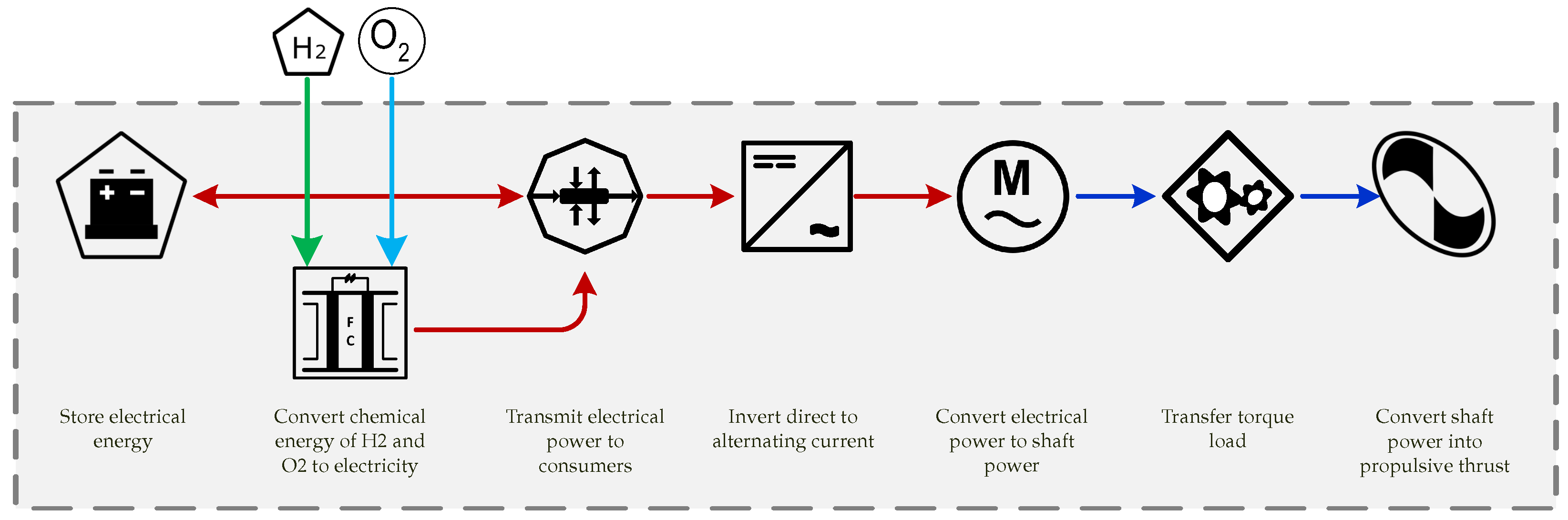
To conduct a preliminary safety assessment, a coarse functional system architecture is defined. A Functional Block Diagram (FBD) is used to describe the system architecture and its behavior. The FBD depicts the major subsystems and interfaces, with each subsystem assigned a basic function from which failure conditions and malfunctions are subsequently derived. The FBD shown in Figure 1 depicts the relevant subsystems and functions of an EHPS. It serves to establish the system boundaries, which are crucial for implementing specific safety analyses [10].

2.2. Elaboration of a Certification Approach

The relevant and valid certification specifications and according requirements are identified based on the context of this work and the previously defined system architectures. The differences in the certification of novel EHPS and LPS was already explained in [12] by the EASA. Two ways of EHPS certification approaches are described in the document. On the one hand, the aircraft approach, where “[…] the EHPS is certified as part of an aircraft” and, on the other hand, the engine approach where “[…] the EHPS is certified as an engine product—by determining those components and equipment (of the EHPS) necessary for the functioning and control […]” [12] (p. 4) of the respective engine. As the level of safety must remain stable regardless of the certification approach used, the requirements for the certification of the EHPS remain the same. The novelty is introduced in the phase of validation and the demonstration of compliance with the certification requirements in the development process as well as in the responsibilities of the continued airworthiness. A method for the validation and compliance demonstration of the certification requirements of a DEPS (consisting of several EHPS subsystems and components distributed alongside the wingspan of the aircraft and other EHPS subsystems and components located in the fuselage of the aircraft) is described in the following sections of this document, followed by a recommendation for a certification approach. When implementing the certification approach, it is necessary to identify what requirements are valid for the concerned system and to check their feasibility and validity for the developed product. When evaluating the system’s compliance with the certification requirements, two perspectives need to be considered—the proper functional performance of the system and the integration of the system into the aircraft. Settele et al. [13] describe the challenges that arise with the certification of an EHPS as well as the test and verification steps to demonstrate the compliance of subsystems and components. However verification prerequisites safety and reliability targets based on a hazard assessment and a validation towards the proper certification requirements at the aircraft and system level.

2.3. Compliance Validation

The validation of the system regarding compliance with the safety standards of the respective certification specification is based on the methodologies for safety analysis according to ARP 4761A [14]. Based on these methodologies, a strategy is developed to define the means of hazard prevention and mitigation of the severity of failure effects. As a baseline for any following safety considerations, the FHA is crucial to define the severity of functional hazard and consequently the required reliability and failure tolerance. This is the reason why the function “provide propulsive power” was initially assessed at the aircraft level, based on the safety standards of the CS 25 [3]. Therefore, every CS provides a risk classification for the respective product and the inherent functions it has to fulfill. For CS 25-categorized airplanes the severity of the effect of a failure condition is defined in AMC 25.1309 [3]. Depending on the respective classification, safety requirements are provided. The safety strategy of the certification is based on two different kinds of safety requirements: the ones that aim on preventing the occurrence of failures and errors and the ones that aim to mitigate the severity of the effects of failure conditions.

3. Results

3.1. System Definition

The definition of system boundaries, subsystems and components are crucial for the propulsion system safety assessments as well as for the development of a proper certification strategy. The propulsion system is defined by the EASA in [15] (p. 9) as “an engine used or intended to be used for aircraft propulsion”. The S1000D (8.2.5) categorizes air vehicle, engines and equipment into chapters [16] and Chapter 72—“Engine Electric”—lists all the systems and subsystems concerned with the energy transformation from alternating current into torque at the shaft.
Considering the different functionalities necessary for thrust generation, this work identifies a definition that is valid for an EHPS as well as an LPS:
The smallest isolated, self-sufficient, thrust-producing arrangement of subsystems.
Figure 1 shows the basic main functions of an exemplary all-electric EHPS architecture, the corresponding subsystems, and the system boundaries (dashed lines) proposed by the EUROCAE WG 13 [17]. Compared to an LPS, the EHPS subsystems are not necessarily located within the physical system boundaries of the engine nacelle, but they are distributed throughout the whole aircraft. This aspect is crucial for the compliance check, that is also discussed later in this chapter. The hydrogen storage subsystem is not considered part of the EHPS in hydrogen-powered aircraft, consistent with legacy propulsion architectures [17].

3.2. Certification Approach

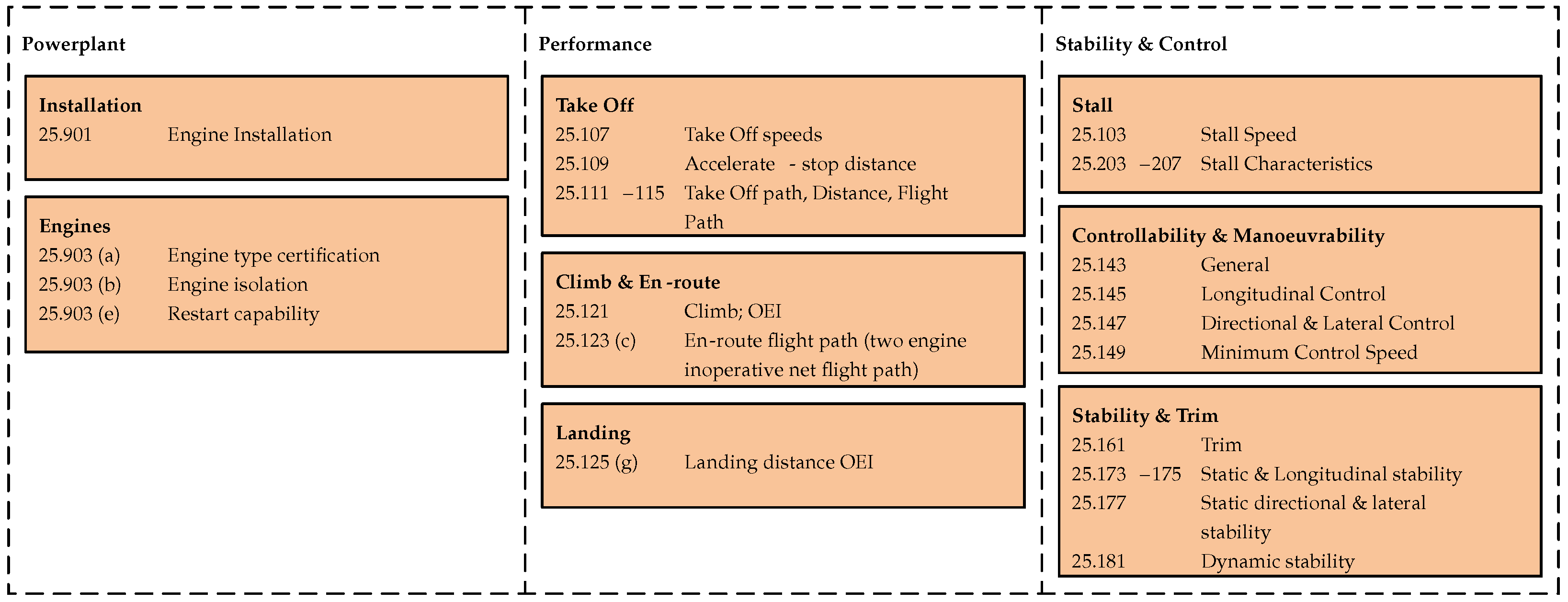
As mentioned in Section 2.2, there are different ways to certify an EHPS. A significant decision criterion is the composition of the design organizations involved in the certification of the respective subsystems, but also the integration specifications resulting from the aircraft design. According to the definition for engines by the EASA [15] (p. 9), fuel cells, propulsion batteries or the power management subsystem must be certified within the context of an entire power train. Whereas the electric propulsion motor can be certified as a separate entity as per SC E 19, with many of the certification requirements referring to the CS E [5,18]. In the case of a distributed EHPS architecture, issues arising due to the EHPS integration exceed the scope of the engine certification. This results in the need to consider an aircraft-based certification of the entire propulsion system with the SC E 19 referring to aircraft certification documents as well. Redundant compliance demonstration with certification requirements from a different CS shall be prevented; however, safety issues that originate due to the systems complexity must be addressed when assessing a safety and certification strategy. In the case of safety considerations regarding the function “provide propulsive power”, the CS 25 and CS 23 specify requirements for the prevention and mitigation of failures and their effects occurring in the propulsion system of an aircraft. Figure 2 depicts the central CS 25 paragraphs that define the design and integration requirements mitigating the OEI failure case. The requirements are generally divided into three categories: system-level power plant, aircraft-level performance, and aircraft-level stability and control.
As the engine is an aircraft system, the engine requirements (SC 19 und CS E) are cascading down from the aircraft requirements (CS 23 and CS 25). Therefore the DEHPS must also be validated against the applicable aircraft level requirements. Conversely, the existing requirements may no longer be directly applicable and alternative requirements or means of compliance must be established. The requirement 25.903(b) Engine Isolation is used to portray and explain the way of elaboration. This requirement is the basis for all further considerations that take the operational status OEI into account. The main intention of this requirement is the isolation of the respective engines and containing the effects of a failure to the single engine. Another important aspect is the fault tolerance of the whole aircraft. It has to be able to continue a safe flight and landing in case of a faulty or inoperative engine. This failure case shall also “[…] not require immediate actions by any crew member” to limit the crew workload as mentioned in [3] (CS 25.903(b)(2)). When the requirement is applied to the EHPS architecture, it becomes clear that the term engine is ambiguous. The reason for this is that requirement 25.903(b) refers to the entire propulsion architecture due to the sequential functional dependencies, as shown in Figure 1. However, the term engine could, for example, refer to the electric motor only. To account for that ambiguity, the requirement in this context is adjusted to “propulsion system isolation”, referring to the definition elaborated in Section 3.1.

3.3. Compliance Validation

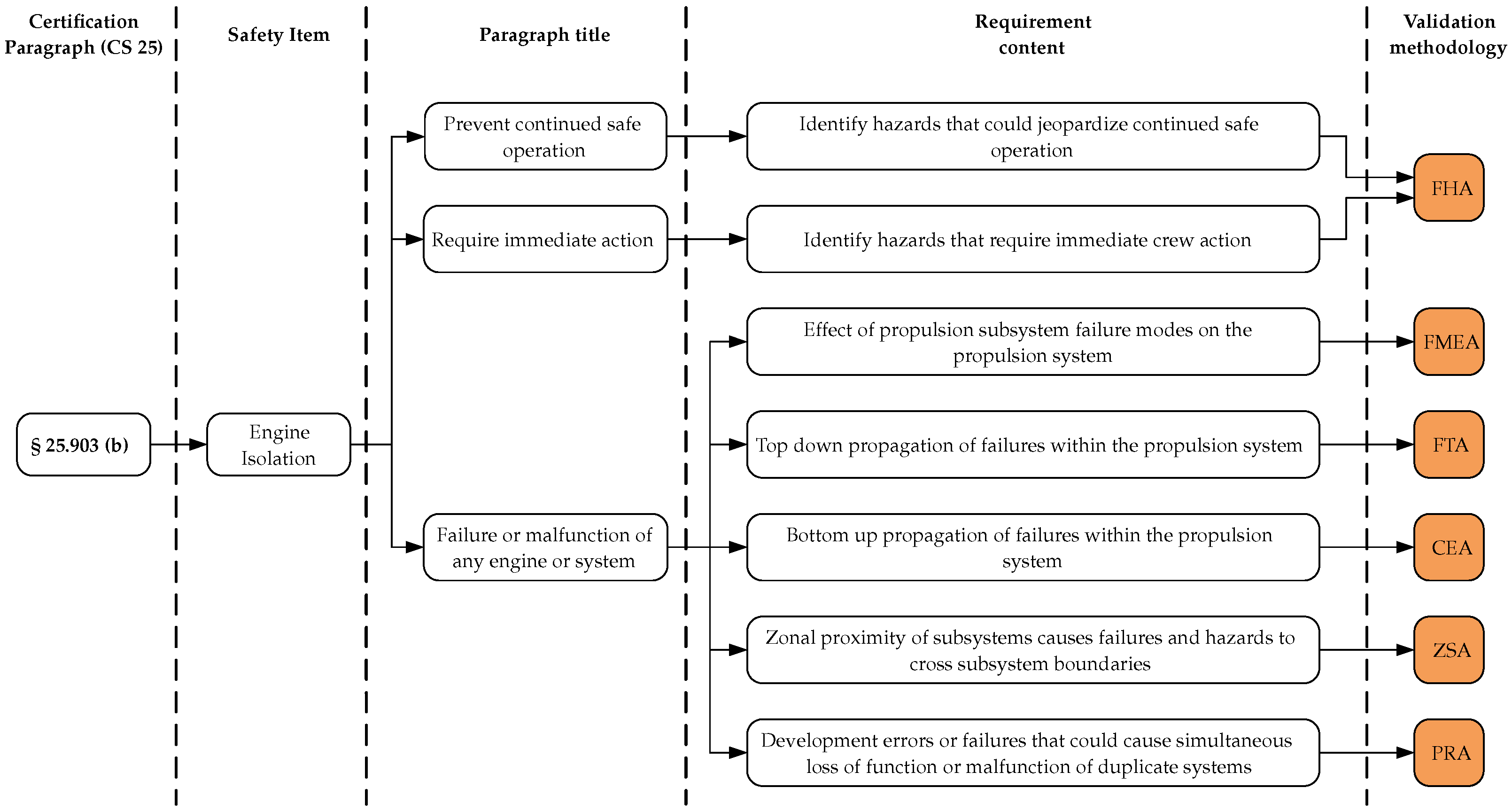
The certification requirements lead to direct safety items—like the engine isolation—compliance with which is in turn directly influenced by the design and architecture of the EHPS. The assessments, as described in ARP 4761A [14], can be assigned to the safety items and the interpretation from the perspective of the individual analysis. This relationship is visualized in Figure 3 for the example requirement 25.903(b) Engine isolation.
Assuming that the failure behavior of an EHPS will differ from that of an LPS, it is necessary to carry out an FHA at the aircraft level with a focus on propulsion system-specific failure cases. Due to the failure behavior of EHPS, in addition to the total failure of one engine (OEI), there is also the possibility of the partial failure of one or more engines. This results in a “partial loss of thrust” failure scenario. The classification of the failure condition “partial loss of thrust” is complex and has an eminent impact on subsequent design decisions at the subsystem and component level. Classification in the context partial loss of thrust has already been discussed for electrified single engine CS 23 Category 1 and 2 general aviation aircraft. This discussion was held by a Working Group of EASA, FAA and other aviation authorities [19] as well as in the proposal of the MOC to the EHPS 80 by the EASA [6], but no safety objects have been defined yet. With regard to crew workload and decision-making options in cases of failures, a fundamental investigation into the severity for the respective hazards is necessary in this context. Experience from the use of a twin-engine piston aircraft already shows that a partial loss of thrust may have a major or even hazardous classified effect on the crew and a major classified effect on the aircraft [20]. Failure modes relating to subsystems and components have to be analyzed with regard to their effect on the next higher level system, in this case the EHPS. Findings in the Failure Mode Effects Analysis (FMEA) emphasize the need for additional redundancies to mitigate the failure mode effects or prevent means to lower the probability of the occurrence of a failure event. A failure mode within a system or component can lead to several failure conditions with different effects. A thermal runaway occurring in a propulsion battery can cause both fire and toxic fume propagation, as well as a reduction or loss of thrust in dependent motor and propeller units [21]. The severity of the respective failure condition effect can be completely different. Consequently the severity of the failure mode thermal runaway in the battery compartment can be classified as catastrophic when considering the effect of fire or explosion on the occupants or aircraft, following the argumentation of Rempe et al. [22]. Whereas the effect on the aircraft as a result of the reduction or loss of thrust can be classified as major under certain conditions if it only affects one motor and propeller unit according to [3] (AMC 25.903(b)). For aircraft that use hydrogen as the primary energy source, distributed electric propulsion concepts compliant with [3] (CS 25.903(b)) pose a challenge in distributing propulsion-related energy to electric motors. To be compliant with said paragraph, each propulsion system, according to the definition from Section 3.1, needs its own fuel cell, a concept that is already discussed as a potential solution for nacelle-integrated EHPS by Sain et al. [23]. On the one hand, these nacelle-integrated thrust units would fulfill all the functions of the EHPS that are listed in Figure 1 in an isolated physical space, and they meet the requirements of CS 25.903(b). On the other hand, such concepts presuppose a hydrogen fuel system that meets the requirement of [3] (CS 25.953) to allow “the supply of fuel to each engine through a system independent of each part of the system supplying fuel to any other engine” or “any other acceptable method”. This in turn raises additional certification challenges related to the hydrogen fuel system, which is outside the scope of this paper but is discussed in more detail in [22]. The FMEA is complemented by a Fault Tree Analysis (FTA) conducted as a Design Assurance Level (DAL) FTA, as described by Kritzinger [10]. This FTA aims to support the FMEA by identifying system design improvements that can reduce the probability of a top-level failure event such as a One Engine Inoperative scenario, on the one hand. On the other, means to mitigate the effect of a failure mode can be implemented to lower the severity of the respective failure condition. Both FMEA and FTA rely on reliability data, including failure rates and failure probabilities. This data of the novel electrified systems is crucial for assessing the compliance of an EHPS with the engine reliability requirements. As the current OEI failure condition is classified as a minor failure case at the aircraft Level, an engine has to show a failure rate of at least 1 × 10⁻³ occurrences per flight hour [3] (AMC 25.1309). The accident of a DC 10-10 in July 1989 caused by an uncontained failure of an engine fan disk, demonstrates the potential effect component failures can have on adjacent systems [24]. The investigation by the FAA [25] concludes that a comprehensive analysis of both zonal hazards and common causes leading to multiple system failures is necessary. In order to validate EHPS compliance with [3] (§25.903(b)) requires that the “failure or malfunction of any engine, or of any system that can affect the engine, will not […] prevent the continued safe operation of the remaining engines”. Common Cause Assessments (CCAs), consisting of Zonal Safety, Particular Risk and the Common Mode Analysis can be conducted to identify failures and hazards whose effects cross subsystem boundaries. The results of the CCAs are particularly affected by the design and the architecture in relation to the position of the respective subsystems. That is why the assessments are crucial for the safety of the entire propulsion system. For instance, placing subsystems like the fuel cell or the propulsion battery in the fuselage is in contrast to the spatial separation which is inherent to the nacelle-integrated systems. The objective is the evaluation of the independence of the subsystem functionalities and their respective monitoring units. Development errors or failures that could cause the simultaneous loss of function or malfunction of duplicate systems as well as environmental influence or external events that could violate the independence of the subsystem are identified.

4. Conclusions

The development of novel electric propulsion systems for aircraft requires a profound understanding of the impact of failures on the system. To analyze the safety of an EHPS, a system description based on functional abstraction was established. Based on this description, a certification approach for EHPS was discussed, taking into account the current regulatory framework and industry best practices. It became clear that a more detailed conceptual delimitation and allocation of subsystems is required for the certification of an EHPS. To integrate the certification of the propulsion system into the certification process of the respective aircraft, the relevant existing requirements defined in CS 25 [3] were identified and assessed for their applicability to a DEPS. The basic intents of the requirements remain applicable, but the means of compliance, including hazard mitigation and failure mode prevention, require redevelopment. An approach has been developed to incorporate the experience gained from the use of LPS into the design of novel safe EHPSs by applying the analysis methods recommended by the ARP 4761A [14]. Future research should focus on the development of novel integrated flight and engine control technologies to meet performance, stability, and control requirements. Furthermore, the work done by several aviation authorities regarding novel propulsion system safety in small commuter aircraft [6,19] is to be further developed to also apply to larger, multi-engine DEPS aircraft.

Author Contributions

Conceptualization, R.F.; methodology, R.F.; validation, R.F. and S.R. formal analysis, R.F. and S.R.; investigation, R.F. and S.R.; writing—original draft preparation, R.F. and S.R.; writing—review and editing, R.F. and S.R.; visualization, S.R.; All authors have read and agreed to the published version of the manuscript.

Funding

This research received no external funding.

Institutional Review Board Statement

Not applicable.

Informed Consent Statement

Not applicable.

Data Availability Statement

No new data were created or analyzed in this study. Data sharing is not applicable to this article.

Conflicts of Interest

The authors declare no conflicts of interest.

Abbreviations

OEIOne Engine InoperativeAMCAcceptable Means of Compliance
CSCertification SpecificationLSALight Sport Aircraft
ADAirworthiness DirectiveFBDFunctional Block Diagram
LPSLegacy Propulsion SystemARPAerospace Recommended Practice
EHPSElectric Hybrid Propulsion SystemFHAFunctional Hazard Analysis
DEPSDistributed Electrified Propulsion SystemDALDesign Assurance Level
DEPDistributed Electrified PropulsionFMEAFailure Mode Effects Analysis
EASAEuropean Union Aviation Safety AgencyFAAFederal Aviation Administration
SCSpecial ConditionFTAFault Tree Analysis
MOCMeans of ComplianceCCACommon Cause Assessment

References

  1. Thonemann, N.; Pierrat, E.; Dudka, K.M.; Saavedra-Rubio, K.; Tromer Dragsdahl, A.L.S.; Laurent, A. Towards sustainable regional aviation: Environmental potential of hybrid-electric aircraft and alternative fuels. Sustain. Prod. Consum. 2024, 45, 371–385. [Google Scholar] [CrossRef]
  2. Hinsch, M. Industrielles Luftfahrtmanagement; Springer: Berlin/Heidelberg, Germany, 2022. [Google Scholar] [CrossRef]
  3. EASA. Certification Specifications and Acceptable Means of Compliance for Large Aeroplanes (CS-25), Amendment 28; EASA: Cologne, Germany, 2023. [Google Scholar]
  4. European Union Aviation Safety Agency. Easy Access Rules for Normal, Utility, Aerobatic and Commuter Category Aeroplanes (CS-23), Amendment 6; EASA: Cologne, Germany, 2023. [Google Scholar]
  5. EASA. Special Condition Electric/Hybrid Propulsion System SC E-19, Amendment 1; EASA: Cologne, Germany, 2022. [Google Scholar]
  6. EASA. MOC with Special Condition EHPS: Safety Assessment (MOC-EHPS.80), Amendment 1 (Proposal); EASA: Cologne, Germany, 2025. [Google Scholar]
  7. Rajamani, R.; Dietrich, A.M. Unsettled Issues Regarding the Certification of Electric Aircraft; SAE: Warrendale, PA, USA, 2021. [Google Scholar] [CrossRef]
  8. Borer, N.K.; Wallace, R.D.; Reynolds, J.R.; Cox, D.E.; Sales, C.; Williams, T.L.; Ringelberg, W.M. Distributed Thrust Takeoff for the NASA X-57 Mod IV Flight Demonstrator. Available online: https://ntrs.nasa.gov/citations/20240010539 (accessed on 7 January 2026).
  9. de Graaf, S.; Bahrs, V.; Tarbah, N.; Kazula, S. H2Electra—A platform for comparative analysis of integration concepts for hydrogen-based electric propulsion in regional aircraft. J. Phys. Conf. Ser. 2024, 2716, 012007. [Google Scholar] [CrossRef]
  10. Kritzinger, D. Aircraft System Safety: Assessments for Initial Airworthiness Certification; Woodhead Publishing in Mechanical Engineering, Elsevier: Amsterdam, The Netherlands, 2017. [Google Scholar]
  11. AIAA. Guidelines for Analysis of Hybrid Electric Aircraft System Studies: Nomenclature, Pictographic Representations, Standalone and Combined Properties and Attributes, Metrics, and Figures of Merit; AIAA: Reston, VA, USA, 2019. [Google Scholar]
  12. EASA. Acceptable Approaches for the Certification of Electric/Hybrid Propulsion Systems; EASA: Cologne, Germany, 2024. [Google Scholar]
  13. Settele, F.; Schapperer, H.; Reimann, M.; Helmert, D. Zertifizierung und Qualifikation von (hybrid-)elektrischen Antrieben für die Luftfahrt; Deutsche Gesellschaft für Luft- und Raumfahrt - Lilienthal-Oberth e.V.: Bonn, Germany. [CrossRef]
  14. SAE International. ARP4761A—Guidelines for Conducting the Safety Assessment Process on Civil Aircraft, Systems, and Equipment; SAE: Warrendale, PA, USA, 2023. [Google Scholar]
  15. EASA. CS-Definitions: Definitions and Abbreviations Used in Certification Specifications for Products, Parts and Appliances; EASA: Cologne, Germany, 2010. [Google Scholar]
  16. Aerospace, Security and Defence Industries Association of Europe (ASD). S1000D Maintained SNS—Air Vihicle, Engines and Equipment; Issue 06; ASD: Brussels, Belgium, 2024. [Google Scholar]
  17. EUROCAE. ER-25: List Of Stardardisation Needs for Hybrid Electric Propulsion; EUROCAE: Saint-Denis, France, 2022. [Google Scholar]
  18. European Union Aviation Safety Agency. Certification Specifications and Acceptable Means of Compliance for Engines (CS-E), Amendment 7; EASA: Cologne, Germany, 2023. [Google Scholar]
  19. ANAC-EASA-FAA-TCCA Certification Management Team. Single Fault Tolerance and LOPC in Electric Engines: Level 1 and 2 Normal-Category Aeroplanes in General Aviation; ANAC, EASA, FAA, TCCA. 2023. Available online: https://share.google/JqGxIP64uIeSZptJA (accessed on 7 January 2026).
  20. Boyd, D.D. Causes and risk factors for fatal accidents in non-commercial twin engine piston general aviation aircraft. Accid. Anal. Prev. 2015, 77, 113–119. [Google Scholar] [CrossRef]
  21. Wang, Y.; Feng, X.; Huang, W.; He, X.; Wang, L.; Ouyang, M. Challenges and Opportunities to Mitigate the Catastrophic Thermal Runaway of High—Energy Batteries. Adv. Energy Mater. 2023, 13, 2203841. [Google Scholar] [CrossRef]
  22. Rempe, S.; Mischke, M.; Lachmund, M.; Geyer, T.F. Analysis of specific failure conditions in electrified propulsion systems using cryogenic hydrogen as a primary energy carrier. Ceas Aeronaut. J. 2025, 17, 841–854. [Google Scholar] [CrossRef]
  23. Sain, C.K.; Hänsel, J.; Kazula, S. Conceptual Design of Air and Thermal Management in a Nacelle-Integrated Fuel Cell System for an Electric Regional Aircraft. In Proceedings of the AIAA AVIATION 2023 Forum, Reston, VA, USA, 12–16 June 2023. [Google Scholar] [CrossRef]
  24. National Transporportation Safety Board. United Airlines Flight 232, Mc Donnel Douglas DC-10-10: Sioux Gateway Airport, Sioux City, Iowa, July 19, 1989: Aircraft Accident Report July 19; National Transporportation Safety Board: Washington, DC, USA, 1989. [Google Scholar]
  25. Federal Aviation Administration. McDonnell Douglas D-10United Airlines Flight 232, N1819U: United Airlines Flight 232, N1819U; Federal Aviation Administration (FAA): Washington, DC, USA, 2022. [Google Scholar]
Figure 1. Functional Block Diagram (FBD) of an EHPS according to [11].
Engproc 133 00139 g001
Figure 2. CS 25 paragraphs defining design and integration requirements for OEI case mitigation [3].
Engproc 133 00139 g002
Figure 3. Exemplary flow chart for a compliance assessment.
Engproc 133 00139 g003
Disclaimer/Publisher’s Note: The statements, opinions and data contained in all publications are solely those of the individual author(s) and contributor(s) and not of MDPI and/or the editor(s). MDPI and/or the editor(s) disclaim responsibility for any injury to people or property resulting from any ideas, methods, instructions or products referred to in the content.