1. Introduction
In line with global efforts to limit climate change, the European Union has set ambitious climate objectives under the European Green Deal and the “Fit-for-55” package, aiming for climate neutrality by 2050 and an intermediate target of a 55% reduction in greenhouse gas emissions by 2030 [
1]. In the transport sector, and in particular aviation, decarbonization is recognized as a critical challenge: aviation contributes a non-negligible share of CO
2 and non-CO
2 emissions, and is bound by the ReFuelEU Aviation regulation, which mandates gradually increasing shares of sustainable aviation fuels (SAFs) in jet fuel supplied at EU airports [
2,
3,
4]. While SAFs are often viewed as a near-term bridging solution, they still face limitations in feedstock scalability, cost and life-cycle emissions constraints [
5,
6].
In this context, hydrogen emerges as a compelling alternative fuel pathway for aviation: if produced from renewable energy (i.e., “green hydrogen”), its production and use in aircraft does not release CO
2. So it could contribute significantly to reduce life cycle greenhouse gas emissions and non-CO
2 effects [
7]. Hydrogen’s high gravimetric energy density and absence of direct carbon emissions make it a promising candidate for deep decarbonization in aviation, particularly for medium-range aircraft, provided that technological, infrastructure, and life cycle cost challenges (e.g., tank mass/volume, cryogenic storage, hydrogen production and supply chain) can be addressed [
8]. Against this backdrop, an in-depth comparative assessment of the LCA and LCC performance of hydrogen fuel systems is essential to clarify under which conditions hydrogen-based propulsion could become a viable and sustainable pathway in aviation.
In hydrogen-powered aircraft, three subsystems can generally be distinguished: the hydrogen storage system, the fuel distribution system, and the propulsion system. If the hydrogen is stored in cryogenic form (i.e., liquefied at approximately
°C), it provides a more favorable volume-to-energy ratio than gaseous storage. Nevertheless, its volumetric energy density remains significantly lower than that of Jet A-1 (kerosene), which implies that a large storage volume is required. Due to this large volume requirement, tank storage is typically located in the fuselage aft of the passenger cabin behind the rear pressure bulk head (
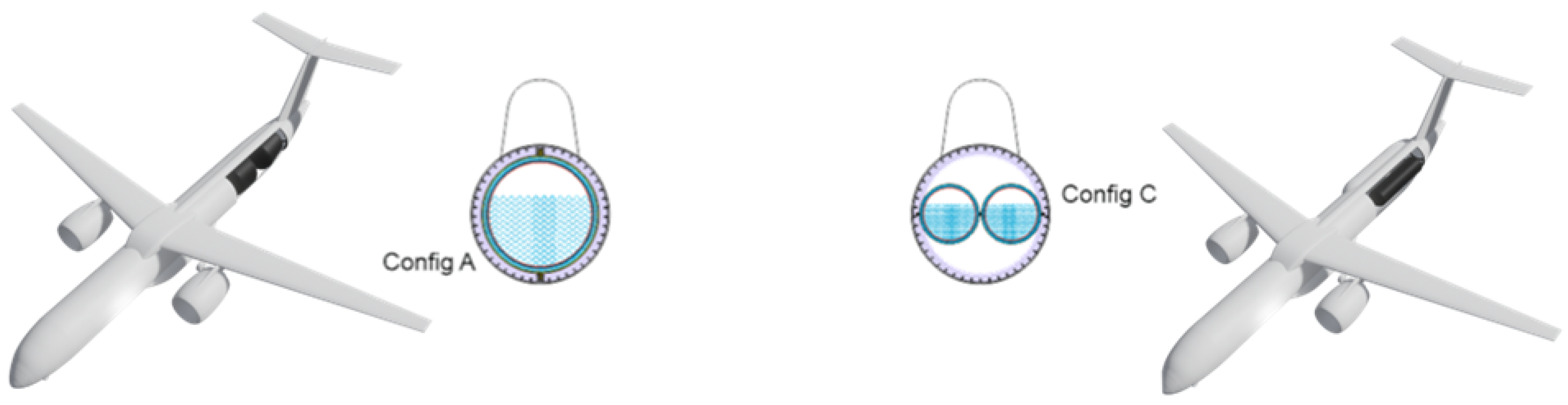
Figure 1). To satisfy the redundancy requirements essential in aircraft, two storage tanks are used. In the first configuration, hereafter “Config A,” the tanks are placed in a tandem (fore-aft) arrangement, with the front tank shaped as a cylinder and the second tapered (conical). In the second configuration, ”Config C”, the tanks are arranged side by side in the fuselage.
There are unresolved challenges especially for the hydrogen tank (e.g., manufacture, leak tightness or insulation performance). Some of these are addressed in the HyStor and TACOMA projects. The HyStor project ran from 2021 to 2023 and was funded by the state of Lower Saxony in Germany (N-Bank). Its objective was to produce a manufacturing demonstrator in the form of a “half-tank” and to deliver Life Cycle Inventory (LCI) data for subsequent LCC and LCA analyses. TACOMA follows on the work begun in HyStor and runs from 2023 until 2026. Supported by the national aviation funding program “LuFo”, TACOMA continues development of a cryogenic hydrogen tank and includes economic and ecological evaluation of the hydrogen tank.
In the HyStor and TACOMA projects, fictional/tentative tank geometries for manufacturing demonstrators were used. In HyStor, a tank was designed according to Config A, while in TACOMA a different configuration (Config C) was assumed. Since a complete LCI dataset was not yet available for TACOMA, data from HyStor were used as reference and scaled by a factor of ~2 based on volume to approximate the TACOMA dataset.
In general, the validity of such scaling approaches and the associated uncertainties depend on a variety of factors. A key aspect is the tank design itself, including the shell thickness, laminate lay-up, length-to-diameter ratio, and the geometric design of the domes. In addition, the applied manufacturing process plays a crucial role, as cryogenic tank structures can fundamentally be produced using either filament winding or Automated Fiber Placement (AFP), which differ significantly in material usage, process steps, and cost structure. For the scaling of manufacturing costs, it is furthermore essential that comparable cost structures are assumed, for example by considering identical or equivalent manufacturing environments, such as production by the same company using similar equipment and organizational setups.
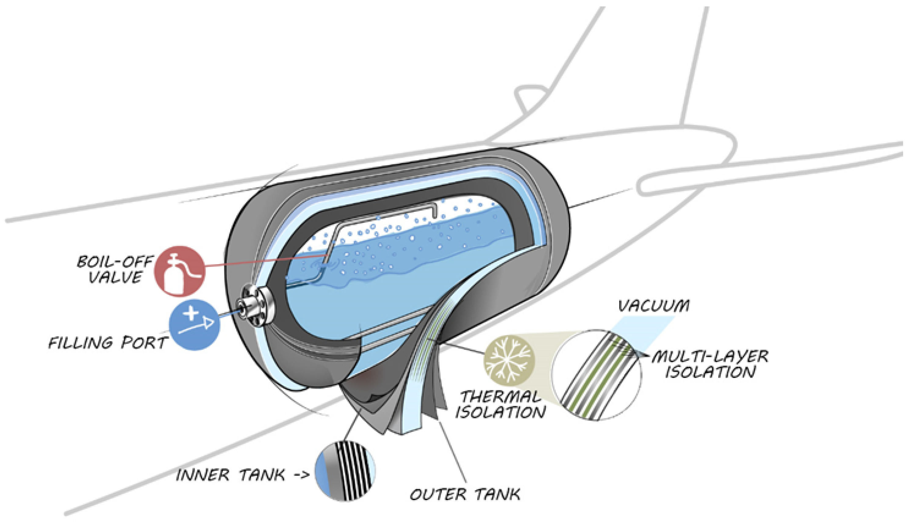
The hydrogen tank itself is double-walled, composed of an inner tank, a multi-layer insulation (MLI), and an outer tank shell (
Figure 2) [
9]. Between the inner and outer wall a vacuum is maintained to enhance insulation and thereby prevent undesired boil-off or warming of the liquid hydrogen. The tank system also includes ancillary components such as a filling port, a boil-off valve and more (e.g., sensors, baffle plates or a heating system).
As previously mentioned, several technical challenges still need to be overcome, and liquid hydrogen tanks for aviation applications are not yet commercially available, so its economical and ecological performance is unknown. This research shall support the assessment of the production of the composite tank shells.
2. Materials and Methods
In principle, a similar methodological framework can be applied for both LCA and LCC. The analysis begins with the definition of the goal and scope, which establishes the purpose of the study, the system boundaries, the key assumptions, and limitations. This phase determines the level of detail, the functional unit, and the intended audience or decision context in accordance with the ISO 14040/14044 standards for LCA [
10,
11].
Subsequently, the LCI is compiled, in which all relevant foreground process data are collected. This includes all input and output flows of materials and energy entering or leaving the system under study. For the cost analysis, additional parameters such as machine utilization, labor time, and process costs are recorded to enable a comprehensive cost allocation throughout the product’s life cycle.
In the following step, based on the LCI, the Life Cycle Impact Assessment (LCIA) and the cost assessment are performed to quantify the environmental and economic impacts, respectively. The LCIA translates the inventory results into impact categories such as global warming potential, resource depletion, or human toxicity, whereas the LCCA evaluates cost drivers and total costs [
12].
Finally, the results of both assessments are interpreted and evaluated in the interpretation phase, where the consistency, completeness, and significance of the outcomes are analyzed to support transparent and robust decision-making.
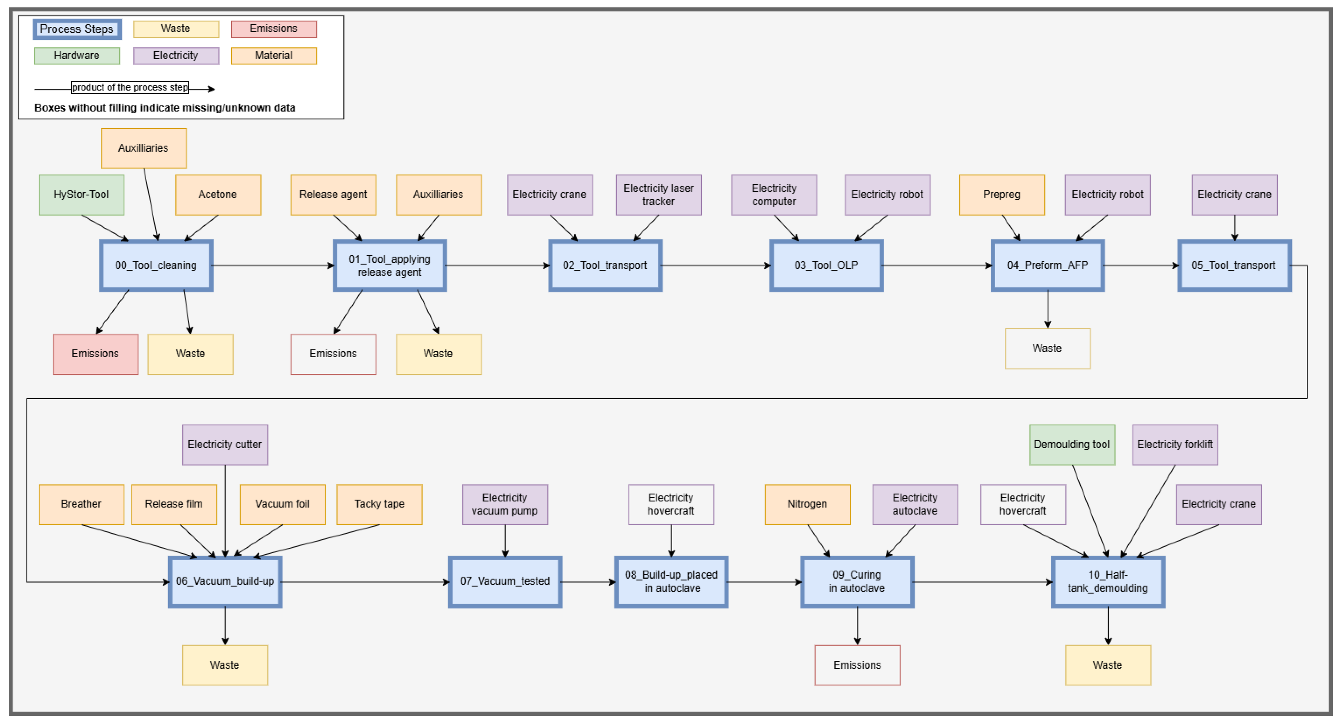
Within the HyStor project, a half-tank was manufactured as a production demonstrator in an industrial laboratory scale. This demonstrator served as the basis for the environmental and cost evaluation, and its LCI data were subsequently scaled to the full-tank planned in the TACOMA project. All process steps were analyzed following a cradle-to-gate system boundary. The process chain for the dome manufacturing (see
Figure 3) extends from tool cleaning to the demolding of the finished dome component. Each step includes detailed consideration of material input, waste output, machine operation, energy demand, and process duration to ensure a representative dataset for life-cycle evaluation.
Environmental impacts were calculated using the Environmental Footprint (EF) 3.1 method. For calculations, the open-source software openLCA was employed [
13]. Background data for material and energy flows were sourced from literature and the Ecoinvent 3.9.1 cut-off system model database, which provides consistent datasets for industrial processes and energy systems [
14]. The production activities are assumed to take place in Europe.
For the manufacturing of the half-tank in HyStor, the AFP layup technology was used with 16 quarter-inch prepreg tapes. Typically, composite tanks (e.g., for the pressurised storage of gases) are manufactured using filament winding, which offers high deposition rates and thus high manufacturing speeds. However, to avoid disadvantages of winding, such as laminate thickening in the dome areas, AFP was selected for HyStor. During the AFP layup process, a material scrap rate of approximately 10% was assumed and considered in the life cycle inventory. The AFP layup was performed using GroFi®, a multi-robot layup facility at the DLR site in Stade [
15].
3. Results
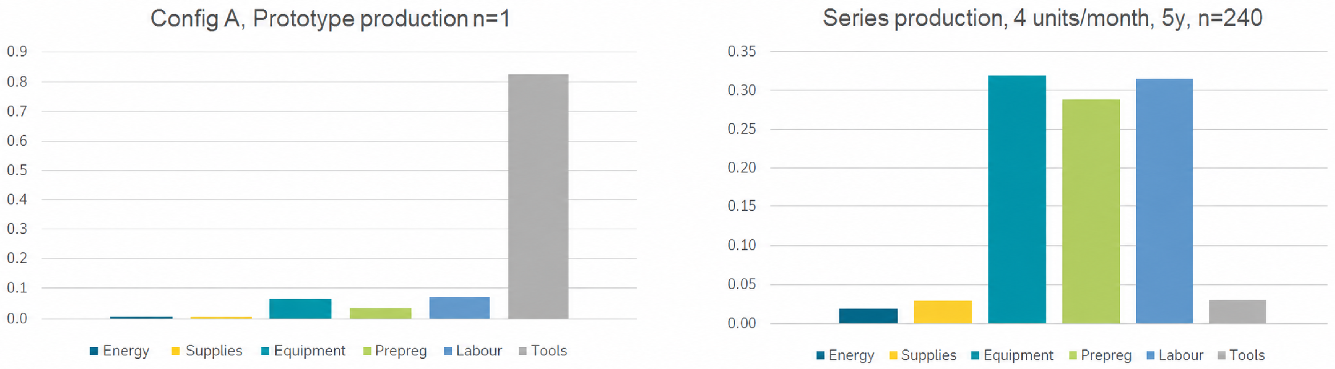
Figure 4 illustrates the production cost distribution for the Config A half-tank as a function of production volume. The left side of the figure represents a prototype production scenario with a single unit (
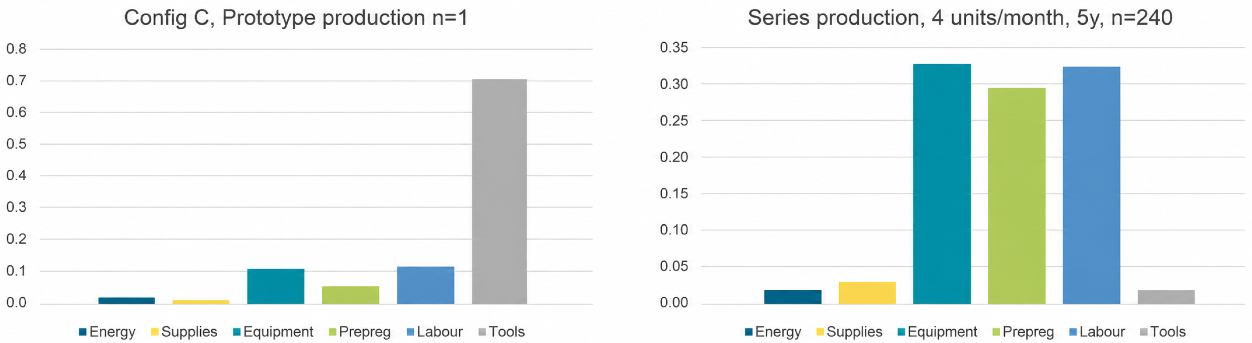
n = 1), while the right side depicts a serial production scenario assuming a manufacturing rate of four units per month over a five-year period, resulting in a total of 240 units. For the prototype production, it becomes evident that tooling costs—that is, the costs associated with the lay-up and curing tools—constitute the dominant cost category, accounting for more than 80% of total production costs. This strong influence reflects the high one-time investment required for tool fabrication. In contrast, for serial production, tooling costs become almost negligible when distributed over the total number of manufactured units. Instead, the equipment, carbon-fiber prepreg, and labor costs contribute approximately equally and collectively represent the majority share of total costs. When transitioning from prototype production to serial production, a cost reduction of approximately 89% can be achieved.
Figure 5 presents the production cost breakdown for the Config C tank, which is based on the scaled HyStor tank model. The tooling costs in this assessment correspond to the actual tool manufacturing expenses. As a result, the overall cost structure exhibits a similar pattern to that observed for Config A: tooling costs represent the dominant cost contributor, accounting for over 70% of total costs in the prototype production scenario. However, under serial production conditions, tooling costs again become negligible when distributed across the total production volume. Consequently, an overall cost reduction of approximately 81% can be achieved when transitioning from prototype to serial production.
Table 1 presents exemplary LCA results for all impact categories (EF3.1) of the Config C tank, based on the scaled dataset derived from Config A. For the impact category Climate Change, a total CO
2-equivalent of
was determined. In comparison, the Config A half-tank results in a CO
2-equivalent of
. These results are based on the use of a European electricity mix for the modeled production processes. It should be noted that higher climate change impacts would be expected if a Japanese electricity mix were assumed, considering the significant role of Japan in global carbon fiber manufacturing. This is reflected in the higher electricity-related emission factors for Japan implemented in the Ecoinvent database.
In addition to the table,
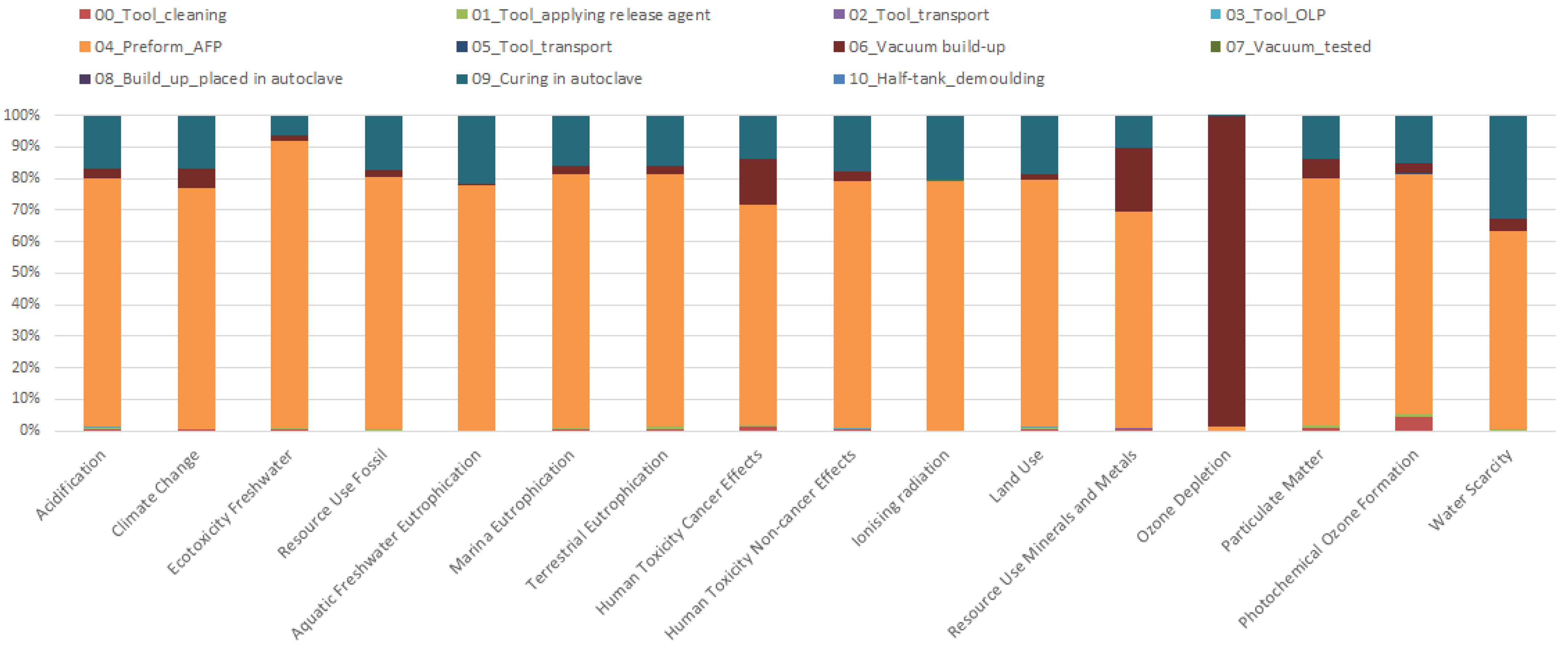
Figure 6 illustrates the relative contributions of individual process steps to the overall environmental impacts. It becomes evident that the preforming process using Automated Fiber Placement (AFP) represents the dominant contributor across nearly all impact categories. This high contribution originates primarily from the carbon-fiber prepreg material used in this step, whose production is associated with significant energy consumption and emissions related to carbon fiber manufacturing.
The second-largest impact arises from the autoclave curing process, mainly due to its substantial electricity demand required for heating and maintaining pressure during curing. Following these two steps, the vacuum bagging process shows the third-highest contribution, driven largely by the use of vacuum and release films with notable environmental footprints.
4. Discussion
This work presents the economic and environmental assessment of the inner tank shell of a double-walled liquid hydrogen aircraft tank, based on two design configurations. It introduces a combined evaluation approach founded on a shared LCI, enabling a consistent comparison of LCC and LCA results. The manufacturing process chain of the tank structure developed within the HyStor project was analyzed in detail.
The cost analysis reveals that tooling costs dominate in prototype production, representing the largest cost share. However, these costs decrease substantially when transitioning to serial production, where equipment, prepreg material, and labor constitute the majority of total costs. Equipment costs can be further reduced with increasing production volumes, as utilization rates and amortization effects improve. A similar, though smaller, effect can be expected for prepreg materials, since larger production volumes may allow for bulk purchasing and resulting supplier discounts. Labor costs, on the other hand, can mainly be reduced through a higher level of automation and further process optimization as production scales up.
Regarding the LCA results and their main process drivers, the AFP process—and the associated carbon-fiber prepreg material—were identified as the dominant contributors across nearly all impact categories. The autoclave curing process and the vacuum bagging setup follow at a noticeable distance. The carbon-fiber demand itself is largely dictated by structural requirements, particularly pressure resistance and leak tightness, and therefore offers only limited potential for direct reduction. Some process-level optimizations—such as increased AFP lay-up speed or minimized standby times—could marginally improve environmental performance. However, their influence remains minor compared to the material-related impact.
The autoclave curing process may offer greater optimization potential, such as tooling improvements (e.g., a reduced tooling mass or an optimized heating system) that could shorten cycle times. Yet, the overall reduction potential remains limited, as does that of the vacuum bagging process. Nevertheless, a carbon-fiber-reinforced hydrogen tank—in addition to the inherent benefits of using hydrogen as a fuel—offers a significant weight advantage compared to a metallic design. Although the present study is limited to a cradle-to-gate assessment of the tank manufacturing stage, previous studies indicate that such weight reductions can lead to substantial operational fuel savings over an aircraft’s lifetime. These potential benefits are not quantified within this work and are therefore referenced only qualitatively based on the external literature [
16]. A comprehensive evaluation of the environmental payback would require a full life-cycle assessment including operational and end-of-life phases, which is beyond the scope of this study.
Looking ahead, future work will focus on collecting specific LCI data for the Config C tank developed within the TACOMA project. These data will enable a complete life cycle evaluation of the full inner tank configuration. For a comprehensive assessment of the entire tank system, additional data on the insulation layer, outer tank, and system components will be required. Addressing these aspects should be a priority in future research projects to further refine the environmental and economic understanding of cryogenic hydrogen storage systems for aviation.