1. Introduction
As the aerospace industry shifts towards sustainability and cost-effectiveness, the development of lightweight structures that satisfy multiple, often competing, constraints has become central. Structural optimization based on accurate Global Finite-Element Models (GFEMs) is a powerful tool for physics-based assessment of candidate designs. At the same time, composite materials have greatly improved structural efficiency due to their high strength-to-weight ratio and integration potential, but also increase modeling complexity owing to the large number of design parameters.
Despite advances in computational power and tools, creating and modifying detailed wing models remains largely a manual and time-consuming task. As a result, conceptual studies traditionally rely on legacy data and empirical formulas derived from conventional configurations, while more rigorous FE-based approaches are postponed to later stages-an approach that limits accuracy and is poorly suited for novel aircraft concepts [
1]. Employing structural optimization techniques from an early development stage would increase the fidelity of estimations and the ability to make more informed decisions from the conceptual design stage onward; however, tools are required for rapid generation of structural models. To this end, several efforts have been made in recent years to develop structural design automation tools. Ref. [
2] developed a knowledge-based tool for parametric wing modeling based on CATIA and Patran, aimed at speeding pre-processing in preliminary design. Similarly, ref. [
3] presented the ELWIS tool, suitable for the creation of detailed wing models in ANSYS using the CPACS input format. Ref. [
4] proposed OptWing for automatic model generation and sizing on arbitrary Outer Mold Lines (OMLs), albeit with relatively simple models. Finally, ref. [
5] presented GRASP, which automatically places ribs/spars within an OML using a branch-and-cut search and then builds the structural mesh, and identified layouts that minimize tip deflection. While these tools enable rapid model generation at varying fidelity, end-to-end frameworks that couple internal layout optimization with sizing on arbitrary parametric wings, and especially with composite materials, remain sparsely documented.
An efficient framework that enables the investigation and optimization of novel configurations from early design stages is proposed in this work. A flexible tool has been developed for the automatic generation of the structural model of an arbitrary parametric wing geometry. Coded in Python 3.12 and TCL (HyperMesh 2023 native command language), the tool creates a 2D GFEM mesh of the desired wing configuration, and allows for composite ply-based modeling, and can automatically apply boundary conditions and load cases. Finally, the model created is readily available for sizing optimization with Optistruct by incorporating user-defined design variables and constraints.
Design of Experiment (DoE) combined with surrogate models is a common strategy to reduce the number of expensive FE-based sizing runs in early stages. In Ref. [
6], DoE-based regression models were developed based on FEM results and shown to produce accurate early predictions of mass and response metrics. Earlier work of Ref. [
7] demonstrated that simple Gaussian Process models (Kriging) can be effective tools for global optimization and outperform response-surface methods. Ref. [
8] further compared different approximation models applied to multidisciplinary wing design and found that Kriging models can often outperform alternative metamodels (Artificial Neural Networks) when data is limited.
Within the proposed framework, a DoE is initially conducted to evaluate how structural-layout parameters affect mass and generate a data set. For each design, a gradient-based sizing optimization is performed to acquire the minimum mass. A strategy is used to mitigate the effect of local minima and achieve more reliable solutions. Finally, the use of surrogate models as a means to identify lightweight, constraint-satisfying designs more efficiently is investigated. A Random Forest model is fitted as a preliminary baseline, while more advanced GP models will be implemented in future work to enable Efficient Global Optimization (EGO).
2. Methodology
2.1. Wing Parametric Geometry Definition
The workflow begins with the definition of the wing outer geometry. A plethora of input parameters is available, allowing for the rapid generation of arbitrary wing geometries. After the outer geometry is defined, the internal structural layout is specified.
Table 1 lists the available parameters for geometry and layout definition. A TCL script is generated to create the required geometrical surface entities in the HyperMesh environment, with all components modeled in 2D. In the current implementation, stringers are restricted to a T-section, with flange and web dimensions as modifiable parameters.
2.2. Finite Element Model Generation
2.2.1. Mesh and Test Model Description
The next step involves meshing the 2D surfaces with predominantly quadrilateral shell elements, with triangular elements used only in transition regions. The surface mesh is created automatically with a user-defined element density for each component, ensuring that adjacent components share nodes.
A representative transport aircraft wing (S = 160 m
2,
,
) is chosen as the reference structure to demonstrate the developed framework.
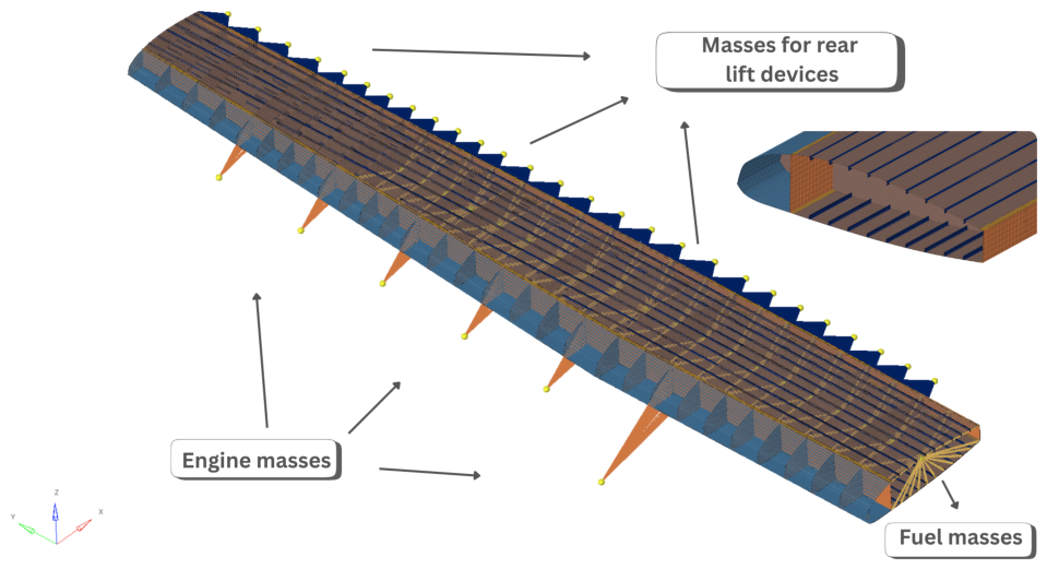
Figure 1 shows the reference wing FE model. Several types of additional non-structural concentrated masses are included in the model to improve accuracy. The reference wing employed a hybrid distributed propulsion configuration, involving 5 electric motors per semi-wing, modeled as concentrated masses along the span, in addition to a larger mass representative of a turboprop engine near the kink (
Figure 1). The wing trailing edge is replaced by concentrated masses which simulate the rear structure and high lift devices. Finally, fuel masses are considered in the wing box area, and up to
of the span. All concentrated masses are connected to the structure via RBE3 elements tied to automatically selected attachment nodes. These additional masses are optional and user-configurable.
2.2.2. Material and Element Properties
Material properties are user inputs and can be isotropic (metallic) or composite laminates. Ribs are modeled in Aluminum 7010-T651, while the remaining components are modeled as composite laminates of unidirectional Carbon-Fiber-Reinforced Plastic (CFRP) plies.
Table 2 lists the mechanical properties.
Regarding 2D element property definitions, PSHELL is used for metallic components, while the ply-based approach, available in HyperMesh, is adopted for composite laminates via PCOMPP. Ply orientations, thicknesses, shapes, and ply drops are defined at this stage. The specific selections for the present case are detailed in the following subsection.
2.2.3. Boundary Conditions
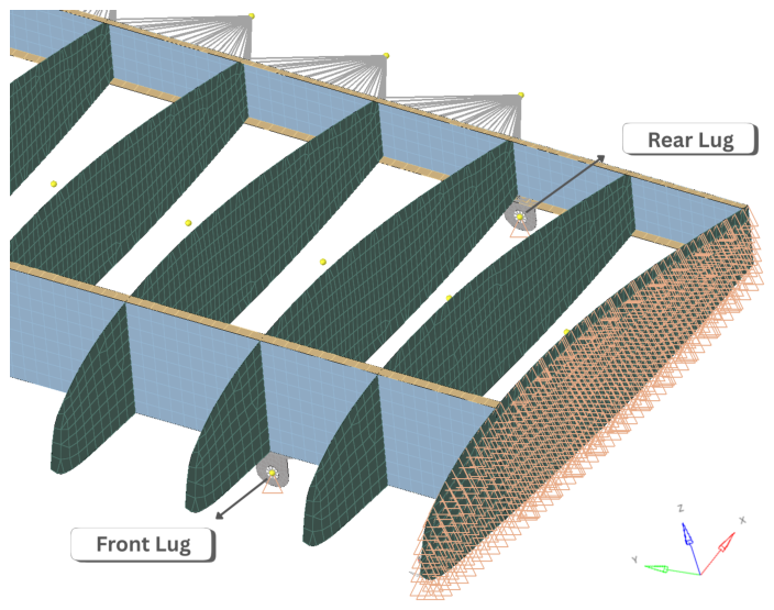
The reference configuration is a high-wing cantilever, with boundary conditions shown in
Figure 2. Connecting lugs are positioned at the front and rear spars to represent the structural attachments to the fuselage. The front lug is constrained in the
x- and
z-directions, while the rear lug is constrained in the
z-direction only. Additionally, symmetry boundary conditions are applied in the
-plane at the wing root.
2.3. Sizing Optimization
2.3.1. Design Variables and Composite Definition
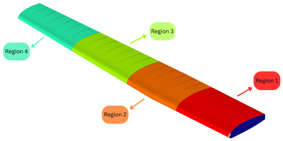
To find the optimum thickness distribution, the wing is divided into 4 zones along the span (
Figure 3). The number of optimization regions is an available parameter. Each zone defines a specific ply shape for each composite component. The considered plies have orientations of [0°/±45°/90°] and the 10% rule is satisfied in all laminates to mitigate the risk of unexpected load paths. In the current implementation, smeared properties are considered, and the stacking sequence is not subjected to optimization. Design variables are assigned to the thickness of each ply orientation, for each component and optimization zone. The components are: upper/lower skins, front/rear spar webs, front/rear spar caps, upper/lower stringers, and ribs. Ply thickness design variables are discrete and multiples of the manufacturing thickness set to 0.181 mm. Ply drop constraints and maximum thickness may also be implemented on the laminate level via
DCOMP cards. Additionally, design variables are defined for the aluminum shell thickness for the components in each section. This results in a total of 100 design variables for the wing sizing.
2.3.2. Load Cases and Constraints
Two aerodynamic limit load cases are considered, a pull-up maneuver with a load factor of +2.5 g and a pull-down maneuver of −1 g, with corresponding ultimate load factors of +3.75 g and −1.5 g, respectively. Aerodynamic loads are computed using the Athena Vortex Lattice (AVL) code, and applied as pressure loads on each skin element. Since the OML of the wing is fixed, these loads remain constant. Inertial loads are included as well.
Regarding constraints, an ultimate strain constraint of was applied to the in-plane major and minor principal strains () of the composite plies in both tension and compression, consistent with a damage-tolerance Barely Visible Damage (VBD) no-growth capability approach. For aluminum components, the non-yielding criterion at the limit load is applied based on Von Mises stress. The allowable stress is set to of the yield strength, equivalent to 343 MPa, to account for preliminary fatigue and damage tolerance considerations. These strength constraints are enforced on both the top and bottom surfaces of each shell element. Structural stability is ensured by imposing no-buckling constraints up to ultimate load conditions, requiring all eigenvalues from linear buckling analyses at limit load to be greater than 1.5.
3. Wing Test-Case Results and Discussion
3.1. DoE Setup
To assess the flexibility and performance of the developed framework, a full-factorial DoE is carried out on three internal layout parameters: front spar location as a percentage of chord,
; number of ribs,
; and number of stringers,
, with the objective of quantifying their effect on mass. Each parameter is assigned four levels, yielding
samples:
,
, and
. For each configuration, the mass is obtained via size optimization using OptiStruct’s gradient-based algorithm with a staged multi-run strategy. The first run seeks a feasible design, while subsequent runs impose a mass constraint equal to
of the best mass found so far, relaxing it if an infeasible solution is encountered. Compared to a simple multi-start global search strategy [
10], this approach is more computationally time-efficient and often yields additional mass reductions of up to about
between the first and final runs, leading to more reliable minima.
3.2. DoE Results
It was observed that configurations with similar layouts may occasionally yield noticeably different optimized masses. This is because the sizing problem is discrete (composites) and multi-modal: constraints are pushed to the limits, and the active set can change between runs (i.e., different critical buckling mode, shifts in the critical strain/stress region), creating hard corners in the design space. Additionally, a limiting factor of the designed procedure involves the tendency of Optistruct’s gradient-based algorithm to reach local minima, introducing error in the mass corresponding to each configuration. Finally, numerical irregularities from meshing or solver tolerances can add additional “noise”.
To visualize the underlying trends in a meaningful way,
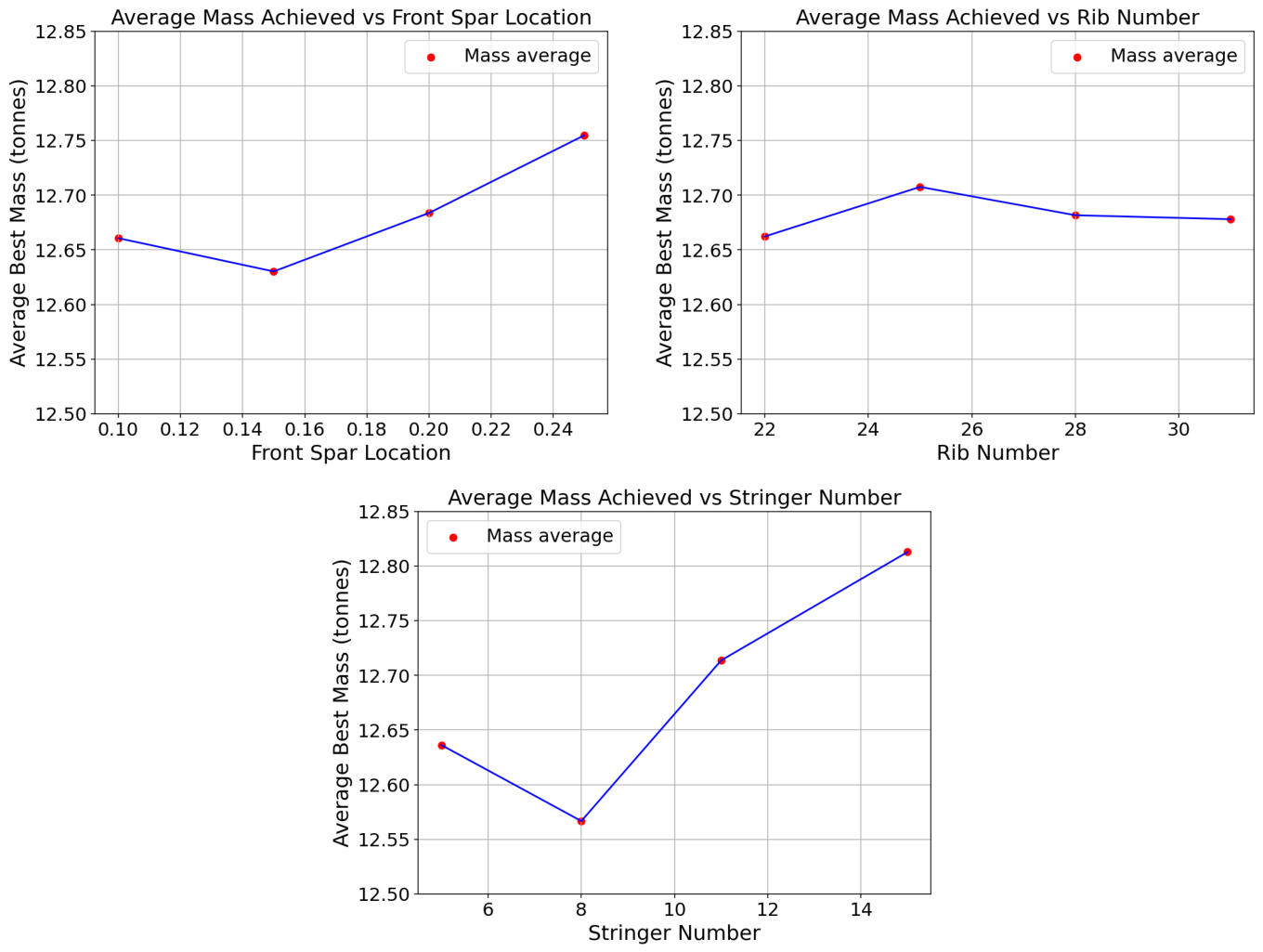
Figure 4 plots the average optimized mass versus each level value for each parameter.
The following behaviors can be deduced from the plot. Moving the front spar aft of of the local chord tends to increase mass, due to high loads near the leading edge that require an effective load path through the front spar. Increasing the number of stringers initially reduces mass by improving panel stability, but beyond , the material penalty outweighs stability gains, producing a net increase. Rib number in the range studied has a relatively weak effect on structural mass: aluminum ribs are consistently sized to low thicknesses across all designs, indicating they are not critical components and contribute modestly to global stiffness.
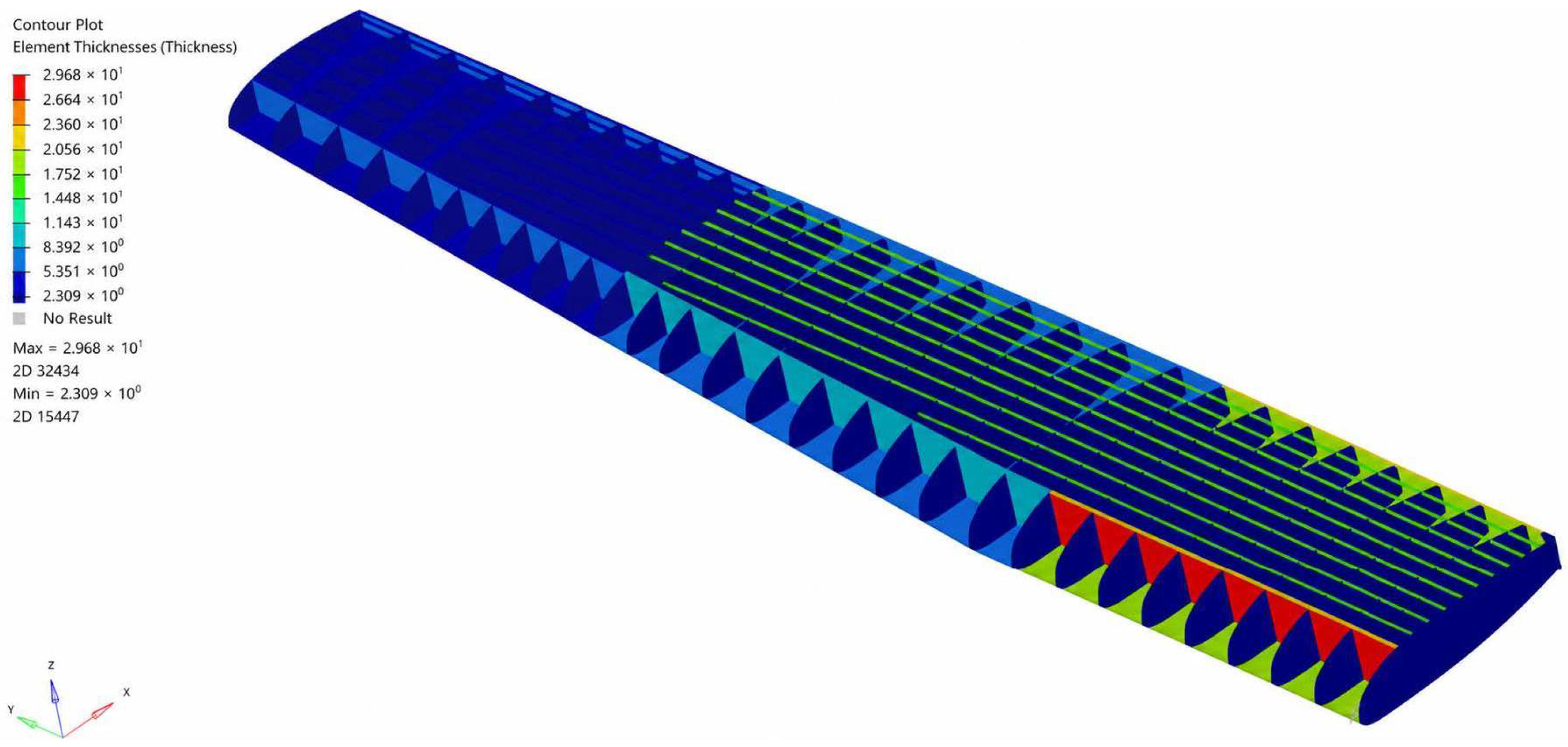
Figure 5 shows an example of optimized thickness distribution. Among the 64 layouts, the lightest configuration features
,
, and a front-spar location at
. While design trends and a feasible lightweight solution can be determined using the DoE, a better design could be found by exploiting the data set to create a surrogate model.
3.3. Preliminary Surrogate Model
A
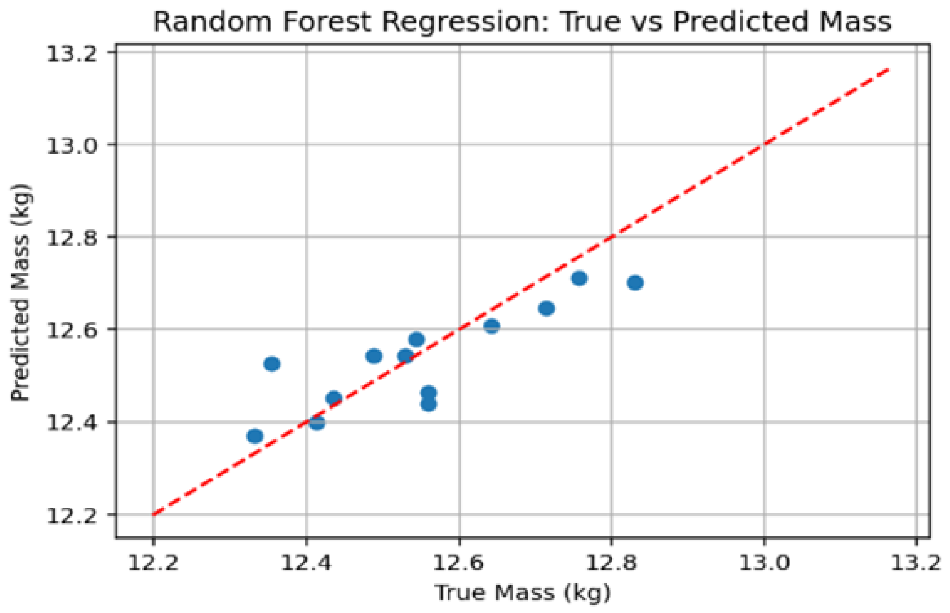
Random Forest (RF) regressor is trained using the DoE points to map the (minimized) mass according to the three internal structure layout parameters, effectively replacing the size optimization step. Random Forests are chosen initially because they require minimal hyperparameter tuning and are robust to moderate noise. Additionally, they offer insights into the RF feature importances of each parameter, which confirm that stringer count has the most significant effect, followed by front spar location. A set of 13 points is reserved for cross-validation, with the final model achieving a Root Mean Squared Error (RMSE) of
, indicating that trends in the data set can be learned to some extent.
Figure 6 shows the parity plot of the data based on the RF regressor.
4. Conclusions
An automated framework based on Python and TCL has been presented for the parametric generation and sizing of composite wing FE models. Control over a wide range of geometry parameters enables rapid exploration of alternative designs and a physics-based approach during the conceptual design phase. The framework is assessed in a lug-supported transport wing by conducting a DoE on the effect of three internal layout parameters: front spar location, number of ribs, and number of stringers, on structural mass. For each configuration, a size-optimization-ready GFEM model is automatically created, featuring ply-based composite properties and user-defined design variables and constraints.
The DoE revealed that the parameters are interdependent, with different configurations inducing different load and thickness distributions. Underlying trends show that (1) moving the front spar aft of 15% of the chord results in heavier designs; (2) the number of stringers has a sweet spot, , after which the overall weight increases; and (3) aluminum ribs are consistently sized to low thickness and have comparatively less influence on the wing response. A Random Forest regressor trained on the DoE data yields feature-importance values that are similar, confirming that the relationships are learnable from the data.
Despite current limitations (e.g., local minima sensitivity), it is concluded that the automated framework can be effectively used as a tool for coupled internal structural layout and size optimization, enabling early, physics-based weight estimation of alternative design solutions. Future work will investigate Gaussian-process surrogates that quantify uncertainty, can be better tuned, and enable Efficient Global Optimization (EGO).
Author Contributions
Conceptualization, N.Z. and A.C.; methodology, N.Z. and A.C.; software, N.Z.; validation, N.Z.; formal analysis, N.Z.; investigation, N.Z.; resources, N.Z. and A.C.; data curation, N.Z.; writing—original draft preparation, N.Z.; writing—review and editing, A.C.; visualization, N.Z.; supervision, A.C. All authors have read and agreed to the published version of the manuscript.
Funding
This research was carried out within the project TIFON (Tecnologías Inteligentes para la Fabricación, el diseño y las Operaciones en entornos iNdustriales), coordinated by Universidad Politécnica de Madrid (UPM), funded by the Spanish Agencia Estatal de Investigación (AEI) under the “Programa Transmisiones”, grant No. PLEC2023-010251.
Institutional Review Board Statement
Not applicable.
Informed Consent Statement
Not applicable.
Data Availability Statement
Data and scripts are available upon reasonable request.
Conflicts of Interest
The authors declare no conflicts of interest.
References
- Dababneh, O.; Kipouros, T. A review of aircraft wing mass estimation methods. Aerosp. Sci. Technol. 2018, 72, 256–266. [Google Scholar] [CrossRef] [Scilit]
- Tang, J.; Xi, P.; Zhang, B.; Hu, B. A finite element parametric modeling technique of aircraft wing structures. Chin. J. Aeronaut. 2013, 26, 1202–1210. [Google Scholar] [CrossRef] [Scilit]
- Dorbath, F.; Nagel, B.; Gollnick, V. A Knowledge Based Approach for Automated Modelling of Extended Wing Structures in Preliminary Aircraft Design. In Proceedings of the Deutscher Luft- und Raumfahrtkongress (DLRK) 2011, Bremen, Germany, 27–29 September 2011. [Google Scholar]
- Sensmeier, M.; Samareh, J. Automatic Aircraft Structural Topology Generation for Multidisciplinary Optimization and Weight Estimation. In Proceedings of the 46th AIAA/ASME/ASCE/AHS/ASC Structures, Structural Dynamics and Materials Conference; American Institute of Aeronautics and Astronautics: Reston, VA, USA, 2005. [Google Scholar] [CrossRef] [Scilit]
- Clough, J.L.; Oberai, A.A.; Zakrajsek, A.J. Automated Wing Internal Structure Placement Guided by Finite Element Analysis. In Proceedings of the AIAA Aviation 2019 Forum; American Institute of Aeronautics and Astronautics: Reston, VA, USA, 2019. [Google Scholar] [CrossRef] [Scilit]
- Cipolla, V.; Abu Salem, K.; Palaia, G.; Binante, V.; Zanetti, D. A DoE-based approach for the implementation of structural surrogate models in the early stage design of box-wing aircraft. Aerosp. Sci. Technol. 2021, 117, 106968. [Google Scholar] [CrossRef] [Scilit]
- Simpson, T.W.; Mauery, T.M.; Korte, J.J.; Mistree, F. Kriging Models for Global Approximation in Simulation-Based Multidisciplinary Design Optimization. AIAA J. 2001, 39, 2233–2241. [Google Scholar] [CrossRef] [Scilit] [PubMed]
- Paiva, R.M.; Carvalho, A.R.D.; Crawford, C.; Suleman, A. Comparison of Surrogate Models in a Multidisciplinary Optimization Framework for Wing Design. AIAA J. 2012, 48, 995–1006. [Google Scholar] [CrossRef] [Scilit]
- Marlett, K. HEXCEL 8552 IM7 Unidirectional Prepreg 190 gsm 35% RC Qualification Statistical Analysis Report; Rept. NCP-RP-2009-028 Rev. B; Technical Report; National Institute for Aviation Research: Wichita, KS, USA, 2011. [Google Scholar]
- Cini, A.; Popov, A.; Ratchev, S. Minimum weight structural optimisation procedure for the preliminary sizing of a composite wing of a compound helicopter. In Proceedings of the 6th Aircraft Structural Design Conference, Bristol, UK, 9–11 October 2018. [Google Scholar]
| Disclaimer/Publisher’s Note: The statements, opinions and data contained in all publications are solely those of the individual author(s) and contributor(s) and not of MDPI and/or the editor(s). MDPI and/or the editor(s) disclaim responsibility for any injury to people or property resulting from any ideas, methods, instructions or products referred to in the content. |