Article

Ce–Zr Promoted Ni-Structured Catalysts on SiC Open-Cell Foams for Efficient Electrified Steam Reforming of Biomethane


by
Daniela De Cata
1,2,*,†,
Lorenzo De Paola
1,2,†,
Pietro Colucci
1,
Vincenzo Piemonte
2,
Francesca Santoni
1 and
Alberto Giaconia
1
1
Laboratory for Hydrogen and New Energy Vectors (H2V), Department of Energy Technologies and Renewable Sources, ENEA Casaccia Research Center, Via Anguillarese 301, 00123 Rome, Italy
2
Unit of Chemical-Physics Fundamentals in Chemical Engineering, Faculty of Engineering, University Campus Bio-Medico of Rome, Via Alvaro Del Portillo, 21, 00128 Rome, Italy
*
Author to whom correspondence should be addressed.
†
These authors contributed equally to this work.
Hydrogen 2026, 7(3), 111; https://doi.org/10.3390/hydrogen7030111
Submission received: 9 July 2026 / Revised: 1 August 2026 / Accepted: 5 August 2026 / Published: 6 August 2026
(This article belongs to the Special Issue Green Hydrogen Production)

Abstract

Electrified steam methane reforming (eSMR) is emerging as a promising technology for the decarbonization of the chemical industry and low-carbon hydrogen production by coupling renewable electricity with renewable gaseous feedstocks such as biomethane. In this work, structured Ni-based catalysts washcoated on highly thermally conductive SiC open-cell foams (OCFs) were developed and evaluated for biomethane steam-reforming operating conditions. Two catalyst formulations, 30 wt.% Al2O3_30 wt.% CeO2_20 wt.%Ni and SiC_30 wt.% Al2O3_30 wt.%Ce0.25Zr0.75 O2_20 wt.%Ni, were tested in a laboratory-scale indirectly electrically heated reformer. The high thermal conductivity of the SiC-structured support ensured efficient heat transfer throughout the reactor, limiting radial temperature gradients to below 10 °C. Both catalyst formulations exhibited excellent catalytic performance; however, the Ce0.25Zr0.75O2-promoted catalyst achieved the best results, maintaining equilibrium methane conversion at a gas hourly space velocity above 7000 h−1 while reaching a specific electrical energy consumption of 2.06 kWh/Nm3 of produced H2 projected for industrial-scale efficiency. Notably, these performances were obtained with a catalyst loading approximately 20–50% lower than that of conventional commercial alumina pellet catalysts. XRD characterization did not reveal the formation of crystalline graphitic carbon after catalytic operation. Furthermore, the structural evolution of the Ce–Zr–O highlights the active role of the mixed oxide in promoting redox processes and maintaining catalytic activity under reaction conditions. Overall, these results demonstrate that the combination of highly conductive SiC-structured supports and Ce–Zr-promoted Ni catalysts significantly enhances both the thermal and catalytic efficiency of eSMR. The proposed catalyst provides a promising route toward compact, energy-efficient, and decentralized hydrogen production from biomethane, supporting the electrification and decarbonization of future hydrogen generation technologies.

1. Introduction

According to the IEA’s Sustainable Development Scenario, achieving the climate target of limiting global warming to 1.5 °C above pre-industrial levels requires reducing CO2 emissions from the energy and industrial sectors by around 40% by 2030 [1]. The chemical industry is a major energy consumer and remains heavily dependent on fossil fuel combustion for supplying high-temperature heat [2,3]. In this context, improving efficiency, electrifying processes, and replacing fossil fuels with low-emission sources are crucial to reaching the net-zero goal by 2050 [1,4].
On the one hand, electrification of industrial processes represents a key decarbonization strategy where power generation is decarbonized. In a net-zero scenario, high-energy-intensive carriers and fuels are required to drive so-called hard-to-abate (or hard-to-electrify) sectors. In this context, hydrogen is considered a key energy carrier for decarbonization due to its high energy density per unit mass (LHV = 120 MJ/kg) and zero CO2 emissions during its combustion [5,6]. Currently, the vast majority of global hydrogen production is still derived from fossil fuels, while low-emissions hydrogen accounts for less than 1% of total production, highlighting the urgent need for more sustainable hydrogen production pathways [7,8,9]. Steam methane reforming (SMR) is the dominant hydrogen production method, accounting for almost half of the global hydrogen demand. The process involves the reaction of methane with steam (Equation (1)) followed by the water–gas shift reaction (Equation (2)) to maximize hydrogen production [7,10].
SMR :   C H 4 + H 2 O   ⇌ C O + 3 H 2
WGS :   C O + H 2 O   ⇌   C O 2 + H 2
The process is globally endothermic, and, in industrial applications, SMR is carried out at high temperatures (850–950 °C) and relatively high pressures (20–40 bar). The heat is typically provided through radiation by the combustion of natural gas in the reformer furnace and transferred via radiation [11]. This configuration leads to significant CO2 emissions, both from the chemical reactions and from fuel combustion, resulting in approximately 8–11 tons of CO2 per ton of H2 [8]. Although carbon-free alternatives such as water electrolysis are being developed, their high cost and electricity consumption (approximately 55 kWhe/kgH2) are currently limiting their large-scale deployment [5,12,13,14]. As a result, at present, SMR still remains a mature and widespread method for H2 production due to its efficiency and cost-effectiveness [15].
To reduce the associated emissions and promote sustainability, alternative ways to supply heat to the SMR process other than using fossil fuel combustion have been proposed. One promising alternative is the electrified steam methane reforming (eSMR) process [16]. In this configuration, furnaces are replaced by electric heating systems. Electrification can be direct, where heat is applied to a conductive catalyst support, or indirect, where heat is transferred at the catalytic bed through reactor walls or internal heating elements. Indirect electrification typically uses resistive heating, while direct electrification can use resistive, inductive, or microwave heating [16].
As electricity can be supplied from renewable energy sources, this approach offers a promising pathway for reducing emissions in energy-intensive hard-to-abate industrial sectors [17]. Besides the associated CO2 emissions, limitations of conventional steam-reforming technology are also related to the reactor design. The main challenges are: (1) inefficient heat transfer in the furnace from the radiative heat source to the reforming catalyst; (2) the requirement for high operating temperatures, resulting in expensive construction materials (super alloys) and high maintenance costs; and (3) a low catalyst effectiveness factor (2–10%) resulting from the low thermal conductivity of conventional alumina-supported catalyst pellets, which leads to steep thermal gradients across the reactor wall and catalyst bed [18,19].
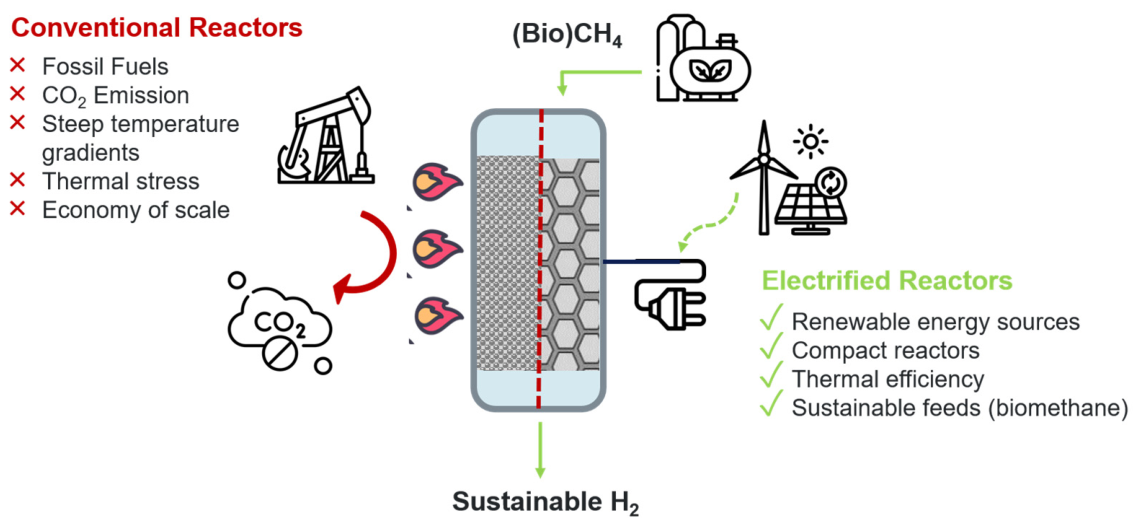
Optimal reactor design and electrification of steam methane reforming systems (eSMR) can significantly improve heat transfer by ensuring intimate contact between the heat source and the catalytic bed. This allows the delivery of heat directly to the reaction zone, thereby improving energy efficiency, reducing heat losses and enhancing catalytic performance. Additionally, replacing the high-volume combustion chamber with an electric heating system makes the reactor more compact and mitigates the impact of economies of scale [8,20]. The development of more compact reactor configurations also makes eSMR suitable for processing lower feedstock flow rates, such as those associated with biomass-derived biogas and biomethane. This increases the potential for integrating sustainable sources into hydrogen production, providing further environmental benefits and supporting circular economy strategies. These benefits are particularly relevant considering that electrification is not limited to steam methane reforming but can also be applied to several endothermic processes in general. This highlights its potential impact on industrial decarbonization and process intensification (Figure 1) [21,22,23].
Structured catalyst supports made from highly thermally conductive materials, such as silicon carbide (SiC), improve heat transfer, enabling a more uniform radial temperature profile and reducing hotspots. These catalysts can be designed as monolithic heating elements or foams [2,24,25]. Focusing on resistive heating, Ambrosetti et al. [25] proposed a tubular stainless-steel reactor loaded with a structured catalyst with an inner copper cable as the heating element. Through evaluating various support materials (copper, stainless steel and SiC) and geometries (open-cell foams and honeycomb monoliths), they identified SiC open-cell foams (OCFs) as the best option. This configuration combines the superior external mass transfer properties of foams with the high thermal conductivity of SiC, resulting in improved catalyst performance.
Regarding the catalyst formulation, although noble metals (such as rhodium, palladium, platinum, ruthenium, and cobalt) have been widely studied as active catalyst components [26,27,28], nickel remains the most used due to its good performance, relatively low cost, and low environmental impact in terms of extraction and disposal [29,30]. Additionally, catalyst performance can be enhanced using some oxides as promoters, such as ceria and zirconia. In fact, although not catalytically active, these species enhance oxygen mobility and reduce internal diffusion limitations, thereby promoting oxidation reactions and mitigating coke formation. Sekine et al. [31] reported that catalytic activity increases as the Ce/Zr ratio decreases for the SMR reaction. Regarding eSMR applications, Meloni et al. [32] reported promising results using a structured catalyst consisting of oxygen-bonded silicon carbide (OB-SiC) open-cell foams washcoated in Ni_CeO2_Al2O3. The catalytic bed was indirectly heated by the Joule effect through an inner conductive cable. The proposed catalyst enabled conversions close to equilibrium at 720 °C. An energy consumption of 2.2 kWh/Nm3 H2 was achieved at a WHSV of 2 h−1 [32].
The work presented in this paper focuses on the development of an innovative and efficient catalyst for the electrified SMR of biomethane. The catalyst was washcoated on high-conductive SiC OCF supports. Nickel was selected as the active component, while cerium oxide and ceria–zirconia oxide were used as promoters to enhance catalytic activity. Two catalyst formulations were evaluated: SiC_30%Al2O3_30%Ce_20%Ni and SiC_30%Al2O3_30%Ce/Zr_20%Ni. Based on the findings of [31], a Zr-rich Ce–Zr promoter with a Ce/Zr molar ratio of 0.33 was selected in this study to exploit the beneficial effect of zirconium on the catalytic performance. Since indirect resistive heating is currently the most mature electrification strategy, it was adopted to focus primarily on catalyst design performance [16]. The experiments were performed at atmospheric pressure, which is representative of the conditions of biomethane outlet streams from anaerobic digestion plants after biogas upgrading, and at a reactor temperature of 750 °C. The effect of methane feed flow rate, and consequently, gas hourly space velocity (GHSV), on catalyst performance was evaluated in terms of CH4 conversion and H2 selectivity. The aim of this study is to provide an experimental assessment of electrified steam methane reforming for hydrogen production from biomethane, with a specific focus on investigating the influence of Ce- and Ce/Zr-promoted Ni catalysts under operating conditions representative of eSMR applications. The findings of this work are expected to contribute to the development of efficient and sustainable electrified reforming technologies for hydrogen production.

2. Materials and Methods

2.1. Catalyst Preparation

In this work, a commercial silicon carbide (SiC) open-cell foam with a cylindrical geometry (diameter = 4.5 cm; length = 2.5 cm; 20 p.p.i.; %wt > 95%) was used as a structured catalyst support. The coating was applied through a dip-coating method proposed by [32]. The SiC foams were immersed for 20 min in a washcoat slurry composed of distilled water, pseudo-boehmite (4.6 wt%), γ-alumina (15.4 wt%, <50 nm; Sigma-Aldrich, St. Louis, MO, USA), and methylcellulose (1 wt%, viscosity 15 cP; Sigma-Aldrich, St. Louis, MO, USA) at pH = 3 (adjusted by HNO3). The excess slurry was removed by centrifugation at 1500 rpm for 5 min and the coated samples were dried at 120 °C for 2 h, followed by calcination at 450 °C for a further 2 h. This coating cycle was repeated about 8–9 times until the target washcoat loading of 30 wt% relative to the SiC support mass was achieved.
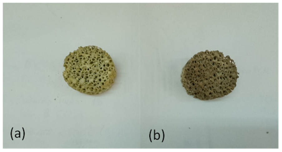
CeO2 or Ce0.25Zr0.75O2 were then introduced as promoters by wet impregnation, with a loading equivalent to 30 wt% of the washcoat mass. Ceria and zirconia are considered excellent promoters, thanks to their high oxygen storage capacity. In fact, they are actively involved in reversible redox reactions to enhance the catalytic activity of supported catalysts, leading to improved reaction rates. Moreover, CeO2 and Ce0.25Zr0.75O2 also have basic properties, which can inhibit coke formation, resulting in more stable catalysts [33,34,35]. The required amounts of Ce(NO3)3 ∙ 6H2O and ZrO(NO3)2 ∙ 2H2O were dissolved in water to form an aqueous solution, which was then used to impregnate the washcoated foams. The samples were then dried and calcined at 450 °C for 2 h to remove the nitrate group from the precursor. The active phase, nickel, was then deposited by wet impregnation using a Ni(NO3)2 aqueous solution. The nickel loading was fixed at 20 wt% with respect to the combined mass of the alumina washcoat and oxide promoter. The total amount in grams of each component of the catalyst is reported in Table 1. Finally, the resulting samples were calcined at 900 °C for 2 h. Figure 2 shows two catalyst samples (SiC_30%Al2O3_30%CeO2_20%Ni, hereafter Ce_Ni, and SiC_30%Al2O3_30%Ce0.25Zr0.75O2_20%Ni, hereafter Ce/Zr_Ni).

2.2. Experimental Setup

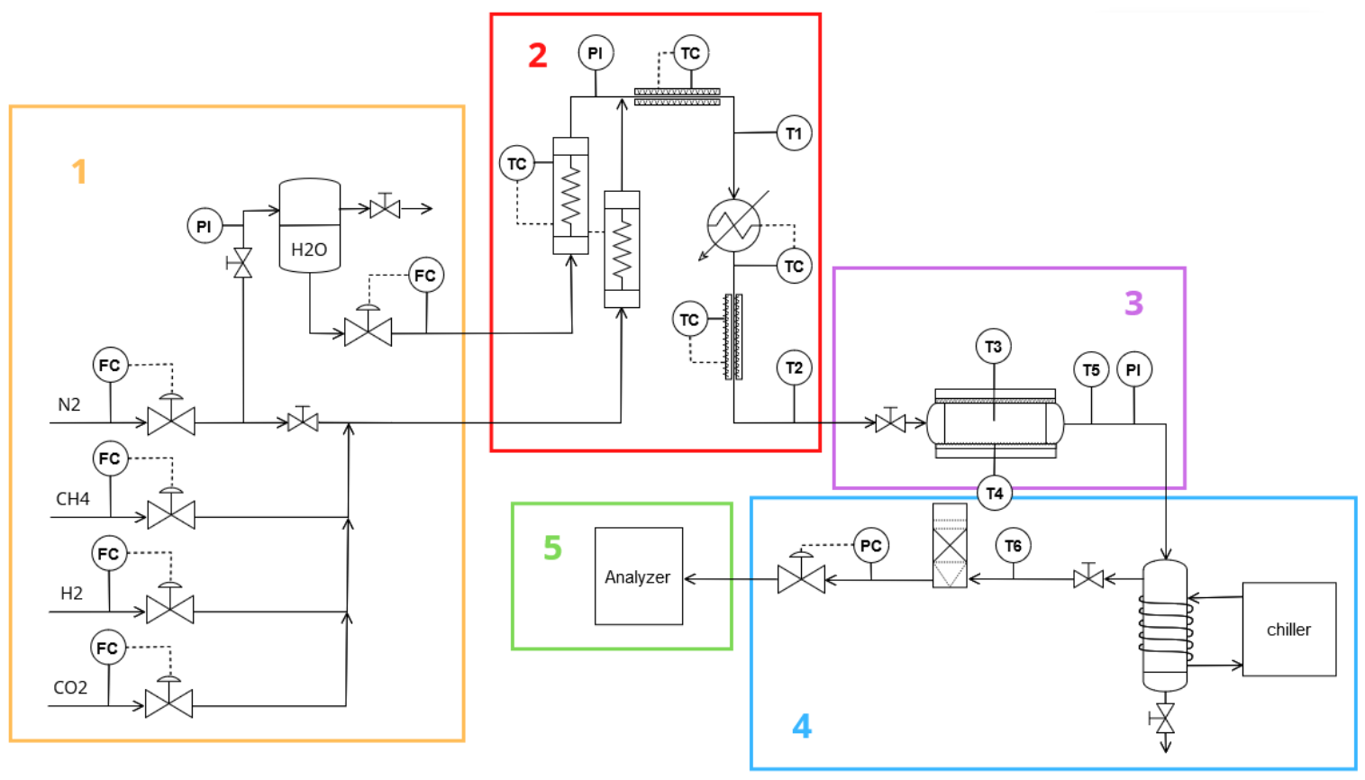
For the experimental tests, three catalyst foams were loaded into a stainless tube reactor. Figure 3 shows the complete experimental setup that consists of five main sections:
  • Inlet flow control section: Digital mass flow controllers (MFCs) regulate the inlet gas streams (N2, CH4, and H2) as well as the water fed to the evaporator. Nitrogen was used for preliminary leak tests, catalyst activation together with hydrogen, and the final purge of the lines. Methane and water were used as reactants for the electrified methane steam-reforming experiments. It is important to note that, in the present study, high-purity CH4 was used as the reactant to represent grid-quality biomethane. This assumption is justified because biomethane produced by commercial upgrading plants and intended for injection into the natural gas grid is composed predominantly of methane, while contaminants are reduced to trace levels to comply with the European specifications for grid injection. Therefore, the use of pure CH4 provides a realistic approximation of the composition of upgraded biomethane for the catalytic performance evaluation conducted in this work.
  • The heating section includes the steam generator, gas preheating unit, and mixing/superheating zone. All the tubes in this section were kept heated with electrical wires and insulated. The steam generator and gas preheating units operate at 300 °C, while the mixing/superheating zone operates at 600 °C. The inlet temperature to the superheater is monitored by the thermocouple (Type K) T1, while the thermocouple T2 measures the temperature of the gas entering the reactor, which is required to be above 300 °C to ensure catalyst activation.
  • The reactor consists of a tubular stainless-steel body (inner diameter, 5 cm; length, 8 cm) placed inside an electrically heated furnace with a maximum power of 800 W. Thermocouples T3–T5 monitor the temperature at the reactor inner axial position (T3), the external wall temperature at the same axial position (T4), and the outlet temperature (T5). T3 is also the temperature control thermocouple, regulating the power supplied to the electrical heaters to maintain the reactor temperature at the set-point value of 750 °C.
  • The cooling and water removal section consists of a cold-water trap operated with an external flux of a water–glycol mixture at −4 °C, followed by a fixed-bed silica gel filter to remove any trace of moisture. Thermocouple T6 measures the gas outlet temperature from the cold trap, which should be maintained below 50 °C for proper analyzer operation.
  • The gas analysis section consists of an ABB AO2020 series analyzer, which is used for continuous monitoring of the outlet gas composition.
Figure 3. Scheme of the experimental setup.
Hydrogen 07 00111 g003

2.3. Experimental Procedure

Prior to the reforming tests, the catalyst was activated under a reducing environment consisting of 10 vol% H2 and 90 vol% N2 at 850 °C for 3 h. Steam-reforming experiments were then carried out at 750 °C and 1 atm, since biomethane is usually available at near-atmospheric pressures. The reaction is globally endothermic, and it occurs with an increase in the number of moles. Consequently, the low-pressure condition shifts the equilibrium toward the products, according to Le Chatelier’s principle. Therefore, since the experiments were carried out at atmospheric pressure, the reaction temperature could be fixed at 750 °C, which is enough to reach an almost complete methane conversion at equilibrium. The steam-to-carbon ratio (S/C) was fixed at 3. Methane was used as a model compound representative of upgraded biomethane, as biomethane typically consists of high-purity methane (>99.8%) after upgrading to meet grid injection specifications. The potential effects of residual CO2 and trace contaminants were not considered in the present study. The gas hourly space velocity (GHSV), calculated as reported in Equation (3), was varied between 2460 and 7380 h−1 to investigate the effect of gas residence time on reactor and catalyst performances:
G H S V = F g a s i n V c a t
where F g a s i n is the total inlet gas flow rate (NmL/h), and V c a t is the total volume of the catalytic foams loaded in the reactor (mL). Each test was conducted in steady-state conditions.
The catalyst performance was evaluated using three parameters: the methane conversion ( X C H 4 ), the hydrogen yield ( Y H 2 ), and the specific energy consumption (SEC), defined as Equations (4)–(6), respectively:
X C H 4 = ( F C H 4 i n −   F C H 4 o u t ) F C H 4 i n
Y H 2 = F H 2 4 · ( F C H 4 i n − F C H 4 o u t )
S E C = Q e l · η V H 2 , p r o d
In Equations (4) and (5), F H 2 is the molar flow rate of hydrogen produced, while F C H 4 i n and F C H 4 o u t are the inlet and outlet molar flow rates of methane, respectively. In Equation (6) Q e l is the electrical energy supplied to the reactor (kWh), recorded during the experimental campaign by the electric steam supplier; η is the electrical efficiency factor; and V H 2 , p r o d is the volume of hydrogen produced under normal conditions (Nm3). The electrical efficiency factor ( η ) was obtained from Equation (7):
η = H ˙ o u t − H ˙ i n P e l
where H ˙ o u t and H ˙ i n are the total enthalpy flow rates of the outlet and inlet streams of the reactor, respectively, and P e l is the electrical power supplied to the reactor. The reported efficiency refers only to the reactor and does not include the power consumption of the steam generator, gas preheaters, heated transfer lines, cooling system, or other auxiliary units of the lab setup.
The enthalpy flow rate was calculated as Equation (8):
H ˙ = ∑ i F i · H f , i 0 + ∫ T r e f T c p , i · d T
F i is the molar flow rate of species i ; H f , i 0 is the standard enthalpy of formation; c p , i is the molar heat capacity at constant pressure; and T r e f is the reference temperature (273.15 K).
Another important parameter with which to assess the reactor performance is the thermal efficiency ( η t h ), defined by Equation (9):
η t h = F H 2 o u t · L H V H 2 + F C O o u t · L H V C O + F C H 4 o u t · L H V C H 4 η · P e l + F C H 4 i n · L H V C H 4
where F H 2 o u t and F C O o u t are the molar flow rates of hydrogen and carbon monoxide in the outlet stream, respectively; F C H 4 i n is the molar flow rate of methane fed to the reactor; and L H V H 2 , L H V C O , and L H V C H 4 are the lower heating values of hydrogen, carbon monoxide, and methane, respectively.

2.4. X-Ray Diffraction (XRD) of the Catalyst

X-ray diffraction (XRD) analyses were performed using a Rigaku SmartLab diffractometer to investigate the structural and mineralogical properties of powdered catalytic samples. The analysis was carried out on three samples of the catalyst: (1) a fresh Ce_Ni catalyst; (2) a fresh Ce/Zr_Ni catalyst; and (3) a spent Ce/Zr_Ni catalyst after the experiments.
Before XRD analysis, the catalytic material was mechanically removed from the corresponding washcoated structured catalysts in the form of macroparticles. The collected material was then mechanically milled to obtain a homogeneous powder. After grinding, the powders were dried at 50 °C to remove adsorbed moisture and minimize possible interference during the measurement. The dried samples were subsequently deposited onto an XRD sample holder, obtaining a thin, compact, and flat layer. Particular attention was paid to reducing preferential orientation effects and surface inhomogeneities, which could affect the relative intensity of diffraction peaks.
The measurements were performed in conventional powder diffraction mode using Cu Kα radiation (λ = 1.5406 Å). Data were collected in θ–2θ geometry over a 2θ range of 10–90°, allowing the identification of the main reflections associated with the silicon carbide support and the crystalline phases present in the washcoat, including cerium oxide, cerium–zirconium oxide, nickel-containing species, and possible phases formed after catalyst operation. The diffraction patterns were collected at room temperature using constant acquisition parameters for all samples to allow direct comparison between the obtained profiles. A typical step size of 0.01° 2θ and a scanning rate of 3° min−1 were used as a compromise between resolution, signal intensity, and acquisition time.
The XRD patterns were analyzed by comparing the experimental peak positions and relative intensities with crystallographic reference data available in standard databases. The comparison among the three samples was performed to identify the main crystalline phases, verify the presence of dispersed Ni and oxide promoters, evaluate the crystalline nature of nickel-containing species, and investigate possible structural modifications induced by catalyst operation.

3. Results and Discussion

3.1. ESMR Experimental Tests

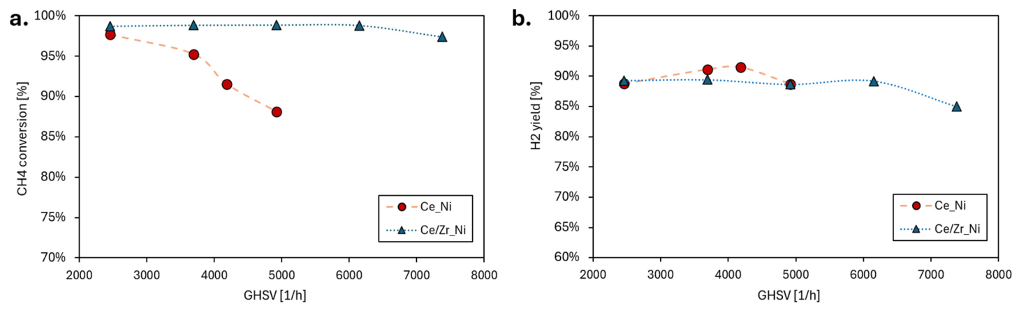
The following figures report the experimental results in terms of methane conversion (Figure 4a) and hydrogen yield (Figure 4b) as a function of GHSV for the two catalyst formulations tested.
As shown in Figure 4a, the Ce/Zr_Ni catalyst maintained a methane conversion close to equilibrium ( X C H 4 e q = 100 % at 750 °C, P = 1 atm, S/C = 3) up to a GHSV of 7380 h−1. In contrast, for the Ce_Ni catalyst, methane conversion decreased to 88% at a GHSV of 4920 h−1. As reported in Figure 4b, both catalysts achieved a hydrogen yield of approximately 90% over the GHSV range investigated. Since Ce_Ni was not tested at higher GHSV values, its behavior under more severe space velocity conditions cannot be directly assessed. The catalyst synthesized using the same methodology was extensively characterized by SEM-EDS analyses [36]. These studies confirmed the homogeneous distribution of Ni and promoter species throughout the washcoat layer. Furthermore, BET surface area measurements showed that the deposition of the washcoat increased the specific surface area (SSA) from approximately 0.8 m2 g−1 to 19 m2 g−1, while the corresponding adsorption–desorption isotherms confirmed the mesoporous nature of the washcoat, which minimizes diffusional resistance [32,36,37]. These structural properties provide a reasonable explanation for the catalytic performance observed in the present study, demonstrating that the catalyst remains effective even under high gas GHSV conditions despite the high void fraction of the support. Intraparticle diffusion is confined to the washcoat and does not occur within the SiC substrate, which has negligible accessible porosity [37]. In addition, the washcoat thickness is only approximately 20–40 μm, providing a very short characteristic diffusion length [38]. Such thin catalytic coatings are well known to substantially reduce internal diffusion resistance compared with conventional pellet catalysts, in which diffusion occurs over characteristic lengths of the order of millimeters. Therefore, internal mass-transfer limitations are expected to be minimal under the investigated conditions [39].
The catalyst containing zirconia showed superior performance, maintaining equilibrium even at high GHSV values, which confirms the higher catalytic activity of the Ce/Zr system. Zirconia, in fact, improves oxygen mobility and reduces internal diffusion limitations within the washcoat layer. This behavior is consistent with the power demand of the reactor: for the Ce_Ni catalyst, power ranged from 392 to 432 W (for GHSV between 2460 and 4920 h−1), while for the Ce/Zr_Ni catalyst, power ranged from 352 to 448 W (for GHSV between 2460 and 7380 h−1), corresponding to a 6–10% lower energy demand compared to the zirconia-free catalyst. The lower electrical power required by the Ce/Zr_Ni catalyst to maintain the reaction temperature may be related to the enhanced redox properties of the mixed oxide support. The incorporation of Zr promotes oxygen vacancy formation and oxygen mobility, improving the Ni–support interaction and facilitating the activation of reactants. Therefore, the same catalytic performance can be achieved with reduced external heat input [34,35,40].
The electrical efficiency factor of the experimental setup was obtained from Equation (7) and was considered η = 0.493. This efficiency accounts for the energy losses through the reactor insulation, which are significant in lab-scale systems. Therefore, the input power was first corrected using electrical efficiency to consider only the power effectively delivered to the reaction. Subsequently, to provide a more realistic estimation of catalyst performance upon scale-up, the energy consumption for the following evaluations was recalculated using an electrical efficiency of η = 0.9, representative of typical industrial electric reactors [41,42,43].
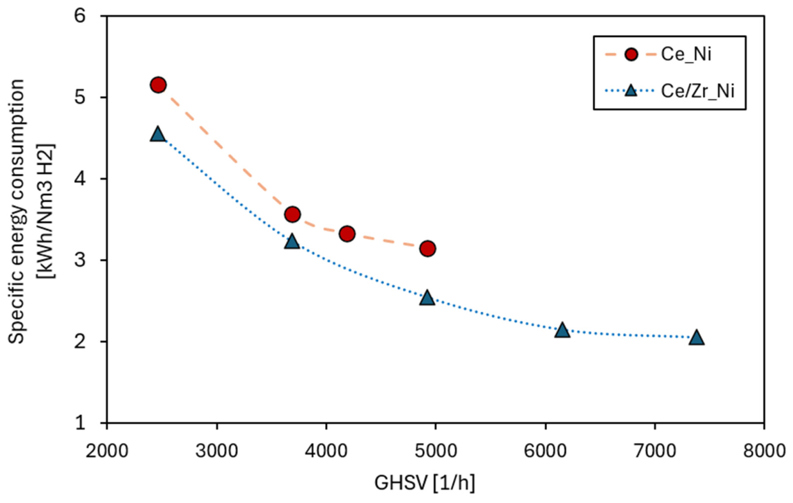
Figure 5 shows the estimated specific energy consumption per Nm3 of hydrogen produced as a function of GHSV for the two catalysts under scaled-up electrical efficiency assumptions. For the Ce_Ni catalyst, the specific energy consumption reaches a minimum value of 3.15 kWh/Nm3 H2 at a GHSV of 4920 h−1, while for the zirconia-containing catalyst, the minimum specific energy consumption is 2.06 kWh/Nm3 H2 at a GHSV of 7380 h−1. This value represents a promising result, as it is consistent with competitive values reported in the literature for similar conditions in eSMR applications [44]. It is important to notice that the electrical power used for the SEC calculation was determined from the measured voltage and current of the transformer supplying the reactor furnace. Therefore, the reported power refers only to the reactor and does not include the power consumption of the steam generator, gas preheaters, heated transfer lines, cooling system, or other auxiliary units. A complete assessment of the overall electrical consumption of the laboratory unit would require the measurement of additional auxiliary loads, which were not included in the present SEC calculation.
When comparing the thermal efficiency ( η t h ), calculated according to Equation (9), a value of 57% was obtained at a GHSV of 4920 h−1 for the Ce_Ni catalyst, whereas the Ce/Zr_Ni catalyst achieved a thermal efficiency of 67% under the same operating conditions. Furthermore, increasing the GHSV to 7380 h−1 resulted in a thermal efficiency of 75% for the Ce/Zr_Ni catalyst. In addition, radial thermal gradients within the reactor remained below 10 °C, and no microscopic signs of coke formation were observed even after several hours of operation. For comparison, conventional fired steam reformers employing packed-bed alumina pellet catalysts typically exhibit radial temperature differences in the order of 60 °C due to the limited effective thermal conductivity of the packed bed and the inefficient heat transfer from the external furnace through radiation [45]. It should be noted that this comparison involves a laboratory-scale electrically heated reactor and industrial-scale furnace tubes with substantially different geometries and dimensions. Therefore, the comparison should be regarded as qualitative, highlighting the potential of electrified SiC foam reactors to improve temperature uniformity rather than representing a direct quantitative comparison. These results strongly support the hypothesis that improving heat transport within the catalytic bed using thermally conductive structures such as SiC significantly enhances catalytic activity. For comparison, the main results of the two catalysts at GHSV 4920 h−1 are reported in Table 2.
The tested GHSV may appear lower than those typically adopted in conventional reformers; however, a direct comparison is challenging due to the significant differences between structured OCF catalysts and commercial pellet-based catalyst beds. The lower GHSV is mainly attributed to the high void fraction of the OCF (0.85 compared with 0.3–0.4 for packed pellet beds), which results in a lower catalyst volume per reactor volume. In fact, when comparing the catalytic loading, the reactor achieved equilibrium despite the significantly lower amount of catalyst employed; the bulk density of the foams was approximately 639 kgcat/m3 (referred to the empty reactor volume), while the commercial nickel catalyst, supported on alumina pellets, is typically in the range between 800 and 1300 kgcat/m3 [10,46]. This enables the use of a lower catalyst amount within the same reactor volume, potentially allowing the development of more compact and intensified reformer designs. Additionally, compared to packed beds with pellets, the highly porous monolithic support reduces pressure drops, which is an important feature when a low-pressure gas like biomethane is used as feedstock. Therefore, structured catalytic systems could overcome the strong economies of scale that have traditionally favored large-scale conventional reformers. As a result, these intensified reactors may become economically attractive for decentralized hydrogen production from sustainable feedstocks, such as biomethane, which are typically available at smaller production scales compared with natural gas.

3.2. XRD Analyses

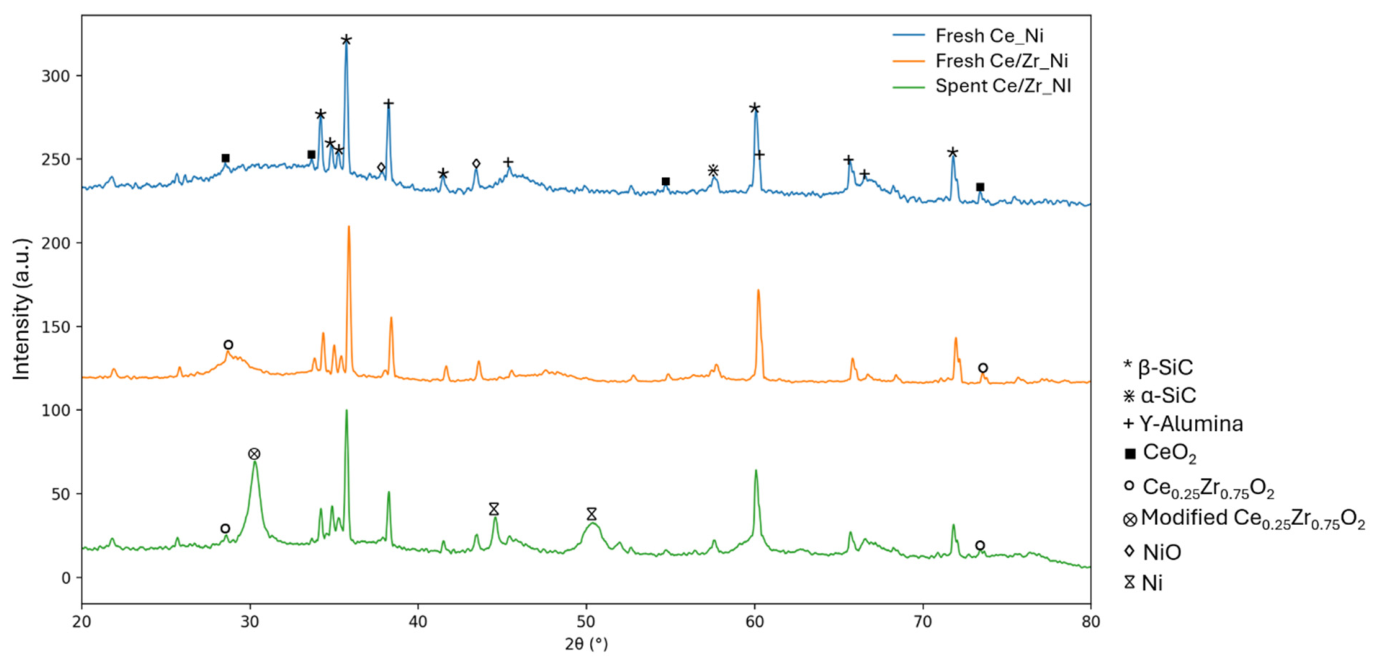
XRD analyses were performed on both fresh and spent catalysts. These analyses provide information on the crystalline phases and structural features of the materials and allow the evaluation of the successful outcome of the washcoating procedure. Furthermore, the characterization of the spent catalysts enables the identification of possible structural modifications induced by prolonged exposure to high temperatures and reaction conditions. The XRD patterns are reported in Figure 6.
The main diffraction peaks observed in the range between 33° and 36° and the reflection at approximately 60.1° are attributed to β-SiC, which represents the main component of the support structure. Additionally, a diffraction peak at around 37.5° can be assigned to α-SiC, possibly related to structural defects or local rearrangements commonly observed in commercial OCF supports.
Regarding the Ce_Ni catalyst, the characteristic reflections of the fluorite CeO2 structure are observed at 28.5° (111), 33.1° (200), 56.3° (311), 59.1° (222), and 76.7° (331). Similar reflections are also detected for the Ce/Zr_Ni catalyst, with a slight shift toward higher diffraction angles, suggesting the incorporation of Zr4+ into the CeO2 lattice and the formation of a Ce–Zr–O fluorite-type structure [47]. The diffraction peaks associated with NiO are also identified at 37.2° (111) and 43.3° (200), confirming the presence of oxidized nickel species in the fresh catalysts.
After catalytic testing, the diffraction features associated with SiC and γ-Al2O3 remain essentially unchanged, indicating the structural stability of the support under reforming conditions. Moreover, no significant variation is observed in the 20–30° region, particularly around 26°, which is commonly associated with the (002) reflection of graphitic carbon. This confirms the absence of detectable crystalline carbon deposits after prolonged catalytic operation. However, the possible presence of amorphous carbon deposits cannot be excluded based solely on XRD analysis and would require complementary characterization techniques, such as RAMAN. Additional diffraction peaks observed in the spent catalysts at approximately 44.5° (111), 51.8° (200), and 76.4° (220) are attributed to metallic Ni. These reflections confirm the effective reduction of oxidized nickel species after the reduction procedure and the formation of metallic Ni, which represents the active phase for the reforming reaction.
Finally, the appearance of an additional diffraction peak at 2θ ≈ 30.3° in the spent catalyst indicates that the Ce0.25Zr0.75O2 phase potentially underwent structural modifications during catalytic operation, as suggested in the literature [48,49]. This reflection can be associated with the formation of a Zr-enriched fluorite-type Ce–Zr–O structure resulting from lattice contraction, which is induced by the incorporation of Zr4+ into the CeO2 framework [49]. The shift/reorganization of the mixed oxide structure observed may also be related to the generation of oxygen vacancies and the partial reduction of Ce4+ to Ce3+ under reaction conditions [48]. These potential structural changes emphasize the dynamic role of the Ce0.25Zr0.75O2 phase as a redox-active precursor during the reaction. In fact, oxygen mobility and reversible Ce4+/Ce3+ transformations promote reactant activation and carbonaceous species removal. Therefore, the modified diffraction pattern of the spent catalyst indicates the evolution of the Ce–Zr–O phase under catalytic conditions.

4. Conclusions

This work focused on the development of optimized structured catalysts for electrified steam methane reforming (eSMR) operating under conditions representative of biomethane-fed systems. Two structured catalysts were prepared on SiC OCFs by washcoating: 30 wt.% Al2O3_30 wt.% CeO2_20 wt.%Ni and 30 wt.% Al2O3_30 wt.% Ce0.25Zr0.75O2_20 wt.%Ni formulations; these catalytic systems were experimentally evaluated in a laboratory-scale electrically heated reformer, where heat was indirectly supplied through an external resistance for the Joule-heating system. The high thermal conductivity of the SiC structured support ensured efficient heat transfer throughout the reactor, limiting radial temperature gradients to below 10 °C and promoting a more homogeneous catalyst temperature. The incorporation of Zr as a promoter further improved the catalytic performance, allowing equilibrium methane conversion to be maintained at GHSV values above 7000 h−1 while reducing the specific electrical energy consumption by 6–10% compared with the CeO2-based catalyst. The beneficial role of the Ce0.25Zr0.75O2 was also supported by the XRD characterization of the spent catalyst, as it shows a modified Ce–Zr–O diffraction, suggesting that the mixed oxide potentially underwent structural evolution under reaction conditions. Such behavior is consistent with the well-known redox nature of Ce–Zr oxides, the high oxygen mobility and reversible structural rearrangements of which promote the activation of reactants and contribute to preserving the catalytic activity by enhancing oxygen transfer at the catalyst surface. Future work will include a more comprehensive physicochemical characterization of the catalysts to further elucidate the role of Ce and Ce–Zr promoters. In particular, Raman spectroscopy will be employed to investigate carbon deposition and coke structure after reactions, while X-ray photoelectron spectroscopy (XPS) will be used to examine the surface chemical states of the active species and promoters. The measured specific electrical energy consumption was in good agreement with values reported in the literature for comparable electrified reforming systems. The best performance was achieved with the Ce/Zr_Ni catalyst at a GHSV of 7380 h−1, corresponding to a specific energy consumption of 2.06 kWh Nm−3 H2 projected for industrial-scale efficiency of 0.9.
Overall, the obtained results demonstrate that the combination of highly conductive SiC structured supports with Ce–Zr-promoted Ni catalysts represents an effective strategy for improving both the catalytic and thermal performance of electrified steam methane reforming. The power-to-chemical energy conversion factor of the reactor can potentially be increased to η t h > 0.75 after scale-up, which represents a relevant efficiency target when compared with other power-to-fuel technologies such as water electrolysis. Future developments should include extended time-on-stream stability tests to evaluate the long-term durability of the catalyst under continuous operating conditions together with a more comprehensive physicochemical characterization of the catalyst using complementary techniques (e.g., BET surface area analysis, SEM-EDS, and TEM). Beyond the improved catalytic activity and reduced electrical energy demand, the proposed configuration is particularly well suited for decentralized and small-scale hydrogen production from biomethane, where high energy efficiency, compact reactor design, low-pressure drops and operational flexibility are essential requirements. This makes the electrification of industrial chemical processes a promising solution for contributing to the transition towards the production of low-carbon hydrogen.

Author Contributions

Conceptualization, D.D.C. and L.D.P.; methodology, D.D.C. and L.D.P.; validation, D.D.C. and L.D.P.; investigation, D.D.C., L.D.P. and P.C.; data curation, D.D.C., L.D.P. and P.C.; writing—original draft preparation, D.D.C. and L.D.P.; writing—review and editing, F.S., P.C., A.G. and V.P.; visualization, D.D.C. and L.D.P.; supervision, A.G. and V.P.; funding acquisition, A.G. All authors have read and agreed to the published version of the manuscript.

Funding

This research was funded by Italian Ministry of Environment and Energy Security: I83C22001170006; Ministry of Universities and Research: I53C22001450006.

Institutional Review Board Statement

The study did not require ethical approval.

Informed Consent Statement

Not applicable.

Data Availability Statement

Data are available upon request.

Acknowledgments

This research was funded by the European Union—NextGenerationEU from the Italian Ministry of Environment and Energy Security, POR H2 AdP MEES/ENEA with involvement of CNR and RSE, PNRR—Mission 2, Component 2, Investment 3.5 “Ricerca e sviluppo sull’idrogeno”, CUP: I83C22001170006.; This work has also been supported by the National Recovery and Resilience Plan (NRRP), Mission 4 Component 2 Investment 1.3—Call for tender No. 1561 of 10 November 2022 of Ministero dell’Università e della Ricerca (MUR); the European Union—NextGenerationEU. Award Number: Project code PE0000021, Concession Decree No. 1561 of 10 November 2022 adopted by Ministero dell’Università e della Ricerca (MUR), CUP I53C22001450006, according to attachment E of Decree No. 1561/2022, Project title “Network 4 Energy Sustainable Transition—NEST”.

Conflicts of Interest

The authors declare no conflict of interest.

References

  1. International Energy Agency. Net Zero by 2050—A Roadmap for the Global Energy Sector. Available online: https://www.iea.org/reports/net-zero-by-2050 (accessed on 1 June 2026).
  2. Meloni, E.; Iervolino, G.; Ruocco, C.; Renda, S.; Festa, G.; Martino, M.; Palma, V. Electrified Hydrogen Production from Methane for PEM Fuel Cells Feeding: A Review. Energies 2022, 15, 3588. [Google Scholar] [CrossRef] [Scilit]
  3. Soltani, R.; Rosen, M.A.; Dincer, I. Assessment of CO2 capture options from various points in steam methane reforming for hydrogen production. Int. J. Hydrogen Energy 2014, 39, 20266–20275. [Google Scholar] [CrossRef] [Scilit]
  4. Hoang, A.T.; Pandey, A.; De Osés, F.J.M.; Chen, W.-H.; Said, Z.; Ng, K.H.; Ağbulut, Ü.; Tarełko, W.; Ölçer, A.I.; Nguyen, X.P. Technological solutions for boosting hydrogen role in decarbonization strategies and net-zero goals of world shipping: Challenges and perspectives. Renew. Sustain. Energy Rev. 2023, 188, 113790. [Google Scholar] [CrossRef] [Scilit]
  5. Megía, P.J.; Vizcaíno, A.J.; Calles, J.A.; Carrero, A. Hydrogen Production Technologies: From Fossil Fuels toward Renewable Sources. A Mini Review. Energy Fuels 2021, 35, 16403–16415. [Google Scholar] [CrossRef] [Scilit]
  6. Tiwari, A. The Emerging Global Trends in Hydrogen Energy Research for Achieving the Net Zero Goals. Adv. Mater. Lett. 2021, 12, 1–5. [Google Scholar] [CrossRef] [Scilit]
  7. Ewan, B.; Allen, R. A figure of merit assessment of the routes to hydrogen. Int. J. Hydrogen Energy 2005, 30, 809–819. [Google Scholar] [CrossRef] [Scilit]
  8. Wismann, S.T.; Engbæk, J.S.; Vendelbo, S.B.; Bendixen, F.B.; Eriksen, W.L.; Aasberg-Petersen, K.; Frandsen, C.; Chorkendorff, I.; Mortensen, P.M. Electrified methane reforming: A compact approach to greener industrial hydrogen production. Science 2019, 364, 756–759. [Google Scholar] [CrossRef] [Scilit] [PubMed]
  9. International Energy Agency. Global Hydrogen Review 2025. Available online: https://www.iea.org/reports/global-hydrogen-review-2025 (accessed on 3 June 2026).
  10. Rostrup-Nielsen, J.; Christiansen, L.J. Concepts in Syngas Manufacture; Imperial College Press: London, UK, 2011; Volume 10. [Google Scholar]
  11. Kumar, A.; Baldea, M.; Edgar, T.F. A physics-based model for industrial steam-methane reformer optimization with non-uniform temperature field. Comput. Chem. Eng. 2017, 105, 224–236. [Google Scholar] [CrossRef] [Scilit]
  12. Do, H.H.; Tran, N.T.; Van Tran, V. Insights into the state-of-the-art developments in defect engineering on molybdenum compounds for electrochemical hydrogen evolution reaction. Mater. Today Energy 2024, 45, 101695. [Google Scholar] [CrossRef] [Scilit]
  13. Mohan, V.K.; Srivastav, A.; Güell, F.; John, T.T. pH-controlled synthesis of ZnO nanoflowers: A correlation study among the optoelectronic properties and improved photodegradation efficiency. J. Alloys Compd. 2024, 976, 172993. [Google Scholar] [CrossRef] [Scilit]
  14. Truong, H.B.; Tran, N.T.; Do, H.H. Recent advancements and perspectives of hydrogen evolution reaction electrocatalysts based on molybdenum phosphides. Int. J. Hydrogen Energy 2024, 80, 696–711. [Google Scholar] [CrossRef] [Scilit]
  15. Giaconia, A.; Iaquaniello, G.; Morico, B.; Salladini, A.; Palo, E. Techno-economic assessment of solar steam reforming of methane in a membrane reactor using molten salts as heat transfer fluid. Int. J. Hydrogen Energy 2021, 46, 35172–35188. [Google Scholar] [CrossRef] [Scilit]
  16. De Cata, D.; Mazzeo, L.; Piemonte, V.; Giaconia, A. Electrified steam methane reforming as efficient pathway for sustainable hydrogen production and industrial decarbonization: A critical review. Int. J. Hydrogen Energy 2025, 105, 31–44. [Google Scholar] [CrossRef] [Scilit]
  17. International Renewable Energy Agency. Green Hydrogen Cost Reduction: Scaling up Electrolysers to Meet the 1.5 °C Climate Goal; International Renewable Energy Agency: Abu Dhabi, United Arab Emirates, 2020. [Google Scholar]
  18. Almind, M.R.; Vendelbo, S.B.; Hansen, M.F.; Vinum, M.G.; Frandsen, C.; Mortensen, P.M.; Engbæk, J.S. Improving performance of induction-heated steam methane reforming. Catal. Today 2020, 342, 13–20. [Google Scholar] [CrossRef] [Scilit]
  19. Govender, S.; Friedrich, H.B. Monoliths: A Review of the Basics, Preparation Methods and Their Relevance to Oxidation. Catalysts 2017, 7, 62. [Google Scholar] [CrossRef] [Scilit]
  20. Moriggi, S.; De Cata, D.; Bove, D.; Bosio, B. Mathematical modeling of an electrified methane steam reforming unit for maritime sector decarbonization via MCFC. Int. J. Thermofluids 2025, 27, 101251. [Google Scholar] [CrossRef] [Scilit]
  21. Ponikvar, Ž.; Likozar, B.; Gyergyek, S. Electrification of Catalytic Ammonia Production and Decomposition Reactions: From Resistance, Induction, and Dielectric Reactor Heating to Electrolysis. ACS Appl. Energy Mater. 2022, 5, 5457–5472. [Google Scholar] [CrossRef] [Scilit]
  22. Cao, G.; Handler, R.M.; Luyben, W.L.; Xiao, Y.; Chen, C.-H.; Baltrusaitis, J. CO2 conversion to syngas via electrification of endothermal reactors: Process design and environmental impact analysis. Energy Convers. Manag. 2022, 265, 115763. [Google Scholar] [CrossRef] [Scilit]
  23. Zheng, L.; Ambrosetti, M.; Tronconi, E. Joule-Heated Catalytic Reactors toward Decarbonization and Process Intensification: A Review. ACS Eng. Au 2024, 4, 4–21. [Google Scholar] [CrossRef] [Scilit]
  24. Meloni, E.; Martino, M.; Ricca, A.; Palma, V. Ultracompact methane steam reforming reactor based on microwaves susceptible structured catalysts for distributed hydrogen production. Int. J. Hydrogen Energy 2021, 46, 13729–13747. [Google Scholar] [CrossRef] [Scilit]
  25. Ambrosetti, M.; Beretta, A.; Groppi, G.; Tronconi, E. A Numerical Investigation of Electrically-Heated Methane Steam Reforming Over Structured Catalysts. Front. Chem. Eng. 2021, 3, 747636. [Google Scholar] [CrossRef] [Scilit]
  26. Nelson, A.E. Fundamentals of Industrial Catalytic Processes, 2nd Edition. C. H. Bartholomew and Robert J. Farrauto John Wiley and Sons, Hoboken, NJ, 966 pp., 2006. Can. J. Chem. Eng. 2007, 85, 127–128. [Google Scholar] [CrossRef] [Scilit]
  27. Morales-Cano, F.; Lundegaard, L.F.; Tiruvalam, R.R.; Falsig, H.; Skjøth-Rasmussen, M.S. Improving the sintering resistance of Ni/Al2O3 steam-reforming catalysts by promotion with noble metals. Appl. Catal. A Gen. 2015, 498, 117–125. [Google Scholar] [CrossRef] [Scilit]
  28. Ayodele, B.V.; Khan, M.R.; Lam, S.S.; Cheng, C.K. Production of CO-rich hydrogen from methane dry reforming over lanthania-supported cobalt catalyst: Kinetic and mechanistic studies. Int. J. Hydrogen Energy 2016, 41, 4603–4615. [Google Scholar] [CrossRef] [Scilit]
  29. Zheng, L.; Ambrosetti, M.; Marangoni, D.; Beretta, A.; Groppi, G.; Tronconi, E. Electrified methane steam reforming on a washcoated SiSiC foam for low-carbon hydrogen production. AIChE J. 2023, 69, 17620. [Google Scholar] [CrossRef] [Scilit] [PubMed]
  30. Zeppieri, M.; Villa, P.L.; Verdone, N.; Scarsella, M.; De Filippis, P. Kinetic of methane steam reforming reaction over nickel- and rhodium-based catalysts. Appl. Catal. A Gen. 2010, 387, 147–154. [Google Scholar] [CrossRef] [Scilit]
  31. Sekine, Y.; Haraguchi, M.; Matsukata, M.; Kikuchi, E. Low temperature steam reforming of methane over metal catalyst supported on CexZr1−xO2 in an electric field. Catal. Today 2011, 171, 116–125. [Google Scholar] [CrossRef] [Scilit]
  32. Meloni, E.; Iervolino, G.; Palma, V. Highly-efficient hydrogen production through the electrification of OB-SiC nickel structured catalyst: Methane steam reforming and ammonia cracking as case studies. Int. J. Hydrogen Energy 2024, 65, 42–49. [Google Scholar] [CrossRef] [Scilit]
  33. Song, H.; Ozkan, U. Ethanol steam reforming over Co-based catalysts: Role of oxygen mobility. J. Catal. 2009, 261, 66–74. [Google Scholar] [CrossRef] [Scilit]
  34. de Abreu, A.J.; Lucrédio, A.F.; Assaf, E.M. Ni catalyst on mixed support of CeO2–ZrO2 and Al2O3: Effect of composition of CeO2–ZrO2 solid solution on the methane steam reforming reaction. Fuel Process. Technol. 2012, 102, 140–145. [Google Scholar] [CrossRef] [Scilit]
  35. Di Monte, R.; Kašpar, J. Heterogeneous environmental catalysis—A gentle art: CeO2–ZrO2 mixed oxides as a case history. Catal. Today 2005, 100, 27–35. [Google Scholar] [CrossRef] [Scilit]
  36. Meloni, E.; Saraceno, E.; Martino, M.; Corrado, A.; Iervolino, G.; Palma, V. SiC-based structured catalysts for a high-efficiency electrified dry reforming of methane. Renew. Energy 2023, 211, 336–346. [Google Scholar] [CrossRef] [Scilit]
  37. von Rickenbach, J.; Lucci, F.; Narayanan, C.; Eggenschwiler, P.D.; Poulikakos, D. Effect of washcoat diffusion resistance in foam based catalytic reactors. Chem. Eng. J. 2015, 276, 388–397. [Google Scholar] [CrossRef] [Scilit]
  38. Meloni, E.; Martino, M.; Palma, V. Microwave assisted steam reforming in a high efficiency catalytic reactor. Renew. Energy 2022, 197, 893–901. [Google Scholar] [CrossRef] [Scilit]
  39. Cornejo, I.; Hayes, R.E. A Review of the Critical Aspects in the Multi-Scale Modelling of Structured Catalytic Reactors. Catalysts 2021, 11, 89. [Google Scholar] [CrossRef] [Scilit]
  40. Pereira, V.G.F.; Serrano-Lotina, A.; Portela, R.; Bañares, M.A.; Rodrigues, C.P.; Toniolo, F.S. Ni/Al2O3 promoted by CeO2, CeO2-La2O3, and CeO2-ZrO2 supported on cordierite monoliths for methane steam reforming. Catal. Today 2025, 445, 115107. [Google Scholar] [CrossRef] [Scilit]
  41. Maporti, D.; Guffanti, S.; Galli, F.; Mocellin, P.; Pauletto, G. Towards sustainable hydrogen production: Integrating electrified and convective steam reformer with carbon capture and storage. Chem. Eng. J. 2024, 499, 156357. [Google Scholar] [CrossRef] [Scilit]
  42. Song, H.; Liu, Y.; Bian, H.; Shen, M.; Lin, X. Energy, environment, and economic analyses on a novel hydrogen production method by electrified steam methane reforming with renewable energy accommodation. Energy Convers. Manag. 2022, 258, 115513. [Google Scholar] [CrossRef] [Scilit]
  43. Natrella, G.; Borgogna, A.; Salladini, A.; Iaquaniello, G. How to give a renewed chance to natural gas as feed for the production of hydrogen: Electric MSR coupled with CO2 mineralization. Clean. Eng. Technol. 2021, 5, 100280. [Google Scholar] [CrossRef] [Scilit]
  44. Zheng, L.; Ambrosetti, M.; Zaio, F.; Beretta, A.; Groppi, G.; Tronconi, E. Direct electrification of Rh/Al2O3 washcoated SiSiC foams for methane steam reforming: An experimental and modelling study. Int. J. Hydrogen Energy 2023, 48, 14681–14696. [Google Scholar] [CrossRef] [Scilit]
  45. Kuncharam, B.V.R.; Dixon, A.G. Multi-scale two-dimensional packed bed reactor model for industrial steam methane reforming. Fuel Process. Technol. 2020, 200, 106314. [Google Scholar] [CrossRef] [Scilit]
  46. Johnson Matthey. JM Steam Reforming Catalysts Product Brochure; Johnson Matthey: London, UK, 2019. [Google Scholar]
  47. Pengpanich, S.; Meeyoo, V.; Rirksomboon, T. Methane partial oxidation over Ni/CeO2-ZrO2 mixed oxide solid solution catalysts. Catal. Today 2004, 93–95, 95–105. [Google Scholar] [CrossRef] [Scilit]
  48. Kuhn, M.; Bishop, S.R.; Rupp, J.L.M.; Tuller, H.L. Structural characterization and oxygen nonstoichiometry of ceria-zirconia (Ce1−xZrxO2−δ) solid solutions. Acta Mater. 2013, 61, 4277–4288. [Google Scholar] [CrossRef] [Scilit]
  49. Mamontov, E.; Egami, T.; Brezny, R.; Koranne, M.; Tyagi, S. Lattice Defects and Oxygen Storage Capacity of Nanocrystalline Ceria and Ceria-Zirconia. J. Phys. Chem. B 2000, 104, 11110–11116. [Google Scholar] [CrossRef] [Scilit]
Figure 1. eSMR advances for decarbonization and process intensification compared with conventional fired reformers (based on the concept reported in Reference [23]).
Hydrogen 07 00111 g001
Figure 2. Structured OCF washcoated catalyst: (a) Ce_Ni and (b) Ce/Zr_Ni.
Hydrogen 07 00111 g002
Figure 4. (a) CH4 conversion as a function of GHSV for the Ce_Ni and Ce/Zr_Ni catalysts. (b) H2 yield as a function of GHSV for the Ce_Ni and Ce/Zr_Ni catalysts. The tests were conducted at T = 750 °C, P = 1 atm, S/C = 3.
Hydrogen 07 00111 g004
Figure 5. Estimated specific energy consumption as a function of GHSV for the Ce_Ni and Ce/Zr_Ni catalysts under scaled-up electrical efficiency assumptions ( η = 0.9). The tests were conducted at T = 750 °C, P = 1 atm, S/C = 3.
Hydrogen 07 00111 g005
Figure 6. XRD analysis of the catalyst before and after the experiments.
Hydrogen 07 00111 g006
Table 1. Representative mass balance of the catalyst formulation.
ComponentMass (g)
SiC foam18.689
Al2O33.925
Ce or Ce–Zr oxide1.682
Ni1.121
Total washcoat (Al2O3 + promoter)5.607
Final catalyst mass25.417
Table 2. Main results of the two tested catalysts at fixed values of GHSV 4920 h−1, T = 750 °C, P = 1 atm, S/C = 3. The reported values are intended for direct comparison between catalyst formulations.
Catalyst X C H 4 Y H 2 Measured Power [W] η t h SEC [kWh/Nm3]
Ce_Ni0.900.894320.573.15
Ce/Zr_Ni0.970.893920.672.55
Disclaimer/Publisher’s Note: The statements, opinions and data contained in all publications are solely those of the individual author(s) and contributor(s) and not of MDPI and/or the editor(s). MDPI and/or the editor(s) disclaim responsibility for any injury to people or property resulting from any ideas, methods, instructions or products referred to in the content.