Article

Experimental Investigation of Destructive and Non-Destructive Properties for Thermosetting and Thermoplastic Polymers

by
Emilios Sideridis
and
Efstathios E. Theotokoglou
*
Laboratory of Strength of Materials, Department of Mechanics, School of Applied Mathematics and Physical Sciences, National Technical University of Athens, Theocaris Building, Iroon Polytechniou 5, Zographou, GR-157 73 Athens, Greece
*
Author to whom correspondence should be addressed.
Eng 2026, 7(8), 417; https://doi.org/10.3390/eng7080417
Submission received: 19 November 2025 / Revised: 1 August 2026 / Accepted: 6 August 2026 / Published: 16 August 2026
(This article belongs to the Section Chemical, Civil and Environmental Engineering)

Abstract

This experimental work aims at the study by non-destructive and destructive testing of the mechanical and acoustical properties of cold-setting epoxy resins plasticized with amounts of plasticizer and of PMMA (Plexiglas), both belonging to the two basic categories (thermosetting and thermoplastics respectively) of polymeric materials, which usually can be modified because of polymerization rate and curing, change in temperature and frequency, by the addition of plasticizers and/or inclusions as well as due to discontinuities (defects, voids and porosity) where stress concentration exists. On the other hand, ultrasound is a mechanical, elastic wave of very high frequency, and can be used for material testing. Using ultrasounds, defects, discontinuities, and damage can be detected, and moduli can be evaluated accurately. It should be noted that the moduli determined in this way are the dynamic moduli and differ from the static ones for any material. Here, the authors focus their study on plasticized epoxy resins and PMMA and apply this NDT method to estimate mechanical properties and correlate the results with those from destructive tests. Finally, the glass-transition temperature of plasticized epoxies was also evaluated from thermal experiments to determine the effect of the plasticizer.

1. Introduction

The study of mechanical properties of polymeric materials often includes two main interrelated aims: the obtention of a sufficient macroscopic delineation of the material behaviour and the search for an elucidation of this behaviour in terms of molecules, comprising, in detail, the chemical components and physical structure. However, it usually seems not easy to rank polymeric systems as material types, either as glassy solids or viscous fluids, because their mechanical properties depend strongly on the testing conditions, the rate of applying the load, temperature, frequency, amount of strain, etc. Thus, polymers may exhibit all characteristics of glassy brittle solids, elastic rubbers, or viscous fluids, depending on the temperature and time scale of measurement. Therefore, a polymer is typically described as a viscoelastic material, a term emphasizing its intermediate behaviour between a viscous fluid and an elastic solid, with dependence on the temperature and frequency.
Since experimental investigation of viscoelasticity in these materials has been extensive, and due to the development of many techniques, to understand viscoelastic behaviour, satisfactorily, it is required to obtain data over a broad range of frequency, time, and temperature [1].
It is known that there has been a rapid increase in the use of various composites in recent years, particularly for modern engineering implementations [2]. Thermoset and thermoplastic polymers are used as matrices for composites [3]. Among polymers, epoxy resins are largely used as matrices. Resins based on diglycidyl ether of bisphenol A (DGEBA) are important due to their use for reinforcement [4], also in electronics [5], coatings [6], and adhesives [7]. The thermomechanical properties, high chemical and corrosion resistance, strong adhesion to various substrates, low shrinkage upon cure, good electrical insulating properties, and ability to be processed under various conditions characterize this type of resin, and thus it attracts high demand. However, high crosslinking during the cure reaction renders them very brittle and less resistant to cracking, and thus, unsuitable for some critical applications [8,9]. In order to face this issue, the resin is enhanced by adding suitable toughening agents that not only reduce brittleness but also improve toughness, impact resistance, ductility, and resistance to crack propagation. However, material strength and stiffness do not often agree with this procedure [10,11].
Several methods have been used for the modification of epoxy resins, to achieve improvement of toughness and, also, a reduction in brittleness [2]. Among these methods are blending with inorganic particles, which can increase resin viscosity and, consequently, cause other problems during infusion and curing; liquid elastomers, which may reduce mechanical properties and thermal stability; thermoplastics; and biodegradable polymers. Consequently, the more convenient method seems to be the incorporation of dispersed polymers in the cured epoxy resin [12,13,14]. An approximation for the amelioration of the elongation properties of epoxy is the modification of the curing agent [15] without degrading its properties [16]. A detailed study on this subject was carried out in Ref. [17], in which the heat resistance, mechanical properties, and toughness of utilized curing products were studied, leading to improved tensile modulus and tensile strength.
It can be noted that among the methods, the use of plasticizers has a significant role. They are materials added to the polymer in order to either facilitate the processability or make the overall material more flexible [2]. Their main use is with thermoplastic materials. The decrease in the transition temperature improves flexibility but preserves mechanical and thermal properties. However, adding plasticizers to epoxies has also been investigated in the past, and this investigation continues today, with plasticizers different from the liquid polysulfide polymer in the DGEBA resin in the present work.
On the other hand, polymethyl methacrylate (PMMA), used in the experiments of this work, is a thermoplastic polymer for modelling the relaxation and plastic flow mechanisms of deformation, and the stress–strain response which characterizes it and relates to its structure [18]. The main reason for choosing this material is that when a wave passes, it presents large changes in its molecule, resulting in a more intense signal than expected due to changes in the dynamic constants.
It is well known that non-destructive techniques (NDT) are extremely wide ranging [visual inspection, radiographic testing, electromagnetic testing, penetrant testing, magnetic particle testing, infrared and thermal testing, acoustic emission testing], resulting in a large amount of literature over the last forty years. Inevitably, within the field of ultrasonic-based non-destructive measurements [19,20,21], there exists, of course, many diverse applications. Some of them are pulse echo, laser-generated ultrasound, acoustic emission, through transmission, guided waves, bulk wave analysis, surface of the polymer or increased flexibility of the overall material, wave analysis, reflection- and transmission-based analysis, point-source point-receiver techniques, air-coupled analysis, elastic constant determination, and defect detection.
Concurrently, it is possible to locate and determine microscopic or macroscopic discontinuities in time, via NDT methods, which are procedures aimed at testing materials to assess their structural integrity. Although the development of these methods has been associated with the detection of flaws and defects in various materials, the real objective of NDT is considered to ensure that they do not exist. It would not be immoderate if we said that there exists a large list of applications for this method. Practically, an inspection of every product, no matter its size, location, and/or material composition, can be performed using one of the existing or developing NDT techniques. Amongst them one may distinguish the ultrasound method.
A direct application of the latter is to evaluate macroscopic defects, as well as indirectly to evaluate microscopic defects. It can be said that this is an appropriate NDT method to determine the mechanical properties of a large category of materials. Ultrasonics can be applied through various methods based on the creation and scientific discovery of mechanical waves that propagate through the objects of study [22]. There is no restriction for either metal or other solids. The utilization of the methods of this test is for material characterization studies based on the principle that the speed of ultrasound waves travelling through a material is a function of its density [23]. An ultrasound wave, when striking a medium part of it, is transmitted, and a part is reflected. This fact led to the development of methods from this non-destructive testing, based on the propagation of the transmitted wave and the collection of the reflected wave [24]. Thus, the Longitudinal Transmission method as well as the pulse-echo method are mainly used. The first one, as the name implies, evaluates the transmission of the ultrasound through the medium. The fitting is carried out by setting, on one side of the piece, a transmitter of ultrasound in contact with the surface, and on the opposite side, also a receiver in contact with the face and in exact alignment with the transmitter. When a defect exists between them, there is a decrease in sound intensity due to partial reflection, or it becomes zero when total reflection exists. In the second one, the reflected part of the wave interacting with a defect is used. The wave propagation in the material continues until a defect is detected; then, partial or total deflection occurs. The form of implementation is achieved by setting one bicrystal probe with the crystals being acoustically isolated (transmitter-receiver). In structural materials, such as composites and concrete, ultrasonics have been widely used [21,25,26,27,28].
A lot of research has been performed on these issues since the 70s at the Strength of Materials Lab. of the National Technical University of Athens (NTUA) [29,30,31,32,33,34,35,36,37]. PMMA was used as base material to investigate crack propagation in Ref [29]. But, as mentioned previously, plasticization is an effective means to control, mainly, the physical properties of polymers. Thus, a detailed investigation using creep and relaxation tests was performed for various plasticizer percentages, from ambient up to high temperatures, whilst a thorough study on the interrelation of mechanical and optical properties for multiple plasticizer amounts was performed in Ref. [30]. Also, Ref. [31] contains indentation studies carried out on plasticized epoxies.
On the other hand, when heating a polymer, transitions occur that create changes in its physical properties [32]. One of these transitions is called the glass-transition temperature, Tg. It is the temperature at which an amorphous polymer changes from a rigid, glass-like material to a soft, rubbery one after heating. However, the Tg values depend on the experimental technique, since each technique shows molecular movement and is characterized by its own limitations. Consequently, results obtained by various methods are usually different. Thus, the Tg, values obtained from experimental methods, such as calorimetry, dilatometry, dynamic measurements, and others, show discrepancies [32]. In calorimetric or dilatometric measurements, the transition temperatures are affected by another factor, the heating rate. Depending on the heating rate, in DSC measurements, significant differences in transition temperatures may appear. In Ref. [1], using experimental techniques based on ultrasounds, dynamic moduli E′, G′, ν′, and also the fracture stress, the damage parameter D, and the order of singularity of materials were determined. Curing effects on acoustical properties of epoxy polymers were investigated in Ref. [33]. The influence of singularities on the evolution of ultrasound attenuation in PMMA was the subject of Ref. [34]. Some applications of the methods on other materials are the use of the resin as matrix in GRP/CSM composites to determine in-plane properties by destructive tests and ultrasonics in Ref. [35] and non-destructive and destructive testing of particle reinforced polymers in Refs. [36,37].
An interesting comparative study on the physical properties of PMMA [the second material used in our work] as well as on PS and PVC, through the pulse-echo Method, appears in Ref. [38]. The use of ultrasonics in the determination of the elastic constants in unidirectional fibrous composites is in Ref. [39]. A recent review paper in Ref. [40] discusses the importance of NDT in civil and environmental engineering. Therefore, it can be deduced that the determination of material properties and defects by using ultrasonics has been studied thoroughly and with increasing interest in recent decades.
This experimental work aims to investigate the strength, stiffness, and moduli of a series of thermosetting epoxy resins and the thermoplastic PMMA, using destructive and non-destructive tests, and to make comparisons. Also, the measurements of the glass-transition temperature for the plasticized epoxy resins, utilized in our work, were performed using heat capacity experiments to verify the influence of the plasticizer on Tg.

2. Ultrasonic Equipment and Measurement Procedures

2.1. General Aspects

Static and Dynamic Moduli

Through the structure energy pulse propagation at frequencies exceeding the audible range depends on material properties [37]. The velocity of propagation can be evaluated because the modulus is defined as the product of density and velocity. However, the primary goal of ultrasonic experiments is to locate as well as estimate the locations of discontinuities and to verify the influence of the interaction between sound waves and material properties. The main parameters indicated for all ultrasonic methods are sound velocities as well as sound attenuation through the material [36]. Longitudinal and transverse wave sound velocities cl and ct respectively, and the material density ρ, are used for the determination of the dynamic magnitudes, i.e., the modulus E′, the Poisson ratio ν′, and the shear modulus G′ [35,36,37].
It can be said that all solid materials display both elastic and viscous properties to some extent. Generally, there are no ideal Newtonian fluids or ideally elastic solids [41]. On the other hand, polymers have characteristics or properties of both elastic solids and fluids, leading to a particular relevance between the stress σ and the strain ε, which, when they vary according to a periodic law for viscoelastic materials, can be expressed as σ = E*ε instead of the classic Hooke’s law σ = E ε, where E denotes the static modulus for ideally elastic solids. Here, E* is the complex modulus as: E* = E′ + i E″, where E′ = Re [E*] is called the dynamic storage modulus, and E” = Im [E*], the dynamic loss modulus [42].
If we apply a sinusoidally varying stress, σ, then σ = σ0sinωt, where σ0 denotes the amplitude of the stress, ω = 2πf is the angular frequency, f is the frequency of the oscillations, and t is the time. For a material that displays linear viscoelastic behaviour, the strain, ε, will also vary sinusoidally, but will have a difference in phase from the stress, expressed as ε = ε0 (ωt − δ), where ε0 denotes the strain amplitude and δ the phase shift between the two mentioned magnitudes. This phase shift between the stress and strain is usually determined by the slope of the mechanical losses factor, or loss tangent, given as: tan δ = E″/E′. From these relationships, it can be obtained that E′ = E* cos δ, E″ = E* sin δ. For an ideal elastic body, δ = 0, and thus E* = E′.
Several kinds of waves may propagate in solids. In a medium, when the wavelength λ is less than the lateral dimensions of the body b, i.e., λ << b, the velocities of longitudinal and transversal waves, on the condition that attenuation is sufficiently small, are expressed by the following equations [1,19].
E c = 1 + v c 1 2 v c 1 v c ρ c c 2 ;
v c = 1 2 c l c t 2 1 c l c t 2 1
G c = ρ t c t 2
when waves propagate in thin strips (polymer fibres or narrow strips of film), i.e., in the case where λ >> b the velocity of the longitudinal waves is expressed by the following equation [33]:
C l = E ρ
Figure 1a shows the ultrasonic pulse-echo measuring system, which was also used in previous works included in references. This system consists of a broadband (0.5–15 MHz) ultrasonic pulser–receiver flaw detector (Krautkramer), which can produce and receive electric pulses up to 15 MHz. K2G and K2N probes were used as transmitting and receiving transducers of sound waves, generating ultrasounds of 2 and 4 MHz, respectively [36]. As a transducer/specimen interface coupling agent, a simple machine oil was used. The contact load which was applied for both probes to the transducer/specimen interface was 9.88 N. The pulse section produces and injects ultrasonic pulses into the specimen via the transducer, and after the amplification of the reflected signals by the receiver section of the equipment are displayed on the oscilloscope. The sound velocity of the longitudinal waves c l x was evaluated using the following equation [37]:
c l x = c l d x d g
where cl is the sound velocity of the reference block, dx is the real thickness of the specimen, and dg is the equivalent thickness of the specimen, which is measured on the screen of the oscilloscope.
Ultrasounds are one of the methods used to investigate damage in materials. The damage D is defined in Refs. [34,42] as the effective surface density of existing micro-cracks and/or cavities in any plane of a representative volume element. A simple definition of damage is given as follows: If Aa is the apparent area of a specimen cross-section and a tensile load is applied, during the creation of damage micro-cavities within the specimen, as voids, micro-pores, micro-cracks, etc., the area occupied by micro-cavities is Ad and the effective cross-sectional area is Ae, the damage parameter D may be defined as D = (Aa − Ae)/Aa = Ad/Aa, where for Aa = Ae --> Ad = 0 ---> D = 0, no damage whereas for Aa = Ad --> Ae = 0 ---> D = 1, there is damage.
Based on the ultrasonic NDT method, the damage can be determined using the following formula [1,34,43,44]:
D = (H0 − H)/H0, where H0, and H are the two successive backwall echo heights received on the screen of the equipment.

3. Materials and Experimental Procedure

The epoxy resin specimens used in this work were prepared following an analogous procedure to that in previous works described in Refs. [31,32,33], namely from a system based on a diglycidyl ether of bisphenol A resin (Epikote 828) as prepolymer, with an epoxy equivalent from 185 to 192, a molecular weight ranging between 370 and 384, and a viscosity value of 15,000 cP at 25 °C. As a curing agent, 8% triethylenetetramine hardener per weight of epoxy resin was used. As a plasticizer, a polysulfide of the Thiokol LP-3 type was used, i.e., a primary plasticizer fully compatible with the resin under consideration [31]. The molecular weight of this plasticizer was 1000, the density 1270 kg/m3, with a 2% crosslinking, and a viscosity between 700 and 1200 cP at room temperature.
The materials under investigation in this work are denoted by C 100–P–8, meaning the amount of prepolymer, the plasticizer, and the curing agent (amine hardener), respectively, where P (amount of plasticizer in %) takes values from 0 to 50, whereas C is the type of epoxy polymer, which is cold-setting [1].
The production of the materials was performed as follows: first, the prepolymer was heated up to 30 °C to diminish viscosity, and then an appropriate amount of curing agent and plasticizer were added. After being thoroughly stirred, the mixture was put in a vacuum chamber for degassing. Afterwards, it was placed in a Plexiglas mould of suitable form and capacity and coated with silicon oil to prevent the mixture from adhering to it. The pot life (gelation time) was approximately 15 min at 25 °C. The moulding was removed after 48 h, and then it was submitted to thermal processing intended not only at complete curing but also at stress–free specimens. The temperature was raised at 5 °C/h from ambient to 100 °C and then maintained constant for approximately 24 h. Then the sample was removed from the oven and was left to cool to ambient temperature, imposing a sudden decrease in temperature, although this procedure does not minimize internal stresses [1].
As for the PMMA specimens, they were cut from Plexiglas sheets of the type PMMA-GS-222. The elastic modulus was reported as E = 3.295 GPa and the density as ρ = 1180 kg/m3.

3.1. Ultrasonic Experiments

For the determination of the velocities of longitudinal and transverse waves, three specimens from each epoxy polymer composition were submitted to ultrasonic tests at ambient temperature (25 °C). The preparation and testing became under identical environmental conditions to ensure comparable results [37]. The pulse–echo technique was used to generate and receive sound waves.
During experiments, the quantities obtained on the oscilloscope screen were the equivalent thickness of the plasticized epoxy polymer and the echo heights on the CRT screen [36].
Measurements at three different points in each specimen were carried out by using suitable probes with a frequency of 4 MHz; the longitudinal and transverse wave velocities were obtained, respectively, as:
C l = 5920 d x d g
C t = 3250 d x d g
However, from previous experiments, we were aware of the possible difficulties in the measurement of transverse wave velocity due to the large damping of these waves in the plasticized epoxy resins, and that it was difficult to measure specimens with a high percentage.
As for the specimen dimensions, they were 8 cm × 2 cm × 2 cm. This value was evaluated after performing measurements on specimens of various dimensions, such as 2 cm × 1 cm × 1 cm, 3 cm × 1 cm × 1 cm, 5 cm × 1 cm × 1 cm, 6 cm × 1 cm × 1 cm, and 10 cm × 1 cm × 1 cm, in order to select the optimum dimensions. Thus, the final dimensions of the specimens were determined in accordance with the crystal dimensions [0.5 MHz–10 MHz] of the probes used.
Before each measurement, the ultrasonic pulse-echo equipment was calibrated using a 25 mm thick steel plate.

3.2. Tensile Experiments

In order to determine the fracture stress and moduli of plasticized epoxy resin and PMMA, a number of samples of each material were tested at room temperature at an extension rate of 0.2 mm/s. Specimens of dog bone type having at the measuring area dimensions (50 × 10−3) m × (20 × 10−3) m × (9 × 10−3) m and total length (150 × 10−3) m. were used.
Also, in order to obtain strain-stress diagrams for each material, strain gauges (KYOWA type, gauge factor k = 1.99, Tokyo, Japan) were mounted on each specimen to measure the strains in longitudinal and transverse directions. The experimental setup for tensile testing is shown in Figure 1b.

3.3. Thermal Experiments

For the evaluation of the glass-transition temperature Tg, thermal capacity measurements on the previously mentioned plasticized epoxy resin were carried out, following the procedure described in Ref. [32], where the Tg, of iron particles reinforced epoxy resin composites had been determined. An investigation of the effect of plasticizer on the thermal behaviour of the material was also carried out.
According to this procedure specimens of radius about 2 mm and thickness about 1 mm were cut from each of the plasticized epoxies and then experiments were performed on a DuPont 910 Differential Thermal Analyzer [D.T.A (DTA)] (DuPont, Wilmington, DE, USA) connected with a DuPont Differential Scanning Calorimetry [D.S.C(DSC)] analyzer. [See Figure 1]. For each plasticized material, the test piece was loaded at ambient temperature, after which the temperature was increased at a constant rate. A heating rate Hr = 5 °C/min was applied during the experiments.

4. Experimental Results and Discussion

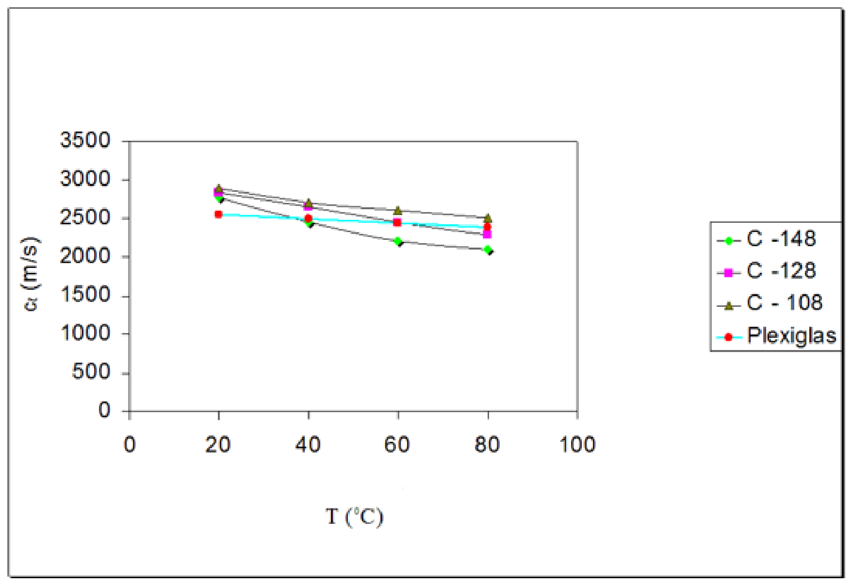
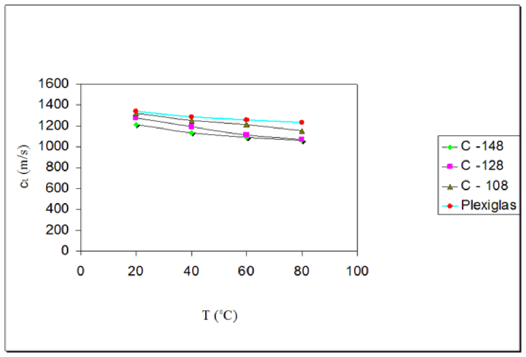
Figure 2 illustrates the variation of the longitudinal wave velocity with temperature for plasticized epoxy resins as well as for PMMA as obtained from ultrasonic experiments. Similarly, Figure 3 shows the variation of the transverse wave velocity versus temperature for these materials. It can be observed that for both of them, velocities decrease when the temperature increases. Moreover, for epoxy resins, the augmentation of plasticizer percentage diminishes the wave velocities. This occurs because epoxy resins are viscoelastic materials, the behaviour of which depends on the temperature and time, exhibiting a term that emphasizes their position between viscous fluids and plastic solids. In an intermediate temperature range, the glass transition region appears to be viscoelastic [31]. At low temperatures, polymers may be glasslike, whereas at higher temperatures, the same polymer tends to be rubberlike and has a reduction in wave velocities.
The determination of the magnitude and the nature of the change in the wave velocity with temperature may be performed by the bond energy of the atoms constituting the main chain of the polymer, i.e., intramolecular interaction, and the interaction energy between the components of adjacent polymer chains, i.e., the intermolecular interaction energy [45].
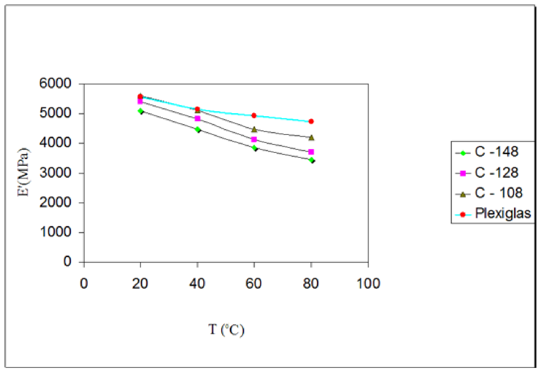
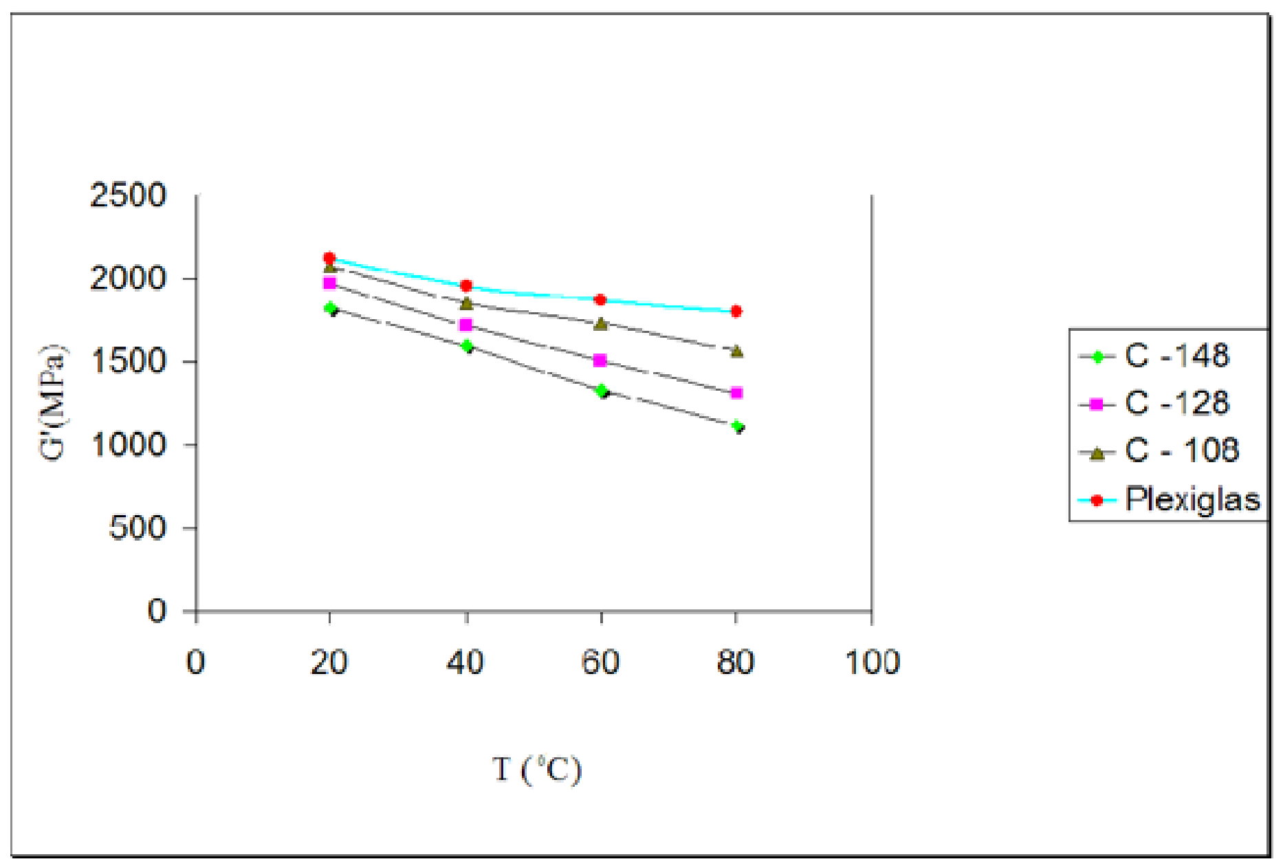
Figure 4 and Figure 5 illustrate the variation in the dynamic moduli E′ and G′ of the epoxy resins and PMMA vs. temperature. Some of the previously mentioned results are observed again, since the two moduli strongly depend on the wave velocity, as can be seen from Equation (1). The modulus of the materials diminishes as the temperature increases. Similarly, in epoxy resins, the modulus decreases when the percentage of plasticizer augments. As previously stated, resins and PMMA are viscoelastic. Therefore, at low temperatures, they are glasslike with an elastic modulus from 1 GPa to 5 GPa. At higher temperatures, the same polymers are rubberlike; the modulus decreases significantly because wave velocities decrease.
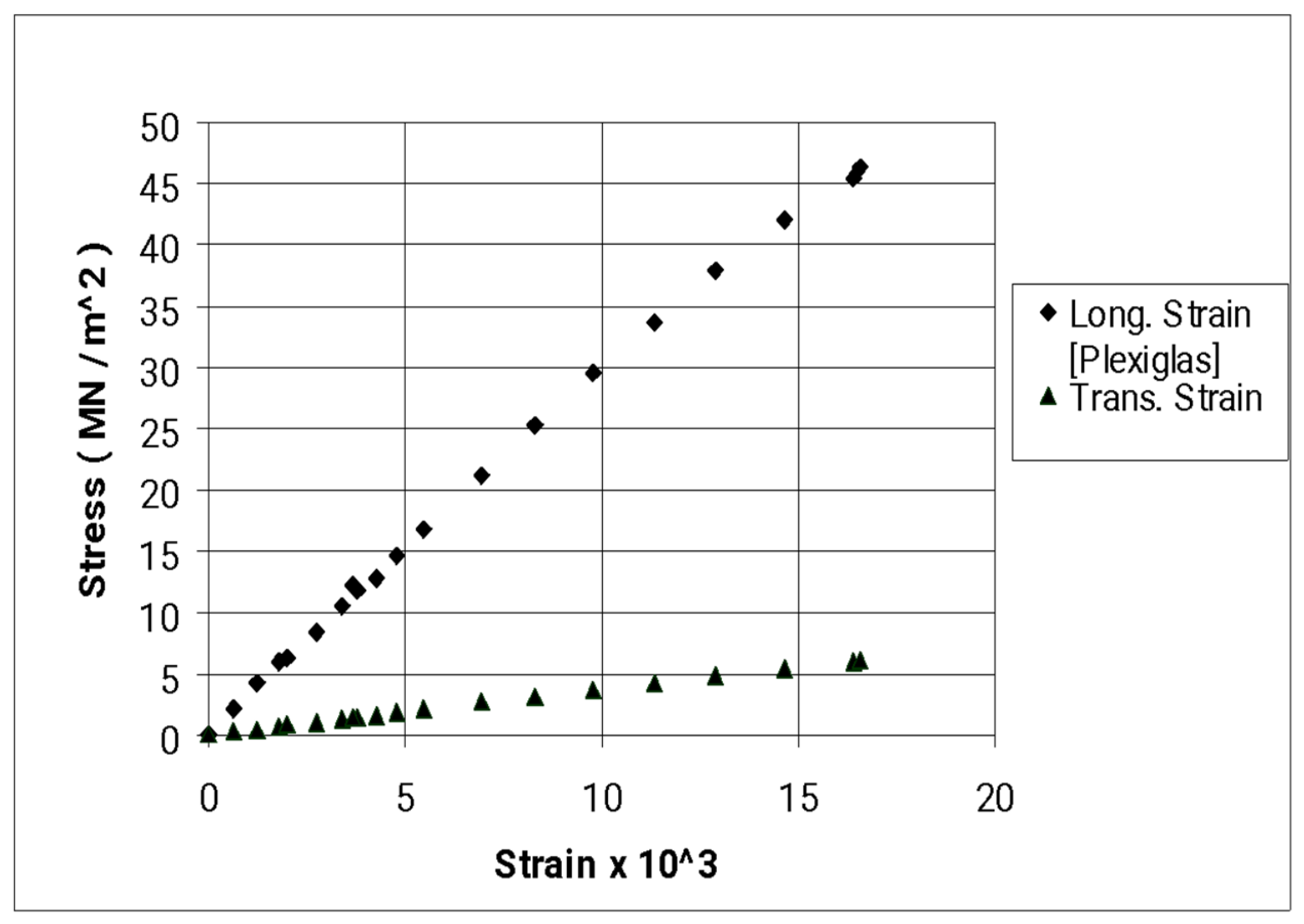
Next, Figure 6 shows the stress–strain diagram of PMMA at the longitudinal and transverse directions, respectively, as determined by tensile tests. This was merely expected due to the microstructure of polymeric materials since they may be glassy solids or viscous fluids, because their mechanical properties are dependent on the conditions during experiments [loading rate, temperature, and strain]. As mentioned previously, at low temperatures, a polymer is glasslike with a relatively high modulus and may fail at strains more than 5%. When the temperature becomes higher, the same polymer is rubberlike with a relatively low modulus and can withstand large extensions, even up to 100%.
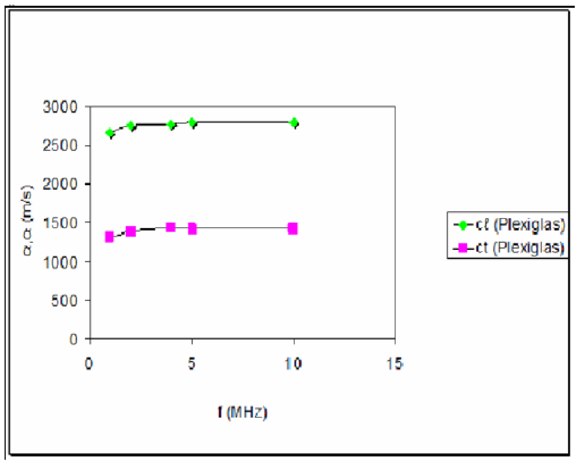
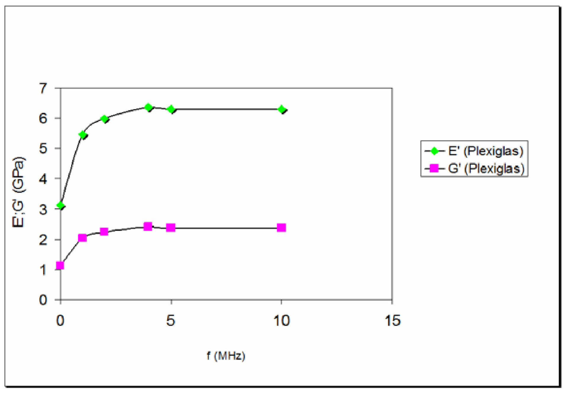
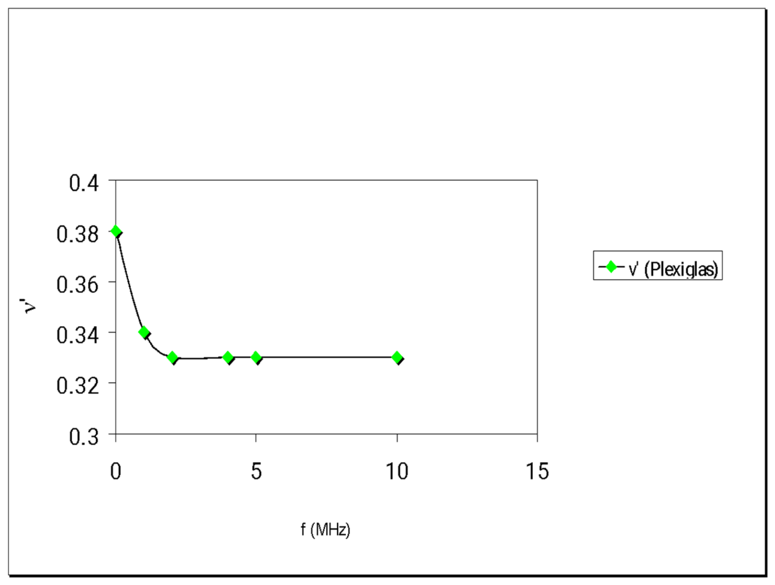
In Figure 7 the variation of both longitudinal and transversal wave velocities vs. frequency f is illustrated whereas Figure 8 and Figure 9 illustrate the variation of the dynamic magnitudes E′, G′, and ν′ with respect to frequency, as obtained from ultrasonic tests using the wave velocities and the formulas in Equation (3). The wave velocities as well as E′ and G′ augment with increasing f, contrary to ν′, which diminishes, showing that the dependence of the dynamic magnitudes E′, G′, and ν′ of viscoelastic materials on wave frequency is very strong, in contrast to elastic materials, where the influence of the wave frequency on their dynamic moduli is not so significant. This means that if frequency, f, tends to zero [the case of static loading], then the dynamic moduli are too close to the static moduli (For example, E′ tends to Est = E). But if f tends to infinity [the case of dynamic loading], then the dynamic moduli depend on the material structure [46]. As an example, from Figure 8, it can be observed that for f = 0 MHz, E′ = ~3 GPa, whereas for f = 10 MHz, E′ = ~6 GPa, namely twice. The values of Est and νst can be found in Figure 6 and compared with those in Figure 8. Thus, this case confirms the previously mentioned properties of elastic or viscoelastic materials. Of course, a satisfactory knowledge of the relevant viscoelastic theory is necessary to understand this behaviour of materials. Hence, by following the corresponding relaxation theory of polymers, we take into consideration how a sound wave propagates in an isotropic viscoelastic material, and even in a macroscopically isotropic material, in which several relaxation processes can take place [47]. Most solid polymers belong to such media. In addition, real viscoelastic materials are usually described not only by a single relaxation time but by a spectrum of relaxation times. There are several reasons for the appearance of such a spectrum. They include different rates of relevant processes in different parts of the body and the presence of different relaxation mechanisms. In polymers, due to the existence of long chains, and the particular nature of intermolecular interactions can result in the appearance of relaxation times.
Now, let us examine the previously mentioned observations by considering the relaxation mechanisms. In Ref. [33], it is reported that the frequency of the elastic wave, as well as the two basic properties, which are the viscosity and the elasticity of these materials, strongly affect the moduli given in Equation (1a–c). This influence appears in an expression [37] where phase velocity C depends on the angular frequency ω = 2πf, the relaxation time τ = η/E, (where η is the viscosity), the density of the spectrum of relaxation times H(τ), and also the limit velocity C0, which corresponds to the static modulus E [1]. By observing this relationship, it can be noticed that when ωτ --> 0 the phase velocity C tends to be equal to C0, i.e., C = C0. This implies that either the frequency f ---> 0 [static loading] or the relaxation time τ ---> 0, which denotes highly elastic states [low viscosity and high elasticity]. The other limiting case, when ωτ --> oo, denotes that when the frequency f or the relaxation time τ [high viscosity and low elasticity] increase, the velocity of the waves should also increase, tending to a limiting value [35].
Here, it may be observed that in all cases these graphs tend to be parallel to the horizontal axis (tend asymptotically) when frequency tends to infinity (practically for high rates of frequency). However, in Figure 9, where the variation of Poisson’s ratio is presented with respect to the frequency, this magnitude diminishes with increasing frequencies. Nevertheless, one may point out that in this diagram the curve derived from the values of this dimensionless quantity becomes a line as well, when frequency tends to infinity, i.e., for high rates.
The interrelation among the chemical structure, physical structure, and molecular mobility of polymers, as well as previously mentioned parameters such as wave velocity, absorption of sound, and the components of the moduli, are the main factors of this behaviour [45]. The magnitude and the nature of the change in moduli and the wave velocity versus frequency and/or temperature are also determined by the bond energy of the atoms forming the principal, polymer chain (energy of intramolecular interaction) and that of the interaction between the elements of adjacent polymer chains (energy of intermolecular interaction). The magnitude of the dynamic moduli of the same polymer is also largely affected by the nature of the interaction in glassy and rubbery state [48].
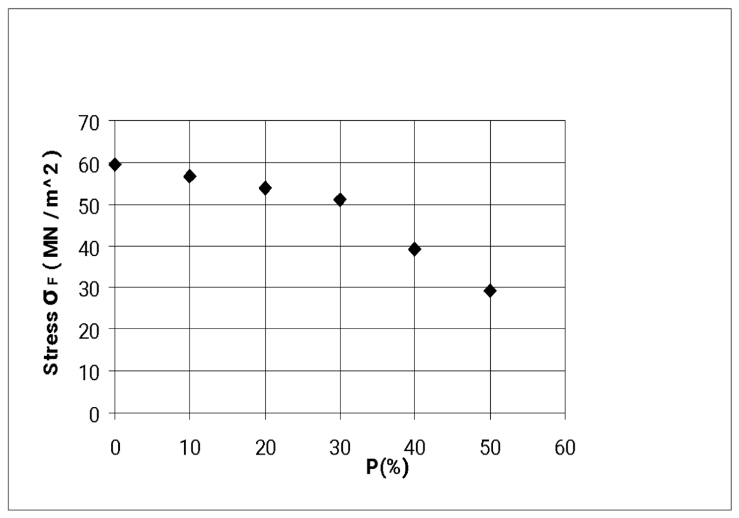
On the other hand, Figure 10 illustrates the variation in tensile stress at fracture, σF, as obtained from related tensile experiments on plasticized epoxy resin at room temperature. It is obvious that σF decreases as the percentage of plasticizer increases, and even more abruptly when P > 25%, where the influence of plasticizer becomes “stronger”.
Normally, a curve may be fitted numerically to these results, although, as it is known, they do not follow the path of a mathematical curve. However, it can be observed that a “wide” second-degree parabola may be suitable.
Therefore, let us consider the parabola σ(P) = AP2 + BP + C, where P denotes the plasticizer percentage, whereas A, B, and C denote the constants of the parabola that should be determined from the diagram, roughly, that: For P = 0% -> σ = 60 MPa -> C = 60. For P = 50% -> σ = 30 MPa, that yields: 2500A + 50B + 60 = 30. Then, since we know that the fracture stress decreases by the addition of plasticizer, the derivative should have a maximum for P = 0%.
Thus: σ′ (0) = 2AP + B = 0. The solution of the equations yields: B = 0 and A = −3/250. Thus, the obtained values for the stresses are: σ (10) = 58.8 MPa, σ (20) = 55.1 MPa, σ (30) = 49.2 MPa, σ (40) = 40.8 MPa, whereas the experimental values are: σ (10) = 57.3 MPa, σ (20) = 54.2 MPa, σ (30) = 50.1 MPa, σ (40) = 40 MPa, respectively, a fact which does not show large discrepancies between them.
However, this parabolic approach, which yields good results from 0% to 50%, cannot correctly describe the behaviour of the experimental results, because for P > 60%, negative values are obtained, a fact that is not possible, since it is known that the fracture stress should continuously decrease up to P = 100%, a value that will be the minimum. Therefore, a point of inflexion should exist for P > 50%. Hence, for this reason, a third-degree parabola, of the form σ(P) = AP3 + BP2 + CP + D, will be assumed. The constants A, B, C, and D will be calculated by taking into consideration experimental values and their path as follows:
For P = 0% -> σ = 60 MPa -> D = 60, For P = 50% -> σ = 30 -> 125,000A + 2500B + 50C + 60 = 30.
At P = 0%, the curve should have its maximum. Since σ′(P) = 3AP2 + 2BP + C -> σ′ (0) = 0 -> C = 0.
At P = 100%, the curve should have its minimum. -> σ′ (100) = 0 -> 30,000A + 200B = 0.
The point of inflexion can be found from σ′ = 0 -> σ″(P) = 0 -> 6AP + 2B = 0.
From the solution of the system, we obtain the values: σ (10) = 58.32 MPa, σ (20) = 53.76 MPa, σ (30) = 47.04 MPa, σ (40) = 38.9 MPa, σ (50) = 30 MPa. It can be said that there are no significant discrepancies between the two series of values and the experimental results given previously in the case of the parabola of the second degree. As to the values for P > 50%, they are: σ (60) = 21.12 MPa, σ (70) = 12.96 MPa, σ (80) = 6.24 MPa, σ (90) = 1.68 MPa, σ (100) = 0.1 MPa. Of course, these values should be compared with experimental results after performing respective experiments to verify any discrepancies.
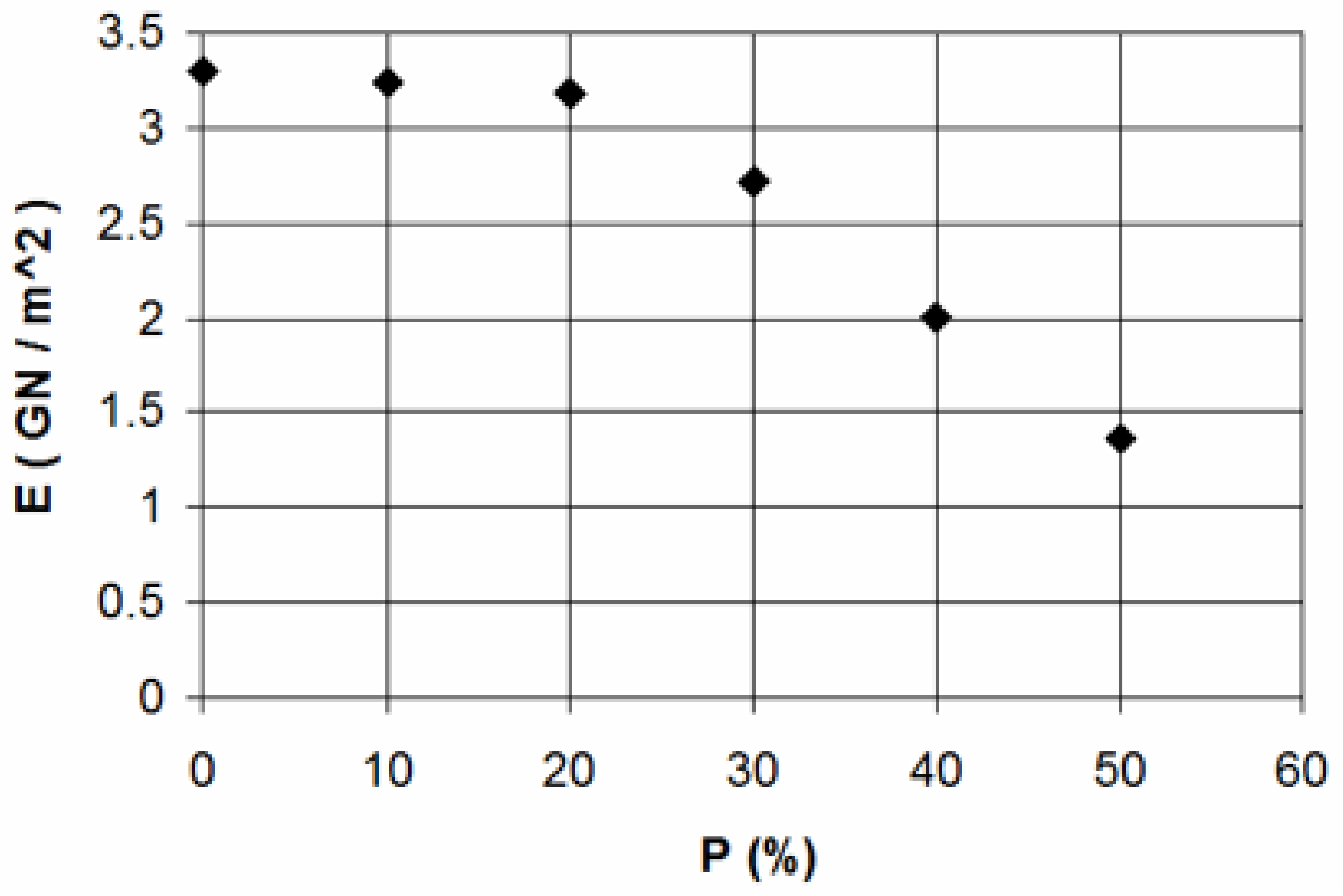
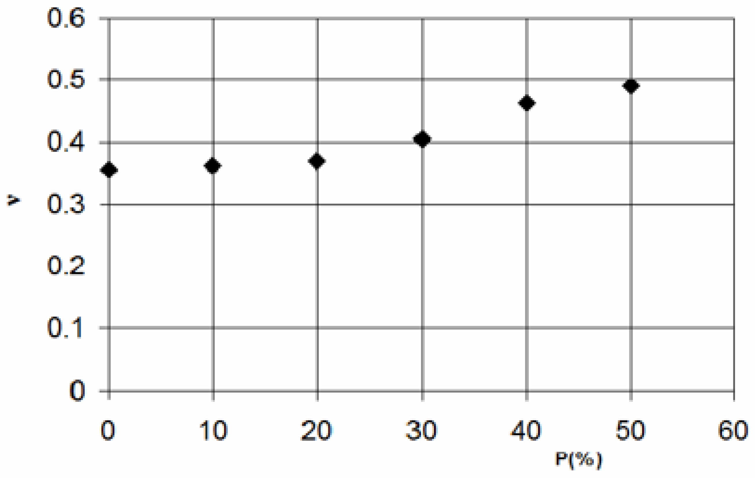
In Figure 11 and Figure 12, variations in tensile modulus and Poisson ratio appear for various amounts of plasticizer P as obtained from destructive tests. Here, one may note that the tensile modulus of the epoxy resin diminishes more abruptly when P exceeds 25% when, as mentioned before, the influence of plasticizer becomes “stronger”. Therefore, one may interpret this fact, again, in accordance with the microstructure of this viscoelastic polymer.
By observing the form of the experimental results, it can be considered that similar parabolic approximations, such as those for tensile stress at fracture, may also be assumed for the elastic modulus. As explained before, we shall consider only the third-degree parabola. Also, it will be assumed that the experiments should be carried out up to P = 100%, which is the maximum plasticizer percentage. Then:
E(P) = AP3 + BP2 + CP + D and E′ (P) = 3AP2 + 2BP + C
To evaluate A, B, C, and D, let us take into consideration the following conditions:
For P = 0 --> E (0) = E0 --> D = E0, and since at P = 0 a maximum should exist, for P = 0 --> E′ (0) = 0 --> C = 0.
Also, For P = 100% or P = 1 --> E (1) = E1 --> A + B +D = E1, and since at P = 100% or P = 1, a minimum should exist, for P = 1 --> E′ (1) = 0 --> 3A = 2B = 0.
The value of E1 is not known because the experiments carried out up to P = 50% or P = 0.5, with E (0.5) = ~1.35 MPa. Hence, the solution of the system A + B = E1 − E0 and 3A + 2B = 0 will give the values of constants A and B. An inflexion point for P can be found from
E″ (P) = 0 --> 6AP + 2B = 0.
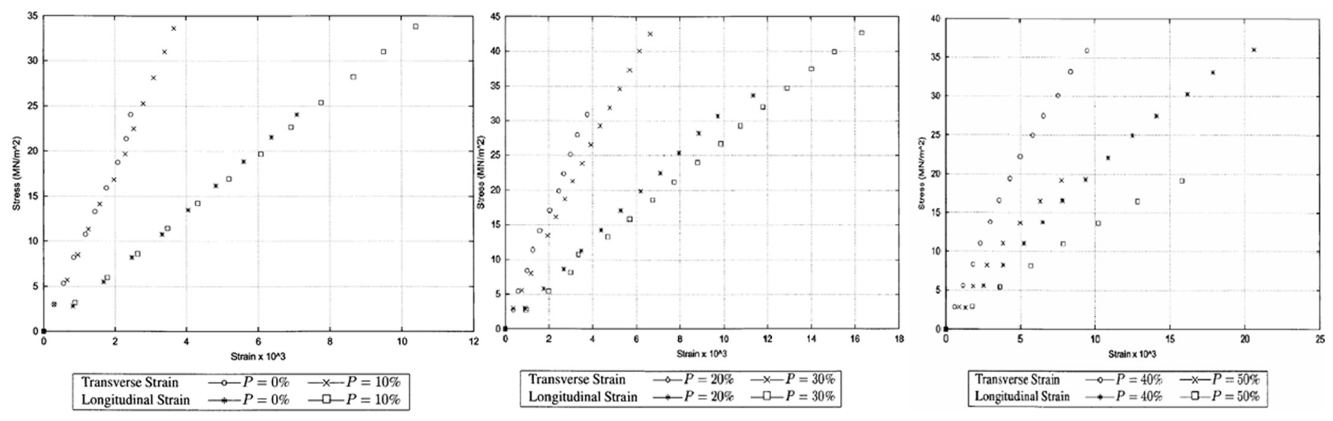
Figure 13 illustrates the stress–strain diagrams of epoxy resin in the longitudinal and transverse directions for various amounts of plasticizer P obtained from tensile experiments, to ascertain the influence of plasticizer on some properties. Mainly, from Figure 13, it can be noticed that pure epoxy resin specimens without plasticizer appear to have a more brittle failure behaviour compared to plasticized specimens since the tensile strain increased by adding plasticizer. A primary reason for this amelioration may be attributed to a possible change in crosslinking density and effective bonding among the components of the epoxy resin [2].
Regarding material stiffness, the elastic modulus clearly decreases. Analogous behaviour is also observed for the strength of polymerized epoxy resin.
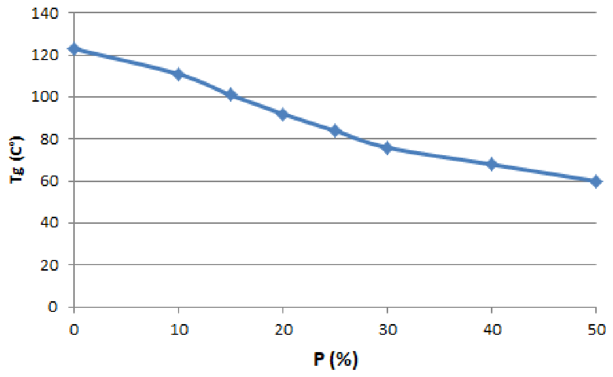
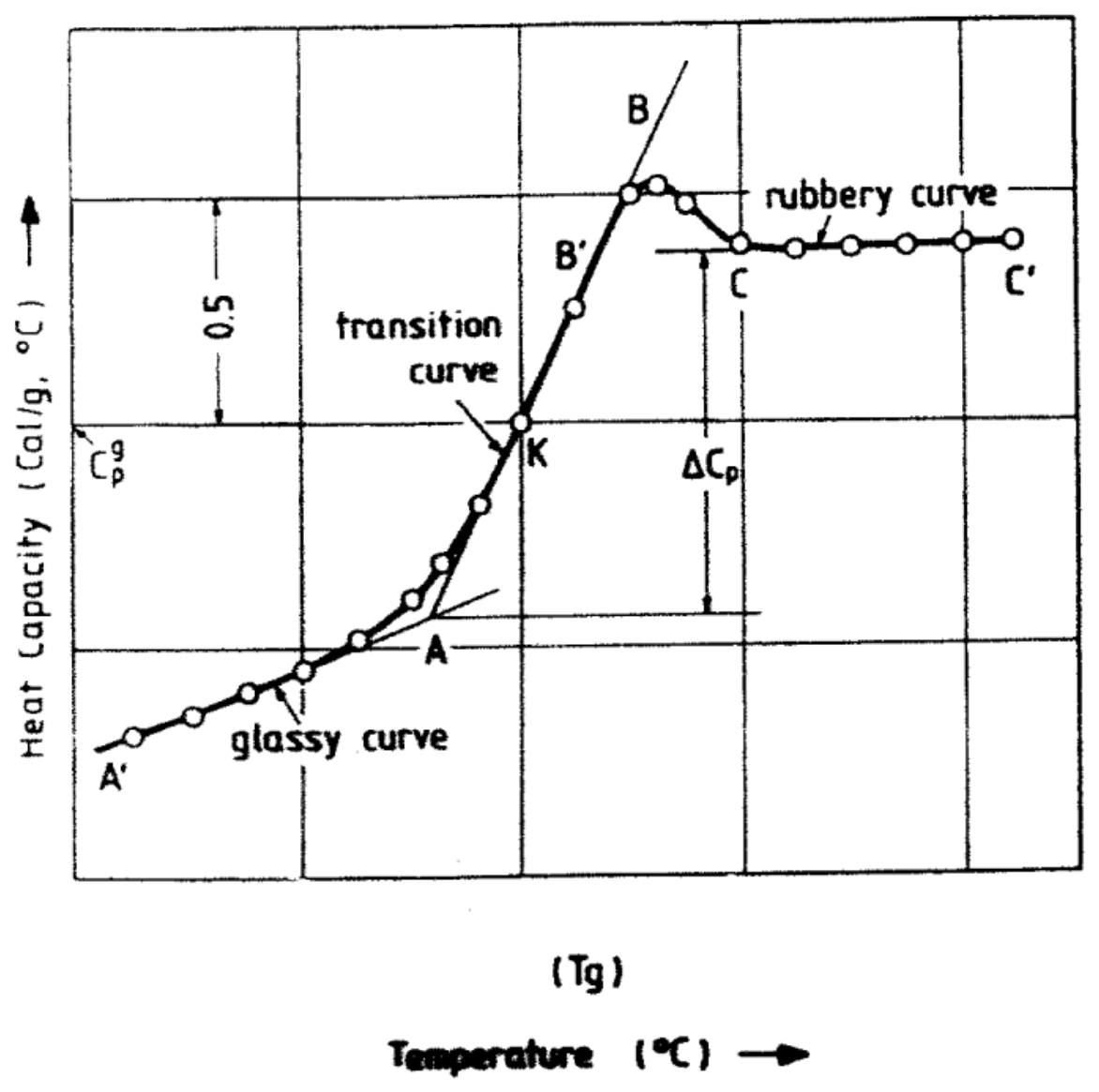
Figure 14 illustrates the change in the glass-transition temperature Tg vs. the amount of plasticizer as obtained from thermal capacity measurements. It can be observed that there is a continuous decrease in Tg values when the plasticizer percentage increases. This behaviour of the plasticized epoxy resins is analogous to that of iron particle reinforced epoxies as observed in Ref. [1]. On the other hand, the temperature dependence of specific heat and the evaluation of Tg is presented in Figure 15. From these figures, it is deduced that, together with a variation in the temperature location of the transition area, displayed by a brusque change in heat capacity, also, a diminution in the sudden change in specific heat ΔCp into the glass transition region, as the plasticizer amount increases. ΔCp is closely related to the number of macromolecules that take part in the cooperative course of Tg. Therefore, the variation of ΔCp with the increase of plasticizer content relates to the macromolecules, which are characterized by a reduced mobility, when a comparison with the corresponding mobility of the macromolecules in a matrix without plasticizer is performed.
An explanation for the kind of transition may be stated as follows. For temperatures exceeding Tg, a freedom of rotation exists around bonds within the molecule, and thermal agitation energy is adequate to suppress the forces of attraction among molecules. As the temperature decreases, the thermal agitation energy of chain segments gradually diminishes until it reaches a point where it is no longer adequate to suppress the intermolecular forces. At that time, the chain parts become “frozen” in steady positions, likewise do the molecules in an ordinary solid. Under these circumstances, changes in molecular conformity, arising from rotation around bonds, are overcome, and with them the ability to sustain deformations of the rubber-like type [49].

5. Conclusions

From the performed, mainly experimental, study, the following conclusions can be mentioned:
(1)
A non-linear increase occurs in the velocity of both longitudinal and transverse waves diffusing in epoxy resins with plasticizer, as its amount augments.
(2)
Moreover, there is dependence of the wave velocities, which are material characteristics, on the discrete nature of the internal structure of the polymers, which may be modified. Usually, in such materials, microstructural damage accumulation is due to void formation.
(3)
The Dynamic Modulus of the two types of polymers increases as the frequency also increases. This intensive increase is due to the particular molecular mechanisms of polymers.
(4)
The increase in frequency causes similar results to the decrease in temperature.
(5)
The Dynamic Modulus at very high frequencies tends to a limited value, which is more than twice the Static Elastic Modulus.
(6)
The larger increase in the Dynamic Modulus is observed up to the frequency of 1 MHz
(7)
The change in the Dynamic Modulus seems to modify the behaviour of the materials from ductile to brittle.
(8)
Tg values decrease as the percentage of plasticizers increases.
(9)
There is always a decrease in tensile strength and tensile modulus, whereas an increase in the Poisson ratio occurs with the addition of plasticizer.
(10)
The comparison of the elastic modulus and Poisson ratio between tensile and ultrasonic measurements shows remarkable divergencies. The results obtained through ultrasonic measurements are superior to those from tensile tests for the elastic modulus but inferior to those for the Poisson ratio due to the nature of viscoelastic materials [50].
(11)
For high frequency values, the longitudinal and transverse wave velocities of PMMA differ by almost a constant quantity.
(12)
For such viscoelastic materials, it can be mentioned that the material constants obtained from ultrasonic measurements are close to those obtained from vibration experiments, due to the influence of frequency on the properties of such materials, a fact that, usually, is not met in metals, alloys, concrete, etc.
(13)
The investigation of the thermomechanical as well as the acoustical behaviour of epoxy and polyester resins is of great interest in experimental mechanics, where their use as model materials is significant. The variation in their properties with composition leads to their use for the simulation of the elastic behaviour of other materials and also to their increased use in fibrous composites and nanocomposites, and thus promotes the investigation in various contemporary research fields [51]. Therefore, the non-destructive method of ultrasonics can be very useful and significant for, mainly, solving fracture mechanics problems.

Author Contributions

Conceptualization, E.S. and E.E.T.; methodology, E.S.; software, E.E.T.; validation, E.S. and E.E.T.; formal analysis, E.S.; investigation, E.E.T.; resources, E.S.; data curation, E.E.T.; writing—original draft preparation, E.S.; writing—review and editing, E.E.T.; visualization, E.S.; supervision, E.S.; project administration, E.E.T.; funding acquisition, E.E.T. All authors have read and agreed to the published version of the manuscript.

Funding

This research received no external funding.

Institutional Review Board Statement

Not applicable.

Informed Consent Statement

Not applicable.

Data Availability Statement

The original contributions presented in the study are included in the article: further inquiries can be directed to the corresponding author.

Conflicts of Interest

The authors declare no conflicts of interest.

References

  1. Sideridis, E.; Prassianakis, I.N.; Kytopoulos, V.N. Storage and loss moduli behavior of plasticized epoxy polymers over a frequency and temperature range, and damaging effects assessment by means of the NDT method of ultrasounds and moisture absorption. J. Appl. Polym. Sci. 2006, 101, 3869–3880. [Google Scholar] [CrossRef] [Scilit]
  2. Okoro, C.; Mohammed, Z.; Jeelani, S.; Rangari, V. Plasticizing effect of biodegradable dipropylene glycol bibenzoate and epoxidized linseed oil on diglycidyl ether of bisphenol A-based epoxy resin. J. Appl. Polym. Sci. 2021, 138, 50661. [Google Scholar] [CrossRef] [Scilit]
  3. Rajak, D.K.; Pagar, D.D.; Kumar, P.; Singh, S. Green Composites: A review of processing technologies and recent applications. J. Thermoplast. Comp. Mater. 2020, 33, 1145. [Google Scholar] [CrossRef] [Scilit]
  4. Huang, J.; Li, N.; Xiao, L.; Liu, H.; Wang, Y.; Chen, J.; Nie, X.; Zhu, Y. Fabrication of a highly tough, strong, and stiff carbon nanotube/epoxy conductive composite with an ultralow percolation threshold via self-assembly. J. Mater. Chem. A 2020, 7, 15731–15740. [Google Scholar] [CrossRef] [Scilit]
  5. Chen, Y.; Li, Q.; Li, C.; Dai, Z.; Yan, H.; Zhu, M.Z.; Zhang, Y.; Yao, Y.; Li, Q. Regulation of multidimensional silver nanostructures for high-performance composite conductive adhesives. Compos. Part A Appl. Sci. Manuf. 2020, 137, 106025. [Google Scholar] [CrossRef] [Scilit]
  6. Dagdag, O.; Berisha, A.; Safi, Z.; Hamed, O.; Jodeh, S.; Verma, C.; Ebenso, E.E.; El Harfi, A. DGEBA-polyaminoamide as effective anti-corrosive material for 15CDV6 steel in NaCl medium: Computational and experimental studies. J. Appl. Polym. Sci. 2020, 137, 48402. [Google Scholar] [CrossRef] [Scilit]
  7. Chae, G.S.; Park, H.W.; Lee, J.H.; Shin, S. Comparative Study on the Impact Wedge-Peel Performance of Epoxy-Based Structural Adhesives Modified with Different Toughening Agents. Polymers 2020, 12, 1549. [Google Scholar] [CrossRef] [Scilit] [PubMed]
  8. Sindhu, P.S.; Ghindani, D.; Mitra, N.; Prabhu, S.S. Morphological changes in epoxy resin (DGEBA/TETA) exposed to low temperatures. J. Adhes. Sci. Technol. 2020, 34, 2262–2273. [Google Scholar] [CrossRef] [Scilit]
  9. Wu, T.; Liu, Y.; Li, N.; Huang, G.W.; Qu, C.B.; Xiao, H.M. Cryogenic mechanical properties of epoxy resin toughened by hydroxyl-terminated polyurethane. Polym. Test. 2019, 74, 45–56. [Google Scholar] [CrossRef] [Scilit]
  10. Bagheri, R.; Marouf, B.T.; Pearson, R.A. Rubber-toughened epoxies: A critical review. Polym. Rev. 2009, 49, 201–225. [Google Scholar] [CrossRef] [Scilit]
  11. Wang, J.; Zhang, X.; Jiang, L.; Qiao, J. Advances in toughened polymer materials by structured rubber particles. Prog. Polym. Sci. 2019, 98, 101160. [Google Scholar] [CrossRef] [Scilit]
  12. Sprenger, S. Nanosilica-Toughened Epoxy Resins. Polymers 2020, 12, 1777. [Google Scholar] [CrossRef] [Scilit] [PubMed]
  13. Park, Y.T.; Qian, Y.; Chan, C.; Suh, T.; Nejhad, M.G.; Macosko, C.W.; Stein, A. Epoxy toughening with low graphene loading. Adv. Funct. Mater. 2015, 25, 575–585. [Google Scholar] [CrossRef] [Scilit]
  14. Pham, T.D.; Vu, C.M.; Choi, H.J. Enhanced fracture toughness and mechanical properties of epoxy resin with rice husk-based nano-silica. Polym. Sci. Ser. A 2017, 59, 437–444. [Google Scholar] [CrossRef] [Scilit]
  15. Su, S.; Wang, H.; Zhou, C.; Wang, Y.; Liu, J. Study on epoxy resin with high elongation-at-break using polyamide and polyether amine as a two-component curing agent. e-Polymers 2019, 18, 433–439. [Google Scholar] [CrossRef] [Scilit]
  16. Baig, Z.; Akram, N.; Zia, K.M.; Saeed, M.; Khosa, M.K.; Ali, L.; Saleem, S. Influence of amine-terminated additives on thermal and mechanical properties of diglycidyl ether of bisphenol A (DGEBA) cured epoxy. J. Appl. Polym. Sci. 2019, 137, 48404. [Google Scholar] [CrossRef] [Scilit]
  17. Jiang, S.; Zha, S.; Xia, L.; Guan, R. Synthesis and characterization of diphenylsilanediol modified epoxy resin and curing agent. J. Adhes. Sci. Technol. 2015, 29, 641. [Google Scholar] [CrossRef] [Scilit]
  18. Pan, X.; Mercadé-Prieto, R.; York, D.; Preece, J.A.; Zhang, Z. Structure and Mechanical Properties of Consumer-Friendly PMMA Microcapsules. Ind. Eng. Chem. Res. 2013, 52, 11253–11265. [Google Scholar] [CrossRef] [Scilit]
  19. Krautkramer, J.; Krautkramer, H. Ultrasonic Testing of Materials; Springer: Berlin/Heidelberg, Germany, 1977. [Google Scholar]
  20. ASNT. Nondestructive Testing Handbook, Volume 7: Ultrasonic Testing, 2nd ed.; ASNT: Columbus, OH, USA, 1993; Volume 83. [Google Scholar]
  21. Paterson, D.A.; Ijomah, W.; Windmill, J.F.C. An analysis of end-of-life terminology in the carbon fiber reinforced plastic industry. Int. J. Sustain. Eng. 2016, 9, 130–140. [Google Scholar] [CrossRef] [Scilit]
  22. Roa-Rodriguez, G.; Aperador, W.; Delgado, A. Simulation of Non-Destructive Testing Methods of Ultrasound in Concrete Columns. Int. J. Electrochem. Sci. 2013, 8, 12226–12237. [Google Scholar] [CrossRef] [Scilit]
  23. Santos, P.; Julio, E.; Santos, J. Towards the development of an in situ non-destructive method to control the quality of concrete-to-concrete interfaces. Eng. Struct. 2010, 32, 207–217. [Google Scholar] [CrossRef] [Scilit]
  24. Chai, H.K.; Momoki, S.; Kobayashi, Y.; Aggelis, D.G.; Shiotani, T. Tomographic reconstruction for concrete using attenuation of ultrasound. NDT E Int. 2011, 44, 206–215. [Google Scholar] [CrossRef] [Scilit]
  25. Hale, J.M.; Ashton, J.N. Ultrasonic testing for strength reduction in GRP pressure vessels. Compos. Struct. 1985, 3, 229–239. [Google Scholar] [CrossRef] [Scilit]
  26. Huang, C.-L.; Popovic, J.S. Predicting Axial Stress State in Continuously Welded Rail Using Impulse-Generated Vibration Measurements. Mater. Eval. 2024, 82, 60–66. [Google Scholar] [CrossRef] [Scilit]
  27. Summerscales, J. (Ed.) Non-Destructive Testing of Fibre-Reinforced Plastic Composites; Elsevier Applied Science: Barking, UK, 1987; Volume 2. [Google Scholar]
  28. Rokhlin, S.I.; Chimenti, D.E.; Nagy, P.B. Physical Ultrasonics of Composites; Oxford University Press: Oxford, UK, 2001. [Google Scholar]
  29. Theocaris, P.S. Local Yielding Around a Crack Tip in Plexiglas. J. Appl. Mech. 1970, 37, 409–415. [Google Scholar] [CrossRef] [Scilit]
  30. Theocaris, P.S.; Prassianakis, I.N. Interrelation of mechanical and optical properties of plasticized epoxy polymers. J. Appl. Polym. Sci. 1978, 22, 1725–1734. [Google Scholar] [CrossRef] [Scilit]
  31. Theocaris, P.S.; Paipetis, S.A.; Papanicolaou, G.C. Indentation studies in plasticized epoxy polymers. J. Appl. Polym. Sci. 1978, 22, 1417–1430. [Google Scholar] [CrossRef] [Scilit]
  32. Theocaris, P.S.; Papanicolaou, G.C.; Sideridis, E. Structural Integrity Studies in Particulate Composites by Means of Thermal Capacity Measurements. J. Reinf. Plast. Compos. 1982, 1, 92–106. [Google Scholar] [CrossRef] [Scilit]
  33. Prassianakis, J.N.; Kompoti, N.; Varakis, J. Curing effects on the acoustical properties of epoxy polymers. Exp. Mech. 1993, 33, 77–80. [Google Scholar] [CrossRef] [Scilit]
  34. Prassianakis, I.N.; Theotokoglou, E.N. The attenuation evolution near notch tips in polymers by the NDT method of ultrasounds. Eng. Fract. Mech. 1992, 43, 117–121. [Google Scholar] [CrossRef] [Scilit]
  35. Prassianakis, I.N.; Sideridis, E.; Kytopoulos, V.N.; Prassianakis, N.I.; Papapetrou, V. Destructive and non-destructive tests for the determination of the in-plane properties of chopped strand mat reinforced epoxy laminates. In Proceedings of the 3rd International Conference on NDT, Chania, Greece, 15–17 October 2003. [Google Scholar]
  36. Sideridis, E.; Kytopoulos, V.N.; Prassianakis, I.N.; Sakellaris, I. Acoustic and Mechanical properties of particulate composites. In Proceedings of the International Non-Destructive Testing Symposium and Exhibition, İstanbul, Türkiye, 17–19 April 2008. [Google Scholar]
  37. Theotokoglou, E.E.; Sideridis, E. Nondestructive and Destructive Testing of Reinforced Polymeric Materials. Struct. Longev. 2012, 8, 83–97. [Google Scholar]
  38. Afifi, H.A. Ultrasonic Pulse Echo Studies of the Physical Properties of PMMA, PS, and PVC. Polym.-Plast. Technol. Eng. 2003, 42, 193–205. [Google Scholar] [CrossRef] [Scilit]
  39. Paterson, D.A.; Ijomah, W.; Windmill, J.F.C. Elastic constant determination of unidirectional composite via ultrasonic bulk wave through transmission measurements: A review. Prog. Mater. Sci. 2018, 97, 1–37. [Google Scholar] [CrossRef] [Scilit]
  40. Baptista-Pereira, C.; Meegoda, J.N.; Kewalramani, J.A.; Nadelmann, E.; Elliott, T.; Borgaonkar, A.D. Ultrasound applications in civil and environmental engineering. Acad. Eng. 2025, 2, 1–23. [Google Scholar] [CrossRef] [Scilit]
  41. İlhan, Ü. Static and Dynamic Mechanical Properties of (Bauxite, and Carbon Black) Filled SBR Vulcanizates: Effects of Filler Surface Modification on Properties. Ph.D. Thesis, Middle East Technical University, Faculty of Arts and Sciences, Ankara, Turkey, 1990. [Google Scholar]
  42. Rozenberg, B.A.; Sigalov, G.M.; Aldoshina, M.Z.; Scheck, Y.B. Heterophase Network Polymers: Synthesis, Characteristics and Properties; Rozenberg, B.A., Ed.; CRC Press: London, UK, 2020. [Google Scholar]
  43. Perepechko, I. Acoustic Methods of Investigating Polymers; Mir Publisher: Moscow, Russia, 1975. [Google Scholar]
  44. Kachanov, L.M. Introduction to Continuum Damage Mechanics; Kluwer Academic Publishers: Dordrecht, The Netherlands, 1986. [Google Scholar]
  45. Kaptakov, M.O.; Pegachkova, E.A.; Makarenko, A.V. Physical and mechanical properties of composites polyethylene-Cuo nanoparticles. In AIP Conference Proceedings; AIP Publishing: Melville, NY, USA, 2021; Volume 2402, p. 020038. [Google Scholar] [CrossRef] [Scilit]
  46. Rosmanith, H.P.; Rosakis, A.J. Dynamic Failure of Materials. In Theory, Experiments and Numerics; Springer Nature: Cham, Germany, 1991. [Google Scholar]
  47. Rodriguez Roblero, M.J. Condition Assessment of Concrete Elements Through Two Nondestructive Ultrasonic Techniques. Ph.D. Thesis, University of Ontario, Waterloo, ON, Canada, 2017. [Google Scholar]
  48. Chabane, H. Introduction of Metal-Oxo Nanostructures Associated with Ionic Liquids for the Design of Multi-Functonial Polymer Materials. Ph.D. Thesis, Universite de Lyon, Lyon, France, 2021. [Google Scholar]
  49. Burkert, U.; Allinger, N.L. Molecular Mechanics. In ACS Monograph 177; American Chemical Society: Washington, DC, USA, 1982. [Google Scholar]
  50. Mattice, W.L.; Suter, U.W. Conformational Theory of Large Molecules; Wiley: New York, NY, USA, 1994. [Google Scholar]
  51. Tominaga, Y.; Shimamoto, D.; Hotta, Y. Curing Effects on Interfacial Adhesion between Recycled Carbon Fiber and Epoxy Resin Heated by Microwave Irradiation. Materials 2018, 11, 493. [Google Scholar] [CrossRef] [Scilit] [PubMed]
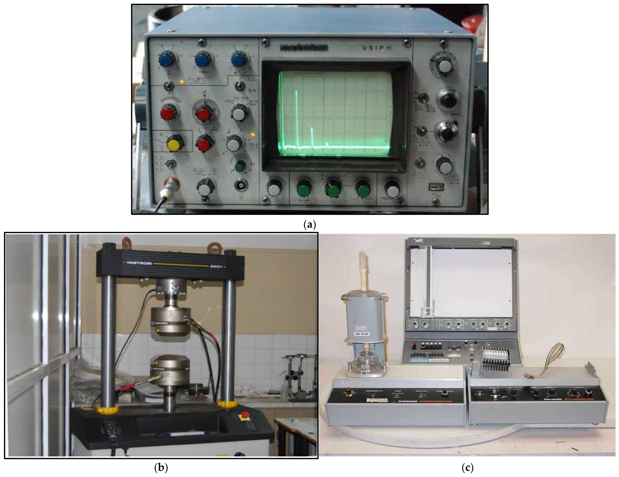
Figure 1. (a) The ultrasonic pulse echo measuring system. (b) Experimental setup for tensile experiments. (c) Experimental setup for thermal (DSC) experiments.
Eng 07 00417 g001
Figure 2. Longitudinal wave velocity vs. temperature.
Eng 07 00417 g002
Figure 3. Transverse wave velocity vs. temperature.
Eng 07 00417 g003
Figure 4. Dynamic Modulus vs. temperature.
Eng 07 00417 g004
Figure 5. Shear Modulus vs. temperature.
Eng 07 00417 g005
Figure 6. Stress–strain diagram of PMMA in the longitudinal and transverse directions.
Eng 07 00417 g006
Figure 7. Longitudinal and transverse wave velocity vs. frequency.
Eng 07 00417 g007
Figure 8. Dynamic elastic and shear moduli vs. frequency.
Eng 07 00417 g008
Figure 9. Poisson’s ratio vs. frequency.
Eng 07 00417 g009
Figure 10. Variation of the tensile stress at fracture vs. plasticizer.
Eng 07 00417 g010
Figure 11. Variation of tensile modulus vs. plasticizer.
Eng 07 00417 g011
Figure 12. Variation of Poisson ratio vs. plasticizer.
Eng 07 00417 g012
Figure 13. Stress–strain diagrams of epoxy resin at the longitudinal and transverse direction for various amounts of plasticizer.
Eng 07 00417 g013
Figure 14. Variation of glass-transition temperature vs. plasticizer.
Eng 07 00417 g014
Figure 15. Determination of glass-transition temperature from Cp-T diagram.
Eng 07 00417 g015
Disclaimer/Publisher’s Note: The statements, opinions and data contained in all publications are solely those of the individual author(s) and contributor(s) and not of MDPI and/or the editor(s). MDPI and/or the editor(s) disclaim responsibility for any injury to people or property resulting from any ideas, methods, instructions or products referred to in the content.