Article

Loading Response of Segment Lining with Pea-Gravel Grouting Defects for TBM Tunnel in Transition Zones of Surrounding Rocks

1
Zhongzhou Water Supply Holding Company Limited, Zhengzhou 450046, China
2
Collaborative Innovation Center for Efficient Utilization of Water Resources, North China University of Water Resources and Electric Power, Zhengzhou 450046, China
3
Xuchang Innovation Center of Intelligent Construction and Building Industrialization Technology, Zhongyuan Institute of Science and Technology, Zhengzhou 451400, China
*
Author to whom correspondence should be addressed.
Eng 2025, 6(7), 166; https://doi.org/10.3390/eng6070166
Submission received: 7 June 2025 / Revised: 13 July 2025 / Accepted: 16 July 2025 / Published: 21 July 2025
(This article belongs to the Topic Hydraulic Engineering and Modelling)

Abstract

Pea-gravel grouting, which fills the gap between the lining of tunnels and the surrounding rock, is crucial for the structural stability and waterproofing of water delivery TBM tunnels. However, it is prone to defects due to complex construction conditions and geological factors. To provide practical insights for engineers to evaluate grouting quality and take appropriate remedial action during TBM tunnel construction, this paper assesses four types of pea-gravel grouting defects, including local cavities, less density, rich rock powder and rich cement slurry. Detailed numerical simulation models comprising segment lining, pea-gravel grouting and surrounding rock were built using the 3D finite element method to analyze the displacement and stress of the segments at the transition zone between different classes of surrounding rocks, labeled V–IV, V–III and IV–III. The results indicate that a local cavity defect has the greatest impact on the loading response of segment lining, followed by less density, rich rock powder and rich cement slurry defects. Their impact will weaken with better self-support of the surrounding rocks in the order of V–IV, V–III and IV–III. The tensile stress of segment lining is within the limit of concrete cracking for combinations of all four defects when the surrounding rock is of the class IV–III, and it is within this limit for two-defect combinations when the surrounding rock is of classes V–III and V–IV. When three defects or all four defects are present in the pea-gravel grouting, the possibility of segment concrete cracking increases from the transition zone of class V–III surrounding rock to the transition zone of class V–IV surrounding rock.

1. Introduction

Today, tunnel boring machines (TBMs) have been commonly applied in tunnel construction for long-distance water delivery to reallocate water resources in different areas of China [1,2,3,4]. Since the TBM tunnels of non-pressurized water delivery systems commonly have no secondary lining, segment lining plays the roles of supporting surrounding rocks and internal waterproofing, which is crucial for safety during construction and operation [5,6,7]. Therefore, studies have been conducted on the production, installation, and load-bearing performance, as well as safety risk assessments, of this kind of segment lining [8,9,10,11]. As such, the pea-gravel grouting used to fill the gap between the segment lining and surrounding rock has begun to receive more attention. Normally, pea-gravel grouting, which consolidates the surrounding rock to a certain extent, contributes to the segments connected with surrounding rocks to transfer external pressure and prevent external water infiltration [6,12,13]. During construction, an adequate number of grout holes in certain places are reserved on the segments, enabling a rational grout process to occur in the order of the bottom, sides and top [13,14,15]. Normally, pea-gravel grouting comprises two steps: filling with pea-gravel and grouting with slurry. After installing a certain number of segments, sufficient pea-gravel is blown into the gap between the segment lining and surrounding rock through the grouting holes, and then the cement slurry is injected to fill the voids in the pea-gravel to form a stable segment lining. To ensure high-quality pea-gravel grouting with sufficient compaction and an even distribution of pea-gravel, the preparation of grouting materials [14,15,16,17] and the quality control of backfilling technics [18,19,20,21,22] are key points of consideration.
However, pea-gravel grouting work is a concealed process that takes place behind the segment lining, which is prone to defects due to complex construction conditions and geological factors. These factors include the tunnel boring machine operation, the geological properties of the surrounding rock, the selection of pea-gravel material, the proportion of cement slurry, the volume ratio of slurry to pea-gravel, the grouting pressure, the grouting closure measures and the rock residuals in the gap between the segment and surrounding rock [23,24,25]. Therefore, the defects of pea-gravel grouting are a practical problem that engineers always face during construction. A study reported that the defects of pea-gravel grouting are most commonly cavities at the arch crown and tunnel bottom, and less density at the lower part of the outside of the line’s turning sections, and these defects increase in probability and scale under bad geological conditions of the surrounding rock, which may lead to collapsed rocks behind the segment lining [22]. This requires an increase in the filling pressure for pea-gravel to improve the filling quality at the arch crown and tunnel bottom, while more attention should be paid if the bad surrounding rock is encountered. Studies indicate that tensile stress could be markedly raised by the local cavities, leading to the cracking of segments in the local cavity zone [23,24]. Meanwhile, a study showed that less dense pea-gravel grouting, especially in the top segment, leads to uneven stress distribution and high tensile stress on the segment, causing large deformation and yielding of the surrounding rock [25]. This necessitates a second slurry grouting that cannot be omitted for the repair of the local cavities and less dense grouting [26,27]. In addition, other defects, including rich cement slurry and rich rock powder, also exist in pea-gravel grouting [14,21,24]. Notably, the impacts of various defects may be magnified with the combined effects of internal water pressure and geological conditions [24,26], whereas segments will be heavily cracked in places with bad grout filling [28]. Generally, although some studies have been conducted to verify the defects of pea-gravel grouting and analyze their impact on the load-bearing status of segment lining, deep understanding has not yet been achieved to give a clear indication of how to reasonably treat different defects during TBM tunnel construction. In addition, current codes only specify the key technical points of grouting operations and quality acceptance, while segment lining relies on displacement monitoring [13,29]. This creates confusion for engineers, who can only make decisions based on experience.
To understand the effect of pea-gravel grouting defects on the loading response of segment lining, the whole structure of a TBM tunnel should be considered in terms of segment lining, pea-gravel grouting and surrounding rock. The solution becomes more complicated due to the defects of pea-gravel grouting, which cannot be rationally calculated with the analytic formulas deduced from the traditional method of structural mechanics. Although an experimental study can be applied to obtain detailed understanding of the structural performance, it is always difficult to simulate the real conditions of an engineering project. As such, numerical modeling using the finite element method (FEM) has been commonly used to obtain the internal forces of non-rod concrete structures, as specified in China code SL 191 [30]. Compared to an experimental study, numerical modeling has the advantage of accounting for more factors with a remarkable reduction in research cost, becoming a common approach for the analysis of non-rod structures [11,22,23,24,25]. For instance, the FEM has been applied to the analysis of prestressed concrete cylinder pipes under internal water pressure [31,32], the influence of a large-diameter intercity railway tunnel underground passing the main canal of the middle route of the South-to-North Water Diversion Project [33], the mechanical properties of a large-scale silo [34] and prestressed concrete lining withstanding the prestress of steel strands [35]. The analytical results of the FEM agree well with the experiments when proper numerical models are built with reasonable materials and constitutive relationships. Meanwhile, 3D FEM numerical models have been successfully applied in the analysis of TBM tunnel for water delivery. Li et al. [11,36] studied the load-bearing performances of TBM tunnel segment lining with misaligned assembly using 3D FEM numerical models, providing insight into segment assembly with confined misalignment between adjacent segments. Zhao et al. [37] studied the load-bearing performance of TBM tunnel segment lining affected by softened basement due to internal water leakage under V-class surrounding rock, providing a technical basis for the safe operation monitoring of a water delivery tunnel with water leakage.
Generally, existing studies have been conducted on a single defect of pea-gravel grouting, such as local cavities and less density. Further studies are still necessary on the effects of other defects and their combinations. Given the experimental difficulty of real TBM tunnels, the FEM is a realistic method for simulating a TBM tunnel with pea-gravel grouting defects. In this study, four types of pea-gravel grouting defects and their distribution are drawn from the on-site inspections of practical engineering and relevant studies [14,22,23,24,25,26,27,28], and the numerical models comprising segment lining, pea-gravel grouting and surrounding rock are formed using a 3D FEM to receive the loading responses of the TBM tunnel with pea-gravel grouting defects under class III, IV and V surrounding rocks [38]. This paper reports the analytical results of the displacement and stress distributions of segment lining in the transition zone between different classes of surrounding rocks, labeled V–IV, V–III and IV–III. Concerning the peak values and distribution of the vertical and horizontal displacements and the circumferential stresses, the worst impact of the pea-gravel grouting defects on the loading performance of the segment lining is recognized. This can help engineers who face the problem of treating pea-gravel grouting defects, to evaluate the quality of pea-gravel grouting and take professional countermeasures.

2. Numerical Models of TBM Tunnel Structures

2.1. FEM Numerical Models

The background of this study relied on the TBM hydraulic tunnel of Anyang City’s West Route of the South-to-North Water Diversion Project [11,36,37,38]. The segments of the shield tunnel are hexagonal honeycomb-shaped with a thickness of 0.3 m and width of 1.2 m. The segment lining has a 3.5 m inner diameter and 4.1 m outer diameter. Each ring of the segment lining consists of four segments assembled in a staggered manner, and the adjacent segments are connected by two locating pins in the ring joints. The longitudinal contact surfaces of the segments are connected using slots. Meanwhile, the excavated sectional diameter of the tunnel is 4.33 m, which provides a gap filled by the pea-gravel grouting with a thickness of 115 mm.
Seven rings of segments were considered to build the 3D FEM numerical model of the TBM tunnel with different pea-gravel grouting defects, using the finite element software of ANSYS 17.0 (ANSYS Inc., Canonsburg, PA, USA, www.ansys.com, accessed on 10 February 2024). The central transverse section of the numerical model was set at the transition zone of different classes of surrounding rocks, which was the main analytic target for determining the displacement and stress distribution of the segments. The entire numerical model was built with the original coordinates at the sectional center of the tunnel, with the x-axis and y-axis as the transverse horizontal and vertical directions of the tunnel section, and the z-axis as the longitudinal direction along the tunnel [11,36,37,38]. To minimize boundary effects, the boundary should be determined with a distance from the lining of no less than 5–10 times the tunnel diameter [11,31,32,35]. Combined with the simulation analysis of the initial stress equilibrium of surrounding rocks during the TBM excavation, and in ensuring minimized boundary effects on the loading response of the tunnel structures, the boundaries were 25 m from the center of the tunnel.
To build the numerical models, the mesh of surrounding rocks was first divided to simulate the initial excavation to achieve stress equilibrium, followed by the successive formation of pea-gravel grouting, segment lining and locating pins. The pea-gravel grouting, segments and surrounding rocks were simulated using SOLID45 elements, while the locating pins were simulated using BEAM188 elements. To ensure the accuracy of analysis in complex geometries, all numerical model meshes were divided using mapped hexahedral elements. The surrounding rock within a 4 m radius of the tunnel was more finely meshed. The contact surfaces between the adjacent segments, and the pea-gravel grouting and segment, are simulated using TARGE170 target elements, which describe the 3D target surfaces with CONTA173 contact elements. CONTA173 contact elements are four-node surface-to-surface contact elements, which describe the contact and sliding conditions between the TARGE170 target elements and the deformable surfaces defined by these elements [11,36,37,38,39,40]. The interfaces between the segments and surrounding rocks and those between the segments were set as face-to-face contacts, which complied with Coulomb’s law of friction along the tangent direction. When the tangential stress reached a critical value, slipping was created with a friction coefficient of 0.5 [34,36,40]. A hard contact was applied to the normal direction of the interfaces, which was allowed to separate.
The built numerical model is shown in Figure 1, where the light green and blue parts express different classes of surrounding rocks. The vertical boundaries were constrained in the normal direction, and the bottom boundary was fixed in all three directions.
With regarding to the inspection results of pea-gravel grouting quality reported [25,26,27,28], and based on the project detection [38], rational assumptions for the common scale and location of four types of pea-gravel grouting defects were set in the numerical models as shown in Figure 2. The local cavity defect was set within the range of a 30° central angle with the top as the center. The rich rock powder defect was set within the range of a 30° central angle with the bottom as the center. The less dense grouting defect was set within the range of a 30° central angle with central angles of 45° and 315° as the center. The rich grouting slurry defect was set within the range of a 30° central angle with central angles of 135° and 225° as the center.
Before the final analysis of numerical results, mesh sensitivity analysis was first conducted to ensure that the results of the 3D FEM were not dependent on mesh size or configuration, especially in regions related to the pea-gravel grouting defects that might create high-stress concentration.

2.2. Constitutive Relationships of Materials

A segment was produced with C50W8F100 concrete with a 50 MPa strength grade, W8 class of water penetration resistance and F100 class of freezing and thawing resistance; the main physical and mechanical properties are presented in Table 1. A nonlinear constitutive relationship specified in China code GB 50010 [41] was set for segment concrete. For the hydraulic concrete structures, the cracking resistance of concrete was taken as the limit of 0.85 times the tensile strength, as specified in China code SL 191 [30]; that is, the tensile stress was limited within 0.85 × 2.64 MPa = 2.24 MPa.
The physical and mechanical parameters of pea-gravel grouting with or without defects are summarized in Table 2, which are determined based on the statistical analysis of test data of engineering projects [38,42]. Due to pea-gravel grouting being a kind of concrete with small-particle aggregate, a nonlinear relationship regarding that of concrete [41] was applied for the constitution of intact pea-gravel grouting. The local cavity defect was simulated using life-and-death elements to kill the elements in the defect range. Another three defects like less density, rich rock powder and rich cement slurry were simulated by re-assigning material parameters of the Drucker–Prager yield criterion [40,42].
Except for a portion of the length passing through a coal geological condition, the surrounding rocks of the TBM tunnel can be divided into classes III, IV and V according to China code GB 50218 [43] and related studies [38,44]. The total lengths of classes III, IV and V are 8054 m, 3224 m and 1843 m, respectively, which account for 61.1%, 24.5% and 14.0% of the total length. Therefore, multi-transfer sections between different classes of surrounding rocks exist in this project. The properties of the surrounding rocks are summarized in Table 3. The Mohr–Coulomb constitutive model was used for the simulation of surrounding rocks [38,40], which can effectively describe and predict the behavior of surrounding rocks under the compression–shear status around the tunnel.
In addition, the constitutive relationship of locating pins was set as linear elastic with a tensile strength of 310 MPa and a modulus of elasticity of 210 GPa.

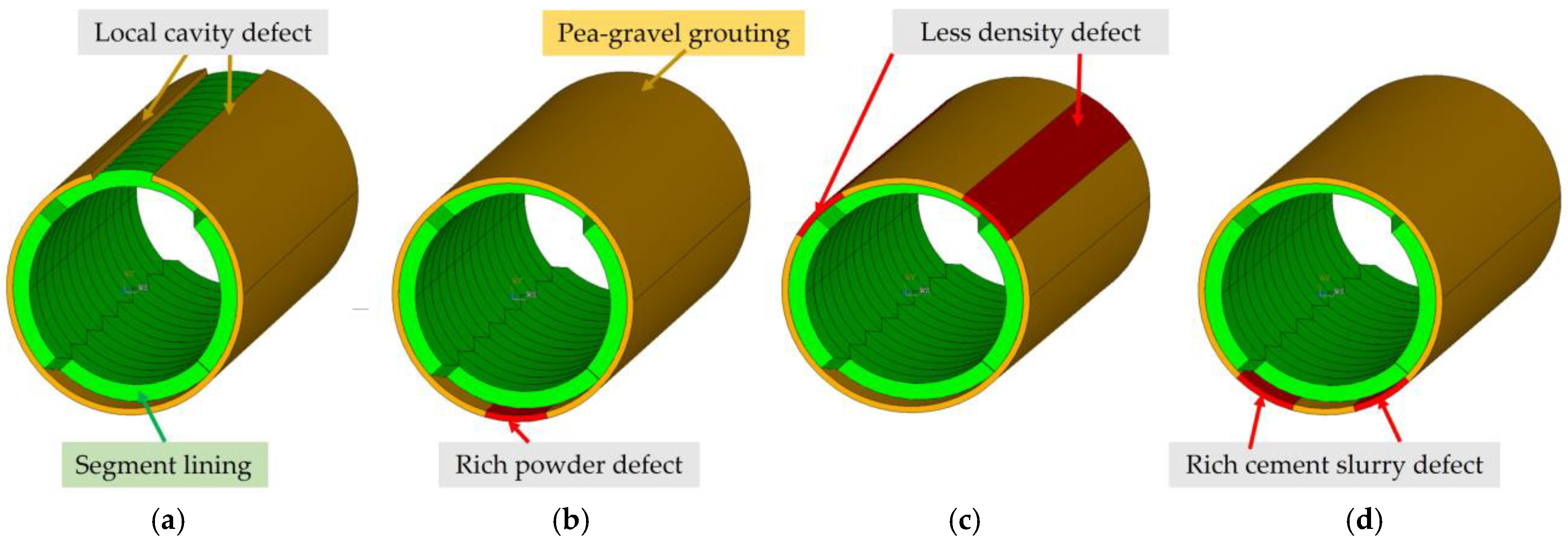
2.3. Cases for Numerical Analysis

In this study, the geological transition zones between different classes of surrounding rocks were labeled as V–IV, V–III and IV–III. As listed in Table 4, in combining four types of pea-gravel grouting defects with a central angle of 30° and comparing them with the tunnel with intact pea-gravel grouting, fifteen cases were calculated for the numerical analysis with the 3D FEM.
In the numerical calculations, the self-weight of segments and pea-gravel grouting, the external pressure of surrounding rock and the internal free delivery water with 1.3 m deep were exerted on the 3D FEM. Additionally, based on the detection and considered embedded depth of the tunnel, a vertical pressure was exerted on the top boundary with values of 0.72 MPa, 0.65 MPa and 0.56 MPa for classes III, IV and V surrounding rocks, respectively.

2.4. Verification of Numerical Models

To verify the results of numerical models, the model with intact pea-gravel grouting was first analyzed. Detailed graphical expressions of the displacement and circumferential stress are presented in the following sections to better exhibit the difference in the numerical results of the models with or without pea-gravel grouting defects.
Generally, for the numerical models without pea-gravel grouting defects, the vertical displacement almost linearly decreased from top to bottom, with the maximum at the top segment, and the horizontal displacement reaching the maximum at both sides, whatever the segment lining was in the transition zones of V–IV, V–III or IV–III surrounding rocks. The maximum horizontal displacement was 1.53 mm, 0.56 mm and 0.51 mm, while the maximum vertical displacement was 3.65 mm, 2.95 mm and 2.62 mm. This shows a decrease in the deformation of segment lining with the increased self-supporting capacity of better surrounding rocks [6,13,43].
In the transition zone of V–IV surrounding rocks, the inner surface of segment lining presented a tensile stress with a maximum of 0.79 MPa and 0.83 MPa on the top and bottom, and a compressive stress on the web sides. Correspondingly, the outer surface of segment lining had compressive stress on the top and bottom, and tensile stress with a maximum of 0.69 MPa on the web sides.
In the transition zone of V–III surrounding rocks, the inner surface of segment lining presented a tensile stress with a maximum of 0.75 MPa and 0.77 MPa on the top and bottom, and compressive stress on the web sides. Correspondingly, the outer surface of segment lining presented compressive stress on the top and bottom, and tensile stress with a maximum of 0.63 MPa on the web sides.
In the transition zone of IV–III surrounding rocks, the inner surface of segment lining had tensile stress with the maximum of 0.51 MPa and 0.65 MPa on the top and bottom, and compressive stress on the web sides, while the outer surface of the segment lining was all in compression.
Therefore, the stress was similar in distribution on the segment lining under different surrounding rocks and became smaller with better self-support of the surrounding rocks in the order of V–IV, V–III and IV–III.
Compared to those distributions of the displacement and circumferential stress of the segment lining under a single rock condition [11,35,36], the rational regulation obtained in this study demonstrates the reasonability of the built numerical models.

3. Analytical Results and Discussion

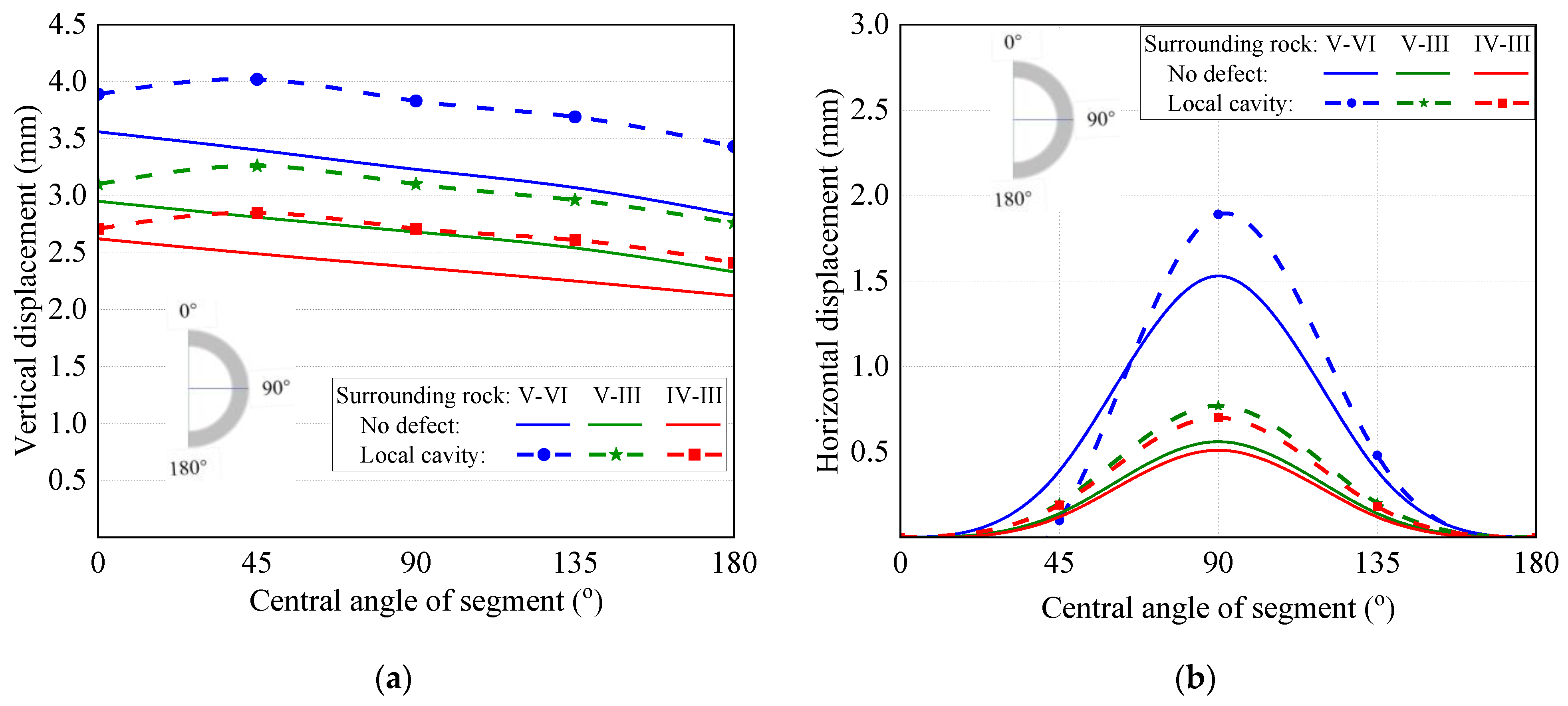
3.1. Effect of Local Cavities on Pea-Gravel Grouting

3.1.1. Displacement of Segment

Figure 3 presents the vertical and horizontal displacements of segments in the case of a local cavity defect of pea-gravel grouting, compared with those of segments with intact pea-gravel grouting. At transition zones of V–IV, V–III and IV–III surrounding rocks, the local cavities of pea-gravel grouting led to enlarged vertical and horizontal displacements of the segment. The vertical displacement continued to decrease from top to bottom with a maximum of 4.02 mm, 3.26 mm and 2.85 mm at the top segment, while the horizontal displacement still increased from top and bottom to the web with maximum values of 1.89 mm, 0.77 mm and 0.70 mm. Comparatively, because the integrity and stiffness of rocks became weak as the rock class changed from III to V, the vertical and horizontal displacements of segments exhibited a correspondingly marked response resulting from the local cavity defect. The segment at the transition zone of V–IV surrounding rocks has an increase of 10.9–21.2% in vertical displacement and 23.5–37.5% in horizontal displacements, while the horizontal displacement sharply decreases from the top to the sides due to the local cavities weakening the stiffness of adjacent segment lining.

3.1.2. Circumferential Stress of Segment

Figure 4 presents the circumferential stress variations in segments in the case of a local cavity defect of pea-gravel grouting, compared with those of segments with intact pea-gravel grouting. At the transition zones of V–IV, V–III and IV–III surrounding rocks, the local cavities of pea-gravel grouting converted tension to compression of circumferential stress on the upper half ring of segment lining, leading to the tensile stress on the inner surface moving from the top to both sides corresponding to the local cavities. Meanwhile, the top inner surface turned from tension to compression, and the top outer surface turned from compression to tension. This is attributed to the squeezing action of surrounding rock pressure along the horizontal direction, eliciting the deformation conversion of the top segment under less vertical pressure, transferred from surrounding rock by the pea-gravel grouting with a local cavity defect.
At the same time, the tensile stress on the inner surface of segment increased by 13.9%, 16.0% and 49.0% at the transition zones of V–IV, V–III and IV–III surrounding rocks. In addition, the bottom of segment lining had a decrease in tensile stress at the transition zone of V–IV surrounding rocks, which turned out to be compression at V–III and IV–III surrounding rocks.
In view of the web of the segment lining under V–IV surrounding rocks, the outer surface had a tensile stress of 0.81 MPa with an increase of 17.4% compared to that segment lining with intact pea-gravel grouting, while the inner surface had compressive stress of 3.86 MPa with an increase of 15.2%. A notable change happened on the web of the segment under V–III surrounding rocks; the outer surface turned from a tensile stress of 0.63 MPa to compression, while the inner surface underwent some increase in compressive stress. Less change was observed on the web of the segment under IV–III surrounding rocks; the outer surface experienced an increase in compression and the inner surface experienced a decrease in compression. Generally, significant change in surrounding rocks from class V to class III will raise a marked response on the web of the segment lining with a local cavity defect in the pea-gravel grouting.
However, the maximum tensile stresses on the inner and outer surfaces of segment lining were 0.90 MPa and 0.81 MPa, which are lower than the limit of 2.24 MPa. Therefore, the single local cavity defect of pea-gravel grouting will not lead to the cracking of segment concrete.

3.2. Effect of Less Density on Pea-Gravel Grouting

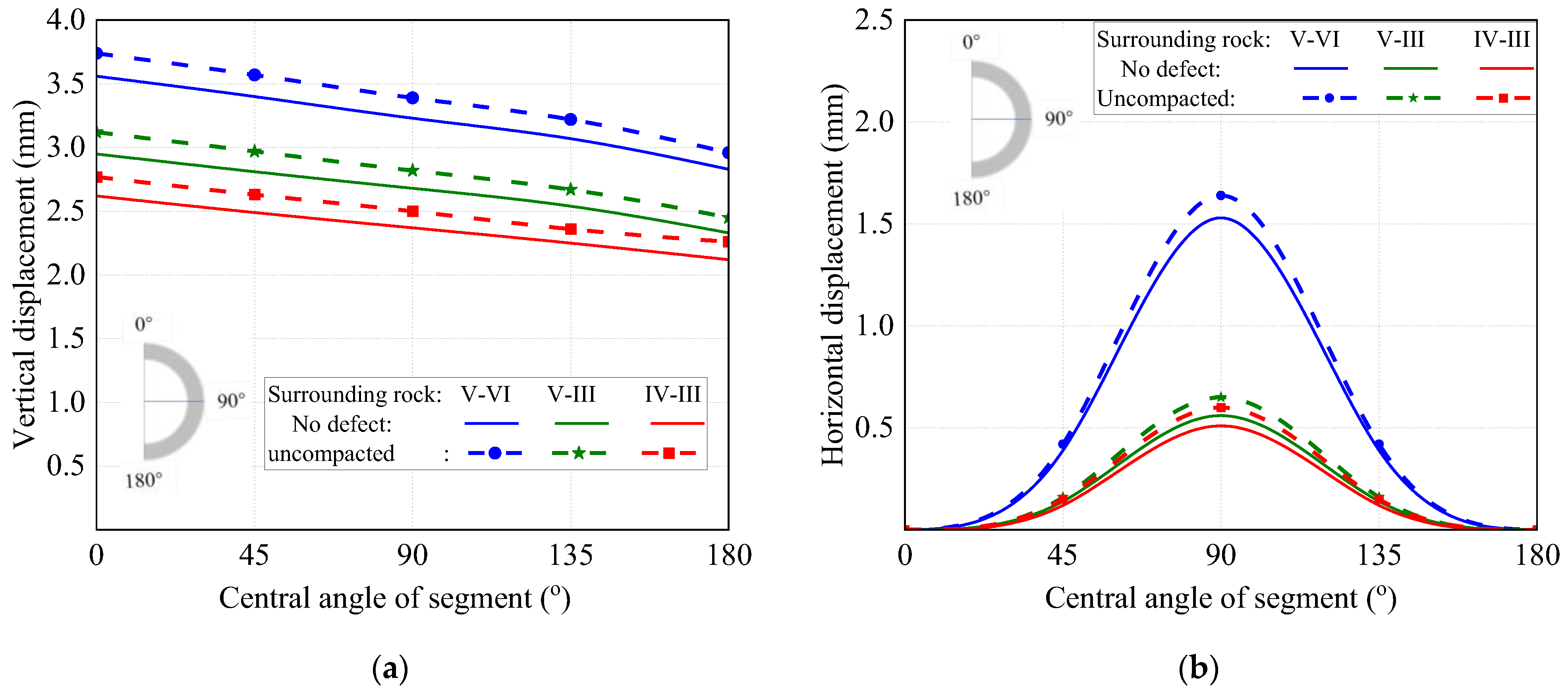
3.2.1. Displacement of Segment

Figure 5 presents the vertical and horizontal displacement variations in segments in the case of the less density defect of pea-gravel grouting, compared with those of segments with intact pea-gravel grouting. Compared with that of segment lining with intact pea-gravel grouting, the displacements of segment lining with the less density defect of pea-gravel grouting have no change in the distribution regularity at the transition zones of V–IV, V–III and IV–III surrounding rocks, except for an increase in values. The maximum vertical displacement appeared at the top of the segment lining with values of 3.74 mm, 3.12 mm and 2.77 mm, respectively, at the transition zones of V–IV, V–III and IV–III surrounding rocks, causing an increase of 5.1%, 5.8% and 5.7%. The maximum horizontal displacement appeared at the web of the segment lining with a value of 1.64 mm, 0.65 mm and 0.60 mm, respectively, at the transition zones of V–IV, V–III and IV–III surrounding rocks, with an increase of 7.1%, 16.1% and 17.6%.

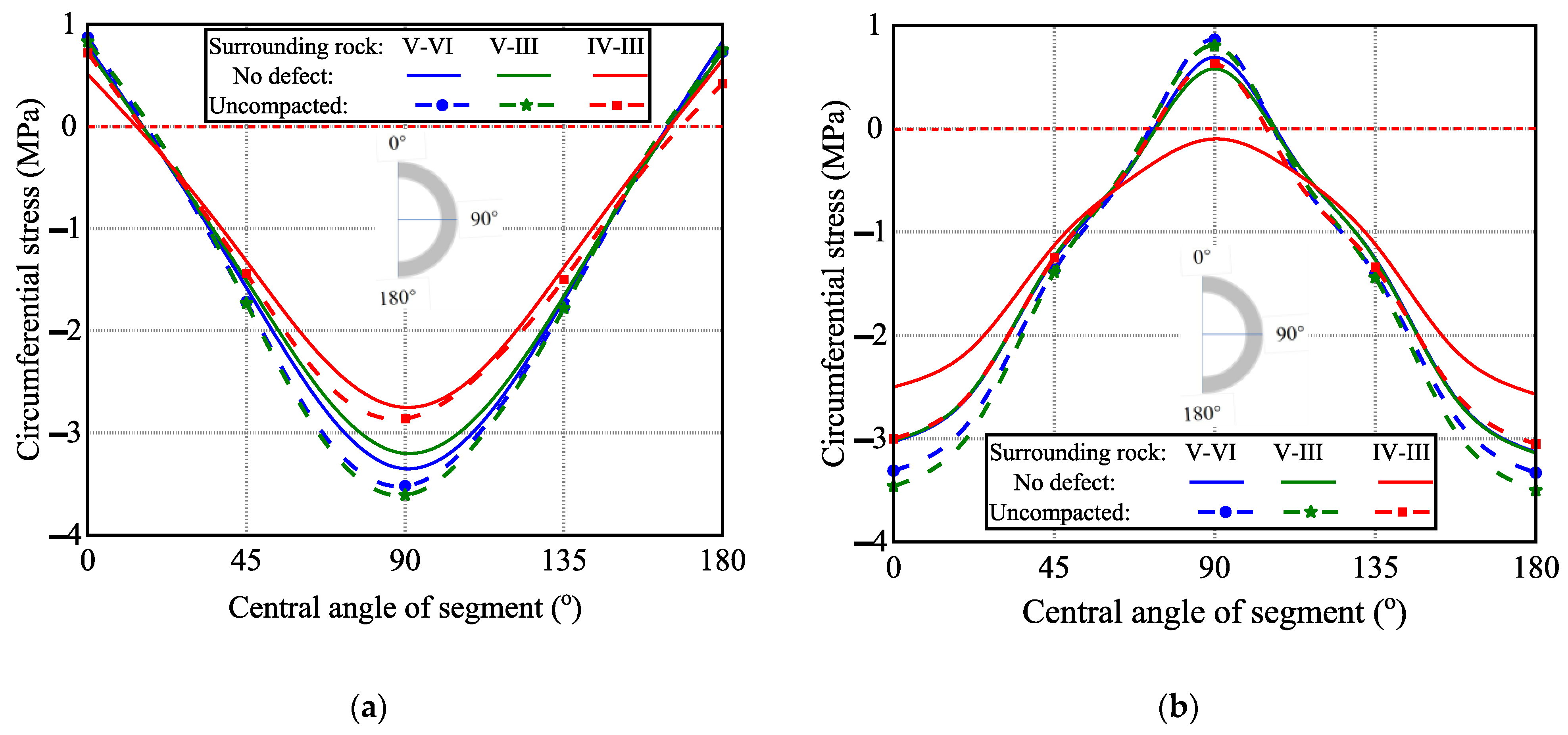
3.2.2. Circumferential Stress of Segment

Figure 6 presents the circumferential stress variations in segments in the case of the less density defect of pea-gravel grouting, compared with those of segments with intact pea-gravel grouting. Compared with that of segment lining with intact pea-gravel grouting, the circumferential stress of segment lining with the less density defect of pea-gravel grouting had no change in the distribution regularity at the transition zones of V–IV, V–III and IV–III surrounding rocks, except for an increase in values. The inner surface of the top and bottom of the segment lining was still in tension with a maximum tensile stress of 0.87 MPa, 0.83 MPa and 0.72 MPa under V–IV, V–III and IV–III surrounding rocks, leading to an increase of 10.1%, 10.7% and 41.2%, respectively. Meanwhile, the outer surface of the top and bottom of the segment lining underwent higher compression.
The inner surface of the web of the segment lining was still in compression with increased stress, while the outer surface of the web came into tension with maximum stress of 0.86 MPa, 0.80 MPa and 0.63 MPa, leading to an increase of 24.6% and 37.9% at V–IV and V–III surrounding rocks, and the compression transferred to tension at IV-III surrounding rocks.
Generally, the less density defect of pea-gravel grouting led to the increase in tensile and compressive stresses, even causing the web of the segment lining to transfer from compression to tension. However, the maximum tensile stress was within 0.87 MPa, which is lower than the limit of 2.24 MPa.

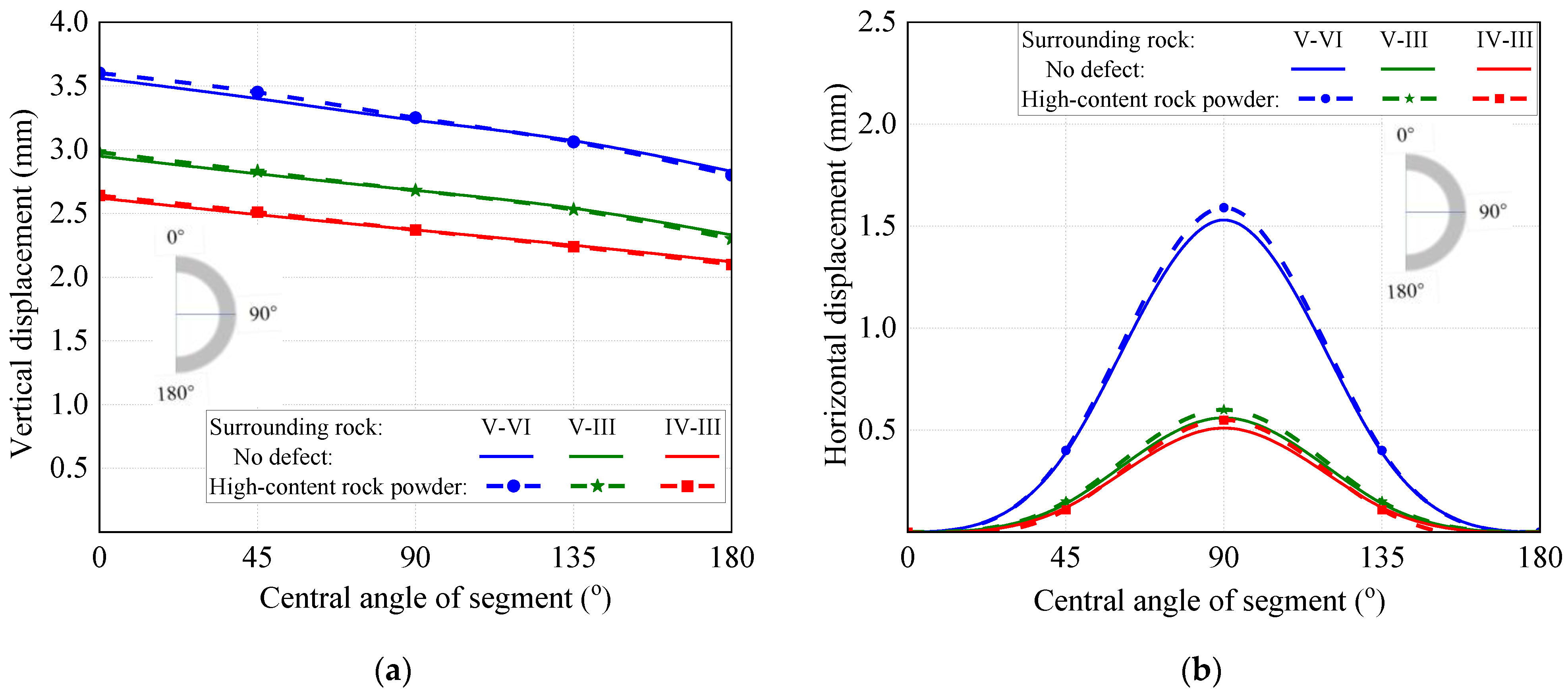
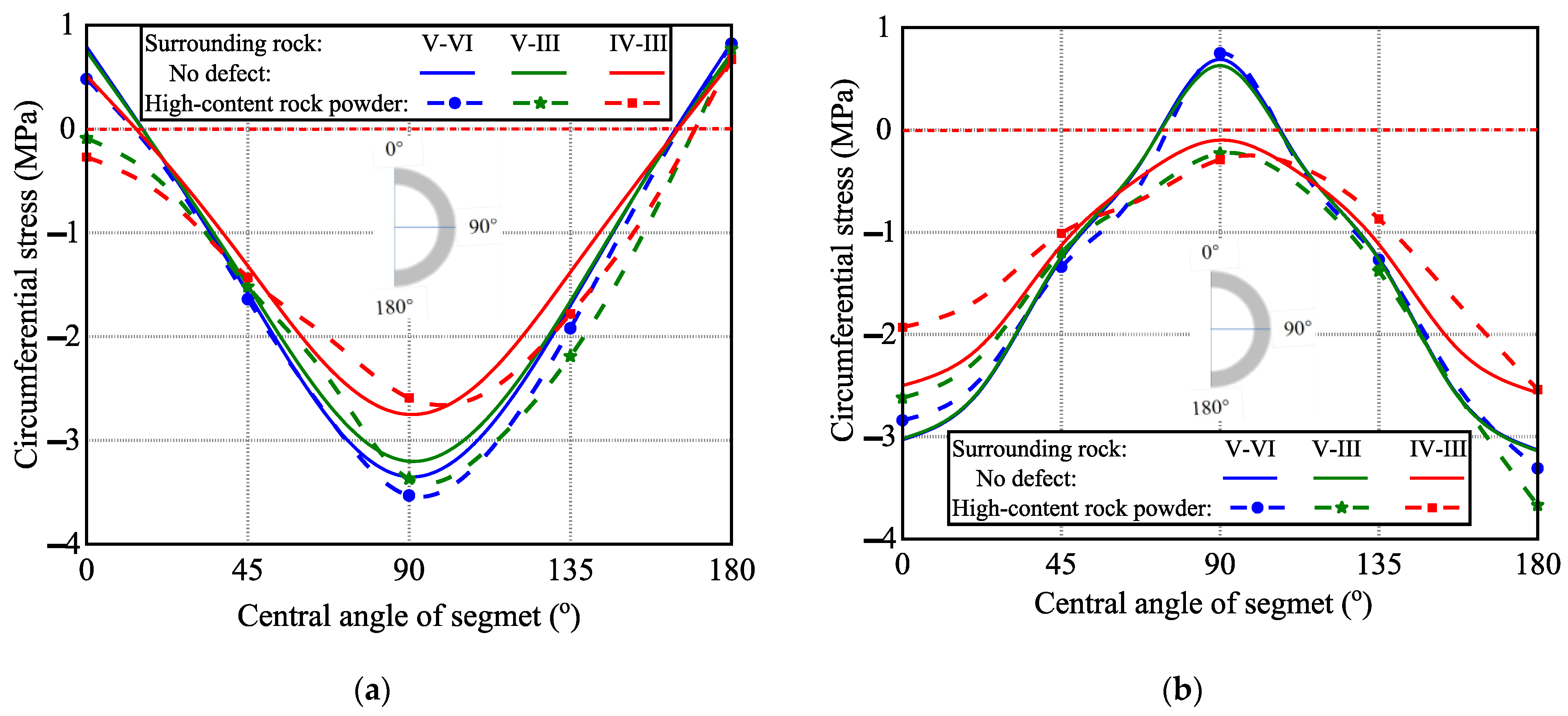
3.3. Effect of Rich Rock Powder on Pea-Gravel Grouting

3.3.1. Displacement of Segment

Figure 7 presents the vertical and horizontal displacement variations in segments in the case of the rich rock powder defect of pea-gravel grouting, compared with those of segments with intact pea-gravel grouting at the transition zones of V–IV, V–III and IV–III surrounding rocks. Compared with that of segment lining with intact pea-gravel grouting, the vertical displacements were almost the same with slight change under the same surrounding rocks with rich rock powder defect and presented a decreasing tendency from the top to bottom of the segment lining. Meanwhile, the horizontal displacements of segment lining with the rich rock powder defect of pea-gravel grouting also have no effect on the distribution regularity, except for that the maximum at the web of the segment lining increased by 3.9%, 7.1% and 7.8%, respectively, at the transition zones of V–IV, V–III and IV–III surrounding rocks.

3.3.2. Circumferential Stress of Segment

Figure 8 presents the circumferential stress variations in segments in the case of the rich rock powder defect of pea-gravel grouting, compared with those of segments with intact pea-gravel grouting at the transition zones of V–IV, V–III and IV–III surrounding rocks. Comparatively, regarding the decrease in compressive stress on the outer surface of the top of segment lining, a decrease in tensile stress appeared on the inner surface at the three classes of surrounding rocks, and even underwent compression at V–III and IV–III surrounding rocks. Meanwhile, the inner surface of the bottom of segment lining remained steadily under tensile stress at the same surrounding rock. The web of segment lining was in compression at IV–III surrounding rocks, transferred from tension to compression at V–III surrounding rocks, and kept a maximum tensile stress of 0.82 MPa at V–IV surrounding rocks. This indicates that an obvious change in circumferential stress happened on the segment lining at V–III surrounding rocks due to the notable variation in rock class.

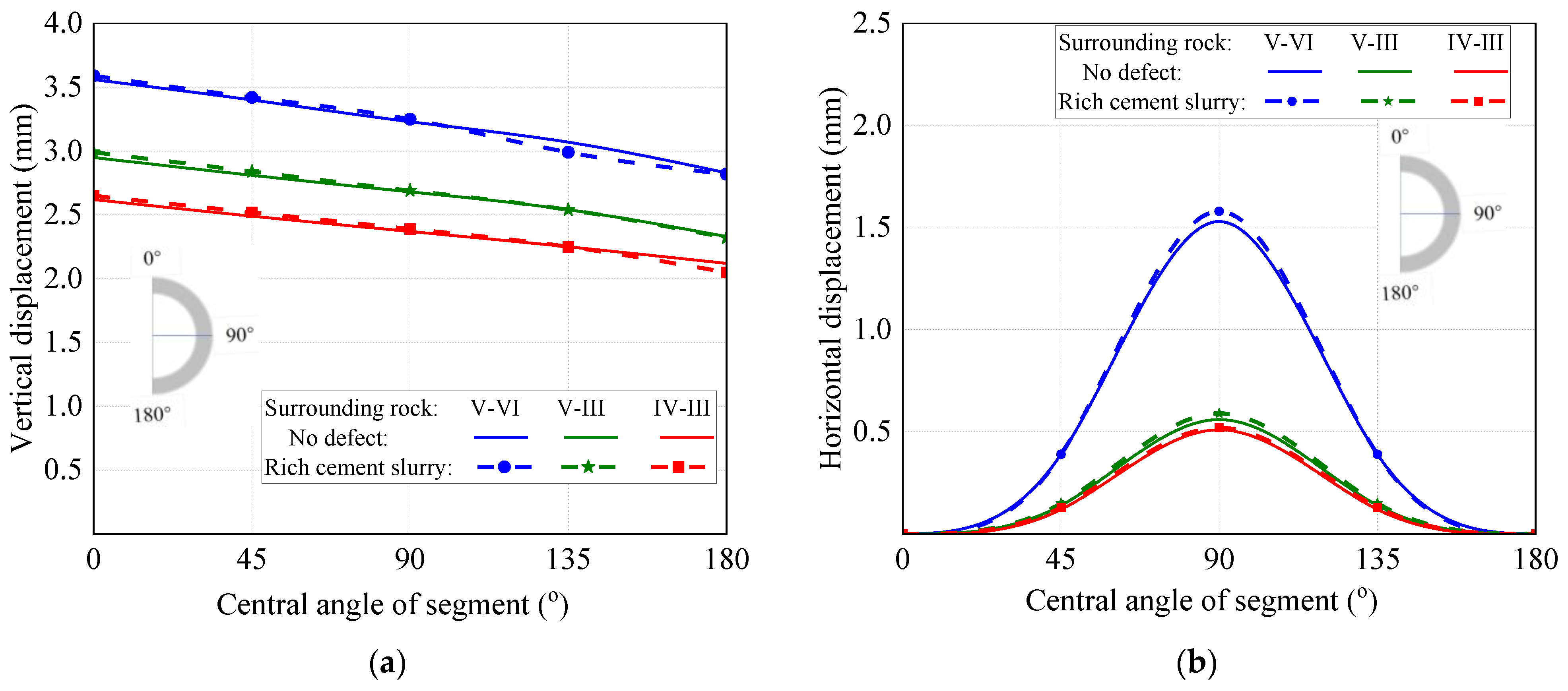
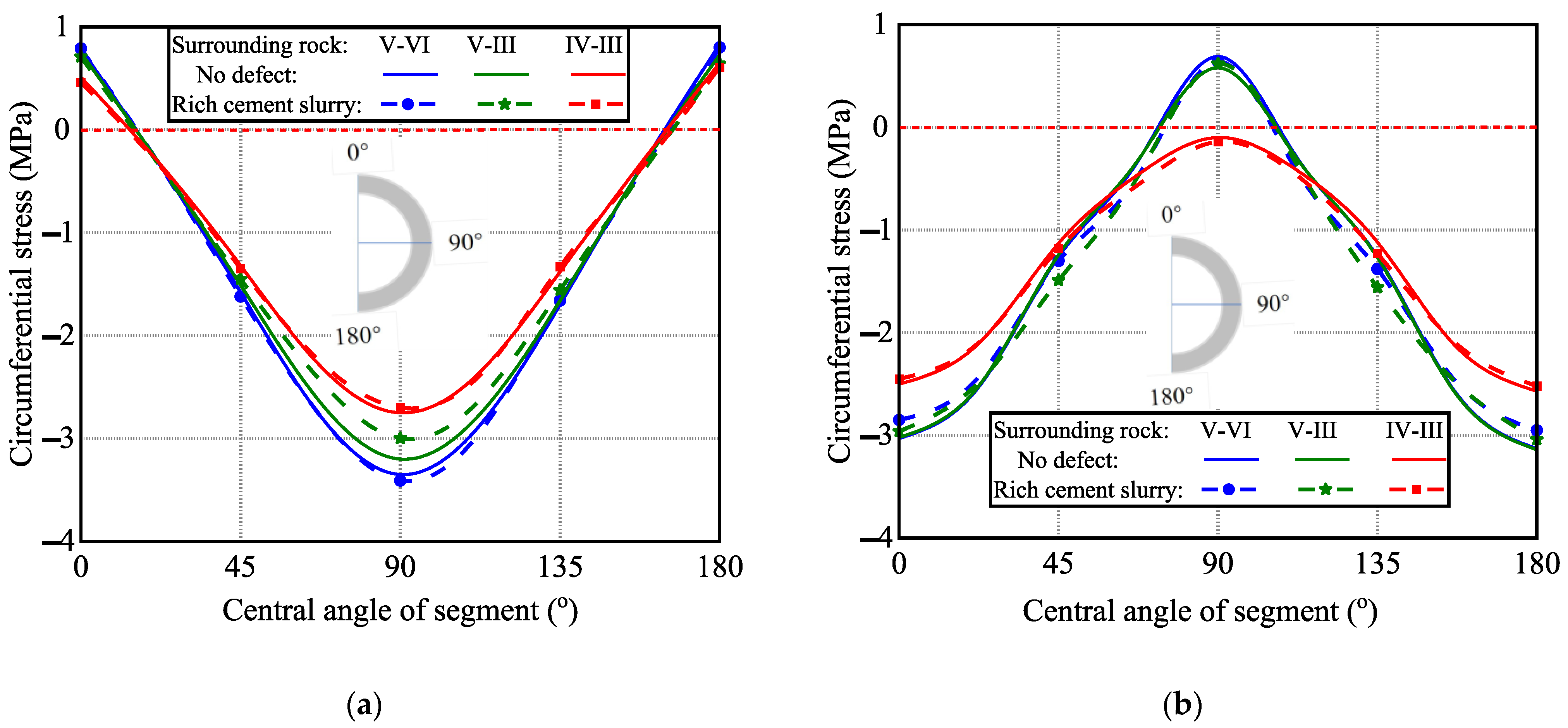
3.4. Effect of Rich Cement Slurry on Pea-Gravel Grouting

3.4.1. Displacement of Segment

Figure 9 presents the vertical and horizontal displacement variations in segments in the case of the rich cement slurry defect of pea-gravel grouting, compared with those of segments with intact pea-gravel grouting. A slight change presented in the vertical displacement, with a lower increase in horizontal displacement for the segment lining at the same class of surrounding rocks of V–IV, V–III and IV–III, respectively. The vertical and horizontal displacements were 3.59 mm and 1.58 mm at the maximum at the top and web of the segment lining with V–IV surrounding rocks.

3.4.2. Circumferential Stress of Segment

Figure 10 presents the circumferential stress variations in segments in the case of the rich cement slurry defect of pea-gravel grouting, compared with those of segments with intact pea-gravel grouting. At the transition zone of V–IV, V–III and IV–III surrounding rocks, the inner surface at the top and bottom of the segment lining slightly decreased in tensile stress, and the outer surface of the web of segment lining steadily remained under tensile or compressive stress. The circumferential tensile stress reached the maximum of 0.80 MPa at the bottom of the segment lining with V–IV surrounding rocks.

3.5. General Discussion

In engineering projects, the defects of pea-gravel grouting are random and may be combined with others. Therefore, based on the numerical analysis of the effect of each single defect on the loading response of segment lining, the maximum stresses on the inner and outer surfaces of segment lining were analyzed with different defect combinations in the transition zone of IV–III, V–III and V–IV surrounding rocks. It is assumed that the stresses for the defect combination can be summed directly, considering that the segment concrete worked at the elastic phase [38].
In all combination conditions, the stress distribution of segment lining became worse with large difference when the surrounding rock varied in the order of IV–III, V–III and V–IV. The maximum compressive stress of 14.32 MPa appeared on the inner surface of segment lining with a central angle of 90° in the transition zone of V–IV surrounding rocks, which was safe at a level of 44.2% compressive strength of concrete. Fortunately, although the maximum tensile stresses of segment lining increased with the combination of two defects of pea-gravel grouting, the maximum value of 1.67 MPa is much less than the limit of 2.24 MPa, which shows a safe segment lining. Meanwhile, the maximum tensile stress was 1.70 MPa for the segment lining in the transition zone of VI–III surrounding rocks with three or all four defects. This means that segment linings at VI–III surrounding rocks under all conditions of defect combinations are safe without worrying about concrete cracking, like segment lining under V–III and V–IV surrounding rocks under the conditions of two-defect combinations.
The possible cracking of segment concrete existed in the transition zones of V–III and V–IV surrounding rocks, when three defects or all four defects presented in the pea-gravel grouting. For the segment lining in the transition zone of V–III surrounding rocks, the combination of defects including less density, rich rock powder and rich cement slurry led to a maximum tensile stress of 2.16 MPa on the inner surface of the bottom, very closing to the limit of 2.24 MPa. For the segment lining in the transition zone of V–IV surrounding rocks, the combination of three defects or all four defects led to a maximum tensile stress of 2.09–2.91 MPa on the inner surface of the bottom, and a maximum tensile stress of 2.25–3.06 MPa on the outer surface of the web sides, basically over the limit of 2.24 MPa.

4. Conclusions

Combined with the engineering project of a water delivery TBM tunnel, 3D FEM models were built comprising segment lining, pea-gravel grouting and surrounding rock. Reasonable detailed constructions were simplified for locating pins, contacted surfaces and connected slots. Numerical analyses were carried out to study the effects of pea-gravel grouting defects on the loading response of segment lining, where the pea-gravel grouting defects were local cavities, less density, rich rock powder and rich cement slurry. The numerical analytical section of the models was set at the transition zone of different classes of surrounding rocks, labeled V–IV, V–III and IV–III. The following results can be concluded:
(1)
The vertical and horizontal displacements of segment lining maintain similar regulation for the segment lining with or without pea-gravel grouting defects. The vertical displacement of segment lining decreases from top to bottom, and the horizontal displacement increases from top or bottom to the web. The local cavities have a comparatively large effect with an increase of 10.9–21.2% vertical displacement and 23.5–37.5 horizontal displacement. The other three types of defects have less influence on the displacement of segment lining.
(2)
The local cavities of pea-gravel grouting convert the tensile and compression of circumferential stress on the upper half ring of segment lining, leading to the greatest effect on the stress distribution. The other three types of pea-gravel grouting defects have a comparatively lower effect on the stress distribution except for on changing stress values. The defect effects on the loading response of segment lining become stronger with the weaker self-support of surrounding rocks in the order of IV–III, V–III and V–IV, which results in relatively larger effects on the maximum tensile stress of segment lining at V–IV surrounding rocks.
(3)
With the combinations of all four defects, the segment lining is safe in compression with a maximum of only 44.2% compressive strength of concrete. Depending on the better self-support of IV–III surrounding rocks, segment lining under the combination of all four defects is safe without worrying about cracking, because the maximum tensile stress is within the limit. Cracking is possible on the inner bottom surface of segment concrete with a combination of defects, including less density, rich rock powder and rich cement slurry in the transition zone of V–III surrounding rocks, due to the maximum tensile stress being very close to the limit. For the segment lining in the transition zone of V–IV surrounding rocks, the most possible cracking exists on the inner bottom surface and the outer surface of the web sides with the combination of three defects or all four defects, due to the maximum tensile stresses being basically over the limit.
(4)
The results of this study show that the inner surface of the top and bottom, and the outer surface of the web sides of segment lining face the risk of concrete cracking. This can be referenced to determine the key positions of quality inspection for pea-gravel grouting in TBM tunnel construction and operation.
(5)
This study was limited to a tunnel for non-pressurized water delivery with an inner diameter of 3.5 m, with more limitations observed in the modeling approaches for geometry simplifications, material properties, and loading cases to confine the wide application of the results. Therefore, further studies on TBM tunnels under other conditions for water delivery should be continuously conducted, and should be combined with experimental or real-world measurements.

Author Contributions

Conceptualization, S.Z. and Q.C.; methodology, C.L. and Z.Z.; formal analysis and investigation, X.W. and Y.H.; writing—original draft preparation, X.W., Y.H. and Z.Z.; writing—review and editing, C.L. and Q.C.; supervision and funding acquisition, S.Z. All authors have read and agreed to the published version of the manuscript.

Funding

This study was financially supported by the Fund for First-class Discipline Innovation Team of Henan, China (grant No. CXTDPY-6), and the New Round of Key Disciplines of Henan, China (grant No. JY2023-414-349).

Institutional Review Board Statement

Not applicable.

Informed Consent Statement

Not applicable.

Data Availability Statement

The data presented in this study are available on request from the corresponding author.

Conflicts of Interest

Authors Qixing Che, Zhixiao Zhang and Yintao He are employed by the Zhongzhou Water Supply Holding Company Limited. The remaining authors declare that the research was conducted in the absence of any commercial or financial relationships that could be construed as a potential conflict of interest.

References

  1. Qu, S.; Huang, H.; Gao, Z. Planning on water diversion project for central area of Yunnan Province. Yangtze River 2013, 44, 80–83. [Google Scholar]
  2. Qi, Z.; He, F. Application of sliding-type open TBM stepping technology to Songhua River Water Diversion Project. Tunn. Constr. 2017, 37, 184–188. [Google Scholar]
  3. Lu, A.; Xiao, H.; Shen, X.; Fu, Y. Design and construction technology of slurry shield used in Shiziyang water conveyance tunnel. Mod. Tunn. Technol. 2020, 57, 226–231. [Google Scholar]
  4. Wang, L.; Lin, Q.; Zhao, J. Brief introductions on overall layout of the River Diversion Project from the Yangtze River to the Han River. Chin. Water Resour. 2022, 19, 36–39. [Google Scholar]
  5. GB/T 51438-2021; Standard for Design of Shield Tunnel Engineering. China Building Industry Press: Beijing, China, 2021.
  6. Dong, L.; Yang, Z.; Wang, Z.; Ding, Y.; Qi, W. Study on internal force of tunnel segment by considering the influence of joints. Adv. Mater. Sci. Eng. 2020, 3, 1–13. [Google Scholar] [CrossRef]
  7. Mo, J.; Tang, X.; Yan, Z. Load bearing and deformation characteristics of single-layer segment lining structure for water conveyance tunnels. Chin. J. Geotech. Eng. 2023, 45, 1365–1373. [Google Scholar]
  8. Zhao, X.; Han, K.; Ju, J.; Chen, X.; Chen, W.; Xiong, H. Numerical analysis of size effect on the deformation behavior and damage evolution mechanism of segmental tunnel lining rings. Int. J. Damage Mech. 2023, 32, 600–622. [Google Scholar] [CrossRef]
  9. Zhang, Z.; Wang, B.; Wang, X.; He, Y.; Wang, H.; Zhao, S. Safety risk assessment of TBM tunnel construction based on fuzzy evidence reasoning. Processes 2022, 10, 2597. [Google Scholar] [CrossRef]
  10. Li, F.; Si, P.; He, Y.; Wang, H.; Zhang, Z. Case studies of the load-bearing performance of shield tunnel segment with misaligned defects. Sci. Rep. 2024, 14, 17370. [Google Scholar] [CrossRef] [PubMed]
  11. Si, P.; Li, C.; Wang, X.; He, Y.; Che, Q.; Zhao, S. A case study of systemic risk assessment for the operational safety of a long-distance water delivery tunnel. Processes 2025, 13, 1677. [Google Scholar] [CrossRef]
  12. Hu, M. Study on Mechanical Effect of Pea-gravel Backfill Grout Layer in TBM Tunnel Lining System. Master’s Thesis, Chengdu University of Technology, Chengdu, China, 2019. [Google Scholar]
  13. GB50446-2017; Code for Construction and Acceptance of Shield Tunnelling Method. China Building Industry Press: Beijing, China, 2017.
  14. Luo, J.; Peng, L. Pea-stone backfilling and quality control in TBM construction. Hunan Water Resour. Hydropower 2018, 63, 37–40. [Google Scholar]
  15. Han, W.; Wang, X. Study on the optimum grouting materials and their performance in the TBM tunnel collapse reinforcement project. IOP Confer. Ser. Earth Environ. Sci. 2020, 570, 052065. [Google Scholar]
  16. Liang, X.; Ying, K.; Ye, F.; Su, E.; Xia, T.; Han, X. Selection of backfill grouting materials and ratios for shield tunnel considering stratum suitability. Constr. Build. Mater. 2022, 314, 125431. [Google Scholar] [CrossRef]
  17. Jiang, B.; Wu, M.; Wu, S.; Zheng, A.; He, S. A review on development of industrial solid waste in tunnel grouting materials: Feasibility, performance, and prospects. Materials 2023, 16, 6848. [Google Scholar] [CrossRef] [PubMed]
  18. Hu, C.; Guo, J.; Wang, Z. Lattice Boltzmann simulation for grout filling process during simultaneous backfill grouting of shield in tunnel construction. Euro. J. Environ. Civ. Eng. 2022, 26, 4039–4054. [Google Scholar] [CrossRef]
  19. Qin, N.; Ye, F.; He, B.; Liang, X.; Han, X.; Su, E. Model study on backfill grouting in shield tunnels based on fractal theory. Euro. J. Environ. Civ. Eng. 2022, 26, 5901–5911. [Google Scholar] [CrossRef]
  20. Su, S.; Cheng, B.; Sun, W.; Zhang, J. Preliminary design for pea-gravel grouting in TBM tunnelling. Chin. J. Rock. Mechan. Eng. 2001, 20, 208–211. [Google Scholar]
  21. Liu, L. Pea-gravel backfilling grouting technology of TBM construction. Water Resour. Hydropower Eng. 2012, 43, 63–66. [Google Scholar]
  22. Wu, S.; Zhao, H.; Xie, H.; Dong, Y.; Fang, L.; Wang, M.; Liu, Y. Distribution characteristics of pea gravel behind segment in shield tunnel boring Machine tunnels. Adv. Eng. Sci. 2023, 56, 150–160. [Google Scholar]
  23. Yang, F.; Jin, J.; Yang, F. Influence of backfill grouting property and compactness of TBM pea-gravel on supporting effect. Yellow River 2024, 46, 139–145. [Google Scholar]
  24. Zhang, J.; Huang, Q.; Wang, X.; Hu, C.; Zhang, S. The engineering influence of pea gravel annulus grouting layer with defects. Morden Tunn. Tech. 2021, 58, 163–172. [Google Scholar]
  25. Wang, M.; Hou, S.; Liu, Y.; Jin, F. Influence of backfill grouting compactness in TBM pea-gravel on supporting effect. Tunn. Constr. 2020, 40, 326–336. [Google Scholar]
  26. Zheng, R. Design and construction of pea-gravel grouting for No.1 tunnel in north route of Wanjiazhai Yellow River Diversion Project. Water Resour. Hydropower Eng. 2007, 38, 39–40. [Google Scholar]
  27. Fan, C. Analysis on key points to control engineering quality of tunnel constructed by TBM in Tao River Delivery Project and the countermeasure. Shanxi Hydrotech. 2008, 3, 64–65. [Google Scholar]
  28. Henzinger, M.R.; Pejic, D.; Schubert, W. Design improvements of segmental linings due to unfavorable bedding situations. Procedia Eng. 2017, 191, 729–734. [Google Scholar] [CrossRef]
  29. SL 279-2016; Specification for Design of Hydraulic Tunnel. China HydroPower Press: Beijing, China, 2016.
  30. SL 191-2008; Design Code for Hydraulic Concrete Structures. China HydroPower Press: Beijing, China, 2008.
  31. Shang, P.; Qu, F.; Wang, J.; Geng, Y.; Yan, T.; Zhao, S. A Simplified limit-state design and verification for prestressed concrete cylinder pipes under internal water pressure. Buildings 2023, 13, 2825. [Google Scholar] [CrossRef]
  32. Qu, F.; Zhang, D.; Wang, H.; Zheng, W.; Zhao, S. Full-scale test and bearing capacity evaluation of large diameter prestressed concrete cylinder pipe under internal water pressure. Buildings 2022, 12, 1791. [Google Scholar] [CrossRef]
  33. Sun, W.; Li, X.; Cheng, K.; Jia, W.; Liu, H. Analysis on the influence of large diameter intercity railway tunnel under passing the main canal of the middle route of South-to-North Water Diversion Project. J. North China Univ. Water Resou. Electr. Power (Nat. Sci. Ed.) 2020, 41, 46–52. [Google Scholar]
  34. Chen, Z.; Li, X.; Yang, Y.; Zhao, S.; Fu, Z. Experimental and numerical investigation of the effect of temperature patterns on behaviour of large scale silo. Eng. Fail. Anal. 2018, 91, 543–553. [Google Scholar] [CrossRef]
  35. Zhang, Y.; Li, X.; Xue, G.; Yao, G.; Chen, Z.; Zhao, S. Mechanical performance of the prestressed concrete lining withstanding prestress of steel strands: Full-scale test and numerical simulation. Alex. Eng. J. 2025, 114, 621–635. [Google Scholar] [CrossRef]
  36. Li, F.; Si, P.; He, Y.; Wang, H.; Zhang, Z.; Zhao, S. Numerical analysis of the single-directionally misaligned segment behavior of hydraulic TBM tunnel. Buildings 2024, 14, 2198. [Google Scholar] [CrossRef]
  37. Zhao, S.; Cui, H.; He, Y.; Yang, Y.; Zhang, Z.; Yuan, L. Bearing performance of shield tunnel lining segments affected by softened base due to internal water leakage. J. Water Resour. Water Eng. 2024, 35, 201–206. [Google Scholar]
  38. He, Y.; Li, C.; Wang, X.; Che, Q.; Wang, L.; Zhao, S. Case study of the impacts of pea-gravel grouting defects on loading responses of TBM tunnel segment lining with different surrounding rocks. Result. Eng. 2025, 27, 105807. [Google Scholar] [CrossRef]
  39. Cao, Y.; Wang, P.; Jin, X.; Wang, J.; Yang, Y. Tunnel structure analysis using the multi-scale modeling method. Tunn. Undergr. Space Technol. 2012, 28, 124–134. [Google Scholar] [CrossRef]
  40. Wang, X. ANSYS Engineering Structures Numerical Analysis; China Communications Press: Beijing, China, 2007. [Google Scholar]
  41. GB 50010-2010; Code for Design of Concrete Structures (2024 Ed.). China Building Industry Press: Beijing, China, 2024.
  42. SL 62-2014; Technical Specifications for Cement Grouting of Hydraulic Structures. China Hydropower Press: Beijing, China, 2014.
  43. GB 50218-94; Standard for Engineering Classification of Rock Masses. China Building Industry Press: Beijing, China, 1994.
  44. Wang, Y.; Li, X.; Cao, R.; Xu, Z.; Chen, B.; Zhang, X. Study on classification of surrounding rock suitable for TBM construction of hydraulic tunnel. J. Hydraul. Eng. 2023, 54, 880–888. [Google Scholar]
Figure 1. Three-dimensional FEM numerical model of TBM tunnel structure: (a) overview; (b) longitudinal section.
Eng 06 00166 g001
Figure 2. Pea-gravel grouting defects, back of segment lining: (a) local cavities at the top; (b) rich powder at the bottom; (c) less density at the sides of the top; (d) rich cement slurry at the sides of the bottom.
Eng 06 00166 g002
Figure 3. Displacements of segments in case of pea-gravel grouting with local cavity defect: (a)vertical displacement; (b) horizontal displacement.
Eng 06 00166 g003
Figure 4. Circumferential stress of segments in case of pea-gravel grouting with local cavity defect: (a) inner surface; (b) outer surface.
Eng 06 00166 g004
Figure 5. Vertical and horizontal displacement of segments in case of pea-gravel grouting with less density defect: (a) vertical displacement; (b) horizontal displacement.
Eng 06 00166 g005
Figure 6. Circumferential stress of segments in case of pea-gravel grouting with less density defect: (a) inner surface; (b) outer surface.
Eng 06 00166 g006
Figure 7. Vertical and horizontal displacement of segments in case of pea-gravel grouting with rich rock powder defect: (a) vertical displacement; (b) horizontal displacement.
Eng 06 00166 g007
Figure 8. Circumferential stress of segments in case of pea-gravel grouting with rich rock powder defect: (a) inner surface; (b) outer surface.
Eng 06 00166 g008
Figure 9. Vertical and horizontal displacement of segments in case of pea-gravel grouting with rich rock cement slurry defect: (a) vertical displacement; (b) horizontal displacement.
Eng 06 00166 g009
Figure 10. Circumferential stress of segments in case of pea-gravel grouting with rich cement slurry defect: (a) inner surface; (b) outer surface.
Eng 06 00166 g010
Table 1. Physical and mechanical parameters of segment concrete.
Modulus of Elasticity (GPa)Poisson’s Ratio μDensity (kg/m3)Axial Compression Strength (MPa)Tensile Strength (MPa)Shear Modulus (GPa)
350.2250032.42.6413.8
Table 2. Physical and mechanical parameters of pea-gravel grouting with or without defects.
Pea-Gravel GroutingDensity (kg/m3)Modulus of Elasticity (GPa)Poisson’s Ratio μCohesive Force c (MPa)Internal Fraction Angle ϕ (°)
complete20003.250.26
less density14860.65-0.01617
rich rock powder17571.80-2.030
rich cement slurry12462.56-0.542
Table 3. Main physical and mechanical parameters of various surrounding rocks.
Surrounding Rock ClassInternal Fraction Angle ϕ (°)Cohesive Force c (MPa)Deformation Modulus E0 (GPa)Poisson’s Ratio μDensity (kg/m3)Elastic Resistance Coefficient k0 (MPa/cm)
III360.707.00.2724508.0
IV300.102.00.3221502.0
V200.080.50.4018500.3
Table 4. Cases for numerical analysis.
CaseDefectClass of Surrounding Rocks
V–IVV–IIIIV–III
1~3
4~6Local cavities
7~9Less density
10~12Rich rock powder
13~15Rich cement slurry
Disclaimer/Publisher’s Note: The statements, opinions and data contained in all publications are solely those of the individual author(s) and contributor(s) and not of MDPI and/or the editor(s). MDPI and/or the editor(s) disclaim responsibility for any injury to people or property resulting from any ideas, methods, instructions or products referred to in the content.

