Article

An Efficient Hydrodynamic Force Calculation Method for Pile Caps with Arbitrary Cross-Sections Under Earthquake Based on Finite Element Method

1
School of Civil Engineering, Southwest Jiaotong University, Chengdu 610031, China
2
China Road & Bridge Corporation, Beijing 100010, China
3
Sichuan Communication Surveying and Design Institute Co., Ltd., Chengdu 610017, China
*
Author to whom correspondence should be addressed.
Eng 2025, 6(7), 167; https://doi.org/10.3390/eng6070167
Submission received: 9 June 2025 / Revised: 13 July 2025 / Accepted: 14 July 2025 / Published: 21 July 2025

Abstract

The pile group-pile cap structure is a key foundation form for deep-water bridges. However, current effective methods for calculating the earthquake-induced hydrodynamic forces on pile caps with arbitrary cross-sections remain insufficient. In this study, the hydrodynamic force is considered as the added mass, and the dynamic equilibrium equations of the isolated pile cap structure (IC model) and the pile group-pile cap structure (PC model) under earthquakes are established, respectively, based on the structural dynamics theory. Correspondingly, the relationships between the hydrodynamic added masses and the fundamental frequencies in the IC model and the PC model are derived, respectively. The fundamental frequencies of the IC model and the PC model are obtained by numerical models built with the ABAQUS (2019) finite element software, and then the added masses on the IC and PC models are calculated accurately. The calculation method proposed in this study avoids the complex fluid–structure interaction problem, which can be applied for the seismic design of deep-water bridge substructures in real practice.

1. Introduction

In recent years, the rapid development of transportation infrastructure has led to the construction of numerous deep-water bridges, with more and more currently under construction. However, the submerged bridge foundations (e.g., pile groups and pile caps shown in Figure 1) experience significant hydrodynamic forces from surrounding water during earthquakes, thus obviously affecting the bridge’s dynamic response and seismic performance [1]. As a critical load-transfer component connecting piles and piers, the hydrodynamic effects on pile caps directly influence the overall structural stability and safety. Studies have demonstrated that the hydrodynamic force can make fundamental frequencies of structures in water reduced, potentially leading to the structural resonance phenomena or localized damage [2,3]. Therefore, the hydrodynamic forces on pile caps should be carefully considered in the seismic design of deep-water bridges, as it is critical for enhancing the earthquake resistance of underwater structures.
Studies on pier hydrodynamic forces have been studied by many scholars in recent years and are primarily based on the potential flow theory or viscous fluid mechanics. Yang et al. proposed calculation methods for hydrodynamic forces on circular and rectangular hollow piers based on the extended Morison equation and the radiation wave theory [4,5]. Zhang et al. developed a numerical fluid–structure interaction method for calculating hydrodynamic forces on piers with complex geometries (including the circular, elliptical, truncated conical, and complex dumbbell-shaped piers) [6]. Yang et al. derived the hydrodynamic force expression for pile groups under earthquakes by theoretical analysis and numerical simulations [7]. Wang et al. investigated the hydrodynamic force characteristics for columns with arbitrary cross-sections and proposed simplified methods for calculating the hydrodynamic forces on hollow elliptical, round-ended, rectangular, and square columns systematically under seismic excitation [8,9]. Qin et al. studied the influence of shape coefficients for circular, rectangular, and elliptical piers on their hydrodynamic forces during earthquakes and compared them with codes from Japanese and American [10]. Based on the radiation wave theory, Du et al. proposed a more accurate simplified calculation formula for hydrodynamic force on circular piers by introducing dimensionless parameters such as frequency ratio, width-depth ratio, and relative height [11]. Although the studies on pier hydrodynamic forces have been reported a lot, whether the conclusions can be directly extended to pile caps remains uncertain, because the studies on pile cap hydrodynamic forces are relatively limited at present. For example, Zhang et al. investigated the added mass coefficients for the isolated rectangular pile cap by using Bayesian updating theory [12]. Sabuncu et al. and Bhatta et al. analytically solved radiation wave problems for circular pile caps (with their tops at the water surface) under horizontal, vertical, and rotational motions [13,14]. However, the extreme complexity of the expressions limits its engineering applications.
Due to the lack of effective calculation methods, current design codes (e.g., Eurocode 8: Design of Structures for Earthquake Resistance and Chinese code: Specifications for Seismic Design of Highway Bridges) [15] and the existing studies typically employ calculation methods developed for deep-water piers to estimate hydrodynamic forces on isolated pile caps with the same cross-sections [16], as shown in Figure 2. However, this conventional method suffers from two major limitations: Firstly, the significant differences in geometric characteristics and submerged conditions between isolated pile caps and piers introduce substantial calculation errors [17]. Secondly, the influence of pile groups on hydrodynamic forces acting on pile caps is overlooked, thus further exacerbating inaccuracies [16]. To address these challenges, the dynamic equilibrium equations for both the isolated pile cap structure (IC model) and the pile group-pile cap system (PC model) based on the structural dynamics theory are established in this study. Then we propose a novel finite element-based method for calculating the hydrodynamic added masses on the isolated pile caps with arbitrary cross-sections and the pile caps in the pile group-pile cap systems.

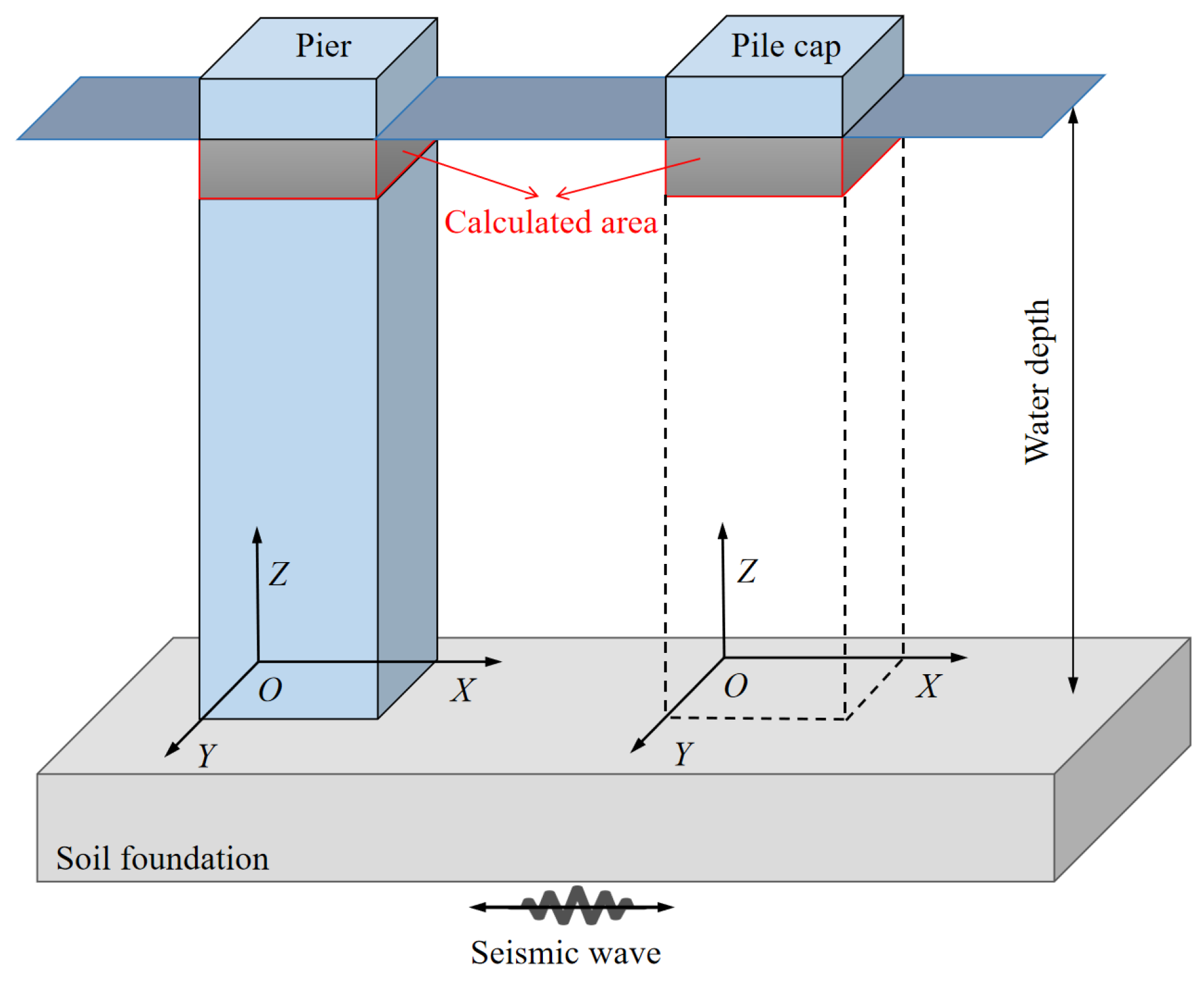
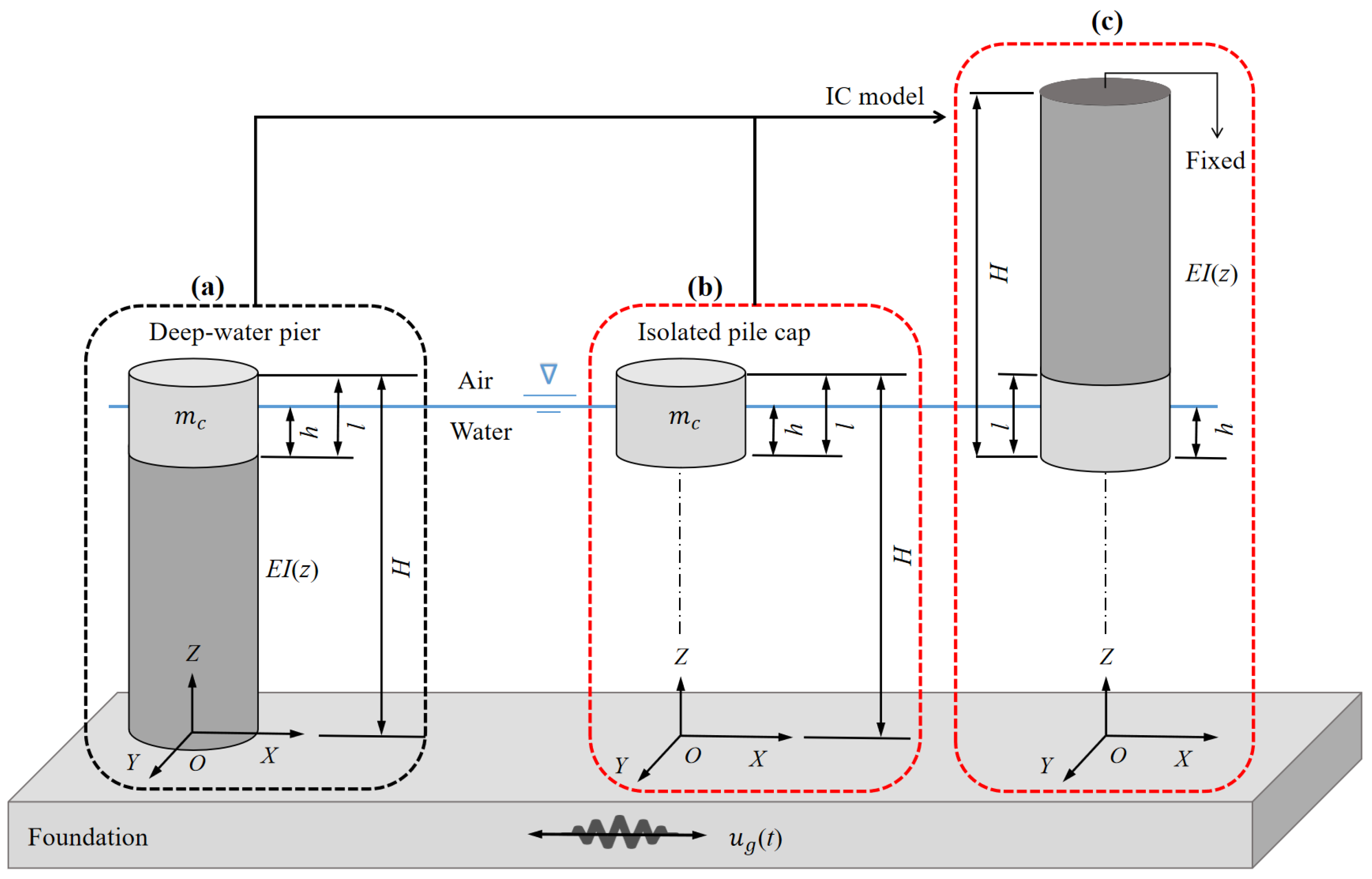
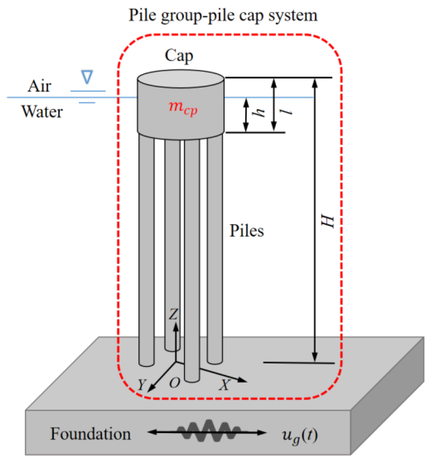
2. Comparison of Hydrodynamic Forces on Pier, Isolated Pile Cap and Pile Cap in Pile Group-Pile Cap System

At present, many seismic design codes only provide calculation methods for hydrodynamic forces on deep-water piers with arbitrary cross-sections. Therefore, the hydrodynamic force calculation methods for piers are typically adopted as equivalent methods to estimate the hydrodynamic forces on isolated pile caps in real practice, which inevitably ignores the influence of the flow-around effect at the cap bottom on hydrodynamic force [12]. Meanwhile, the pile cap is generally supported by pile groups, and how the flow-around effects at the cap bottom influence hydrodynamic forces on pile caps when comparing the isolated pile caps with pile group-pile cap systems are obviously different. In this section, the hydrodynamic forces on the isolated pile cap structure ( F I C t ) and on the pile cap in the pile group-pile cap system ( F P C t ), as well as on the pier ( F P t ) with the same submerged segment as the pile cap, will be comprehensively compared. According to the study by Zhang et al. [16], the influence of water free surface on structure hydrodynamic force is very limited. Therefore, the free surface wave effects are ignored intentionally in the numerical calculations in this study, which will be further studied in the future.

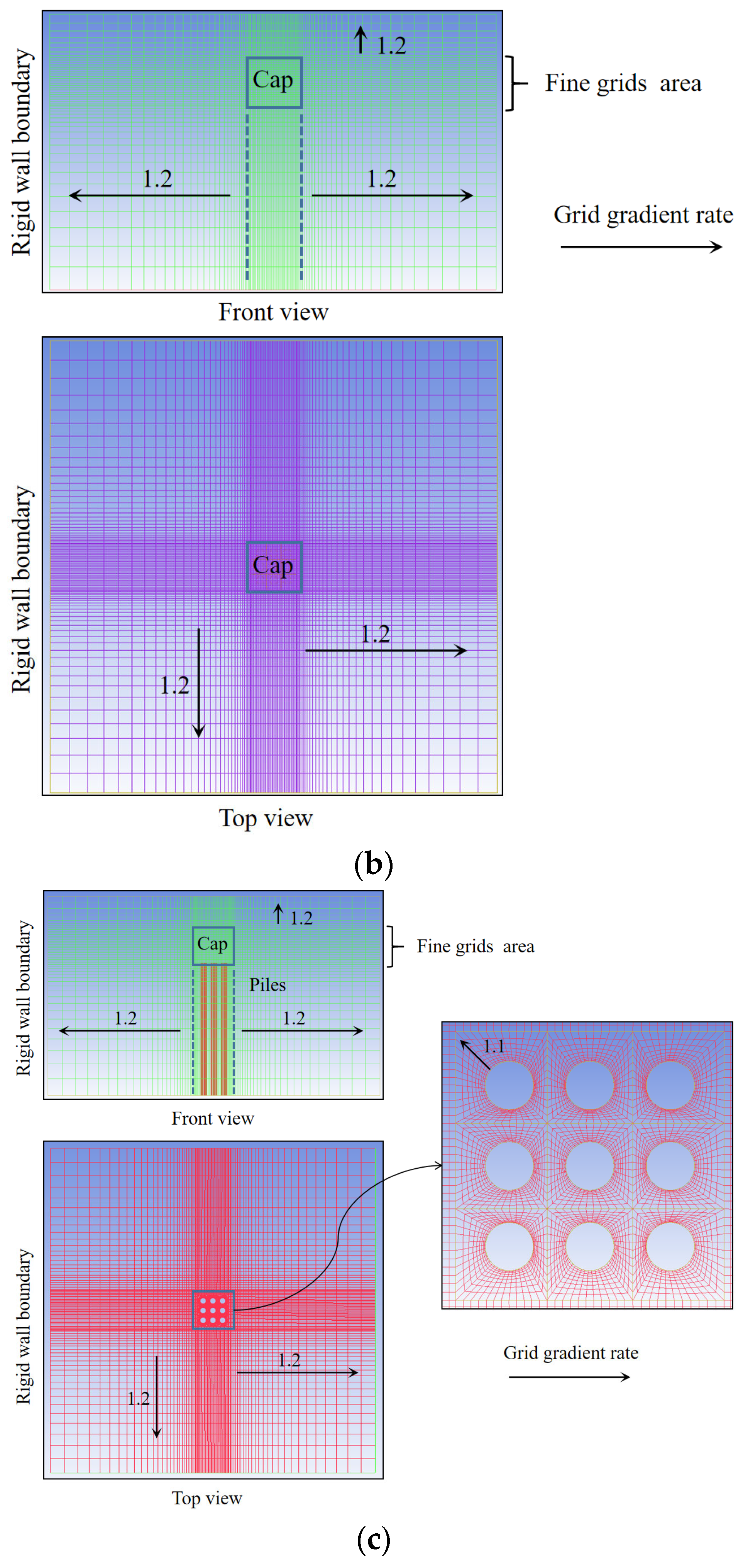
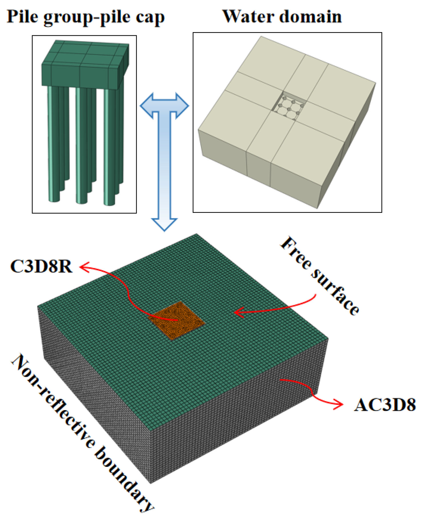
2.1. Numerical Simulation

2.1.1. Basic Information

The sectional dimensions of the rectangular pier, the isolated rectangular pile cap, and the pile group-pile cap system are shown in Figure 3. The length ( l p ), width ( w p ) and height of the rectangular pier are 5.0 m, 5.0 m, and 25.0 m, respectively (Figure 3a). In Figure 3b,c, the sectional dimensions of the pile cap are consistent with those of the pier, and the cap height is 5.0 m with a submerged depth h (unit: m). In Figure 3c, there are 9 piles below the pile cap, and the diameter and height of the piles are 0.9 m and 20.0 m, respectively. The length and width of the numerical calculation domain are set as L (unit: m) and W (unit: m), respectively. According to the study by Zhang et al. [18], the influence of blocking ratio on the hydrodynamic force can be ignored when L / l p > 6 and W / w p > 6 . Therefore, L and W are both set to 50.0 m, and the height of the numerical calculation domain is 30.0 m. The water depth is H w (unit: m). A study by Yang et al. [2] proved that the influence of hydrodynamic force on dynamic response of piers or pile group-pile cap structures under seismic excitation is equivalent to the sum of influences under a series of sinusoidal excitations with different frequencies and amplitudes. Therefore, the sinusoidal excitations with the function X t = A s i n 2 π f t are adopted to excite the pier, the isolated pile cap, and the pile group-pile cap system horizontally [2], where A (unit: m) is the excitation amplitude and f (unit: Hz) is the excitation frequency.
The ANSYS (2020) (FLUENT) software is adopted to simulate the structures vibrating horizontally in water, and the numerical grids generated by ANSYS (ICEM) for calculations are shown in Figure 4. Except for the pile groups below the cap in Figure 4c, the mesh generation methods for the three types of structures in Figure 4 remain consistent in modeling. To accurately monitor and compare the flow field characteristics and hydrodynamic forces on pile caps in the three types of structures, the fine grids are generated in the three types of structures in the direction of the pile cap vibration. The detailed modeling information is shown in Table 1. The numerical grids must be continuously regenerated to satisfy the solutions of the fundamental fluid equations (namely, the Navier–Stokes equations) during the structure vibration [2]. Therefore, the dynamic mesh technology is employed in all cases. The structures vibrating in water during an earthquake are characterized by a high Reynolds number and significant boundary layer effects. Therefore, in this study, the k ε   R N G turbulence model, is selected specifically to adapt for high Reynolds number conditions. Moreover, the wall function method is employed to properly consider the boundary layer effects [2,18]. According to the study by Yang et al. [5], gravity is the only restoring force for the free surface wave, the relationship between the gravitational acceleration g and the excitation frequency f   i s   g   / ( 2 π f ) = 0 when the free surface wave is ignored. Therefore, the gravitational acceleration g is set to 0 to eliminate the influence of free surface waves on the hydrodynamic force in all cases.

2.1.2. Numerical Model Validation

  • Validation of rectangular pier and isolated rectangular pile cap
In this subsection, the water depth H w is set to 25.0 m. Since the grid generation methods of the pier and pile cap are the same, and the study objects are close to the water’s free surface, the hydrodynamic forces on unit heights on the pier with submerged depth smaller than 5.0 m (i.e., the pier height is in the scope of 20.0–25.0 m) are verified. Yang and Li put forward a modified method to calculate the added masses on circular and rectangular piers caused by outer water without considering the free surface wave [5]. The expression for the added mass per unit height M z r e c of the rectangular pier is:
M z r e c = M w a t o · M z S R O · p s q u · p r e c
M w a t o = ρ w π a 2 / 4
M z S R O = 1 5 a H w 2 1 e x p 10 z H w a H w 1 / 3
p s q u = 1.4 . + a H w 100 10 4
p r e c = 1 + 15 a a H w + 6.5 H w 100 20 a 2 + 50 H w 800 ln l a b   l a b < 1   1 + ln H w ln l a b 0.5 a + 0.028 H w + 28       l a b > 1
where a is the width of the upstream surface on pier; M z S R O is the added mass coefficient of the circular pier; p s q u and p r e c are the shape coefficients of the square pier and the rectangular pier, respectively; l a b is the length-width ratio of the rectangular pier. For other variables, please refer to the study by Yang and Li [5]. Now three excitations with different frequencies (i.e., f = 0.50 Hz, f = 2.00 Hz, and f = 4.00 Hz) but the same amplitude ( A = 0.30 m) are selected to excite the pier horizontally. The numerical simulation results and the results calculated by Equation (1) are compared in Figure 5. It can be seen that the numerical simulation results ( M z N u m r e c ) approximate the results calculated by Equation (1) ( M z T h e r e c ) under the different cases (the relative errors μ in Figure 5 is μ = ( M z n u m r e c M z t h e r e c ) × 100 % / M z t h e r e c ).
2.
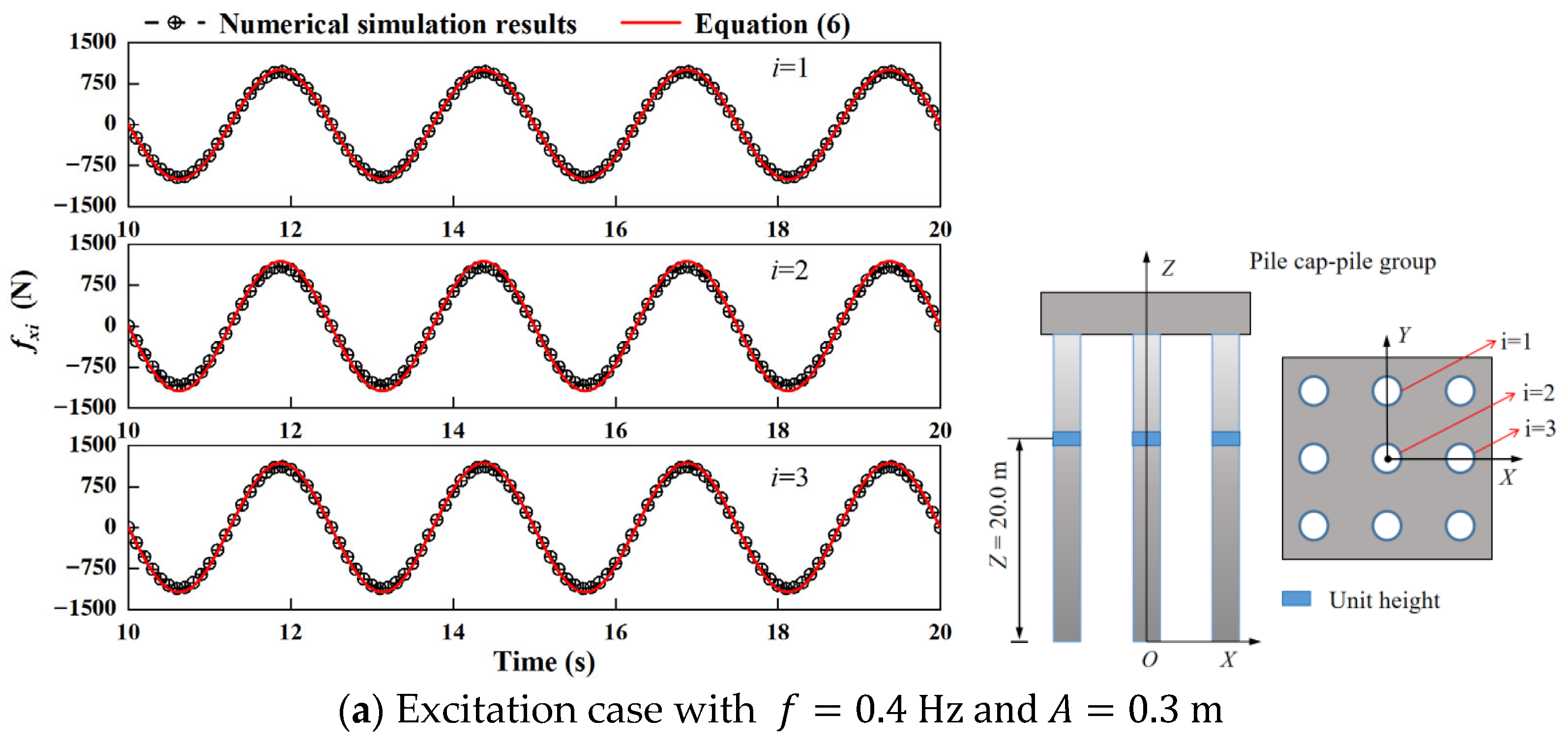
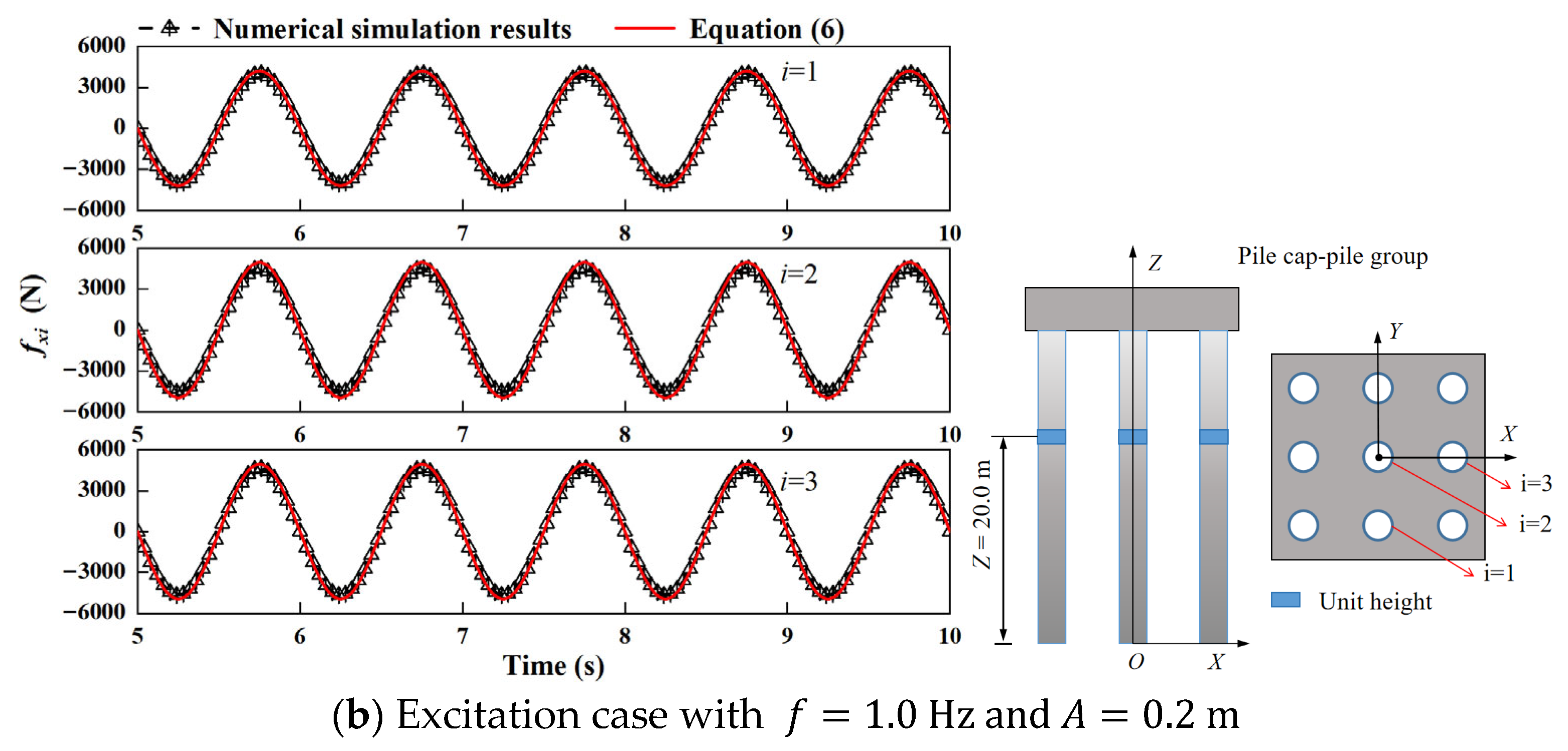
Validation of pile groups
The unit height hydrodynamic force of any single pile in pile groups is assumed to remain unchanged. Yang et al. [7] derived analytical expressions for the hydrodynamic forces on pile groups without considering the free surface wave based on the potential flow theory and verified it by numerical simulations. The expression of hydrodynamic forces on per unit height on pile groups is:
f x i = m X ¨ t 1 + j = 1 n h x i j f y i = m X ¨ t j = 1 n h y i j   j i ,
m = ρ w π r 2
h x i j = 2 cos 2 θ 0 i j c i j 2 h y i j = 2 sin 2 θ 0 i j c i j 2     θ 0 i j ϵ 0 ,   2 π
c i j = L i j r
where f x i , f y i denote the hydrodynamic forces acting on the i-th pile in directions parallel and perpendicular to the vibration direction of the pile groups, respectively; m is the mass per unit height of the pile; n is the total number of piles; r is the radius of a single pile; h x i j   a n d   h y i j   d e n o t e   t h e   a d d e d   m a s s   c o e f f i c i e n t s ;   L i j is the center-to-center distance between any two piles (i-th and j-th) in the pile groups; and θ 0 i j is the angle between the center line connecting any two piles (i-th and j-th) and the direction of seismic waves. For the detail derivation and explanation of terms in Equations (6)–(9), please refer to the study by Yang et al. [7]. When H w = 25 m, the excitations X ( t ) = 0.3 s i n ( 2 π × 0.4 t ) and X ( t ) = 0.2 s i n ( 2 π × 1.0 t ) are selected to excite the pile group-pile cap structure horizontally. The comparison of unit hydrodynamic forces on piles at Z = 20 m between the numerical simulation results and the results calculated by Equation (6) are shown in Figure 6. It can be seen that the change trends of time history curves of hydrodynamic forces between the theoretical calculation results and the numerical simulation results on 3 piles under different cases are well consistent with each other.
In conclusion, the numerical models established in this study can be adopted for the analysis of the hydrodynamic forces on the rectangular pier, the isolated rectangular pile cap, and the pile group-pile cap system.

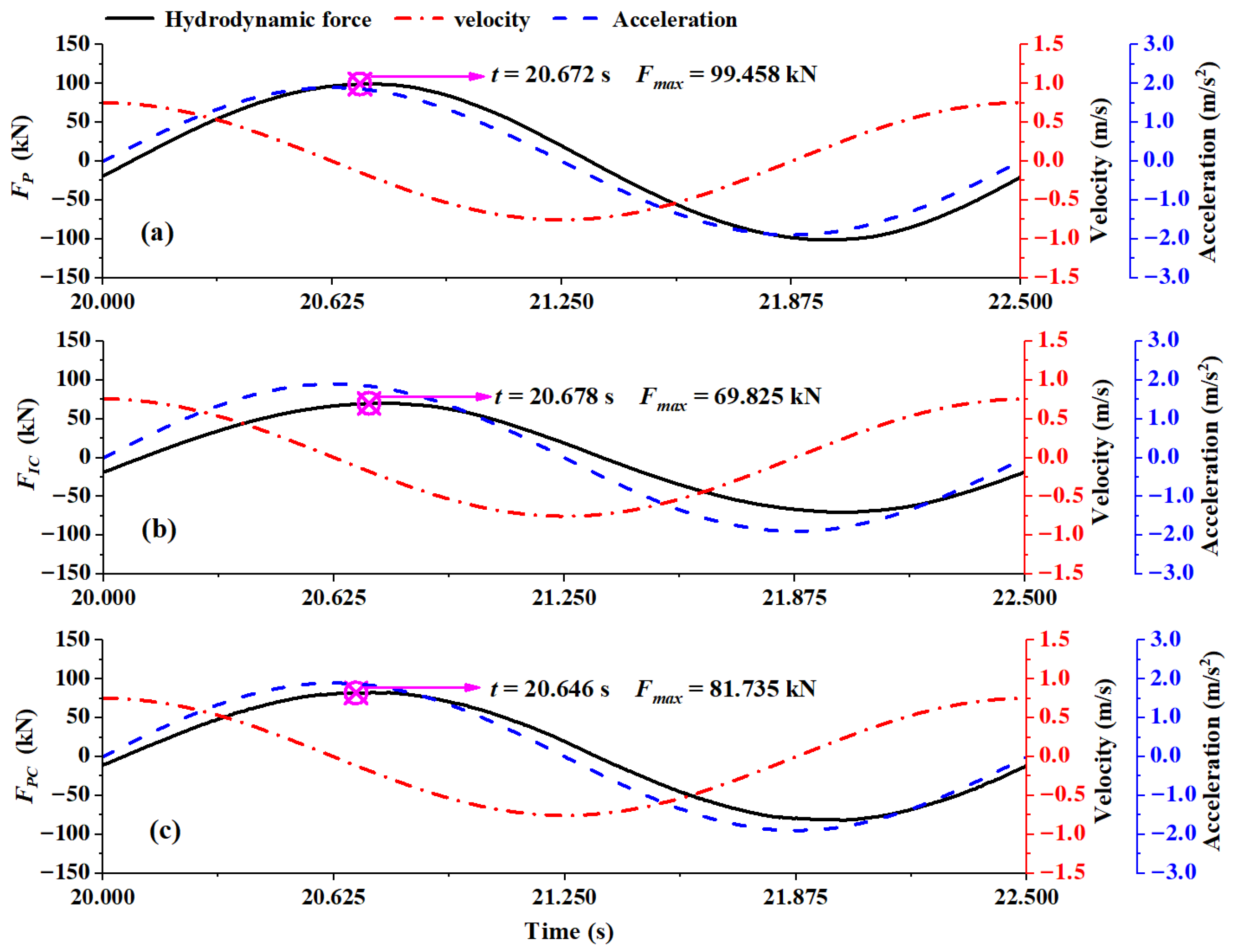
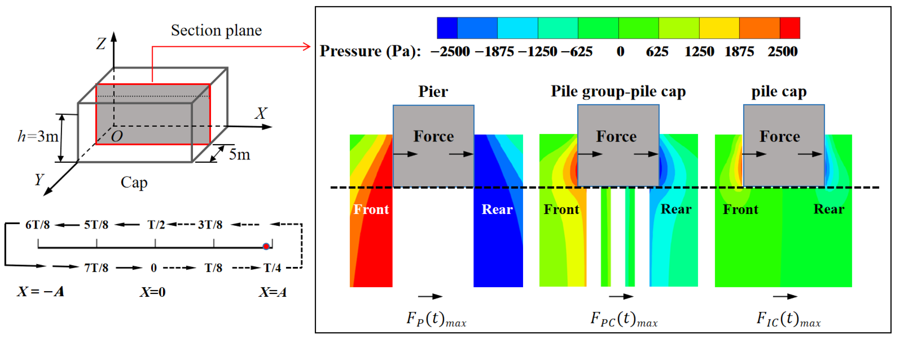
2.2. Comparison of Hydrodynamic Forces Between F P t , F I C t and F P C t

When H w = 23 m and the excitation is X t = 0.3 sin 2 π × 0.4 t , the time history curves of F P t , F I C t and F P C t are shown in Figure 7. Since the sectional dimensions of the study objects are large enough and the structures vibrating in water during earthquakes are characterized by high Reynolds numbers, the viscous effect of the structures vibrating in water can be ignored [15,18], and the influence of the free surface wave on the hydrodynamic forces is not considered intentionally in this study. Therefore, according to the study by Zhang et al. [12] and Yang et al. [5]. F P t , F I C t and F P C t are all mainly composed of the inertial force, which is the product of the mass and acceleration of water with the same volume as that displaced by the vibration structures, namely:
F P t = C m P ρ w l p w p h X ¨ t
F I C t = C m I C ρ w l p w p h X ¨ t
F P C t = C m P C ρ w l p w p h X ¨ t
where C m P C m I C and C m P C denote the added mass coefficients of the hydrodynamic forces. C m P , C m I C   a n d   C m P C are only dependent on the geometric characteristics but not influenced by the excitation cases [5,12], which can be calculated by Equation (10), Equation (11) and Equation (12) respectively. In other words, the hydrodynamic force is directly proportional to the excitation acceleration.
Therefore, in Figure 7, the change trends of F P t F I C t and F P C t remain almost consistent, and the occurrence time of F P t m a x , F I C t m a x and F P C t m a x extremely approaches that of X ¨ t . However, the difference in the values of F P t m a x , F I C t m a x and F P C t m a x is highly significant. It can be observed that F P t m a x is 42.44% larger than F I C t m a x , indicating that the existing method of employing calculation methods developed for deep-water piers to estimate hydrodynamic forces on isolated pile caps with the same cross-sections in real practice is very inaccurate and inapplicable. Similarly, it can be seen that F P C t m a x is 17.05% larger than F I C t m a x , indicating that the hydrodynamic forces on pile caps in pile group-pile cap systems are amplified by ignoring the influence of group piles, which will result in non-negligible errors in real practice.
According to Equations (10)–(13) and Figure 7, the hydrodynamic forces acting on the structures are primarily positively correlated with the acceleration X ¨ t , while there is almost no dependence on the velocity X ˙ t of the structural vibration. This reveals that the earthquake-induced hydrodynamic force is primarily provided by the static pressure p s t a from the surrounding water, while the contribution from the dynamic pressure p d y n by the water around the structure accounts for a very small proportion and can be ignored [19] ( p s t a is positively correlated with the acceleration of water quality points; p d y n is positively correlated with the water velocity [19]). Correspondingly, When F P t m a x , F I C t m a x and F P C t m a x arrive at their maximums, the static pressure in the XOZ plane of the rectangular pier, the isolated rectangular pile cap, and the pile group-pile cap are compared in Figure 8, respectively.
In Figure 8, the pressure gradient force always acts from high-pressure to low-pressure regions in the flow field generated by the submerged structure vibration. At the front of the vibrating structures, the water is driven by the structure and moves in the same direction as the structures. Consequently, the high-pressure regions are formed in the flow field near the front of the structures, while the infinite flow field is regarded as the low-pressure regions. Therefore, the structures are subjected to the hydrodynamic force opposing the structure motions at the upstream surface of the structures. Similarly, at the rear of the vibrating structures, the water is required to follow the structure motions. At this time, the low-pressure regions are generated in the flow field near the rear of the structures. Therefore, the structures are also subjected to the hydrodynamic force opposing the structure motions at the downstream surface of the structures. However, since the flow-around effect at the bottom of the isolated pile cap is significantly stronger than that of the pile group-pile cap and pier, the pressure gradient force (as shown in Figure 8) acting on the upstream and downstream surfaces of the isolated pile cap is significantly smaller than that of the pile group-pile cap system and pier under the same cases. Therefore, F P t m a x > F P C t m a x > F I C t m a x .
Generally, the boundary conditions of the interaction between water and either isolated pile caps or pile group-pile cap systems are recognized to be extremely complex [20], thus resulting in a very significant difference between F P t m a x , F I C t m a x and F P C t m a x under the same cases. Analytical deriving hydrodynamic forces on isolated pile caps under seismic action based on the radiation wave theory are full of challenges. Furthermore, such analytical solutions are typically limited to isolated pile caps with simple cross-sections (e.g., circular pile caps), severely restricting their practical applicability [13]. Numerical modeling methods employing computational fluid dynamics (CFD) software (e.g., ANASYS-FLUENT) have been demonstrated to accurately calculate the hydrodynamic forces on the isolated pile cap or on the pile cap in the pile group-pile cap system. However, the modeling process is complicated, and the calculation time is unacceptable in real practice [21] (Table 1 in Section 2.1).

3. Establishment of Dynamic Equilibrium Equations

In fact, the hydrodynamic forces acting on the deep-water structure under earthquakes can be fundamentally considered as the added mass [3,4,18]. Therefore, in this study, the simple and engineering-acceptable hydrodynamic force calculation methods for the isolated pile cap or for the pile cap in the pile group-pile cap system are derived by the structural dynamics theory, which can avoid the complicated structure–water interaction problem.

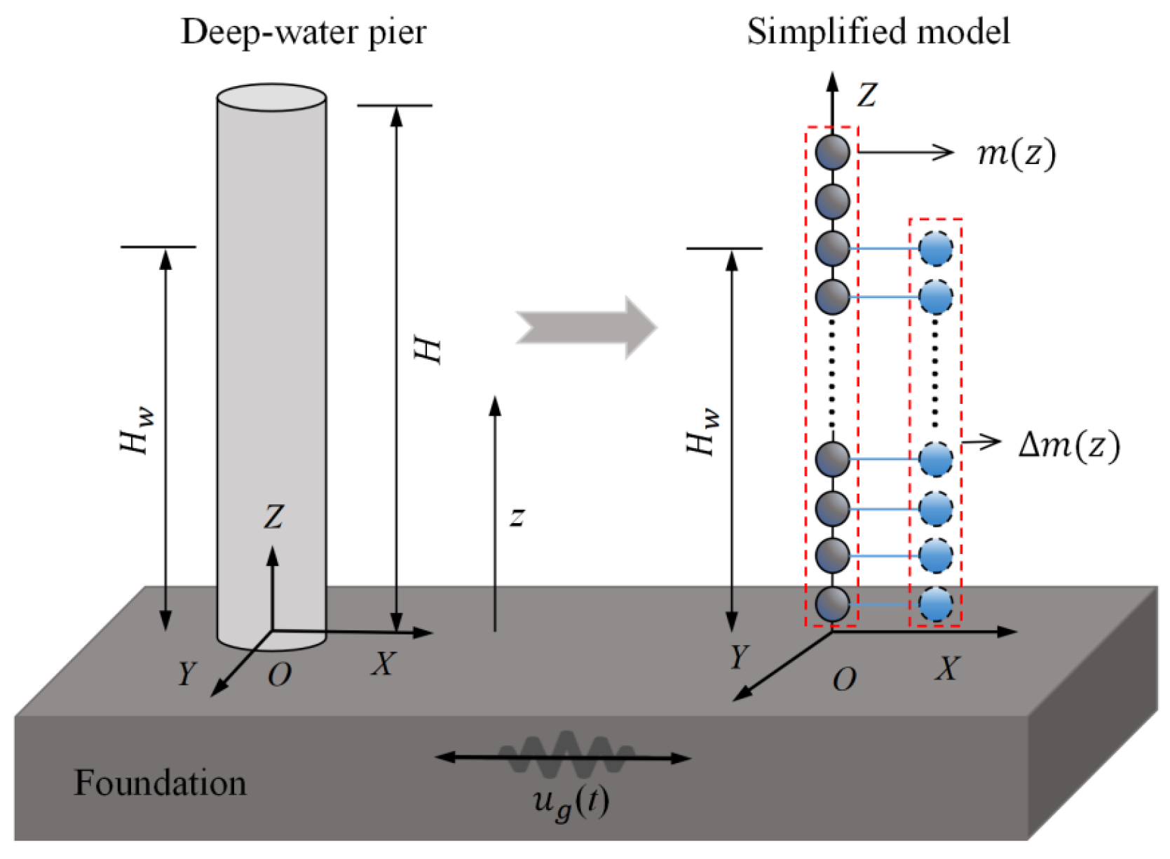
3.1. Motion Equation for Deep-Water Pier Under Earthquake

The simplified analysis model of the deep-water pier under horizontal earthquakes is shown in Figure 9. The height and the submerged water depth of the pier are defined as H and H w ( 0 H w H ), respectively. The pier is considered to be elastic, and the bending stiffness of the pier on per unit height is E I z . The mass on the pier itself is uniformly distributed in the Z-axis, and mass on per unit height is set to m z . Δ m z is the added mass on pier unit heights generated by the pier–water interaction. u g t is the ground vibration displacement. Given that the pier has a considerable height and relatively high flexibility, its vibration is primarily dominated by lateral bending and remains within the elastic range. Since the influence of the water damping on the seismic response of the pier is extremely small, and correspondingly can be ignored [3,4], the motion of the pier during earthquakes can be regarded as undamped forced vibration.
Assuming that the ground motion displacement is u g t , and the displacement of the deep-water pier relative to the ground is u z , t , then the total displacement u t z , t of the pier is:
u t z , t = u g t + u z , t ,
The pier vibration u z , t can be expressed using the shape function ς z and the single generalized displacement q t coordinate, as follows:
u z , t = ς z q t ,
According to Zhang et al. [4], the expression for the shape function of the deep-water pier can be expressed as:
ς z = 3 H z 2 z 3 / 2 H 3 ,
Now the inertial force term during the pier vibration is denoted as F z , t . Based on the D’Alembert principle [4], the inertial force can be expressed as:
F z , t = m z u ¨ t z , t = m z u ¨ z , t + u ¨ g t ,
Based on Equation (7), the virtual work δ W 1 done by the inertial force under virtual displacement δ u z can be derived as:
δ W 1 = 0 H m z u ¨ z , t δ u z d z 0 H m z u ¨ g t δ u z d z ,
Meanwhile, during the vibration of the pier, the virtual work δ W 2 performed by the bending moment M z , t at the pier base on the curvature δ κ z corresponding to the virtual displacement can be expressed as:
δ W 2 = 0 H M z , t δ κ z d z = 0 H E I z u z , t δ 2 u z 2 d z ,
According to the principle of virtual work, the virtual work done by the inertial force δ W 1 should be equal to the internal virtual work δ W 2 done by the bending moment at the pier base. By combining Equations (8) and (9), the dynamic equilibrium equation for the deep-water pier under seismic action can be expressed as:
M q ¨ t + K q t = P u ¨ g t ,
where M , K , and P represent the generalized mass, generalized stiffness, and generalized excitation, respectively, namely:
M = 0 H w m z + Δ m z ς z 2 d z + H w H m z ς z 2 d z ,
K = 0 H E I z ς z 2 d z
P = 0 H w m z + Δ m z ς z d z + H w H m z ς z d z

3.2. Motion Equation for Isolated Pile Cap Without Considering Pile Groups

Figure 10a,b, respectively, shows a deep-water pier and an isolated pile cap. The pier has a fixed base connection, and the pier height is H . The isolated pile cap is a floating, truncated structure with a submerged depth of h , a total height of l , and a distance of H between the cap top and its foundation. The cross-sectional dimensions and shape of the cap are consistent with those of the pier. Since the cap typically remains partially submerged in real practice under the design normal water level, and complete submergence of the cap is avoided to ensure navigation safety even during the high-water level conditions [17], it could be assumed that the cap will not be fully submerged during its service life. Therefore, based on Figure 10a, the pier position can be relocated to Figure 10c with the pier top fixed. Then the hydrodynamic force on the pier in Figure 10c (which has the same submergence depth as the cap in Figure 10b) can be equivalently used to calculate the hydrodynamic force on the isolated pile cap in Figure 10b, and then the influence of the bottom flow around the cap on the hydrodynamic force can be eliminated.
According to Figure 10c, a simplified analytical model (namely, the IC model) for the isolated pile cap under seismic excitation can be established as shown in Figure 11.
Since the cap height is relatively smaller than the pier height in real practice, the cap is typically considered as a concentrated mass in the dynamic response analysis of bridges during earthquakes [4,12,16]. Consequently, both the structural mass of the cap m c and its hydrodynamic added mass m c are considered in the form of concentrated masses, and m c represents the total added mass corresponding to the submerged segment of the cap. Meanwhile, the IC model in Figure 11 requires the following fundamental assumptions: (1) The vibration form is predominantly governed by lateral bending, with torsional and rotational effects of the pile cap being neglected; (2) the IC model is fixed at the top and remains free at the base; and (3) the damping effect of water and the influence of water on the bending stiffness of the structure are excluded from consideration. Therefore, the motion of the IC model under earthquakes is the undamped forced vibration. φ z is defined as the shape function for the IC model. Note that the fundamental distinction between the models in Figure 9 and Figure 11 lies in their respective mass distributions in the Z-axis. However, since both models share identical boundary conditions (for the pier model in Figure 9, the boundary condition can be expressed as ς 0 = ς ˙ ( 0 ) = 0 ; For the IC model in Figure 11,the boundary condition can be expressed as φ 0 = φ ˙ ( 0 ) = 0 ), they can adopt the same formulation for their shape functions. Furthermore, gravitational effects in the IC model do not influence its horizontal dynamic equilibrium equations [4]. Therefore, the dynamic equilibrium equations for the IC model can be directly derived based on the theoretical framework established in Section 3.1.
The shape function formulation for the IC model is expressed as:
φ z = [ 3 ( H l ) z 2 z 3 ] / 2 ( H l ) 3 ,
The mass distribution in the Z-axis for the IC model is:
m I C z = m z 0 < z < H l m c + m c z = H l ,
According to the derivation of Equations (4)–(11), the equilibrium equation of the IC model shown in Figure 11 can be written as:
M I C q ¨ t + K I C t q t = P I C u ¨ g t ,
In Equation (25), M I C K I C , and P I C represent the generalized mass, generalized stiffness, and generalized excitation, respectively, that is:
M I C = 0 H l m z φ z 2 d z + m c + m c ,
K I C = 0 H l E I z φ z 2 d z
P I C = 0 H l m z φ z d z + m c + m c

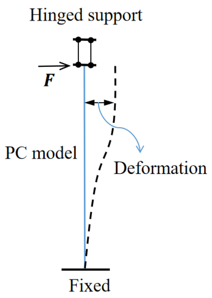
3.3. Motion Equation for Pile Group-Pile Cap System

After considering the interaction between pile groups and pile cap, the added mass on the pile cap will be increased slightly, while the added masses on the pile groups are almost constant [16]. Furthermore, when the overall height H t a l of the pile group-pile cap system is relatively higher (generally H t a l > 35.0 m), the flexibility of the entire system is relatively larger; thus, the entire system can be approximately considered as a single degree of freedom system. Therefore, the accurate added mass on the pile cap is of great significance for the analysis of the dynamic response of the system. In this section, the influence of the pile groups on the added mass on the pile cap is considered.
The pile group-pile cap system is shown in Figure 12, in which the cap height is l, and the distance between the cap top and the foundation is H. The mass and the hydrodynamic added mass per unit height of a single pile are defined as m p z and Δ m p z , respectively, and the bending stiffness of a single pile on per unit height is E p I p z . The cap mass and the hydrodynamic added mass on the cap are both concentrated mass (same as Section 3.2), which are, respectively, defined as m c p   a n d   m c p . Note that m c p is the total added mass on the cap in the submergence depth segment h . Now the number of pile roots is defined as n , then the simplified analysis model of the pile group-pile cap system (PC model) can be obtained according to Figure 12, as shown in Figure 13. The PC model needs to meet the following assumptions: (1) The vibration form is predominantly governed by lateral bending, with torsional and rotational effects of the cap being neglected; (2) The bottom of the PC model is fixed on the ground. (3) The damping effect of water and the influence of water on the bending stiffness are not considered. Based on the above, the motion of the PC model under earthquake can also be considered as the undamped forced vibration.
Although the simplified analytical models in Figure 9 and Figure 13 exhibit considerable similarity, however, the pile group-pile cap system is a composite structure, and the bending moment will inevitably develop at the connection between the cap and pile group during vibration. This mechanical behavior fundamentally differs from the boundary conditions of the model in Figure 9. Consequently, the shape function σ z for the PC model in Figure 13 exhibits distinct characteristics from ς z . The boundary constraints and deformation of the PC model are shown in Figure 14 (the boundary condition for the PC model can be expressed as σ 0 = σ ˙ ( 0 ) = 0 ,   σ ˙ H l = 0 ). One method for determining the shape function involves defining the deformation caused by some specific static forces as the shape function; for the detailed derivation, please refer to reference [4]. Here, let the force F in Figure 14 be the unit force, and the shape function can be derived by the structural mechanics theory, with its expression given by:
σ z = [ 3 ( H l ) z 2 2 z 3 ] / ( H l ) 3 ,
Although the simplified analytical models in Figure 9 and Figure 13 differ in shape functions and structural composition, the methodology for deriving their dynamic equilibrium equations remains consistent. And the dynamic equilibrium equations for the PC model can be derived based on Equations (4)–(11).
The mass distribution in the Z-axis for the PC model is:
m P C z = n m p z + Δ m p z 0 < z < H l m c p + m c p     z = H l ,
According to the derivation of Equations (4)–(11), the equilibrium equation of the PC model shown in Figure 13 can be written as:
M P C q ¨ t + K P C t q t = P P C u ¨ g t ,
In Equation (31), M P C , K P C , and P P C represent the generalized mass, generalized stiffness, and generalized excitation, respectively, namely:
M P C = 0 H l n m p z + Δ m p z σ z 2 d z + m c p + m c p ,
K P C = 0 H l n E p I p z σ z 2 d z
P P C = 0 H l n m p z + Δ m p z σ z d z + m c p + m c p

4. Calculation Method for Added Mass on Pile Caps with Arbitrary Cross-Sections

4.1. Derivation of m c and m c p

Added mass on the isolated pile cap without considering pile groups
Now the fundamental frequency of the IC model is defined as ω I C . According to Equations (26)–(28), the expression of ω I C is as follows:
ω I C = 0 H l E I z φ z 2 d z 0 H l m z φ z 2 d z + m c + m c ,
ω I C 2 = 0 H l E I z φ z 2 d z 0 H l m z φ z 2 d z + m c + m c
0 H l E I z φ z 2 d z / ω I C 2 = 0 H l m z φ z 2 d z + m c + m c
According to Equation (37), the expression of the added mass m c on the isolated cap is:
m c = 0 H l E I z φ z 2 d z / ω I C 2 0 H l m z φ z 2 d z m c ,
In Equation (38), parameters such as H , l , E I z ,   m z , φ z and m c can all be calculated directly in real practice. Therefore, the result of m c depends solely on the fundamental frequency ω I C .
Added mass on the pile cap in the pile group-pile cap system
Similarly, the fundamental frequency of the PC model is defined as ω P C . According to Equations (32)–(34), the expression of ω P C is:
ω P C = 0 H l n E p I p z σ z 2 d z   0 H l n m p z + Δ m p z σ z 2 d z + m c p + m c p ,
ω P C 2 = 0 H l n E p I p z σ z 2 d z   0 H l n m p z + Δ m p z σ z 2 d z + m c p + m c p
0 H l E p I P z σ z 2 d z / ω P C 2 = 0 H l n m p z + Δ m p z σ z 2 d z + m c p + m c p
According to Equation (41), the expression of the added mass m c p on the pile cap in pile group-pile cap structure is:
m c p = 0 H l E p I p z σ z 2 d z / ω P C 2 0 H l n m p z + Δ m p z σ z 2 d z m c p ,
In Equation (42), parameters such as H , l , E p I p z ,   m p z , σ z and m c p can all be directly calculated in real practice. Therefore, the result of m c p depends on the added mass for pile groups Δ m p z and the determination of fundamental frequency ω P C . The calculation method for the added mass on pile groups Δ m p z can be referred from Yang et al. [7]. Consequently, ω P C remains the only unknown variable in Equation (42).

4.2. Acoustic-Solid Coupling Theory
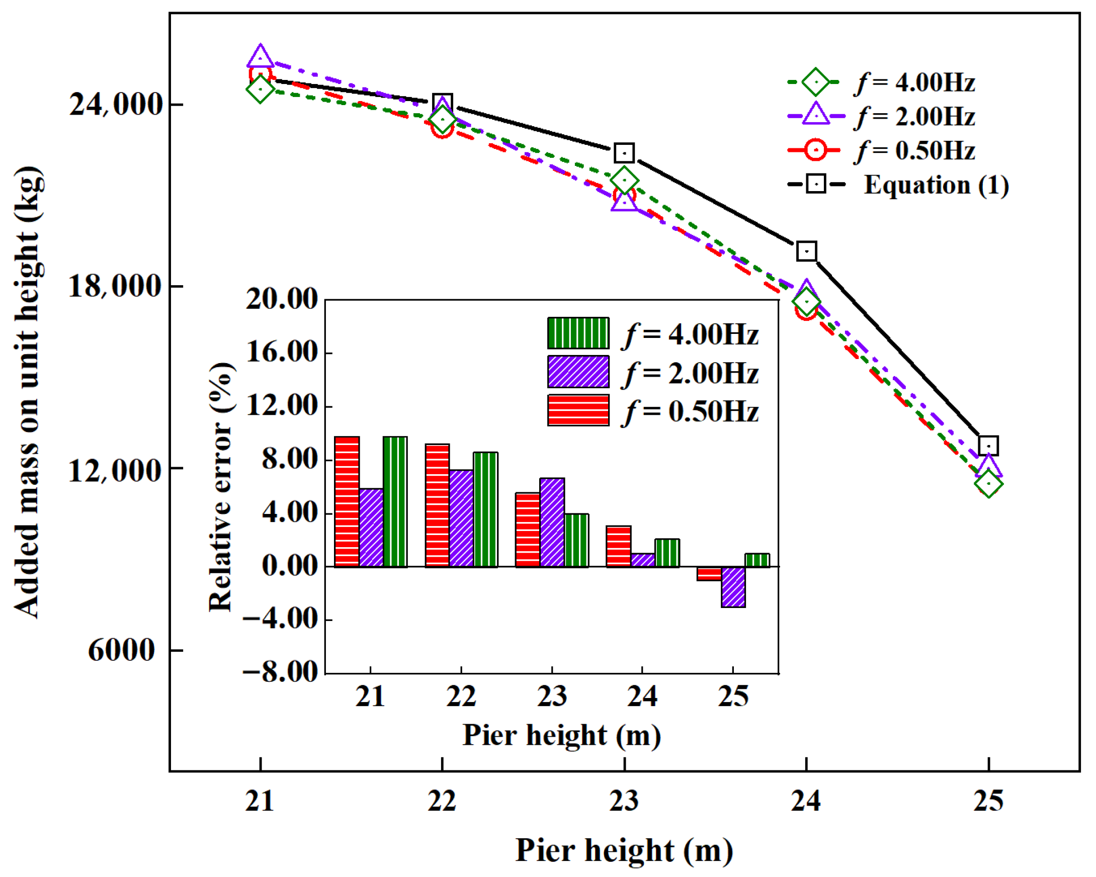
The acoustic-solid coupling theory in ABAQUS is a finite element method for solving the interaction between the compressible water and structures [22]. The water is regarded as an acoustic medium (i.e., an elastic medium that only exhibits pressure related to volumetric strain without shear stress) and is assumed to be the compressible ideal fluid. The constitutive equation of the acoustic medium can be expressed as:
p = K f ( x , θ i ) x u ˙ f ,
where p represents the water pressure; x represents the spatial coordinates of water particles; u ˙ f represents the velocity of water particles; θ i is the field variable independent of the water particle position; and K f is the bulk modulus of water.
Assuming that ε ν is the water volume strain, u f ,   u ¨ f are the displacement and acceleration of water particles, respectively. Then the expression of water pressure is:
p = K f ε ν = K f u x ,
According to Newton’s second law [22]:
p x = ρ f u ¨ f ,
Combining Equations (44) and (45) yields the wave equation with water pressure as the target variable:
p x ( p x ) = 1 c 2 p ¨ ,
where c is the velocity of sound in water, namely:
c = K f ρ f ,
The infinite water domain can be better simulated by the impedance boundary or non-reflecting boundary in an acoustic medium. That is, the flow field composed of acoustic media can satisfy the Sommerfield radiation condition at the infinity boundary of the water flow field [5]. In this study, the water is regarded as an acoustic medium; thus, the complex structures–water coupling problems are simplified into wet modal analysis problems of structures in water (i.e., calculations of ω I C and ω P C by finite element method). However, the acoustic-solid coupling method in ABAQUS is convenient to operate and widely applied in analyzing the frequencies of structures in water [22]. The structures in water are simulated by the three-dimensional solid element C3D8R. The water is simulated by the three-dimensional acoustic element AC3D8. The interface between the water (acoustic medium) and the structure is adopted with a “Tie” constraint to simulate their coupling interaction. The water surface is set as the free surface. A zero-impedance boundary condition is applied to the water domain boundaries to achieve the non-reflective boundary, thus simulating an infinite fluid domain.

4.3. Verification of m c and m c p

The detailed process of the calculation method for added masses on pile caps with arbitrary cross-sections based on the finite element method is shown in Figure 15. In this section, the method proposed in this study will be verified.

4.3.1. Engineering Case Application

The engineering case is referenced from the study by Zhang et al. [16], with the detailed information shown in Figure 16. The rectangular pile cap has both a length and a width of 12.0 m, with a height of 3.5 m. Nine piles are arranged below the cap, each with a length of 20.0 m and a diameter of 1.8 m. The elastic modulus, Poisson’s ratio, and density of the pile group-pile cap system are 32.5 GPa, 0.2, and 2500 kg/m3, respectively. The total submerged depth of the pile group-pile cap system is 23.0 m. The bottom of the pile group-pile cap system is fixed, while the top is free.
Based on the above information, Figure 17 and Figure 18 present the IC and PC finite element models, where the influence of the pile groups is ignored and considered, respectively. The water domain has dimensions of 100 m × 100 m, with a wave velocity of the sound wave in the water of 1460 m/s and a water density of 1000 kg/m3.
The fundamental frequencies of the IC model and the PC model obtained by ABAQUS in Figure 16 and Figure 17 are substituted into Equations (21) and (23). The calculation results of m c and m c p are 78.51 t and 94.4 t, respectively, and note that the entire calculation process does not exceed 20 min. Meanwhile, m c and m c p are 75.7 t and 85.4 t, respectively, in the study by Zhang et al. [16]. It can be seen that the accuracy and efficiency of the calculation method in this study are acceptable in real practice.

4.3.2. Comparison of Different Added Mass Calculation Methods for Pile Caps

In this section, the added mass calculation methods proposed in this study (namely, Equations (21) and (23)) for pile caps are compared with the Chinese code (Specifications for Seismic Design of Highway Bridges) and the simulation results in Section 2.2. (Note that the numerical simulation results have been proven to have high accuracy in Section 2.1.2). The pile group-pile cap foundation is shown in Figure 3, and the modeling techniques in ABAQUS are the same as those in Section 4.3.1. The detailed comparison results of different added mass calculation methods for pile caps are shown in Table 2. For convenience, the results of added masses for pile caps calculated by Equations (21) and (23), Chinese code, and simulations in Section 2.2 are defined as M T H E , M C O D , and M N U M , respectively. The relative error τ in Table 2 is expressed as τ = M M N U M × 100 % M N U M ,   M is equivalent to M T H E or M C O D . It can be seen that the values of M T H E approximate to that of M N U M regardless of the structure type, indicating that the calculation method proposed in this study has high accuracy. However, the value of M C O D is much larger than that of M N U M regardless of the structure type, indicating that the hydrodynamic force calculation method in the Chinese code for the pile cap will overestimate the hydrodynamic force on the pile cap in real practice.

5. Discussion

Although the efficient and applicable hydrodynamic force calculation method for the pile cap with arbitrary cross-sections is presented in this study, it should be noted that there are still several limitations for improvement: Firstly, the influence of structure damping is not considered during the derivation of the dynamic equilibrium equations in Section 3. However, the existence of the structure damping can affect the fundamental frequency of the structure, which may in turn affect the accuracy when calculating the hydrodynamic force on the pile cap by using Equations (21) and (23). In the subsequent studies, the influence degree of structure damping on the hydrodynamic force on the pile cap deserves thorough discussion. Moreover, it would be worthwhile to introduce a damping influence coefficient to quantitatively demonstrate the structure damping effect based on the calculation method proposed in this study. Secondly, the verification samples for the calculation method in this study are limited. To further verify its accuracy, additional experimental studies and numerical simulations should be conducted, particularly focusing on pile caps with arbitrary cross-sectional shapes. Finally, the hydrodynamic force calculation method for pile caps proposed in this study, as expressed in Equations (21) and (23), involves relatively complex formulations. To improve calculation efficiency and practical applicability, further studies could simplify these expressions through extensive experimental and numerical investigations.

6. Conclusions

Pile group-pile cap structures are widely employed in the construction of deep-water bridges. In this study, a simplified and practically acceptable method for calculating the hydrodynamic forces on pile caps is proposed based on structural dynamics theory and finite element software modeling. The main conclusions are summarized as follows:
(1)
The existing methods for employing pier calculation methods to estimate hydrodynamic forces on isolated pile caps with the same cross-sections are inaccurate and inapplicable.
(2)
The influence of pile groups on the hydrodynamic force on pile caps should be considered in real practice.
(3)
The dynamic equilibrium equation of the IC model under seismic action is derived, and the hydrodynamic force calculation method for the isolated pile cap with arbitrary cross-sections is established.
(4)
The dynamic equilibrium equation of the PC model under seismic action is derived, and the hydrodynamic force calculation method for the pile cap in the pile group-pile cap system is proposed.
(5)
The effectiveness of the hydrodynamic calculation methods proposed in this study is verified, and the proposed method is proven to have a wide application and higher computational efficiency.

Author Contributions

Conceptualization, W.Y.; data curation, Y.X.; formal analysis, W.Z.; funding acquisition, W.Y.; investigation, S.X.; methodology, S.X.; software, X.G.; supervision, Y.X.; validation, W.Z., X.G. and S.X.; writing—original draft, W.Z.; writing—review and editing, Y.X. All authors have read and agreed to the published version of the manuscript.

Funding

This research was funded by Science and Technology Project of China Road and Bridge Corporation with Grant No. P2220447, and by Science and Technology Planning Project of Sichuan Province with Grant No. 2023YFS0429, and also supported by National Natural Science Foundation of China with Grant No. 52468028. The numerical calculations in this paper have been done on Hefei advanced computing center.

Data Availability Statement

Research data are available in the body of the article.

Acknowledgments

The authors are grateful for financial support from the Science and Technology Project of China Road and Bridge Corporation with Grant No. P2220447, the Science and Technology Planning Project of Sichuan Province with Grant No. 2023YFS0429, and the National Natural Science Foundation of China with Grant No. 52468028.

Conflicts of Interest

Author Shizhou Xiao was employed by the company China Road & Bridge Corporation and Author Yifei Xu was employed by Sichuan Communication Surveying and Design Institute Co., Ltd. The remaining authors declare that the research was conducted in the absence of any commercial or financial relationships that could be construed as a potential conflict of interest.

Abbreviations

The following abbreviations are used in this manuscript:
u g t Ground vibration displacement
m c Isolated pile cap mass
m c Isolated pile cap hydrodynamic added mass
M I C Generalized mass for IC model
K I C Generalized stiffness for IC model
P I C Generalized excitation for IC model
φ ( z ) Shape function for IC model
m p z Mass per unit height of a single pile
Δ m p z Hydrodynamic added mass per unit height of a single pile
M P C Generalized mass for PC model
K P C Generalized stiffness for PC model
P P C Generalized excitation for PC model
σ ( z ) Shape function for PC model
m c p Hydrodynamic added mass on pile cap in pile group-pile cap system
ω I C Fundamental frequency of IC model
ω P C Fundamental frequency of PC model
H Total height of IC and PC model
H w Water depth
X ( t ) Earthquake excitation
A Excitation amplitude
f Excitation frequency
F I C ( t ) Hydrodynamic force on IC model
F P C ( t ) Hydrodynamic force on PC model
F P ( t ) Hydrodynamic force on bridge pier

References

  1. Chen, Y.; Yang, L.; Wu, K.; Huang, X. Centrifuge shaking table study on the hydrodynamic effects on a pile foundation bridge pier in soft soil under earthquakes. Mar. Struct. 2022, 85, 10326. [Google Scholar] [CrossRef]
  2. Yang, W.; Li, Q.; Yeh, H. Calculation method of hydrodynamic force on circular piers during earthquakes. J. Bridge Eng. 2017, 22, 04017093. [Google Scholar] [CrossRef]
  3. Zhang, W.; Ren, X.; Geng, X.; Zhang, Y.; Yang, W. Study on influence coefficients of hydrodynamic force on dynamic response of deep-water pier under earthquake. Ocean Eng. 2024, 299, 117261. [Google Scholar] [CrossRef]
  4. Yang, W.; Li, Q. The expanded Morison equation considering inner and outer water hydrodynamic pressure of hollow piers. Ocean Eng. 2013, 69, 79–87. [Google Scholar] [CrossRef]
  5. Li, Q.; Yang, W. An improved method of hydrodynamic pressure calculation for circular hollow piers in deep water under earthquake. Ocean Eng. 2013, 72, 241–256. [Google Scholar] [CrossRef]
  6. Zhang, J.; Wei, K.; Qin, S. An efficient numerical model for hydrodynamic added mass of immersed column with arbitrary cross-section. Ocean Eng. 2019, 187, 106192. [Google Scholar] [CrossRef]
  7. Yang, W.; Li, A.; Deng, L.; Liu, T.; Li, F. Study on characteristics and calculation method of hydrodynamic force on pile group under earthquake. Ocean Eng. 2020, 207, 107375. [Google Scholar] [CrossRef]
  8. Wang, P.; Zhao, M.; Du, X.; Liu, J.; Chen, J. Simplified evaluation of earthquake-induced hydrodynamic pressure on circular tapered cylinders surrounded by water. Ocean Eng. 2018, 164, 105–113. [Google Scholar] [CrossRef]
  9. Wang, P.; Zhao, M.; Du, X. A simple added mass model for simulating elliptical cylinder vibrating in water under earthquake action. Ocean Eng. 2019, 179, 351–360. [Google Scholar] [CrossRef]
  10. Qin, Y.; Tao, X. A Numerical Case Study on Pier Shape Coefficient of Seismic Hydrodynamic Pressure in Design Codes. IOP Conf. Ser. Earth Environ. Sci. 2021, 638, 012052. [Google Scholar] [CrossRef]
  11. Du, X.; Wang, P.; Zhao, M. Simplified formula of hydrodynamic pressure on circular bridge piers in the time domain. Ocean Eng. 2014, 207, 44–53. [Google Scholar] [CrossRef]
  12. Zhang, J.; Wei, K.; Qin, S. Bayesian updating model for structural vibration-induced hydrodynamic added mass of circular pile cap submerged in water. J. Eng. Mech. 2020, 146, 04020096. [Google Scholar] [CrossRef]
  13. Sabunch, T.; Calisal, S. Hydrodynamic coefficients for vertical circular cylinders at finite depth. Ocean Eng. 1981, 8, 25–63. [Google Scholar] [CrossRef]
  14. Bhatta, D.; Rahman, M. On scattering and radiation problem for a cylinder in water of finite depth. Int. J. Eng. Sci. 2003, 41, 931–947. [Google Scholar] [CrossRef]
  15. Zhao, Q.; Li, C.; Dong, S. Research status and prospect of seismic response of deep-water bridge pier. J. Traffic Transport. Eng. 2019, 19, 1–13. [Google Scholar] [CrossRef]
  16. Zhang, J.; Wei, K.; Li, J. Integrated assessment of the hydrodynamic added mass of the deep-water pile-cap foundation considering pile group-pile cap interaction. Ocean Eng. 2022, 244, 110418. [Google Scholar] [CrossRef]
  17. Yang, H. Research on Current Forces on Cap and Pile-group of Sea-Crossing Bridges. Ph.D. Thesis, Southwest Jiaotong University, Chengdu, China, 2023. [Google Scholar]
  18. Zhang, H.; Yang, W.; Liu, D.; Geng, X.; Dai, W.; Zhang, Y. Influence of blocking ratio on hydrodynamic force on deep-water pier under earthquake. Ocean Eng. 2024, 291, 116385. [Google Scholar] [CrossRef]
  19. Yang, W.; Lai, W.; Zhu, Q.; Zhang, C.; Li, F. Study on generation mechanism of vertical force peak values on T-girder attacked by tsunami bore. Ocean Eng. 2020, 196, 106782. [Google Scholar] [CrossRef]
  20. Zhang, J.; Shen, Y.; Zhou, C.; Yang, S. Simplified calculation methods for earthquake-induced hydrodynamic added mass of immersed pile caps with different cross-sections. Ocean Eng. 2023, 284, 115166. [Google Scholar] [CrossRef]
  21. Yang, W. Study on Hydrodynamic Analysis Methods of Deep-Water Bridges. Ph.D. Thesis, Southwest Jiaotong University, Chengdu, China, 2012. [Google Scholar]
  22. Wang, P. Study on Water-Substructure of Bridge Interaction Under Earthquake Action and Wave Action. Ph.D. Thesis, Beijing University of Technology, Beijing, China, 2017. [Google Scholar]
Figure 1. Pile group-pile cap structure in real practice.
Eng 06 00167 g001
Figure 2. Simplified hydrodynamic force calculation method for pile caps in real practice [12].
Eng 06 00167 g002
Figure 3. Sectional dimensions of rectangular pier (a), isolated rectangular pile cap (b) and pile group-pile cap system (c), respectively (unit: m).
Eng 06 00167 g003
Figure 4. Numerical grids information in ANSYS(ICEM): (a) rectangular pier; (b) isolated rectangular pile cap; (c) pile group-pile cap system.
Eng 06 00167 g004aEng 06 00167 g004b
Figure 5. Comparison of M z r e c calculated by the numerical simulation and by Equation (1).
Eng 06 00167 g005
Figure 6. Comparison of f x i calculated by the numerical simulation and by Equation (6).
Eng 06 00167 g006aEng 06 00167 g006b
Figure 7. Time history curves of (a) F P t , (b) F I C t and (c) F P C t in one period under the case with H w = 23 and with the excitation X t = 0.3 sin 2 π × 0.4 t .
Eng 06 00167 g007
Figure 8. Static pressure diagram in XOZ plane of the rectangular pier, the isolated rectangular pile cap and the pile group-pile cap under the case with H w = 23 and with the excitation X t = 0.3 sin 2 π × 0.4 t .
Eng 06 00167 g008
Figure 9. Simplified analysis model of deep-water pier under earthquakes.
Eng 06 00167 g009
Figure 10. Analysis model of isolated pile cap.
Eng 06 00167 g010
Figure 11. IC model.
Eng 06 00167 g011
Figure 12. Analysis models of pile group-pile cap system.
Eng 06 00167 g012
Figure 13. PC model.
Eng 06 00167 g013
Figure 14. Boundary constraints and deformation of PC model.
Eng 06 00167 g014
Figure 15. Process of the calculation method for added masses on pile caps with arbitrary cross-sections.
Eng 06 00167 g015
Figure 16. Detailed information for the pile group-pile cap system.
Eng 06 00167 g016
Figure 17. IC finite element model.
Eng 06 00167 g017
Figure 18. PC finite element model.
Eng 06 00167 g018
Table 1. Grid generation information for the three structures.
StructuresInnermost
Grid Size (m)
Grid
Gradient Rate
Grid Size of the Encrypted Area (m)Mesh
Quantity
Computational Time (h)
Pier0.031.20.05216,53214
Pile cap0.031.20.05288,97518
Pile cap-pile groupPile cappile groupPile cappile group0.05485,72427
0.030.021.21.1
(Note: The chosen rationale for the mesh generation parameters in Table 1 can be referred to the studies by Yang et al. [2] and Zhang et al. [18]. The case corresponding to the computational time in Table 1 is Hw = 23 and X(t) = 0.3 sin(2π × 0.4t)).
Table 2. Detailed comparison results of different added mass calculation methods for pile caps.
Structure TypeCalculation Methods
and Results (t)
Relative
Error τ (%)
Computational
Time (h)
Modeling
Process
Advantages and Disadvantages
Isolated pile
cap structure
Equation (38)39.216.42 0.3   ( < 0.5 )ConvenientEfficient and widely applied
but requiring modeling
Chinese code113.25207.33--Simple but with very poor
precision
Simulation36.85-18ComplexHigh precision but low efficiency and
requires complex modeling
Pile group-pile
cap structure
Equation (42)45.214.80 0.3   ( < 0.5 )ConvenientEfficient and widely applied but
requiring modeling
Chinese code113.25162.58--Simple but with very
poor precision
Simulation43.13-27Extremely ComplexHigh precision but low efficiency
and requires complex modeling
Disclaimer/Publisher’s Note: The statements, opinions and data contained in all publications are solely those of the individual author(s) and contributor(s) and not of MDPI and/or the editor(s). MDPI and/or the editor(s) disclaim responsibility for any injury to people or property resulting from any ideas, methods, instructions or products referred to in the content.

