Article

Failure Analysis of ICE Cylinder Units and Technology for Their Elimination

1
Department of Wheel Vehicles, Ternopil Ivan Puluj National Technical University, 56, Ruska St., 46001 Ternopil, Ukraine
2
National Airports Authority of Morocco, Nouaceur, B.P 52, 27000 Casablanca, Morocco
*
Author to whom correspondence should be addressed.
Eng 2025, 6(7), 152; https://doi.org/10.3390/eng6070152
Submission received: 9 June 2025 / Revised: 26 June 2025 / Accepted: 1 July 2025 / Published: 4 July 2025

Abstract

The mechanisms of in-service damage caused to the cylinder units of internal combustion engines (ICE) during their operation are analyzed. Long-term operation under harsh conditions, failure to comply with operating conditions, and breach of design and technology standards were found to be the major reasons for the initiation and propagation of in-service defects. The life of ICE cylinder liners is proposed to be extended by forming regular microreliefs. This represents a promising surface engineering strategy. Axial lines of the regular microrelief’s grooves were considered using analytical dependencies, which helped determine their coordinates and those of their equidistant. The authors simulated the pattern according to which the groove axes of type II regular microrelief could be aligned on the inner surface of the cylinder liner. To this end, a tool with three deforming elements was used. Technical means have been developed to implement this technology on the working surfaces of the liner–piston group’s mating parts.

1. Introduction

Enhancing the fuel efficiency of internal combustion engines and extending their service life remains a topical issue in modern automotive engineering. This is particularly relevant for small-capacity internal combustion engines that employ turbines in order to increase the productivity of an engine with compact dimensions. As evidenced by manufactures of cars, 1000 to 1500 cm3 internal combustion engines developed using Turbo Fuel Stratified Injection (TFSI) technology suffer from a low service life. Most failures of ICEs result from damage caused to cylinder liners under severe operating conditions, such as high specific pressures created by turbines, high operating temperatures, poor-quality fuel, insufficient lubrication, and others.
The internal combustion engines of quarry machines also work in harsh operating conditions characterized by excessive pollution. Abrasive particles often enter the combustion chamber of the engine, making it necessary to replace lubricants and filter elements more often. The ICEs of gasoline generators are not equipped with liquid cooling. This leads to higher operating temperatures in the combustion chamber. Adhesion may occur between the mating surfaces of the piston and the liner.
In-service defects are extremely common in those ICEs that have a long service life [1]. Intervals for replacing working fluids (lubricants and antifreeze) are normally not observed in such units, which leads to their accelerated wear and, consequently, breakdown.
Detecting defects in ICE cylinder liners using machine training appears promising [2]. The authors created a database of defects found in ICE cylinder liners, which makes it possible to automatically identify and classify defects upon their initiation. A mechanism for eliminating the factors that prevent this algorithm from identifying defects was also developed. The proposed method is more accurate than its existing analogues.
The paper by [3] considers the resistance to scuffing of ICE cylinder liners. As evidenced by wear and scuff tests, cast iron cylinder liners have better wear and scuff resistance, but poor friction performance. Cylinder liners made of Al-Si alloy have lower wear and scuff resistance, but excellent friction performance. Cast iron cylinder liners are resistant to adhesive wear. This makes them suitable for conventional fuel engines and turbocharged engines characterized by high load-bearing capacity, power, and stability. The wear mechanism of the Al-Si alloy cylinder liners appeared to be a mixture of adhesive and abrasive wear. Therefore, such cylinder liners are suitable for energy-efficient, lightweight engines that operate at high speeds.
The paper by [4] details the manufacturing process of centrifugally cast functionally graded composite materials (FGMs), which can be used in the production of liners. It also discusses various parameters and their impact on the mechanical and tribological properties of FGM liners and compares them with those of the existing aluminum liners. A general approach to selecting the material parameters and processing procedure is also proposed. Problems and research opportunities for the development of this industry are also discussed.
The paper by [5] presents findings of tribological experiments conducted using an oscillating element that simulates the wear of lubricated parts. The piston ring slides along the cylinder liner. The authors investigated the surface textures of cylinder liners obtained after honing and plateau honing. Tests were conducted under two normal loads of 100 and 300 N, a temperature of 80 °C, a frequency of 10 Hz, and a 3 mm stroke. The surface relief of the cylinder liners was measured with a white light interferometer in the periods between tests. An increase in the normal load was found to cause changes in the texture of the liner surface. This suggests that normal operating conditions need to be maintained to provide for the intended service life of the internal combustion engine.
The formation of an ordered microrelief on the inner cylindrical surface of the cylinder liner contributes to the ability of this surface to retain an oil film [6]. This property of the working surface of the hydraulic cylinder liner improves the operational properties of the surface and increases the resources of the unit as a whole. In work [7], the main patterns of the influence of the shape of the microrelief groove on the friction coefficient were analyzed. To ensure the reliability of the experimental results, the same relative area of the microrelief was analyzed, which is important when assessing the contact area of the mating surfaces and determining the value of the friction coefficient. According to the results of the studies, it was found that the sinusoidal shape of the microrelief groove provides the smallest value of the friction coefficient among planar microreliefs. At the same time, this study shows that the difference in the friction coefficient of surfaces with grooves of different shapes is small. This indicates that the shape of the groove, although it affects the tribological characteristics of the friction pair surface, is not a determining factor.
According to the papers by [8,9], the formulas for determining the elastic recovery have a different form, although derived from the Lamé–Gadolin formulation for a thick-walled cylinder loaded with uniform internal pressure, at which the pipe’s cross-section goes into a plastic state. These formulas are derived for specific interactions between the tool and the workpiece or for specific materials. They are not universal and differ significantly from the experimental data, and sometimes even contradict them. Based on the analysis of previous papers, a method for calculating elastic shears and mandrel diameters was developed [10], which was confirmed experimentally.
The effect of burnishing on compressive stresses was described in [11]. In their experiments, specimens were ground to a fatigue strength limit σ−1 = 255 MPa. After applying regular microrelief, the fatigue strength limit increased to 334 MPa, that is, by 20%. To describe the influence of compressive stresses, specimens with applied regular microrelief were subjected to heat treatment, namely, tempering in argon at a temperature of 650 °C for 1.5 h. As a result, the fatigue strength limit decreased to 285 MPa, that is, by 11%.
The paper by [12] describes the optimal surface microstructure to retain fluid. Microrelief with rectilinear grooves proved to be the best at retaining fluid at normal atmospheric pressure and temperature.
This current paper analyzes the in-service damage caused to the ICE liner–piston friction pair of the Kia Sportage car. It also aims at preventing such defects on the internal cylindrical surfaces of the ICE cylinder liners.

2. Research Technique

2.1. Fractographic Analysis

We analyzed the mechanisms of damage caused to the piston surface of the Kia Sportage car manufactured in 2022, that is, after 2 years of its operation. Pistons are made of heat- and wear-resistant materials A4032, A2618, and A2618 to be able to withstand heating up to 2000 °C and significant dynamic loads. The piston was inspected visually, and the detected damage was described. The investigations were carried out in accordance with the scheme presented in Figure 1.
Technological measures to increase oil capacity included the application of a regular microrelief on the ICE cylinder liner’s surface. Methods for plastic deformation of the surface were used to create regular microstructures (sinusoidal grooves with semicircular cross-section) on the liner surface. As a result, the friction of the conjugated parts was reduced significantly. Applying such regular microstructures proved to be relevant. In addition, various shapes of grooves were studied. Sinusoidal grooves were found to provide the lowest friction coefficient of the mating parts. The shape, geometric dimensions of the regular microrelief’s grooves, and their arrangement relative to each other were in line with the current standard [13].
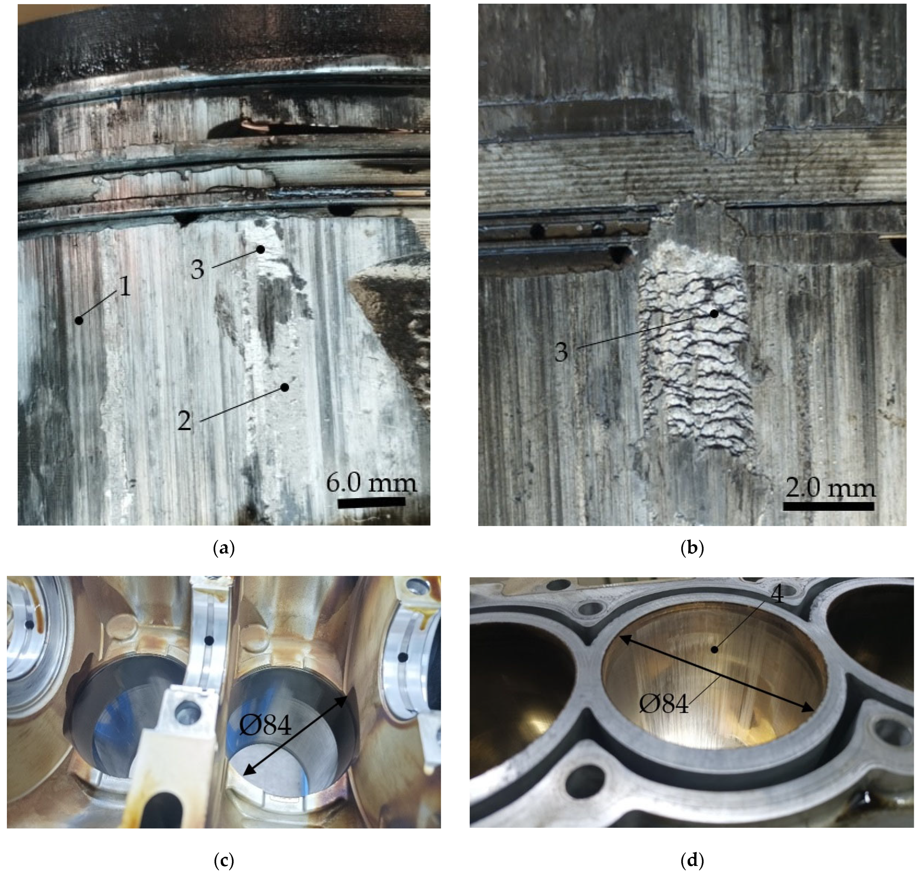
The ICE piston’s surface of the Kia Sportage car was inspected visually. Operational damage surface images (Figure 2) were obtained using the Canon EOS 1300D camera (Canon, Tokyo, Japan) at room temperature. As seen, the surface layers contain friction structures formed due to high contact loads and adhesion between the contact pair’s surfaces. This brought the surface material in the contact zone into a highly agitated state, which would not typically occur under ordinary deformation or thermal exposure alone. Fluctuations caused by a short-term deviation from the steady operating conditions account for such states of the surface.
We consider typical damage caused to the ICE piston’s surface of the Kia Sportage car and determine the staged nature and location of defects, as seen in Figure 2.
Spots occur due to differences in the wear intensity on different sides of the piston, caused by the gradient of loads on the liner surface over the cycle. In addition, fuel residues may condense on the liner surface, washing away the oil layer. As a result, a defect occurs on the liner and/or piston surface.
Scratches and dashes appear on the liner surface when particles enter the liner. The piston surface is also damaged.
Burrs and adhesions result from violations in the formation of mixture in the cylinder liner, or loss of tightness in the intake tract. Such malfunctions of the engine do not disturb its operation. However, long-term operation with an “over-lean mixture” causes a jump-like movement of the piston. As a result, the piston gets overheated, and burrs occur on the cylinder wall. Moreover, adhesions may appear, an example of which is shown in Figure 2.
With an excessive amount of abrasive materials in the lubricant, during the operation of the sleeve–piston friction pair, defects in the form of scratches, zone 1, first appear (Figure 2a). Similarly, defects in the form of scratches are formed on the inner cylindrical surface of the sleeve (Figure 2d). With further operation, the number of defects in the form of scratches increases, forming a friction zone 2 on the outer cylindrical surface of the piston, which subsequently evolves into an adhesive bonding zone 3.
Such in-service defects occurred in the car after a mileage of 80 thousand km. This is significantly less than the declared service life. Therefore, we can presume that the above defects resulted from failure to comply with the operating instructions. Since the ICE piston of the Kia Sportage car attained its ultimate state due to adhesions, the authors describe their nature in greater detail. As already noted, adhesions result from high specific pressures and such operating temperatures, at which the temperature threshold for the formation of adhesions between the surfaces of the friction pair is low. Wear products, which are normally present in the lubricant used in the contact zone of the friction pair, contribute to the formation of adhesions. Under such conditions, the surface of the friction pair has a relatively low resistance to shear plastic deformation. A heavily deformed friction layer can be seen on the surface. This suggests that the material “yields” under the influence of the counter body. Damage types caused to the ICE piston of the Kia Sportage car are summarized in Table 1.
In the contact points, the material was subjected to plastic deformation and shear along the liner wall, as long as the deformation resistance due to riveting did not exceed the adhesion forces of the surfaces.
Investigations into the damaged ICE piston’s surface of the Kia Sportage car suggest that the friction pair’s behavior under critical loads largely depends on the properties of its surface layers rather than on the bulk material itself.
To prevent these defects, a regular microrelief is proposed to be applied to the internal working cylindrical surface of the internal combustion engine and the piston’s O-rings. Such surface microtopography will allow reducing the temperature threshold for adhesion by 85 °C [11]. In other words, the friction process will be stabilized, that is, the average friction parameters and surface characteristics will become stable over time.

2.2. Technological Aspects of Applying a Regular Microrelief

Prevention of the formation of the above-described defects is based on the theory developed by Y.G. Schneider [11]. One of the postulates of the theory is that the formation of a regular microrelief on the working surfaces of a friction pair increases their oil capacity, due to the formation of “lubricating micropockets”. This provides a liquid regime of surface friction and prevents the formation of the above-described defects. To ensure maximum oil capacity of the surface and minimum wear compared to the honed surfaces of cylinder liners, it is recommended to form type II regular microrelief on the ICE liner’s inner surface. Moreover, the relative area of microrelief should be 32.7% [11]. The paper by [14] considers the optimal technological parameters, which provide for the maximum oil capacity of the surface with a regular microrelief applied onto it. The maintainable feed rate is 1000 mm/min.
Therefore, to prevent adhesions, the liner processing technology should be changed from honing to rolling. Type II regular microrelief should then be applied onto the inner cylindrical surface of the liner. Due to honing, the surface roughness parameter Ra fits within the range of 0.63–0.04 μm (Table 2). If we replace honing by applying RMR, the specified surface roughness parameter will not be provided, since the regular microrelief applied onto the surface reduces its roughness by only a few units. Once the RMR is applied, the surface roughness becomes dependent on the processing conditions during the previous operation.
For the best effect, regular microrelief should be formed on both surfaces of the friction pair, that is, on the inner surface of the liner and on the outer surface of the compression rings [15].
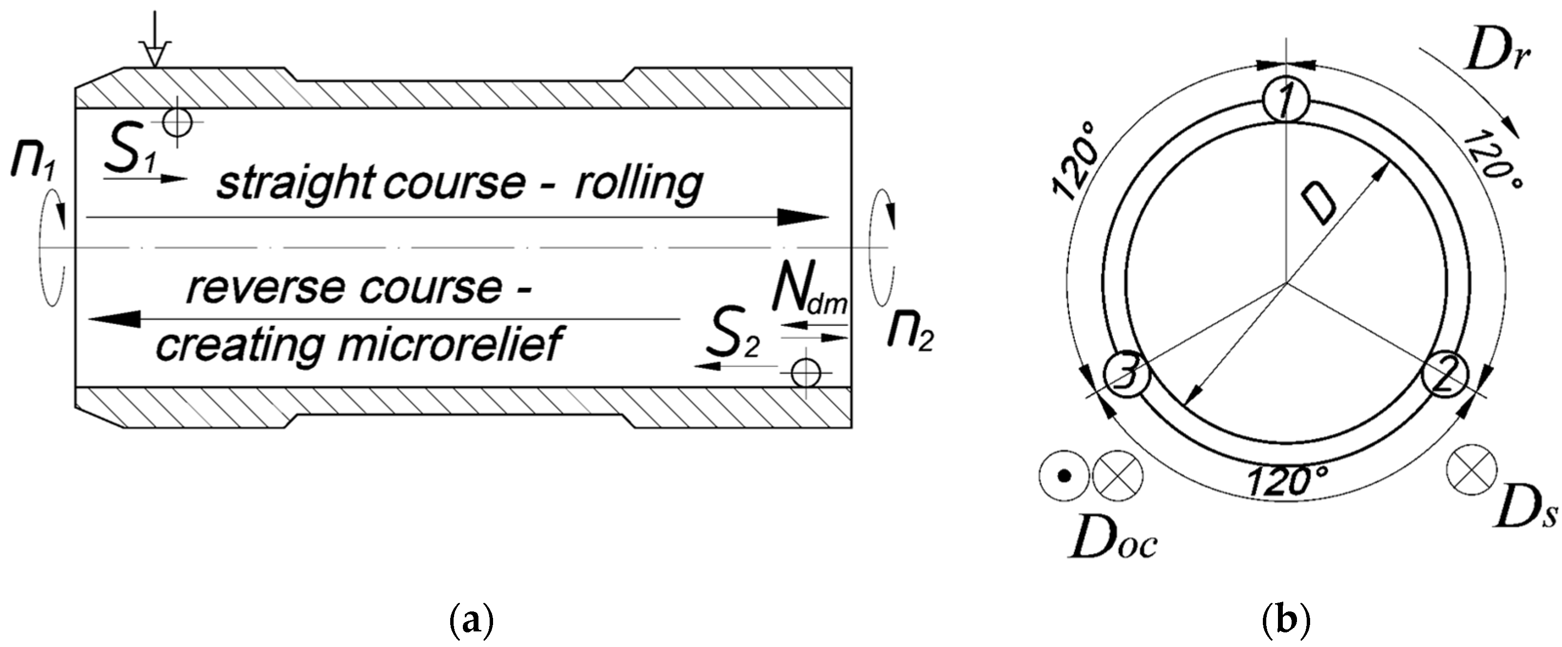
Figure 3 shows a movement cyclogram of deforming elements in the process of rolling the liner’s inner cylindrical surface on the forward stroke and when forming regular microrelief on the reverse stroke. To create a regular microrelief on the liner’s inner cylindrical surface, which was previously subjected to rolling, only one tool should be used in different modes.

2.3. Technology, Its Mathematical Model, and a Tool for Forming a Regular Microrelief

The basics of the technology for forming microreliefs on internal cylindrical surfaces were developed a relatively long time ago [16,17] and were gradually improved by taking into account the mechanisms of plastic deformation of the surface layers of metal by deformable elements [18,19,20].
Figure 3 shows a schematic diagram of the tool for creating a regular microrelief and the arrangement of deforming elements. The tool consists of three deforming elements placed 120ʰ apart. To visualize the regular microrelief created by the tool, Figure 3b presents a scan of the inner cylindrical surface of the cylinder liner.
Due to a combination of movements, namely rotation of the workpiece Dr, which is defined by the number of workpiece revolutions nw, progressive parallel movement along the longitudinal axis of the deforming elements Ds, which is defined by the feed rate S, and oscillatory motion Doc, which is defined by the number of oscillations Nosc, various types of regular microrelief can be created on the inner cylindrical surface of the cylinder liner.
The following dependencies can describe the main relationships between the above deformation movements and the geometric parameters of the microrelief grooves. The movement trajectory of the deforming element’s center (the ball) is a sinusoid, which is described by the equation
f 0 x = A sin ω t + φ
where A is the sinusoidal amplitude, ω is the angular frequency, and φ is the initial phase.
The coordinates of the equidistant that form the parametric profile of grooves in the OX1Y1 coordinate system are as follows:
x в = x o + ρ sin φ y в = y o + ρ cos φ , x н = x o ρ sin φ y н = y o ρ cos φ
where x0 and y0 are the current coordinates; ρ is the equidistant parameter equal to half width b of the groove, that is, ρ = b/2; and θ = a r c t g S / π D is the angle of inclination of the tangent determined at point О with respect to axis ОХ1 in the OX1Y1 coordinate system.
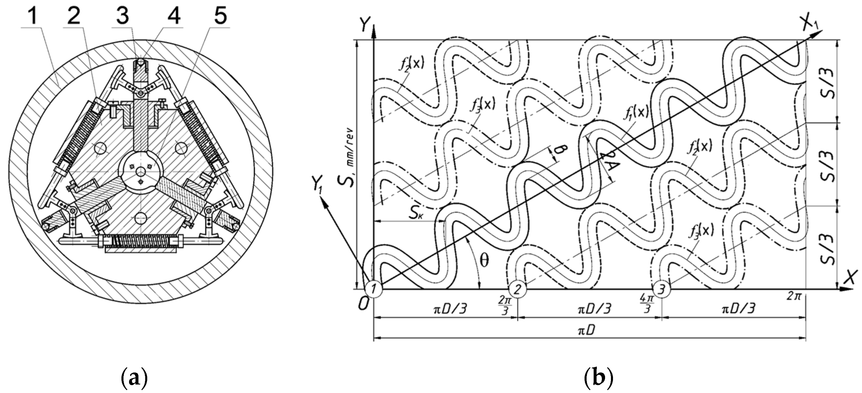
The microrelief formation process taking place on cylindrical surfaces has certain features. With two deforming movements, Dr and Doc, the deforming elements of the tool create a single groove, the axis of which is circular. Moreover, it coincides with segment ОВ in the scan of the cylinder surface (Figure 3b). Depending on the mutual arrangement of microrelief grooves (parallel grooves or those shifted by 0.5 of a step), the tool creates a certain number (an integer or multiple of 0.5) of groove elements in one revolution of the workpiece Nel. This is an obligatory condition for obtaining a regular microrelief. If the circle length is l c = π D , the condition that provides for the regularity of microrelief grooves will have the following form (provided that the groove’s axis is circular):
Nel = π·D·T
where Nel is the number of groove elements created in one revolution of the workpiece, and T is the step of grooves.
For a microrelief with parallel grooves, this number should be an integer; for a microrelief with grooves shifted by 0.5 of a step, this number should be a multiple of 0.5.
However, when all deforming movements are used (Dr, Di, and Dosc), the deforming elements create a groove on the cylinder surface, the axis of which has the form of a spiral. In addition, it coincides with segment S1 in the scan of the cylinder surface (Figure 3b). The length of segment OB1 is greater than that of segment OB. Therefore, to provide for the regularity of microrelief grooves, the number of elements of microrelief grooves Nel, which will be formed on this segment, should be an integer or multiple of 0.5:
N e l = S 2 + π D 2 T
A sinusoid is a periodic function with a period of 2π. This means that a deforming element will create a groove in the form of a continuous sinusoidal wave in one revolution of the workpiece. A microrelief groove with such geometry has little effect, since many more waves are required to provide for certain operational properties. The parameter ω is introduced in Equation (1) to control the frequency of grooves. The relationship between this parameter and the number of microrelief elements created in one revolution of the workpiece is described by the following relationship:
ω = 2 π N e l S 2 + π D 2
A regular microrelief determined by such kinematics was provided by a certain ratio between values A and b. In this case, the so-called “special points”, in which the derivative has two different values, do not appear on the curved lines.
A mathematical model of type II regular microrelief is expressed in the following form:
y 01 = A sin ω x ; y 02 = A + sin ω x 1 + π n з N o с ц S ¯ 3 cos a r c t g S ¯ π D ;   2 π 3 x 1 2 π ; y 02 = A + sin ω x 1 + π n з N o с ц + 2 S ¯ 3 cos a r c t g S ¯ π D ;   0 x 1 2 π 3 ; y 03 = A + sin ω x 1 2 S ¯ 3 cos a r c t g S ¯ π D ;   4 π 3 x 1 2 π ; y 03 = A + sin ω x 1 + S ¯ 3 cos a r c t g S ¯ π D ;   0 x 1 4 π 3 .
i = N o с ц / 3 n з + 0.5 φ = S к / 2 A = S 6 1 + S / π D 2 b 2 .
where Nosc is the oscillation frequency measured in double strokes per minute; nw is the workpiece rotation rate, rpm; and Ss is the angular step of the groove.
Depending on the specified geometric microrelief parameters (A, b, Sk) and conditions, under which microrelief is formed (S, Nosc, nw), Formula (6) can be used to obtain the center line coordinates of the continuous regular microrelief’s grooves. Figure 4a shows how the scheme in Figure 3 is implemented in practice. The results obtained help create the specified types of regular microrelief on the outer cylindrical surfaces, as shown in Figure 4b.
The tool is installed in the opening of cylinder liner 1. Its body 2 has radial holes, in which guiding rods 3 are arranged 120° apart. Deforming elements 4 are placed at the end of the rods. Cam 5 serves to create force on deforming elements 4.

3. Results and Discussion

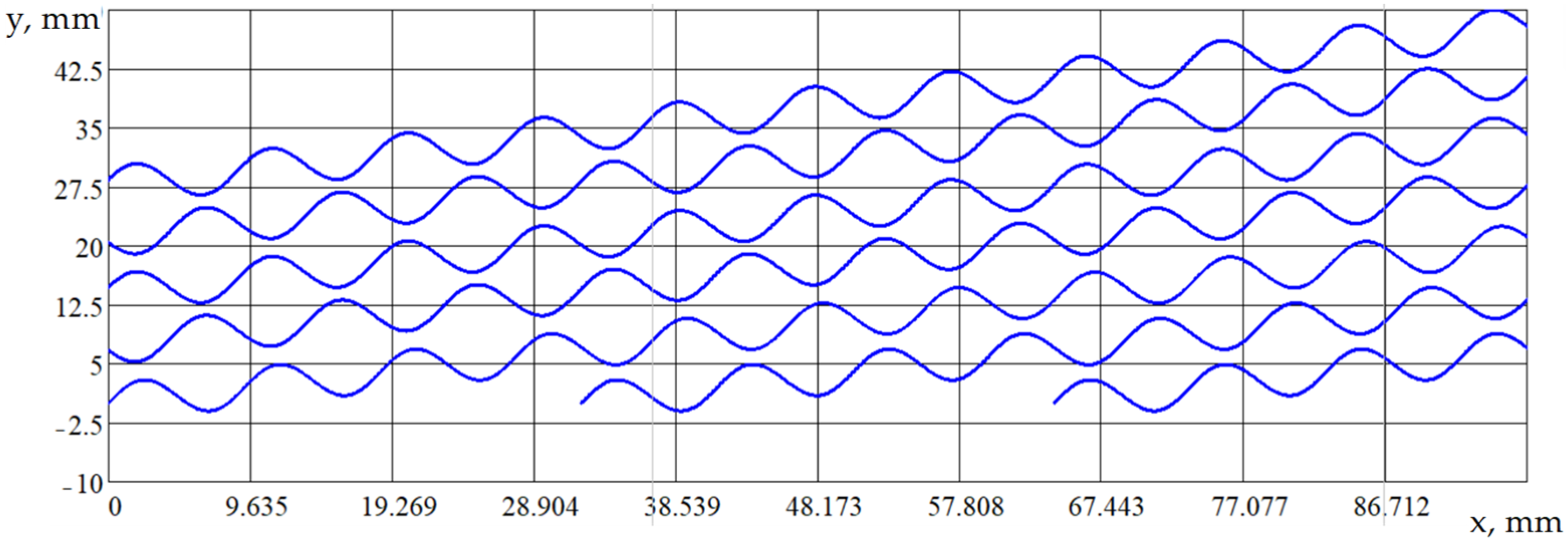
Analytical model (6) was programmed in MathCAD, and the centerlines of continuous regular microirregularities were obtained. They have the following parameters: A = 2.5 mm; S = 20 mm/rev; and Nosc = 10; D = 30 mm. These lines are sinusoidal. They allowed us to make a scan of the cylinder liner’s surface using the method of rotating the coordinate axes (see Figure 5).
It is noteworthy that the optimal area of microrelief grooves Fk was in the range of 25–45%. This holds true for all cases, regardless of the patterns and methods of applying the “drawing”. Lower Fk values provide for a scarce oil capacity of the mating surfaces, while higher ones account for a significant decrease in their load-bearing capacity. In particular, A.S. Lichkovaha [21] has found certain Fk values for a pair of ZMZ-53 engines. The internal cylindrical surfaces of ICE cylinder liners, to which type I microrelief with non-mating grooves was applied, have the groove area Fk = 32.7%. Liner surfaces treated by burnishing have a much higher (2–4-fold) wear resistance than those treated by honing.
Yu. G. Schneider and G.G. Lebedinsky [22,23,24] studied the liners of the M-412 engine, for which type I microrelief with a groove area of 44.8% appears optimal. Once applied, such microrelief provides for a 1.5–1.7-fold increase in wear resistance. Similar findings obtained by A.N. Isaev [10,19] are available, which deal with the liners of ZIL-130 engines. Type I microrelief, which is believed to be optimal, had the groove area Fk = 45%, which provided for a 1.5–2.0-fold increase in wear resistance.
New models of type II regular microrelief are applied to the inner cylindrical surfaces of ICE cylinder liners. They provide for a system of grooves. The proposed system of relief formations will help retain grease in the contact zone and distribute it over the entire surface of the ICE liner [25,26,27,28,29]. This will:
-
Extend the service life and reliability of operation;
-
Reduce friction losses;
-
Make the mutual movement of surfaces smoother;
-
Enhance contact stiffness;
-
Extend fatigue life;
-
Enhance corrosion resistance.
Optimal lubrication conditions will prevent ICEs from developing scuff marks, adhesions, and other phenomena that occur upon contact between the surfaces of mating parts of the ICE units during operation.

4. Conclusions

This paper analyzes the causes that lead to the failure of ICE cylinder units. Non-compliance with operating instructions is identified as the primary cause of adhesion-related defects. Technological solutions are proposed to prevent such technological failures. In particular, the finishing operation of the ICE cylinder liners’ manufacturing technology should be changed. The authors propose to replace honing by rolling, followed by the formation of type II regular microrelief on the liner surface. Analytical dependencies are obtained, which simulate the movement of the tool’s deforming elements in the process of creating type II regular microrelief. Geometrical parameters of the microrelief grooves and processing conditions are also considered.
Mathematical models have been developed that allow us to estimate the geometry of an ordered surface microrelief based on the specified parameters. A PC program was developed for the first time, which makes it possible to graphically visualize the results of applying microrelief. This is an obligatory condition for improving processing parameters.

Author Contributions

Conceptualization, V.D. and P.M.; methodology, V.D.; analysis and validation, V.D. and P.M.; writing, V.D., P.M., R.B., R.K., V.T., and A.M.; review and editing, V.D.; supervision, P.M. All authors have read and agreed to the published version of the manuscript.

Funding

This research received no external funding.

Institutional Review Board Statement

Not applicable.

Informed Consent Statement

Not applicable.

Data Availability Statement

The data presented in this study are available on request from the corresponding author.

Conflicts of Interest

Author Abdellah Menou was employed by the company National Airports Authority of Morocco. The remaining authors declare that the research was conducted in the absence of any commercial or financial relationships that could be construed as a potential conflict of interest.

References

  1. Fedorchenko, V.I.; Olkhov, V.S.; Panasenko, O.M. Expert research on the establishment disturbances causes of tribounits of internal combustion engines. Theory Pract. Forensic Sci. Crim. 2018, 18, 399–405. [Google Scholar] [CrossRef]
  2. Liu, Q.; Huang, X.; Shao, X.; Hao, F. Industrial cylinder liner defect detection using a transformer with a block division and mask mechanism. Sci. Rep. 2022, 12, 10689. [Google Scholar] [CrossRef] [PubMed]
  3. Li, C.; Chen, X.; Liu, H.; Dong, L.; Jian, H.; Wang, J.; Du, F. Tribological Performance and Scuffing Resistance of Cast-Iron Cylinder Liners and Al-Si Alloy Cylinder Liners. Coatings 2023, 13, 1951. [Google Scholar] [CrossRef]
  4. Mallick, A.; Setti, S.G.; Sahu, R.K. Centrifugally cast functionally graded materials: Fabrication and challenges for probable automotive cylinder liner application. Ceram. Int. 2013, 49, 8649–8682. [Google Scholar] [CrossRef]
  5. Grabon, W.; Pawlus, P.; Wos, S.; Koszela, W.; Wieczorowski, M. Evolutions of cylinder liner surface texture and tribological performance of piston ring-liner assembly. Tribol. Int. 2018, 127, 545–556. [Google Scholar] [CrossRef]
  6. Koszela, W.; Pawlus, P.; Reizer, R.; Liskiewicz, T. The combined effect of surface texturing and DLC coating on the functional properties of internal combustion engines. Tribol. Int. 2018, 127, 170–477. [Google Scholar] [CrossRef]
  7. Zhan, X.; Yi, P.; Liu, Y.; Xiao, P.; Zhu, X.; Ma, J. Effects of single- and multi-shape laser-textured surfaces on tribological properties under dry friction. Proc. Inst. Mech. Eng. Part C J. Mech. Eng. Sci. 2020, 234, 1382–1392. [Google Scholar] [CrossRef]
  8. Feodosyev, V.I. Strength of Materials: Textbook; Nauka: Moscow, Russia, 1970; 544p. [Google Scholar]
  9. Rosenberg, A.M.; Rosenberg, O.A. Mechanics of Plastic Deformation in Cutting and Deforming Drawing Processes; Naukova Dumka: Kiev, Ukraine, 1990; 330p. [Google Scholar]
  10. Isaev, A.N. Mechanical diagram of deformation of a tubular blank in the process of mandrel breaking. Forg. Stamp. Prod. 2001, 4, 6–11. [Google Scholar]
  11. Shneider, Y.U.G. Service Properties of Parts with Regular Microrelief, 2nd ed.; Revised and Augmented; Mashinostroenie: Leningrad, Russia, 1982; 248p. (In Russian) [Google Scholar]
  12. Zhao, M.; Li, W.; Wu, Y.; Zhao, X.; Tan, M.; Xing, J. Performance Investigation on Different Designs of Superhydrophobic Surface Texture for Composite Insulator. Materials 2019, 12, 1164. [Google Scholar] [CrossRef] [PubMed]
  13. GOST 24773-81; Surfaces with Regular Microshape. Classification, Parameters and Characteristics. Izdatelstvo Standartov: Moscow, Russia, 1988.
  14. Dzyura, V.; Maruschak, P.; Slavov, S.; Dimitrov, D.; Semehen, V.; Markov, O. Evaluating Some Functional Properties of Surfaces with Partially Regular Microreliefs Formed by Ball-Burnishing. Machines 2023, 11, 633. [Google Scholar] [CrossRef]
  15. Dzyura, V.O.; Lyashuk, O.L. Cylinder-Piston Mechanism of an Internal Combustion Engine. Patent of Ukraine No. 138496 F02B 77/00, Bull. No. 22, 25 November 2019. [Google Scholar]
  16. Proskuryakov, Y.G. Burnishing of Cylindrical Holes with Greater Interference; Rostov University Publishing House: Rostov-on-Don, Russia, 1982; 166p. [Google Scholar]
  17. Leshnekova, L.R. Increasing the Productivity of the Process and Improving the Operational Properties of the Surfaces of the Holes by the Method of Surface Plastic Deformation with the Formation of a Regular Microrelief; Cand. of Technical Sciences Dissertation: Saratov, Russia, 2002; 184p. (In Russian) [Google Scholar]
  18. Slater, R.A.C. Plane Strain Plastic Deformation. In Engineering Plasticity; Palgrave: London, UK, 1977. [Google Scholar] [CrossRef]
  19. Isaev, A.N. Elastic restoration of hole patterns after mandrel boring of tubular blanks. Bull. DSTU 2004, 4, 437–442. [Google Scholar]
  20. Khayatzadeh, S.; Rahimi, S.; Blackwell, P. Effect of Plastic Deformation on Elastic and Plastic Recovery in CP Titanium. Key Eng. Mater. 2016, 716, 891–896. [Google Scholar] [CrossRef]
  21. Lichkovaha, A.S. Improving the Quality of Finishing of Repaired Cylinder Liners of Internal Combustion Engines; Cand. of Technical Sciences Dissertation: Zernograd, Russia, 2007; 215p. (In Russian) [Google Scholar]
  22. Schneider, Y.G.; Feldman, Y.S.; Lebedinsky, G.G. Vibration rolling of surfaces with a multi-ball tool. Mach. Tools 1973, 7, 36–37. [Google Scholar]
  23. Schneider, Y.G.; Lebedinsky, G.G.; Ivanov, I.A. Study of the influence of oil absorption of working surfaces of ZIL-130 engine cylinder liners on the dynamics of their wear. Automot. Ind. 1973, 7, 7–8. [Google Scholar]
  24. Schneider, Y.G.; Lebedinsky, G.G.; Bunga, G.A.; Gutin, M.E. Study of the dependence of cylinder liners wear resistance on the microrelief of the working surface. Automot. Ind. 1970, 2, 41–42. [Google Scholar]
  25. Guzanová, A.; Brezinová, J.; Bronček, J.; Maruschak, P.; Landová, M. Study of selected properties of coatings devoted to extreme tribo-corrosive conditions. Mater. Sci. Forum. 2015, 818, 32–36. [Google Scholar] [CrossRef]
  26. Volchok, A.; Halperin, G.; Etsion, I. The effect of surface regular microtopography on fretting fatigue life. Wear 2002, 253, 509–515. [Google Scholar] [CrossRef]
  27. Shahzad, A.; Haque, U.U.; Lazoglu, I. Effect of the micro-textured piston on the performance of a hermetic reciprocating compressor. Proc. Inst. Mech. Eng. Part J J. Eng. Tribol. 2023, 237, 1107–1118. [Google Scholar] [CrossRef]
  28. Bai, L.; Sun, J.; Zhang, P.; Khan, Z.A. Friction Behavior of a Textured Surface against Several Materials under Dry and Lubricated Conditions. Materials 2021, 14, 5228. [Google Scholar] [CrossRef] [PubMed]
  29. Annadi, R.R.; Syed, I. Impact of multi-scaled surface textures on tribological performance of parallel sliding contact under lubricated condition. Tribol. Int. 2023, 183, 108415. [Google Scholar] [CrossRef]
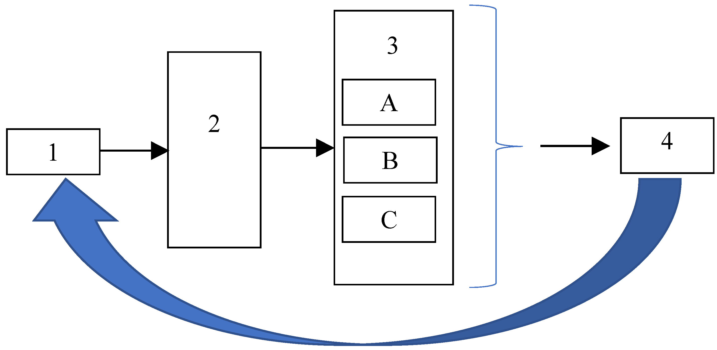
Figure 1. Scheme for investigating the ICE piston’s surface damaged during operation and technology for applying the ordered relief on the rotation surface: 1—part inspection; 2—identification of in-service damage; 3—classification of in-service damage (A, B, C defect types); 4—technology for increasing oil capacity.
Eng 06 00152 g001
Figure 2. Operational damage to the elements of the cylinder-piston group of the Kia Sportage car manufactured in 2022: general view of the in-service damaged piston (a); image of the nature of damage-adhesions between the surfaces of the liner and the piston (b); general view of the damaged cylinder block of the engine (c); scuffing of the cylinder liner surface (d); 1, 4—scratches, zone; 2—friction zone; 3—bonding zone; 4—scuffs.
Eng 06 00152 g002
Figure 3. Movement cyclogram of deforming elements in the process of rolling the liner’s inner cylindrical surface on the forward stroke and when forming a regular microrelief on the reverse stroke (a); using deforming elements consisting of balls (b).
Eng 06 00152 g003
Figure 4. Rolling the inner cylindrical surface of the cylinder liner (a); and forming a regular microrelief on it with a new tool (see the scan) (b) 1—cylinder liner, 2—tool case, 3—pusher, 4—ball, 5—ratchet.
Eng 06 00152 g004
Figure 5. Mathematical models of the groove axes of type II regular microrelief realized in MathCAD. Grooves are formed on the scan, which shows the inner cylindrical surface of the ICE cylinder liner (A = 2.5 mm; D = 30 mm; S = 20 mm/rev; n = 10 waves/rev.).
Eng 06 00152 g005
Table 1. Damage types caused to the ICE piston.
State of the Working SurfaceDefects on the External Surface of the ICE Piston
Stains ScratchesBurrs and Grips
It is a critical state of the part+
Table 2. Comparative analysis of technologies for finishing the inner cylindrical surface of ICE liners.
Advantages Provided by TechnologyFine TurningHoningRoll OutCreation of RMPTurning with Creation of RMP
Surface roughness, Ra1.25…0.630.63…0.040.4…0.051.25…1.000.63…0.05
Strengthening of the surface--+++
Increase in oil capacity-+-++
Disclaimer/Publisher’s Note: The statements, opinions and data contained in all publications are solely those of the individual author(s) and contributor(s) and not of MDPI and/or the editor(s). MDPI and/or the editor(s) disclaim responsibility for any injury to people or property resulting from any ideas, methods, instructions or products referred to in the content.