Article

Techno-Economic Analysis of the Implementation of the IEC 62034:2012 Standard—Automatic Test Systems for Battery-Powered Emergency Escape Lighting—In a 52.8-Meter Multipurpose Vessel

by
Luis García Rodríguez
1,2,
Laura Castro-Santos
3 and
María Isabel Lamas Galdo
3,*
1
Escuela Técnica Superior de Ingenieros Industriales y de Telecomunicación, Universidad de Cantabria, Avda de los Castros s/n, 39005 Santander, Spain
2
Escola Politécnica de Enxeñaría de Ferrol (EPEF), Universidade da Coruña, C/Mendizábal s/n, 15403 Ferrol, Spain
3
Escola Politécnica de Enxeñaría de Ferrol (EPEF), Universidade da Coruña, Campus Industrial de Ferrol (ClF), Centro en Tecnoloxías Navais e Industriais (CITENI), 15471 Ferrol, Spain
*
Author to whom correspondence should be addressed.
Eng 2025, 6(6), 110; https://doi.org/10.3390/eng6060110
Submission received: 8 April 2025 / Revised: 21 May 2025 / Accepted: 22 May 2025 / Published: 23 May 2025

Abstract

:
This study aims to evaluate the techno-economic feasibility of implementing the IEC 62034:2012 standard, which governs automatic test systems for battery-powered emergency escape lighting, on a 52.8-m multipurpose vessel. The work is based on a detailed case study of the vessel’s lighting systems, incorporating lighting simulations, system modifications using DALI-compatible components, and an economic analysis based on net present value, internal rate of return, and discounted payback period. The results demonstrate that the implementation reduces preventive maintenance costs significantly—from 24,750 EUR to 2250 EUR over ten years—while achieving a positive net present value of 5317 EUR, an internal rate of return of 27.81%, and a discounted payback period of under five years. The findings contribute to maritime safety literature by extending the application of IEC 62034:2012 to shipboard environments, where it is not yet standard practice. Practically, it provides a cost-effective and safety-enhancing solution for ship operators, suggesting that automated testing systems can replace outdated manual maintenance procedures and improve compliance with safety regulations.

1. Introduction

The lighting system on a ship is made up of three distinct and separate networks.
-
Main lighting is supplied by the ship’s main electrical power sources.
-
Emergency lighting is supplied by the ship’s emergency electrical power source. If the main power supply is interrupted, the required emergency lighting automatically switches on.
-
Emergency escape lighting, also known as escape lighting or transitional lighting, is a part of emergency lighting designed to help people safely exit a facility during an emergency situation. It is powered by a battery backup (transitional) source of electrical power. The escape lighting system activates automatically in the event of failure of the main and emergency power sources. This type of escape lighting is mandatory on ships where the emergency power supply does not automatically connect to the main emergency busbar within 45 s or on vessels classified as passenger ships and ferries [1].
Escape lighting is safety lighting that is used to illuminate safe escape routes and facilitate visibility, as well as indicate the direction of the escape route. It is also used as anti-panic lighting. This lighting is activated when the vessel experiences a blackout, so regular maintenance and testing are essential, as it only operates in the event of a failure [2,3,4]. A well-designed lighting environment improves safety and comfort aboard ships [5].
Escape lighting is connected to the emergency power supply and provides transitional lighting until the emergency generator starts and carries on connected to the main emergency busbars when the emergency switchboard is powered and supplied by the emergency source [6]. This type of escape lighting is based on the fact that it does not depend on the ship’s electrical networks (mains or emergency) but on an independent battery source that guarantees it for a period of time [7,8,9]. According to the manufacturer’s datasheet, this period is usually one or three hours. These batteries can be integrated into the luminaires themselves or via centralized battery systems (uninterruptable power supply, UPS). Preventive maintenance of this escape lighting has traditionally relied on manual tests, which are now considered obsolete and are often omitted to reduce maintenance costs [10].
The standards upon which ship construction is based and define the operation and installation of a vessel’s lighting system are the standards set by Classification Societies, SOLAS, and the regulations of the Flag Authorities. Upon the completion of the vessel’s construction, the responsibility for maintaining the system in accordance with the operational conditions outlined in these regulations falls to the shipowner, thereby rendering the implementation of appropriate preventive maintenance indispensable, as indicated in IEC 62034:2012. It is crucial to emphasize that, in contrast to onshore structures, a ship operates in an environment that is both highly aggressive and corrosive, subject to the forces of waves and tides. This exposure accelerates the deterioration of these installations unless proper maintenance is consistently carried out.
The IEC 62034:2012 standard [11]—automatic test systems for battery-powered emergency escape lighting—outlines the performance and safety requirements for automatic test systems used in emergency lighting systems operating at voltages of up to 1000 V. It covers the monitoring of timing circuits, functional requirements, handling of components, and software failures. It also specifies the necessary functional and duration tests to ensure the reliability and safety of the system. This standard is essential for maintaining the effectiveness of emergency lighting systems during power outages or emergencies. The IEC 62034:2012 standard is based on the development of an automatic test system for battery-operated escape luminaires (centralized or individual), in which the escape luminaires are tested in a reliable and safe manner through scheduled tests, providing information on individual failures of each luminaire and the escape lighting system itself. This allows the generation of the necessary information to guarantee the correct functioning of the installed escape luminaires when required. To this end, the standard identifies the performance of the following two tests.
  • Functional test: A test to check the integrity of the circuit and the correct operation of a luminaire, the changeover device, and the backup battery. A functional test shall be performed at least once a month.
  • Duration test: A test to check whether the backup battery power supply source provides the system with power for the rated duration of emergency operation. A functional test shall be performed at least once a year.
In addition, a remote control station always provides information on the status of each luminaire. That said, this standard requires human action for corrective maintenance.
The incorporation of automated control systems has an important potential to improve navigation safety [12]. Regarding the escape lighting system, traditional testing methods predominantly depend on manual procedures, rendering them vulnerable to oversight and human error. These inherent shortcomings can be effectively mitigated through the implementation of automated testing systems. In the context of escape luminaires, it is imperative that such systems execute tests with consistency and ensure timely reporting of any functional failures or performance deterioration.
Techno-economic analyses of escape lighting on ships are crucial for improving safety in emergencies while taking into account the economic implications of different lighting technologies. A key consideration in these analyses is the transition from traditional lighting systems to more advanced technologies, such as LED lighting. Currently, LED lighting has replaced outdated, inefficient, and polluting fluorescent lighting in shipbuilding for several reasons, including reduced costs of generating electrical energy, an increased useful lamp life with consequently reduced maintenance costs, ease of regulation, and access to information on the status of the driver and lamp, as well as control and monitoring of the luminaires [13,14]. Recent studies have highlighted the benefits of replacing traditional lighting systems with LED technology. For example, Sędziwy et al. [15] emphasize the financial benefits of energy-efficient installations, noting that retrofitting existing systems can lead to significant cost savings over time due to reduced energy consumption and maintenance costs. These findings are consistent with those of Salata et al. [16], who discuss energy optimization in lighting systems and suggest that the initial investment in advanced lighting technologies can be offset by long-term savings and improved operational efficiency.
Wati et al. [17] suggest that integrating LED technology into ship lighting systems can significantly improve operational efficiency and sustainability. LEDs consume less power and have a longer lifespan than conventional lighting, resulting in lower maintenance and replacement costs over time. Furthermore, Suardi et al. [18] demonstrate that using LED lamps can reduce generator power requirements on ships, thereby decreasing fuel consumption and associated operational costs. This reduction in energy demand lowers expenses and contributes to a ship’s overall environmental sustainability. Even the classification societies have adapted their rules to include LED technology, incorporating a section on lighting based on controllers into their standards [19]. Other authors proposed energy-efficient lighting systems for ships based on solar-powered systems [20] and integrated smart technologies into escape lighting systems, such as intelligent lighting controls that optimize energy use and enhance safety by adjusting lighting levels based on real-time conditions [21,22]. This adaptability improves safety outcomes and contributes to further cost savings through efficient energy management. Lin et al. [23] emphasize that shipping companies’ financial performance can be enhanced through investment in energy-efficient technologies, leading to reduced operational costs and improved safety measures. This aligns with the findings of Wang and Lee [24], who emphasize the importance of evaluating financial performance using various indices. They suggest that companies investing in efficient technologies may achieve a higher ranking in financial assessments. Furthermore, the initial investment in advanced lighting systems should be considered in relation to the long-term savings it will generate. Christodoulou et al. [25] discuss the economic impacts of regulatory frameworks, such as the EU Emissions Trading System, which can influence shipping companies’ operational costs. Implementing escape lighting systems that comply with safety regulations is a necessary investment that enhances safety and mitigates potential costs associated with non-compliance during inspections or emergencies.
The economic benefits of escape lighting go beyond direct savings. Effective lighting can enhance the overall safety of a vessel, which could potentially reduce liability and insurance costs. Jin and Schinas [26] observed that shipping companies that prioritize safety and compliance with regulations tend to be viewed more favorably by investors, leading to better financing opportunities. This aligns with the findings of Lin et al. [27], who stated that financial indicators play a vital role in attracting investment, particularly with regard to emergency preparedness and safety measures.
The present work analyzes the implementation of the 62034:2012 standard [11] in a multipurpose (MPV) vessel from a techno-economic perspective. Traditionally, emergency and escape lighting, which is mandatory on most merchant ships, has only been analyzed in terms of its power supply from the ship’s emergency source. The only consideration for shipowners, crew, and classification societies was that, in an emergency, the emergency and escape lighting would switch on automatically, generating the minimum required lux. This work demonstrates the advantages of implementing the IEC62034 standard, a standard that is not currently applied to ships, to reduce maintenance costs and, above all, to prevent failure due to human negligence in an emergency situation where failure could have serious consequences for the crew of the ship. It also aims to eliminate the need for outdated maintenance techniques, which are often obsolete due to a lack of time or resources. The IEC 62034:2012 standard primarily applies to land-based infrastructure and has seen extensive implementation in various sectors. Although its principles are transferable to maritime environments, its adoption in this sector remains limited. This underutilization highlights a critical research gap concerning the feasibility, benefits, and challenges of applying the standard aboard ships. Addressing this gap is essential for enhancing safety and operational efficiency in maritime settings, where reliable emergency lighting is vital.
A number of marine manufacturers provide comprehensive systems—encompassing everything from the control panel to the luminaires—incorporating protocols specifically tailored for escape lighting (DALI, KNX, DMX, and others), fully compliant with European regulations and standards. However, their primary limitations include the difficulty of interfacing with luminaires from other manufacturers, the restriction on the number of luminaires that can be installed, and also space problems given that the dimensions of the switchboards are fixed. The number of luminaires to be installed for each network of the ship was calculated, with a focus on those affected by the IEC 62034:2012 standard (escape luminaires), as well as the installed battery power. Some manufacturers of marine luminaries implemented their own monitoring systems. In this report, the DALI protocol is used so as not to depend on any manufacturer; installed naval luminaires only need to have a DALI driver. The manufacturer selected for the luminaires is the well-known manufacturer LIGHTPARTNER, but others can be used in combination with different manufacturers. An economic analysis of the necessary investment was carried out to analyze the following indicators: NPV (net present value), IRR (internal rate of return), and DPBP (discounted payback period) in order to analyze its feasibility. As exemplified in this case, the installed ATEX luminaires are distributed by LIGHTPARTNER, although they are not manufactured by this company. Other advantages of the DALI system compared to other protocols include the following.
  • Open Protocol: DALI is an open, standardized, and interoperable intelligent lighting control protocol developed in accordance with the international IEC 62386 standards [28].
  • System Compatibility: When all system components are DALI-compliant, seamless communication between them is ensured.
  • Simplified Wiring: DALI supports any topological structure except for ring configurations. Both the power supply to the luminaire and the control signal to the DALI driver can be transmitted through a single cable, with the signal line being non-polarized. Furthermore, no specialized cable types are required.
  • Scalability: Each master controller can manage up to 64 drivers, and the system can be scaled as needed by adding additional masters.
  • Extended Distance Capabilities: While the DALI bus has a theoretical maximum length of 300 m, this distance can be extended using appropriate devices.
  • System Integration: DALI can operate as a standalone control system or be integrated into an automation system. It provides a more precise and efficient control for lighting than KNX or DMX protocols.
Following this introduction, the present work continues with a Materials and Methods section, which details the case study and describes the ship analyzed, its onboard lighting systems, and the modifications required to implement the standard. The Results and Discussion section then presents the technical calculations, investment costs, and economic results to assess the feasibility. Finally, the Conclusions section highlights the benefits of adopting the standard, both in terms of safety and cost-effectiveness, and suggests directions for future research.

2. Materials and Methods

2.1. Case of Study

An MPV includes a wide variety of tonnage and length vessels which can support the following activities:
  • Oceanographic research;
  • Fisheries research;
  • Acoustic fisheries surveys;
  • Underwater TV surveys;
  • Ichthyoplankton surveys;
  • Hydrographic surveys;
  • ROV surveys;
  • AUV/ASV surveys;
  • Coring/grab sampling;
  • Drop camera;
  • Buoy/mooring operations.
Given the vessel’s operational profile, accommodation is designed for both crew and scientists (as well as other passengers). Since these scientists are not sailors, escape lighting is essential for their safety.
The LED lighting on this vessel, 
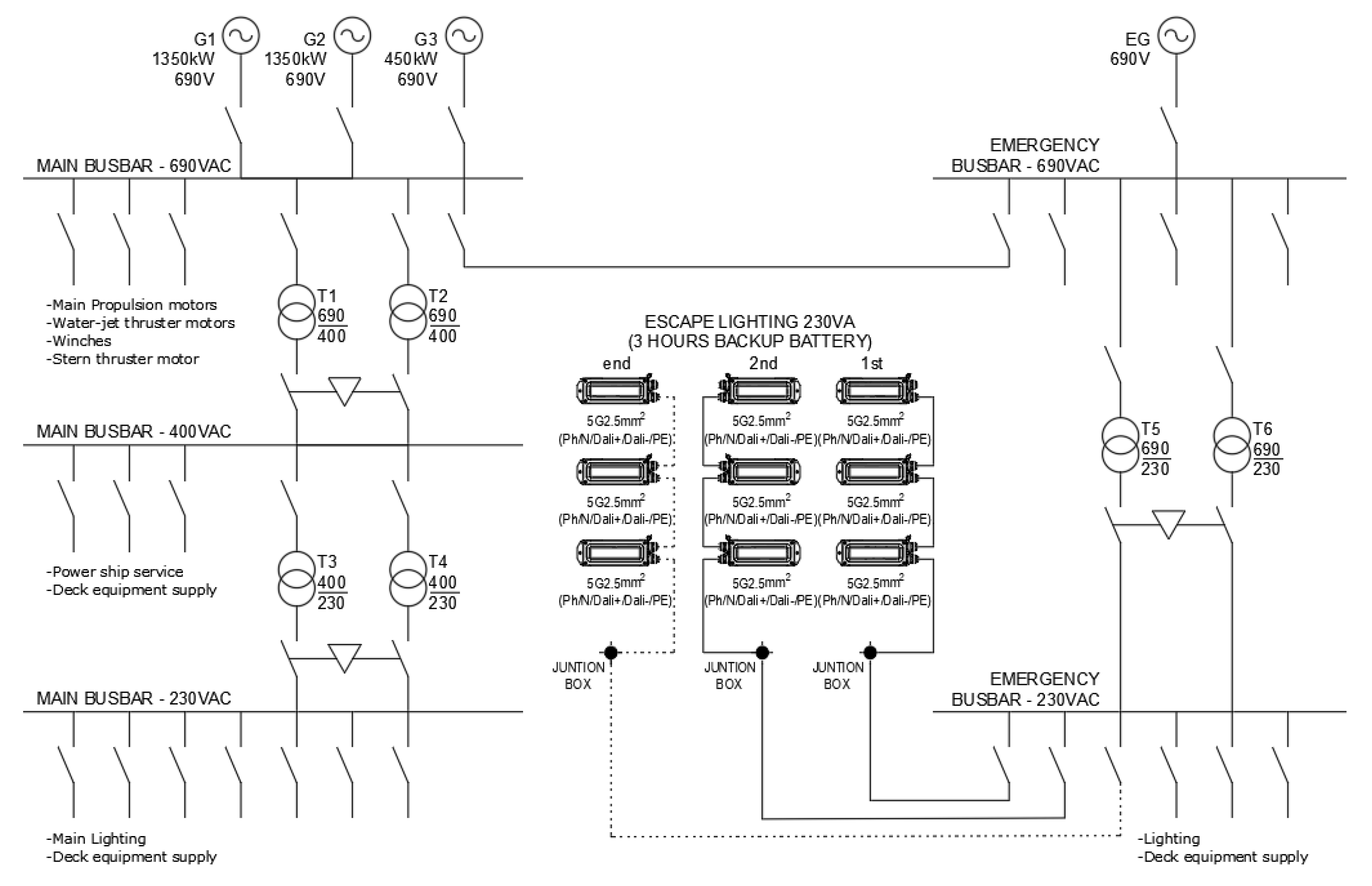
Figure 1, consists of the following systems.
  • Main Lighting System: The main lighting system is supplied from the main power supply system, which consists of three 690 V main generators (G1, G2, and G3) with the capability for parallel operation. Power is distributed via main step-down transformers 690/400 V (T1 and T2), which are not designed for parallel coupling, and each transformer has sufficient capacity to supply all 400 V consumers independently. The 230 Vac main switchboard and each sub-distribution switchboard are power supplied from the 400 V main switchboard via service transformers 400/230 V (T3 and T4), also without parallel coupling capability, each capable of independently supplying the entire 230 V load.
  • Emergency Lighting System: The emergency lighting system is powered by the emergency power supply (emergency generator EG) via the emergency transformers 690/230 V (T5 and T6). These transformers are not intended for parallel operation, and each is capable of supplying the full 230 V emergency load independently. Under normal operating conditions—when the main generators are connected to the main busbar—the emergency lighting is power supplied from the 690 Vac main switchboard via an interconnecting circuit breaker on 690 V bars.
  • Escape Lighting System: The escape lighting system is equipped with integral battery backup providing a minimum of 3 h of autonomy. These batteries are charged from the 230 V emergency busbar, either through the 230 Vac emergency switchboard or an onboard emergency sub-distribution board. The escape lighting is automatically activated in the event of failure of both the main and emergency power supply systems.
The dimensions of the MPV analyzed are shown in Table 1.
The ship must be adequately illuminated with the lighting levels required by national authorities and legislation [29] and minimum lighting levels measured at 700 mm above the deck, as indicated in Table 2.
According to the manufacturer’s instructions (Lightpartner Lichtsysteme GMBH & CO. KG, Bremen, Germany), the estimated standard useful life of this type of LED luminaire is 80,000 h, equivalent to around 10 years.

2.2. Economic Indicators

The economic viability of the proposal was assessed using economic parameters. To evaluate the economic feasibility, the cash flow was calculated over its useful life, along with the net present value (NPV), internal rate of return (IRR), and discounted payback period (DPBP).
The NPV represents the present value of the cash flows at the required rate of return on the economic savings generated by implementing the IEC 62034:2012 standard compared to the initial investment, Equation (1).
NPV = t = 1 n C F t ( 1 + r ) t
where CFt is the cash flow in year t, r is the discount rate r, and n is the number of time periods.
If the NPV is greater than 0, the investment will generate earnings above the required return (r). In this case, acceptance of the proposal is recommended. Conversely, if the NPV is less than 0, the investment will produce returns below the required minimum return (r), and the proposal should not be accepted. If NPV equals 0, the proposal does not generate additional monetary value beyond the required profitability (r), so the decision must be based on other criteria.
The IRR represents the interest generated by the proposal over its useful life. It is calculated as the discount rate that returns the NPV to zero (Equation (2)), meaning it is the interest rate that makes the future cash flows equivalent to the initial investment in financial terms.
0 = t = 1 n C F t ( 1 + IRR ) t
The economic feasibility of the proposal hinges on the IRR. If the IRR is less than the required rate of return (r), the proposal is not profitable enough to be considered a good investment. Conversely, if the IRR exceeds r, the proposal’s profitability exceeds the minimum requirement, making it a favorable investment. If the IRR equals r, the profitability will match the required rate. This is similar to a scenario where the NPV is zero, in which case the decision depends on other criteria.
The DPBP measures the number of years required to break even on the initial expenditure, as shown in Equation (3).
t = 1 n C F t ( 1 + r ) t 0
The ideal DPBP should be as short as possible. If the DPBP is shorter than the proposal’s lifespan (n), the initial investment will be recovered more quickly than the proposal lasts, so it is advisable to accept the proposal. If the DPBP equals the proposal’s lifespan, the recovery time matches the proposal’s duration, resulting in a neutral decision. However, if the DPBP exceeds the lifespan of the proposal, it will take longer to recover the initial investment than the duration of the proposal, suggesting that the proposal should be rejected.

2.3. Modification of Lighting to Implement the IEC 62034:2012 Standard

In order to comply with the IEC 62034:2012 standard, the following implementations/modifications must be made to the installation.
  • Modify the luminaire internally, because the current driver must be replaced by a driver that allows control of the luminaire. This driver must use DALI technology or similar (currently, the technology used is DALI-2). The number of internal connectors must also be modified to install the wires corresponding to the DALI bus. If luminaires with a DALI driver are installed, this step is not necessary.
  • Include the DALI bus to connect each luminaire and the controller, so a 3 G1.5 mm2 (Ph/N/PE) cable will be changed to 5 G1.5 mm2 (Ph/N/Dali +/Dali-/PE) or 3 G1.5 (power lighting) + 2 × 1.5 mm2 (DALI bus). Other solutions exist, but this is the one that affects the electrical installation the least and is the one that is commonly accepted since it allows the same number of cables to be installed, with only a slight increase in the number of cable cores with the installation of an additional DALI bus, provided the power cables are already installed.
  • Include a distribution board for monitoring the escape luminaires in the emergency lighting. Given that the DALI-2 system is implemented, no specific manufacturer’s devices are needed, and only open devices (BECKHOFF, WAGO, etc.) will be implemented. In this case, the following equipment was considered:
    • 1 × basic CP module of PLC;
    • 1 × 16-channel digital input card;
    • 1 × 16-channel digital output board;
    • 1 × master card-Dali (64 drivers);
    • 1 × end card;
    • 5 × 24 Vdc relays;
    • HMI touch screen (if the automation system is not installed);
    • Various (protections, terminals, and other small materials).
  • System programming hours: 30 h.

3. Results

3.1. Calculation of Luminaires

As mentioned above, the selected luminaire manufacturer was Lightpartner Lichtsysteme GMBH & CO. KG, one of the most well-known and widely recognized manufacturers in the naval and offshore sector. All of the proposed luminaires are marine LED luminaires with a DALI driver.
In order to calculate the number and type of lighting devices, lighting calculations were performed for each room of the ship to meet the required lighting levels, as shown in Figure 2, using DIALUX EVO software 13.1 with the following conditions:
  • Mounting height: height of the room (according to GA drawing);
  • Maintenance factor: 0.80;
  • Height of workplane: 0.850 m;
  • ρ(%): reflection factor:
    floor: 20%;
    ceiling: 70%;
    walls: 50%.
Table 3 summarizes the number of luminaires in each room in the ship’s networks.
Based on the previous table, the installed lighting power of each network is shown in Table 4.

3.2. Economic Analysis

3.2.1. Results Without Implementation of the IEC 62034:2012 Standard

This section considers the cost of the lighting fixtures, installation (including wiring), and ongoing maintenance required to keep the system fully operational.
The lighting fixtures are those indicated in Table 4. The prices can be taken from the manufacturers’ price lists, according to which the total amounts to 122,332 EUR, of which 10,014 EUR corresponds to the 44 LED escape lighting luminaires with no DALI driver.
With regard to installation costs, a cable of Section 3 G1.5 was considered. For an average of 25 m of cable per luminaire and 44 luminaires, a total of 1100 m of cable is required. Based on the average market prices, the unit cost was estimated at 3.93 EUR/m [30], which makes a total cost of the cable of 4323 EUR.
Based on the above data, the initial investment amounts to 14,337 EUR. The next step is to calculate the cost of maintenance. For this purpose, the following non-automated maintenance procedures are necessary.
  • Functional test: To verify that the lamps are powered by the battery source and that the batteries recharge correctly following the test.
  • Duration test: To ensure that the luminaires remain illuminated for the full rated duration and that the batteries are properly recharged after the test.
The steps below describe the standard manual testing procedure carried out:
  • Individually simulate a mains power failure for each escape luminaire;
  • Ensure that each escape luminaire operated on battery power for the full duration of the test;
  • Restore the main power supply;
  • Ensure that the battery of each luminaire is being properly recharged;
  • Manually document the test results in the logbook, specifying all faults encountered in detail;
  • Carry out corrective maintenance if required.
Based on the aforementioned information, a rate of 1.25 h per year and escape luminaire was estimated. Accordingly, the total is 44 luminaires × 1.25 h per luminaire per year, resulting in 55 h per year. Regarding the hourly rate, there is no universally fixed or officially published hourly rate for marine surveyors, as remuneration varies depending on factors such as geographic location, level of experience, and area of specialization. Certain industry sources provide indicative average rates between approximately 25 and 50 EUR [31,32,33]. Taking this into account and estimating, for example, an average rate of 37.5 EUR/h, the cost of the non-automated procedures amounts to 55 h/year × 37.5 EUR/h = 2063 EUR/year. Estimating an expected useful life of 10 years for the LED vessel, the maintenance cost for the escape lighting is 2063 × 10 = 20,625 EUR.

3.2.2. Results with Implementation of the IEC 62034:2012 Standard

In addition to the initial investment calculated in the previous section (14,337 EUR), in order to comply with the IEC 62034:2012 standard, it is necessary to make the following adjustments.
  • Modification of the luminaire: Each luminaire must replace its current driver with a DALI-compatible driver and modify the input and output connectors from 3 to 5 connectors per cable. According to the information provided by LIGHTPARTNER LICHTSYSTEME GMBH & CO. KG, the additional cost per luminaire is 27.37 EUR. Therefore, for a total of 44 luminaires, the estimated cost increase for the luminaire modifications is 1204.28 EUR.
  • Wiring modification: Two additional cores must be added to each cable for the DALI bus; therefore, the cable to be installed should be of type 5 G1.5. With an estimated unit cost of 5.54 EUR/m [34], the increased cost of the installation is (5.54 EUR/m − 3.93 EUR/m) × 25 m/luminaire × 44 luminaires = 1771 EUR.
  • DALI controller: Table 5 shows the devices that must be installed in the electrical switchboard for DALI bus control. The unit costs indicated in this table were obtained from actual project budgets. As can be seen, the total cost of the devices indicated in the table amounts to 3146 EUR.
  • Programming hours: A total of 30 h of programming are allocated for the configuration and control of the 44 emergency luminaires. Based on an average hourly rate of 35 EUR for the programmer, the total estimated programming cost amounts to 1050 EUR.
  • Training: One of the key advantages of adopting DALI technology is that it is an open and standardized system widely used and supported by numerous users worldwide. The estimated cost for training is 600 EUR.
Table 5. DALI control devices.
QtyUnitDescription Unit Cost (EUR)Total Cost (EUR)
1UdBasic CPU861861
1Ud512 MB microSD card1414
1Ud16-channel digital input terminal 24 V DC7878
1Ud16-channel digital output terminal 24 V DC, 0.5 A8484
1UdDALI 2 multi-master and power supply terminal263263
1UdBus end terminal1111
1UdMulti-touch built-in Panel PC CP22xx-003013391339
1UdPower supply 230 Vac/24 Vdc 10 A161161
2UdCircuit breaker 2 × 10 A1428
5Ud24 Vdc relay946
7mInternal cable19
8hLabor24192
PAudSmall terminal6060
TOTAL 3146
Table 6 presents a summary of the cost increase resulting from the implementation of the IEC 62034:2012 standard.
By applying this standard, real-time information on the operating status of each luminaire and driver is available, enabling any failure (communication, lamp failure, power failure, or driver failure) to be constantly analyzed automatically (in addition to the tests carried out) without human intervention. A unit maintenance cost of 5 h/year × 37.5 EUR/hour = 187.5 EUR/year is estimated. This cost includes the preventive maintenance of the PLC and HMI, as well as the potential replacement of any damaged equipment (plug-and-play system). Therefore, the estimated preventive maintenance cost throughout the useful life of the LED is 187.5 × 10 = 1875 EUR.
Other costs, such as corrective maintenance of the luminaires or battery replacement, have not been taken into account, as these are identical for both the manual and automated systems. As DALI is an open protocol, no license fees are incurred for the use of DALI-related software or libraries.
NPV calculation:
To calculate the NPV, the aforementioned 7771 EUR initial investment was used. Regarding the expected annual savings, this is the result of subtracting the 2062.5 EUR/year corresponding to the case without implementing the standard from the 187.5 EUR/year resulting from implementing the standard. The resulting difference is 1875 EUR/year. A useful life of 10 years and a discount rate of 12% were considered. Using these data, the year-by-year breakdown of investment is shown in Table 7. As can be seen in this table, an NPV value of 3655.78 EUR was obtained. These computations were performed using the EES software 10.833 with the following code:
  • t = 12/100
  • N = 10
  • initial_investment = 7771
  • saving = 2062.5 − 187.5
  • cash_flow [1] = − initial_investment + saving
  • partsum [1] = cash_flow [1]/(1 + t)^1
  • duplicate i = 2;N
  • cash_flow [i] = saving
  • partsum [i] = cash_flow [i]/(1 + t)^i
  • end
  •  
  • NPV = sum (partsum [1..N])
IIR calculation:
Taking the previous values into account, the rate at which the NPV is zero is 28.46%.
This computation was obtained using the following code:
  • N = 10
  • initial_investment = 7771
  • saving = 2062.5 − 187.5
  • cash_flow [1] = − initial_investment + saving
  • partsum [1] = cash_flow [1]/(1 + t)^1
  • duplicate i = 2;N
  • cash_flow [i] = saving
  • partsum [i] = cash_flow [i]/(1 + t)^i
  • end
  •  
  • 0 = sum (partsum [1..N])
DPBP calculation:
The discounted payback period is less than 6 years. It was calculated from the graphical representation of the NPV as a function of the project’s useful life, Figure 3.

4. Discussion

The economic analysis clearly supports the implementation of the IEC 62034:2012 standard aboard the multipurpose vessel. The positive NPV of 5317 EUR indicates that the investment will generate returns exceeding the required rate of return over the system’s 10-year lifespan. This confirms that the project is not only viable but also financially advantageous in the long term. The IRR of 27.81% significantly surpasses the assumed discount rate of 12%, reinforcing the conclusion that the investment yields a strong return. This high IRR suggests that the project is resilient to variations in economic conditions and would remain profitable even if the cost of capital were to increase. Furthermore, the DPBP is less than five years, meaning the initial investment will be recovered well before the end of the system’s useful life. This short payback period enhances the attractiveness of the project, particularly for shipowners seeking quick returns and reduced financial risk.
Beyond the numerical indicators, these results have important practical implications. The adoption of IEC 62034:2012 not only reduces maintenance costs by automating testing procedures but also minimizes the risk of human error—an essential factor in emergency preparedness.
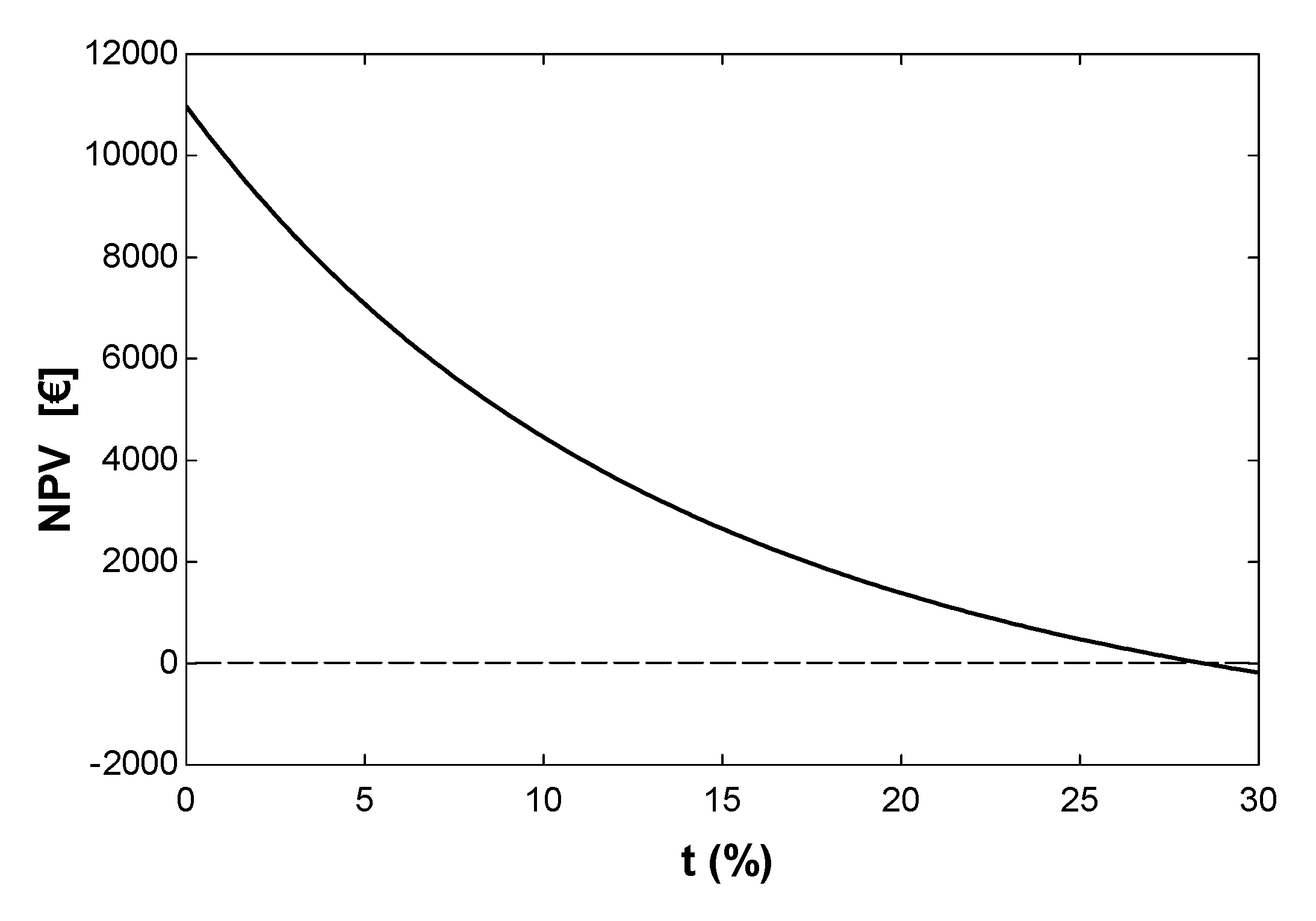
It is worth mentioning the influence of certain parameters on the results. Firstly, it should be reiterated that a discount rate of 12% was chosen. This parameter reflects a combination of a risk-free rate, such as the return on Treasury bills, and a risk premium. Together, these represent the minimum acceptable return for an investor. However, this 12% rate is not a universally agreed standard. Given the importance of the discount rate in economic evaluations, a sensitivity analysis was conducted to assess its impact. Figure 4 shows how the NPV fluctuates across a range of discount rates from 0% to 30%. As expected, the NPV declines as the discount rate rises. In this scenario, the NPV reaches zero at the previously calculated discount rate of 27.81%. This indicates that any rate above this threshold would make the investment economically unfeasible.
Other interesting parameters to analyze are maintenance costs, both with and without implementation of the IEC 62034:2012 standard. A sensitivity analysis was performed using maintenance costs with and without the implementation of the IEC 62034:2012 standard, with the following ranges.
-
Costs with the implementation of the IEC 62034:2012 standard: 1000–5000 EUR/year.
-
Costs without the implementation of the IEC 62034:2012 standard: 0–1000 EUR/year.
The results are shown in Figure 5. As can be seen in the graph, the economic viability of the IEC 62034:2012 standard effectively depends on the relative maintenance costs. The NPV would only become negative, and the investment would not be justified if the costs without IEC implementation were extremely low and those with IEC implementation were extremely high.
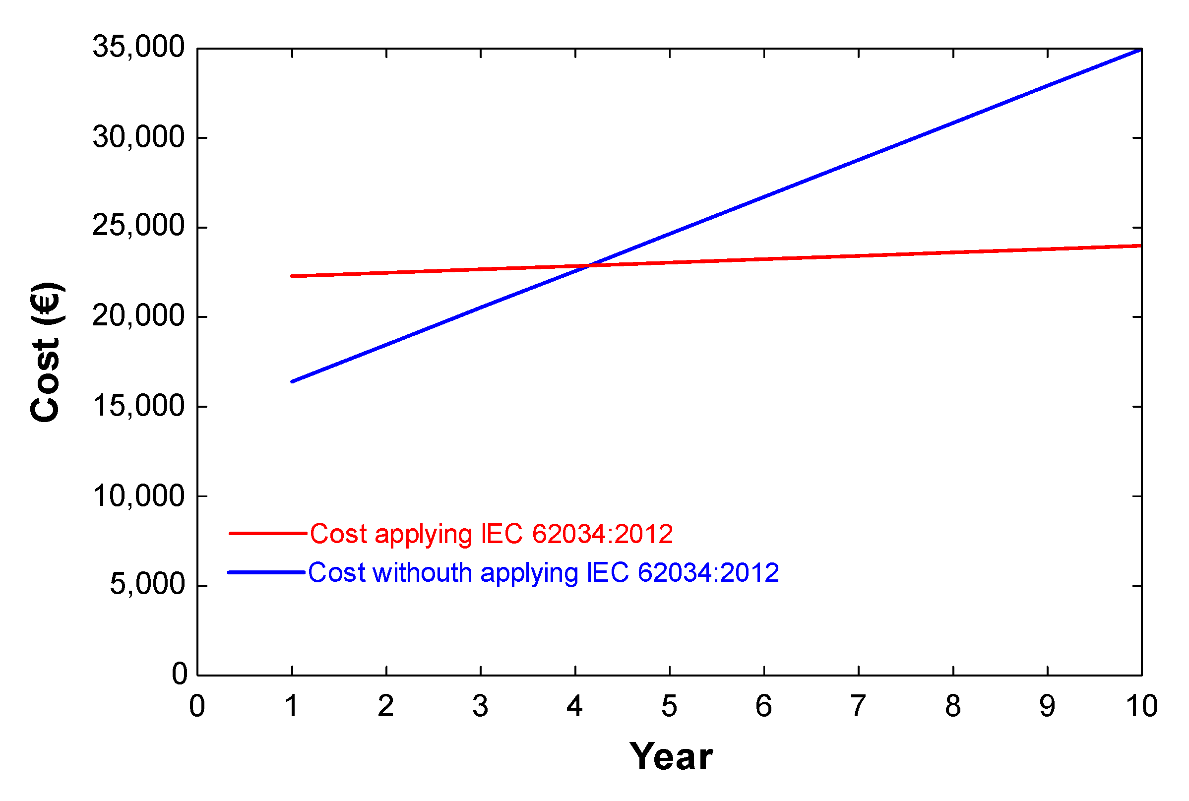
Another interesting aspect is that autonomous emergency lighting systems with manual preventive maintenance present a lower initial investment. However, over a 10-year period, their total cost is significantly higher, as evidenced in Figure 6, which is based on the previously presented financial analysis.
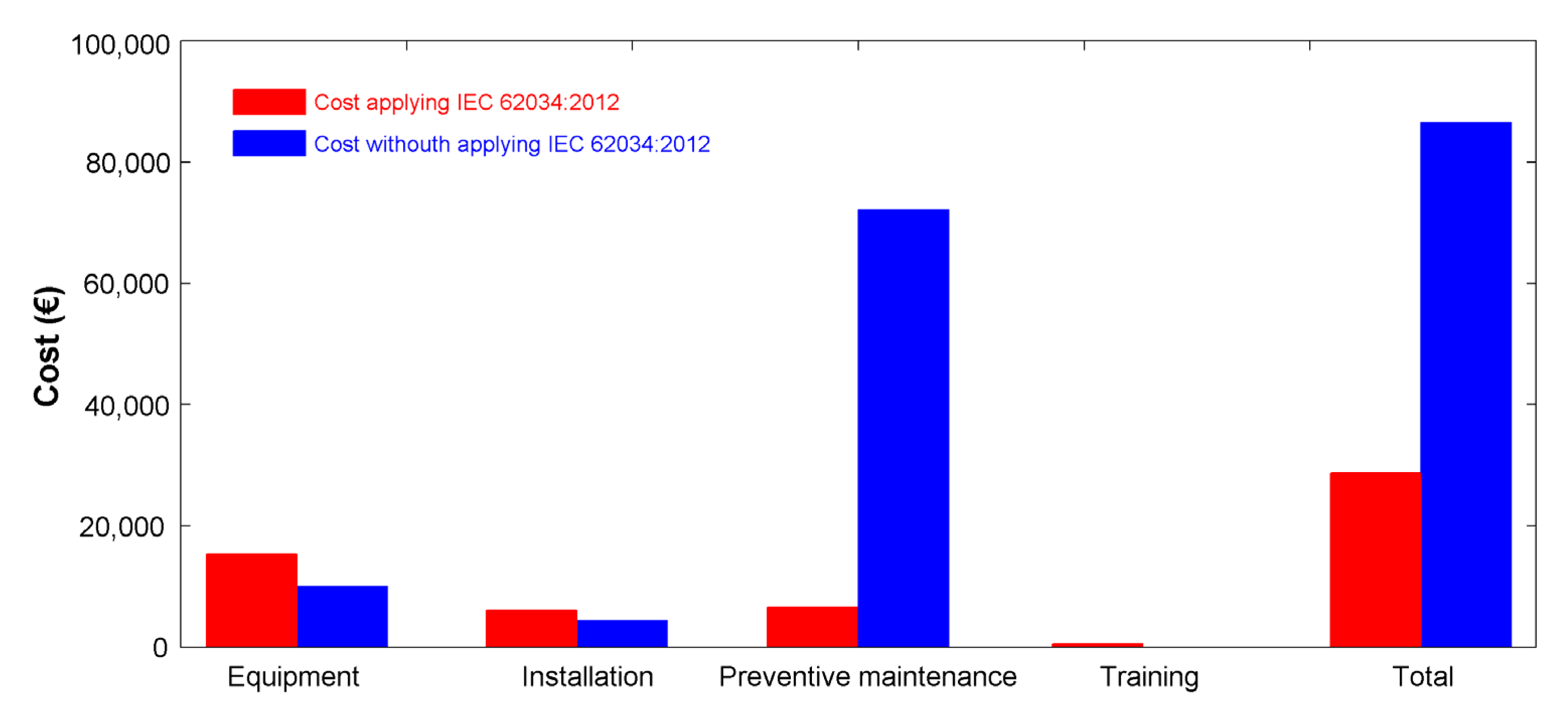
This cost differential is attributable to the recurring annual expense associated with preventive maintenance, which necessitates the manual inspection of the luminaires. To provide greater clarity, Figure 7 illustrates the proportional impact of the previously identified cost components over the vessel’s estimated service life of 35 years.
In other words, when evaluating the cost on a per-luminaire basis, it may be concluded that, over a 25-year period, the total system cost—including the initial investment and preventive maintenance—would amount to 1966 EUR per luminaire under a manual maintenance scheme. In contrast, implementing an automated prevention system would reduce the cost to 652 EUR per luminaire. This yields a cost ratio of approximately 3:1 in favor of the automated solution.
With regard to the extrapolation of results, the implementation of this type of system is mandatory in the following cases:
  • Vessels in which the emergency source of power is not automatically connected to the emergency switchboard within 45 s;
  • Vessels assigned the class notations Passenger Ship or Ferry.
Accordingly, any vessel not equipped with a fast-start emergency generator and certainly, in any ferries, Ro-Pax vessels, cruise ships, ocean liners, offshore platforms, and, in general, any ship certified to carry more than 12 passengers, is required by regulation to be fitted with an escape lighting system. As a result, there exists a substantial number of vessels for which the deployment of such systems is both applicable and necessary.
Regarding the potential implementation on other merchant vessels, this system could be applied—under the same assumptions and conclusions previously outlined—to any ship in which the emergency lighting is not continuously lighted up. In such scenarios, the system would serve the dual function of emergency and escape lighting. While the applicability may be more limited on vessels where either the normal or emergency lighting remains continuously energized, the system could nonetheless be implemented to enhance automated monitoring and control capabilities.
This system is also suitable for retrofit installation on existing vessels or offshore platforms. The primary challenges associated with such implementation include the integration of the DALI bus, the replacement of the existing driver with a DALI-compatible driver, and the limited number of cable glands available on typical luminaires (generally no more than two). When utilizing the existing cabling infrastructure, it will be necessary to route additional wiring to a nearby junction box, where the new controller DALI driver or a gateway can be installed to ensure DALI bus continuity. In cases where new cabling is deployed, it should be specified to include the five conductors required for full system functionality.

5. Conclusions

The present work analyzes the implementation of the IEC 62034:2012 standard (automatic test system for battery-powered emergency evacuation lighting) in an MPV vessel. As some of the crew on these vessels are scientists, escape lighting is recommended for safety and security reasons. Implementing the IEC 62034:2012 standard for automatic test systems governing battery-powered emergency escape lighting considerably enhances the safety and operational efficiency of multipurpose vessels. Real-time monitoring and management of escape lighting systems, enabled by this standard, ensures reliability during critical events and significantly enhances safety for crew and passengers. Moreover, the shift from manual to automated testing not only leads to reduced maintenance costs but also guarantees that the escape lighting remains in optimal working condition, which is crucial during emergencies. The techno-economic analysis conducted demonstrates a favorable return on investment, further advocating for the integration of these standards in both new and existing maritime vessels.
Looking ahead, the methodologies and insights gained from this study have a broader application than just the vessel analyzed, making them relevant to various types of maritime operations that require effective escape lighting systems. Future research should focus on evaluating the long-term impact of implementing the IEC 62034:2012 standard across diverse marine environments, as well as investigating the integration of innovative technologies, such as intelligent lighting controls and renewable energy sources. This proactive approach will enhance both safety and sustainability in maritime operations. Ultimately, effectively adopting the IEC 62034:2012 standard is a significant step forward in maritime safety and highlights the need for ongoing investment in safety technologies within the shipping industry.

Author Contributions

Conceptualization, L.G.R. and M.I.L.G.; methodology, L.C.-S.; software, L.G.R., formal analysis, L.G.R., M.I.L.G. and L.C.-S.; investigation, L.G.R., M.I.L.G. and L.C.-S.; resources, L.C.-S. and L.G.R.; writing—original draft preparation, L.G.R. and M.I.L.G.; writing—review and editing, M.I.L.G. and L.C.-S.; visualization, L.C.-S.; supervision, L.C.-S. All authors have read and agreed to the published version of the manuscript.

Funding

This research was partially funded by Project 101181231, “Multi-disciplinary risk management for stable, safe, and sustainable offshore wind-powered hydrogen production” (WINDHY), financed by the European Commission under the Marie Skłodowska-Curie (MSCA) Staff Exchanges Actions of the Horizon Europe. This research was also partially funded by Project TED2021-132534B–I00, funded by MICIU/AEI/10.13039/501100011033, and by the “European Union NextGenerationEU/PRTR”. This study contributes to the international project 3E-Partnership (proposal number 101128576), funded with support from the European Commission under the Action ERASMUS-LS and the Topic ERASMUS-EDU-2023-CBHE-STRAND-2.

Institutional Review Board Statement

Not applicable.

Informed Consent Statement

Not applicable.

Data Availability Statement

The original contributions presented in the study are included in the article, further inquiries can be directed to the corresponding author.

Conflicts of Interest

The authors declare no conflicts of interest.

References

  1. DNV GL. Rules for Classification: Ships—Part 4: Systems and Components, Chapter 8: Electrical Installations; Edition January 2017; DNV GL: Høvik, Norway, 2017. [Google Scholar]
  2. Jelena, A. Emergency escape lighting systems. In Proceedings of the 1st International Conference on Electrical and Control Technologies, ECT, Kaunas, Lithuania, 4–5 May 2006. [Google Scholar]
  3. Aizlewood, C.E.; Webber, G.M.B. Escape route lighting: Comparison of human performance with traditional lighting and wayfinding systems. Light. Res. Technol. 1995, 27, 133–143. [Google Scholar] [CrossRef]
  4. Towle, L.C. An analysis of the overall integrity of an escape route lighting system. In Proceedings of the 5th International Conference on Electrical Safety in Hazardous Environments, London, UK, 19–21 April 1994. [Google Scholar] [CrossRef]
  5. Zhang, Q.; Zhou, J.; Liu, J. Design of a ship light environment control system. In Proceedings of the 3rd International Conference on Artificial Intelligence, Automation, and High-Performance Computing (AIAHPC 2023), Qingdao, China, 28–30 July 2023; Volume 12717. [Google Scholar] [CrossRef]
  6. Li, W.; Wang, Y.; Ye, Z.; Liu, Y.A.; Wang, L. Development of a mixed reality assisted escape system for underground mine-based on the mine water-inrush accident background. Tunn. Undergr. Space Technol. 2024, 143, 105471. [Google Scholar] [CrossRef]
  7. International Maritime Organization. International Convention for the Safety of Life at Sea (SOLAS); IMO Publishing: London, UK, 2020. [Google Scholar]
  8. American Bureau of Shipping. Guidance Notes on the Application of Escape Lighting Systems; ABS Publications: Houston, TX, USA, 2021. [Google Scholar]
  9. European Maritime Safety Agency. Guidelines for the Installation of Emergency Lighting on Ships; EMSA: Lisbon, Portugal, 2019. [Google Scholar]
  10. Fuchtenhans, M.; Grosse, E.; Glock, C. Literature review on smart lighting systems and their application in industrial settings. In Proceedings of the 6th International Conference on Control, Decision and Indormation, Paris, France, 23–26 April 2019. [Google Scholar] [CrossRef]
  11. IEC 62034:2012; Automatic Test Systems for Battery Powered Emergency Escape Lighting. International Electrotechnical Commission: Geneva, Switzerland, 2012.
  12. Gritsuk, I.; Nosov, P.; Dyagileva, O.; Masonkova, M. Improving safety of navigation by constructing a dynamic model of the navigator’s actions in the conditions of navigation risks. Transp. Syst. Technol. 2023, 41, 84–95. [Google Scholar] [CrossRef]
  13. Shibabrata, M.; Parthassarathi, S.; Saswti, M. Development of a microcontroller based emergency lighting system with smoke detection and mobile communication facilities. Light Eng. 2019, 27, 46–50. [Google Scholar] [CrossRef]
  14. Andrzej, P. Comparison of results of computer simulations for the escape route lighting installation. Prz. Elektrotechniczny 2016, 92, 169–177. [Google Scholar]
  15. Sędziwy, A.; Basiura, A.; Wojnicki, I. Roadway Lighting Retrofit: Environmental and Economic Impact of Greenhouse Gases Footprint Reduction. Sustainability 2018, 10, 3925. [Google Scholar] [CrossRef]
  16. Salata, F.; Golasi, I.; Bombelli, E.; Vollaro, E.; Nardecchia, F.; Pagliaro, F.; Gugliermetti, F.; Vollaro, A. Case study on economic return on investments for safety and emergency lighting in road tunnels. Sustainability 2015, 7, 9809–9822. [Google Scholar] [CrossRef]
  17. Wati, G.; Suardi, S.; Mubarak, A.A. Analysis of Generator Power Requirements for Lighting Distribution Using LED Lights on a 500 DWT Sabuk Nusantara. Indones. J. Marit. Technol. 2023, 1, 45–51. [Google Scholar] [CrossRef]
  18. Suardi, S.; Kyaw, A.Y.; Wulandary, A.I. Impacts of Application Light-Emitting Diode (LED) Lamps in Reducing Generator Power on Ro-Ro Passenger Ship 300 GT KMP Bambit. JMES Int. J. Mech. Eng. Sci. 2023, 7, 44–53. [Google Scholar] [CrossRef]
  19. DNV. Rules for Classification. Ships. Part 4: Systems and Components. Chapter 8: Electrical Installations. 6.2, Lighting; DNV GL: Høvik, Norway, 2021. [Google Scholar]
  20. Mukazi, I.; Wijaya, M.M.; Dewadi, F.M. Development of Solar-Powered Fishing Boats with Leak Threat Sensor System: A Sustainable Solution for Indonesian Fishermen. Kumawula 2024, 7, 497–506. [Google Scholar] [CrossRef]
  21. Yao, J.; Ren, J.; Zhong, Z. Design of monitoring and control system for unmanned ship based on FPGA. In Proceedings of the Second International Conference on Digital Society and Intelligent Systems (DSInS 2022), Chengdu, China, 2–4 December 2023; Volume 12599. [Google Scholar]
  22. Talluri, L.; Nalianda, D.; Kyprianidis, K. Techno economic and environmental assessment of wind assisted marine propulsion systems. Ocean Eng. 2016, 131, 301–322. [Google Scholar] [CrossRef]
  23. Lin, A.J.; Chang, H.Y.; Hung, B. Identifying Key Financial, Environmental, Social, Governance (ESG), Bond, and COVID-19 Factors Affecting Global Shipping Companies—A Hybrid Multiple-Criteria Decision-Making Method. Sustainability 2022, 14, 5148. [Google Scholar] [CrossRef]
  24. Wang, Y.J.; Lee, H.S. Evaluating financial performance of Taiwan container shipping companies by strength and weakness indices. Int. J. Comput. Math. 2010, 87, 38–52. [Google Scholar] [CrossRef]
  25. Christodoulou, A.; Dalaklis, D.; Ölçer, A. Inclusion of Shipping in the EU-ETS: Assessing the Direct Costs for the Maritime Sector Using the MRV Data. Energies 2021, 14, 3915. [Google Scholar] [CrossRef]
  26. Jin, H.; Schinas, O. Ownership of assets in Chinese shipping funds. Int. J. Financ. Stud. 2019, 7, 69. [Google Scholar] [CrossRef]
  27. Lin, A.J.; Sun-Weng, H.; Chang, H.Y. Factors influencing follow-on public offering of shipping companies from investor perspective—A hybrid multiple-criteria decision-making approach. Technol. Econ. Dev. Econ. 2024, 30, 1087–1119. [Google Scholar] [CrossRef]
  28. IEC 62386-101:2022; Digital Addressable Lighting Interface—Part 101: General Requirements—System Components. International Electrotechnical Commission: Geneva, Switzerland, 2022.
  29. ISO 9885-3_2006; Lighting of Work Places, Part 1: Indoor. ISO: Geneva, Switzerland, 2006.
  30. Available online: https://generadordeprecios.info/obra_nueva/Instalaciones/Electricas/Cables/IEH010_Cable_electrico_de_450_750_V_de_ten_0_0_1_0_0_0_0_0_0_0_0_0_0_0.html (accessed on 20 May 2025).
  31. Available online: https://www.erieri.com/salary/job/marine-surveyor/germany (accessed on 20 May 2025).
  32. Available online: https://www.erieri.com/salary/job/marine-surveyor/spain (accessed on 20 May 2025).
  33. Available online: https://www.erieri.com/salary/job/marine-surveyor/united-states (accessed on 20 May 2025).
  34. Available online: https://generadordeprecios.info/ (accessed on 20 May 2025).
Figure 1. Main networks of the MPV vessel analyzed in the present work.
Eng 06 00110 g001
Figure 2. Lighting calculations in the engine room.
Eng 06 00110 g002
Figure 3. NPV against the useful life.
Eng 06 00110 g003
Figure 4. Variation of NPV with respect to the discount rate.
Eng 06 00110 g004
Figure 5. Variation of NPV with respect to the maintenance costs with and without implementation of IEC 62034:2012 standard.
Eng 06 00110 g005
Figure 6. Total cost of manual test system and IEC 62034:2012 system.
Eng 06 00110 g006
Figure 7. Total cost by item during the service life of the vessel.
Eng 06 00110 g007
Table 1. Main dimensions of the MPV analyzed in the present work.
Length Overall52.8 m
Length between perpendiculars48.0 m
Beam14.0 m
Depth to tween deck5.2 m
Depth to main deck7.9 m
Depth to 1st deck10.7 m
Depth to 2nd deck13.3 m
Speed13 kn
Accommodation26 (12 crew + 14 scientists)
Table 2. Lighting levels.
AreaLight Level Intensity (lux)
Engine control room300 (minimum 200)
Lockers100
Gallery, pantry300
Corridor, stairs100 (minimum 50)
Engine rooms200
Cabins200 (minimum 100)
Dayrooms300
Wheelhouse200
Bathrooms and toilets150
Table 3. Number of luminaires in each room in the ship’s networks.
QtyDescriptionNet
148TL Vario M, LED, 2200 lm, 230/0/50/60, IP66/67, M8 bolt, 2 × M20 PAMain and Emerg.
6TL Vario M, LED, 2200 lm, 230/0/50/60, IP66/67, M8 bolt, 2 × M20 PA, battery backup 3 hEscape
32TL53S Technical luminaire, LED, max.1 × 10 W/1.200 Lm/230/50/60Main and Emerg.
6ST76S Floodlight, LED, 1 × 25 W, 115/230 V0/50/60 Hz, 22°Main and Emerg.
15ST76 L Floodlight, LED, 3 × 25 W, 115/230 V0/50/60 Hz, 52°Main and Emerg.
28TL09 Watertight Luminaire, LED, 1 × 4 W/230 V/50/60 Hz, galvanized steel housing, 3 h Battery backupEscape
10HL71 BU Sign Light, 1 W/230/50/60, IP20, 3 h battery backupEscape
134DL120 Downlight, LED, max. 1 × 18 W/230/50/60, RAL9016 clear glass lensMain and Emerg.
28DL120 Downlight, LED, max. 1 × 18 W/230/50/60, RAL9016 clear glass lens, DIMMain and Emerg.
8DL120 Downlight, LED, max. 1 × 18 W/230/50/60, RAL9016 red glass lensMain and Emerg.
32DL04 Downlight, LED, max.1 × 5 W/500 mA, chrome incl. Driver unit, 500 mA, WagoMain and Emerg.
23SP66 M Mirror luminaire LED max. 1 × 9 W/1.100 lm/830/230 V, trafo/shaver socket/switchMain
45TI14 Charttable Light, LED, max. 1 × 3 W/230/12 V/50/60 HzMain
8TI14 Charttable Light, LED, max. 1 × 3 W/230/12 V/50/60 Hz dimmable incl. LED driver, LCBI 15 W 350 mA, dimMain and Emerg.
18WL30 Q Wall-/reading light, LED, max. 1 × 1 W/110–240 V/50/60 HzMain
28WL282 Wall-/Bedlight, LED, max. 1 × 6 W/230 V/0/50/60 Hz, switch leftMain
22WL100 Q Wall-/reading light, LED, max. 1 × 1 W/120–240 V/50/60 HzMain
32KL/KR61 ZS Kitchen and coldroom luminaire, LED, max. 20 W/230 V/50/60 HzMain and Emerg.
4EX40 S Explosionproof luminaire, LED 22 W, 2100 lm/120–230 V/50/60 Hz, IP67, stainless steel housing, 2 M20 plastic cable glands, LP160 bracketsMain and Emerg.
Table 4. Main, emergency, and escape lighting power.
QtyDescriptionUnitary Power (W)Main Lighting Power (W)Emergency Lighting Power (W)Escape Lighting Power (W)
148TL Vario M, LED, 2200 lm, 230/0/50/60, IP66/67, M8 bolt, 2 × M20 PA2019809800
6TL Vario M, LED, 2200 lm, 230/0/50/60, IP66/67, M8 bolt, 2 × M20 PA, battery backup 3 h2000120
32TL53 S Technical luminaire, LED, max. 1 × 10 W/1.200 Lm/230/50/609189990
6ST76 S Floodlight, LED, 1 × 25 W, 115/230 V0/50/60 Hz, 22°2080400
15ST76 L Floodlight, LED, 3 × 25 W, 115/230 V0/50/60 Hz, 52°757503750
28TL09 Watertight Luminaire, LED, 1 × 4 W/230 V/50/60 Hz, galvanized steel housing, 3 h Battery backup400112
10HL71 BU Sign Light, 1 W/230/50/60, IP20, 3 h battery backup20020
134DL120 Downlight, LED, max. 1 × 18 W/230/50/60, RAL9016 clear glass lens1816028100
28DL120 Downlight, LED, max. 1 × 18 W/230/50/60, RAL9016 clear glass lens, DIM183421620
8DL120 Downlight, LED, max. 1 × 18 W/230/50/60, RAL9016 red glass lens1890540
32DL04 Downlight, LED, max. 1 × 5 W/500 mA, chrome incl. Driver unit, 500 mA, Wago5105550
23SP66 M Mirror luminaire LED max. 1 × 9 W/1.100 lm/830/230 V, trafo/shaver socket/switch1023000
45TI14 Charttable Light, LED, max. 1 × 3 W/230/12 V/50/60 Hz313500
8TI14 Charttable Light, LED, max. 1 × 3 W/230/12 V/50/60 Hz dimmable incl. LED driver, LCBI 15 W 350 mA, dim31590
18WL30 Q Wall-/reading light, LED, max. 1 × 1 W/110–240 V/50/60 Hz11800
28WL282 Wall-/Bedlight, LED, max. 1 × 6 W/230 V/0/50/60 Hz, switch left1130800
22WL100 Q Wall-/reading light, LED, max. 1 × 1 W/120–240 V/50/60 Hz12200
32KL/KR61 ZS Kitchen and coldroom luminaire, LED, max. 20 W/230 V/50/60 Hz204202200
4EX40 S Explosionproof luminaire, LED 22 W, 2100 lm/120–230 V/50/60 Hz, IP67, stainless steel housing, 2 M20 plastic cable glands, LP160 brackets2266220
Table 6. Increase in the initial investment.
DescriptionTotal Inversion (EUR)
Modification of the luminaire1204.28
Wiring modification1771
DALI controller3146
Programming hours1050
Training600
Total7771
Table 7. Breakdown of investment year by year over the useful life.
Year (i)Saving (EUR)Cash Flow (EUR)Cash Flow/(1 + t)i (EUR)
11875−6083.5−5264.29
2187518751494.74
3187518751334.59
4187518751191.60
5187518751063.93
618751875949.93
718751875848.15
818751875757.28
918751875676.14
1018751875603.70
NPV (EUR)3655.78
Disclaimer/Publisher’s Note: The statements, opinions and data contained in all publications are solely those of the individual author(s) and contributor(s) and not of MDPI and/or the editor(s). MDPI and/or the editor(s) disclaim responsibility for any injury to people or property resulting from any ideas, methods, instructions or products referred to in the content.

