3.3. Pick-and-Place Challenge
One of the primary goals of this paper is to use Arduino-MEGA to both manually and automatically operate the robotic arm to pick up moving objects. In industries, highly modern robots are utilized, but the controlling is still performed by manual control (Joy-Stick), processors like Arduino and microprocessors, and programmable-logic-control (PLC) [
7]. Using these processors has a number of drawbacks, such as the inability of microcontrollers to function in situations with strong vibration, humidity, corrosion, and other environmental conditions. The PLC, which controls the robotic arm like a brain, solves all of these issues [
23,
26,
27]. Despite all these advantages of using PLC as the main controller for robots, in this work, the economic capabilities to provide it as an advanced controller are not available. The goal of this paper is also to develop and construct a more affordable, practical, and small robotic arm that can carry out a variety of tasks that humans have been shown to be too risk-prone to perform.
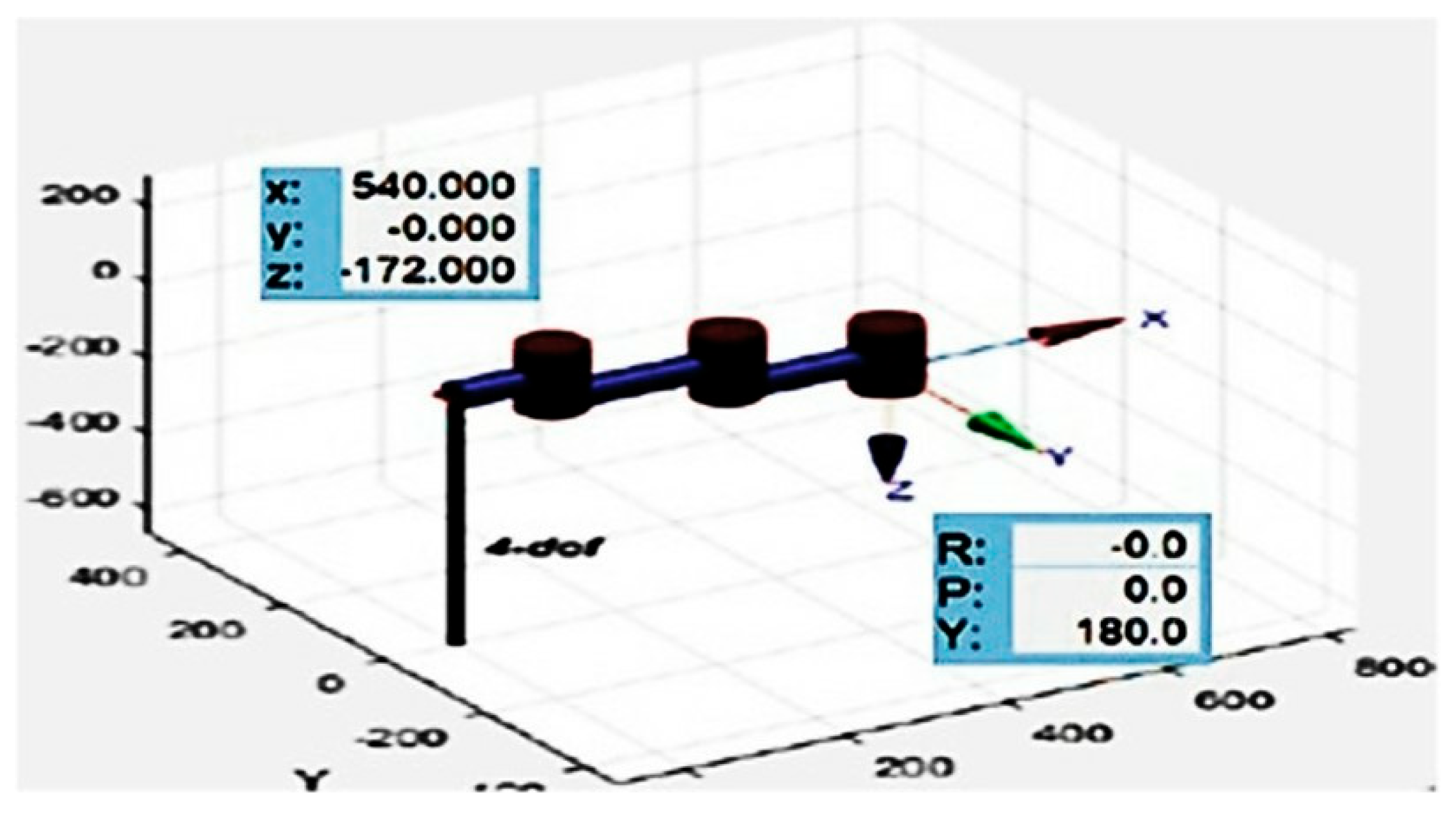
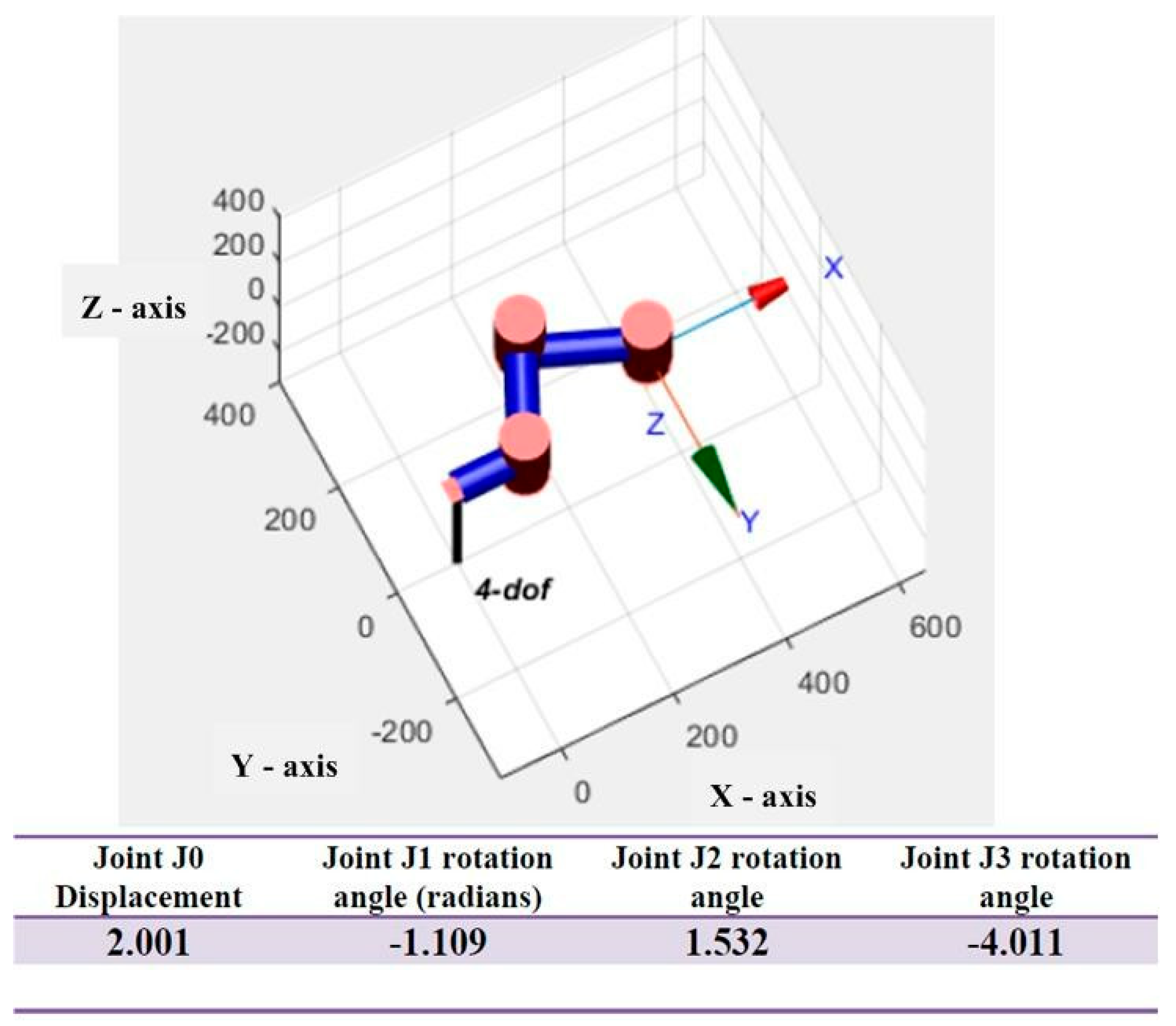
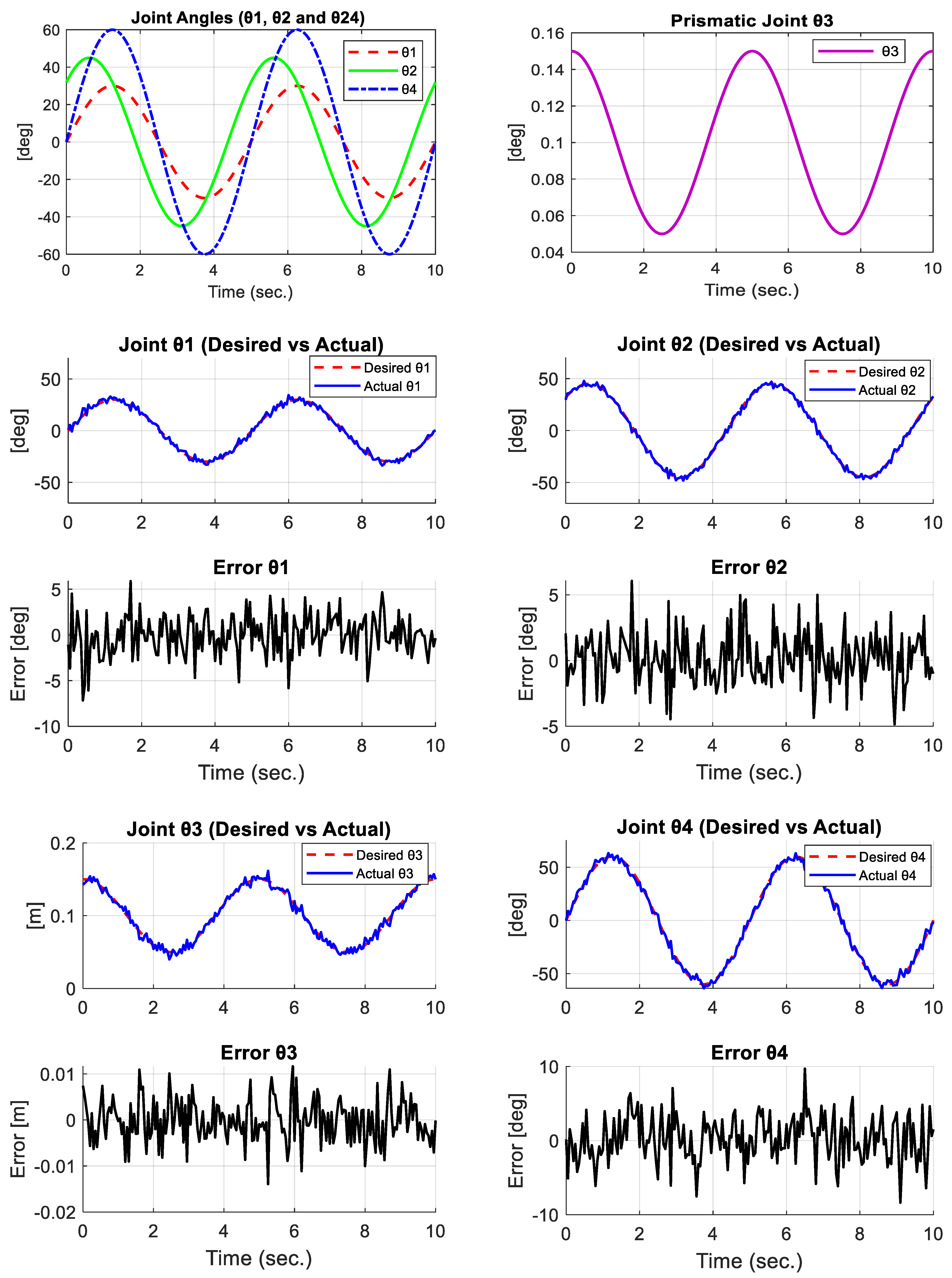
Figure 9 displays the time-domain trajectories for each joint as well as the tracking errors between the desired and actual responses from the simulation of the 4-DOF SCARA manipulator. As anticipated from the preset input profiles, the findings showed that the trajectories for the rotational joints
and
followed the sinusoidal-references. The observed differences between the intended and actual trajectories support the model’s guesses and shed light on how subtle the kinematic chain is to changes in joint motion. In contrast to the rotational joints, the prismatic joint
demonstrated consistent tracking performance with comparatively minor variations [
6]. Its linear motion, which is less vulnerable to compound kinematic effects, is the cause of this behavior. When it came to the end-effector-joint
(gripper-rotation), the trajectory was generally in line with the reference, but there were some notable differences at particular points in time, which demonstrated how upstream joint variances affect the terminal orientation. The tracking performance across all joints was quantified by the Root-Mean-Square-Error (RMSE) [
21] analysis.
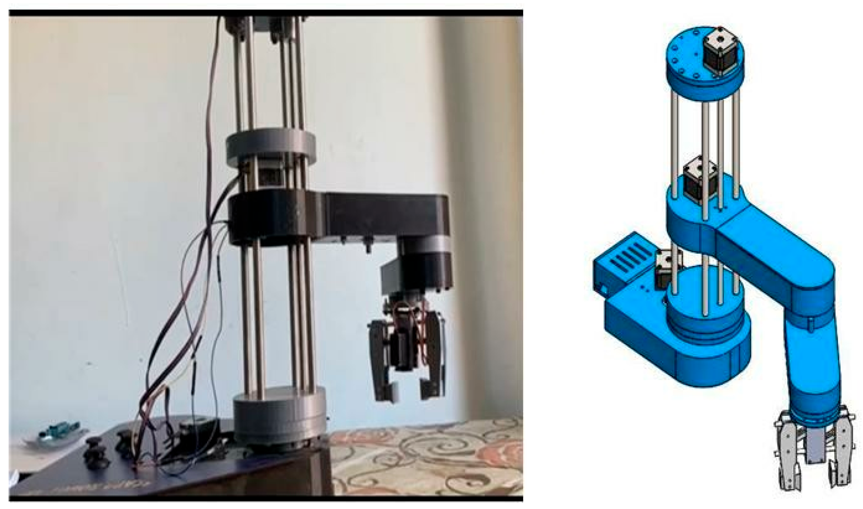
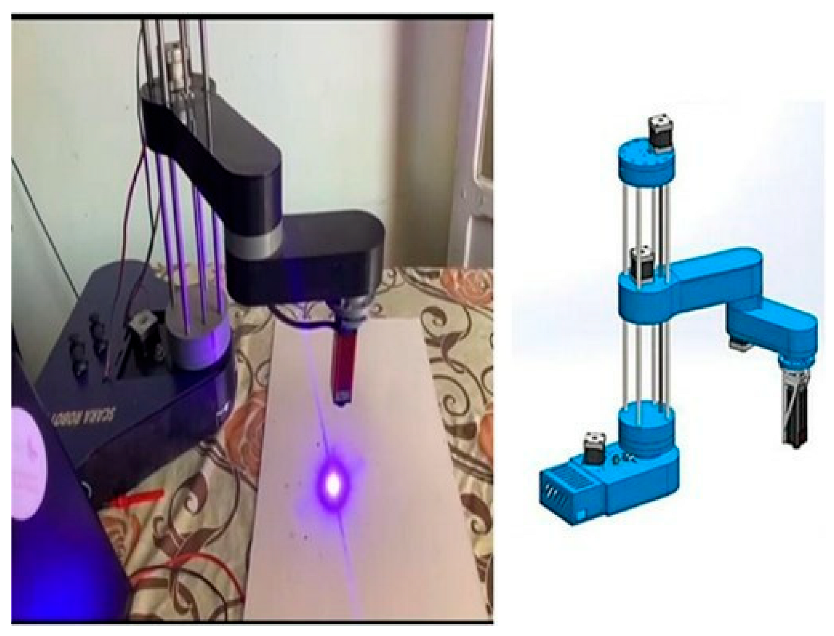
A basic gripper that is powered by a servo-motor (MG996R) has been built. The two sides of the gripper slip were placed onto two 6 mm rods. A servo horn, a few 3D-printed links, and M3-bolts and nuts are used to attach the two sliding sides to the servo. The entire gripper using M3-bolts and nuts has been assembled. Assembling some of these components requires nerves because the area for fastening the bolts and nuts is rather small. However, this design has an advantage where changing the gripper-ends is simple. They can have a certain shape or be wider or thinner. The full algorithmic description, mathematical formulations, and performance evaluation of this intelligent PAPO framework are detailed in the following section.
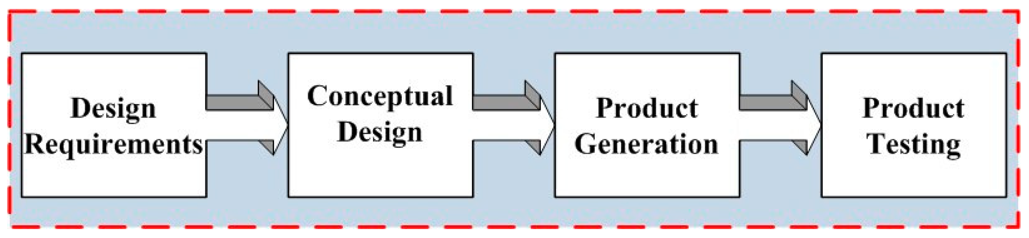
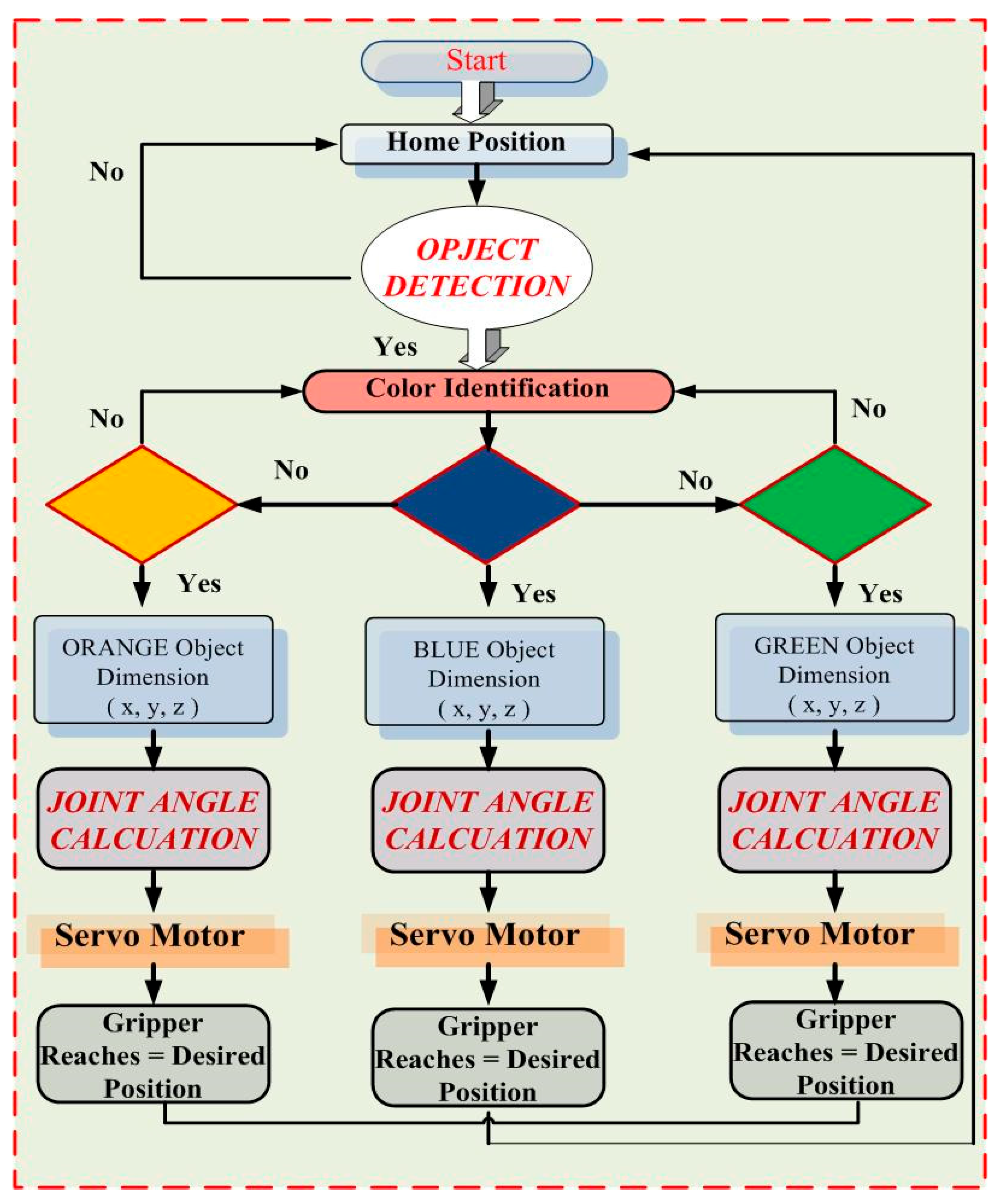
The flowchart presented in
Figure 10 illustrates the conventional sequence of the PAPO implemented by the developed 4-DOF SCARA robot. This process relies mainly on rule-based control logic executed through microcontroller commands to achieve motion synchronization, gripper-actuation, and positional-tracking. This method guarantees a consistent and repeatable workflow, but it is not flexible enough to handle dynamic changes in the mass, position, or type of objects that the robot may meet.
3.4. Intelligent Pick-and-Place Optimization Using Machine Learning
To further enhance the accuracy, adaptability, and decision making capabilities of the proposed SCARA robot during PAPOs, two supervised ML algorithms were integrated and tested. This section presents a comprehensive ML framework developed to enhance the positioning accuracy, success rate, and cycle time consistency of the designed 4-DOF SCARA robot. Two models were implemented:
Both models were fully integrated into the real-time control architecture and validated experimentally over 360 PAPOs, under three speed profiles (slow, medium, fast), three object types, and three payload conditions (100 g, 200 g, 300 g). Approximately 14,400 raw sensor readings were collected via encoder feedback (200 Hz), gripper force sensor (40 Hz), motor current estimation, and vision module (25 Hz). After preprocessing and temporal aggregation, each cycle was represented as a 19-dimensional feature vector, encompassing kinematic, temporal, dynamic, and vision-based descriptors.
The dataset was partitioned into training, validation, and test sets, comprising 70% (252 samples), 15% (54 samples), and 15% (54 samples) of the data, respectively, while a 5-fold cross-validation procedure was employed for hyperparameter optimization.
Table 4 shows that each cycle has been converted into a single sample using pooled statistics.
All continuous features were normalized using z-score normalization [
9,
25]:
where statistics (µ, σ) were only computed from the training set to prevent data leakage.
The feature engineering process was structured into four sequential stages: signal filtering, temporal aggregation, conversion to robot-centric variables, and encoding of categorical object attributes. Joint angle and velocity measurements were smoothed using a second-order low-pass Butterworth filter with an 8 Hz cutoff to reduce high-frequency noise. Gripper force signals were processed using a moving average filter over five samples, while camera-based color and shape measurements were refined through median filtering to ensure consistency. For each sensor-derived feature f(t), cycle-level statistical descriptors—including mean, maximum, minimum, and standard deviation—were computed to summarize the temporal behavior. Representative features extracted through this pipeline included grip force (std.), motor current (max), motor current (mean), , and .
Filtering ensures that the ML models receive stable and drift-free trajectories, improving classification and regression accuracy. Each PAPO generates between 40 and 200 raw samples. Rather than using the full time-series (which requires deep models like LSTMs), the data are converted into cycle-level statistical descriptors consistent with low-cost SCARA robots. This dimensionality reduction makes the dataset suitable for classical ML (SVM, RF) while preserving the key information.
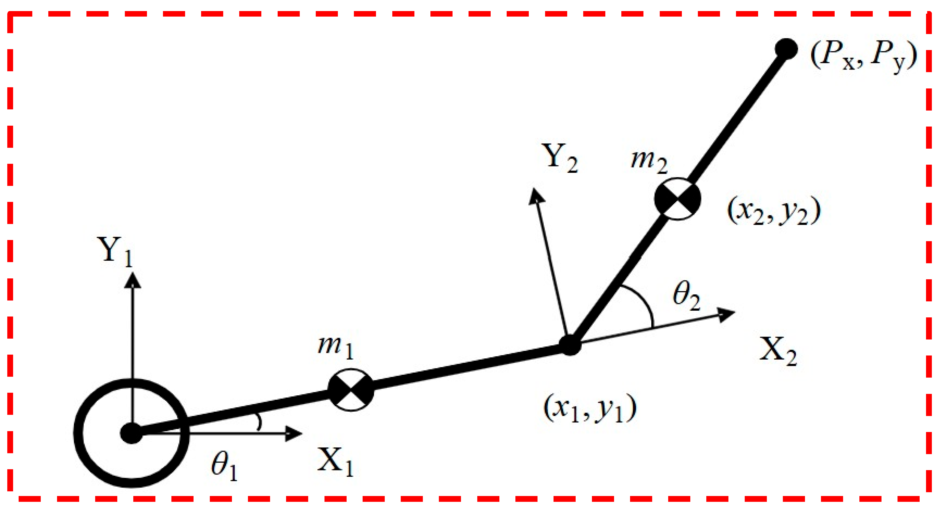
The following kinematic features were computed using the forward kinematics model described earlier:
The extracted features comprised both the desired end-effector pose and the corresponding actual pose . The pose deviation is . These features reflect the mechanical behavior of the actual robot and directly influence the SVM and RF predictions. Dynamic features captured the load conditions and execution-speed, including mean gripper-force, mean motor current, estimated payload, and a velocity profile code (0 = slow, 1 = medium, 2 = fast). These descriptors are critical for predicting positional errors and cycle times. Additionally, categorical object attributes, such as color (one-hot encoded: R, G, B) and shape (one-hot encoded: Cube, Pyramid, Rectangular prism), enable the ML models to adjust motion parameters, including speed and grip force, according to the object features.
The SVM classifier was trained to predict a binary success label, defined as
The RF regressor was used for continuous predictions, including the positional error:
The cycle time was measured from the start to the end of the movement. All continuous features were normalized using standardized score normalization. Categorical object attributes were encoded using standard one-hot encoding. The final 19-dimensional feature vector for each cycle is
This feature vector is fully measurable on the robot and directly corresponds to the 360 experimental cycles.
The SVM classifier evaluates whether the grasping condition is feasible under the current parameters, while the RF model predicts the expected positional error and completion time. Based on these predictions, the controller dynamically adjusts motion trajectories and gripping parameters before executing the cycle, resulting in improved accuracy and overall efficiency. In addition to improving the robot’s capacity to make decisions, this feature lays the groundwork for future industrial applications that require autonomous and adaptive functioning. The full algorithmic description, mathematical formulations, and performance evaluation of this intelligent PAPO framework are detailed in the following sections.
3.4.1. SVM-Based Classification
The SVM classifier is used to predict the success probability of each PAPO based on the engineered 19-dimensional feature vector. Its output enables the SCARA robot to pre-evaluate whether a grasping attempt is likely to fail and adjust the trajectory or grip force before execution. It is given a training dataset , where
The SVM classifier is formulated through the following primal optimization problem [
24,
28]:
Subject to
where
is the penalty misclassified samples,
is weight-vector, and
is the nonlinear kernel mapping. The SVM decision function is expressed as
Preliminary investigations indicated that the Radial Basis Function (RBF) kernel delivers improved generalization performance—particularly suitable for structured, low-dimensional datasets [
29]:
This choice is justified because of the following:
It captures nonlinear relationships among kinematic and dynamic variables;
It manages overlapping classes in near-boundary cases;
It remains robust to noise originating from force-sensors and stepper-motors.
A 5-fold cross-validation grid search was undertaken on the 252-sample training set. The best-performing setup is reported in
Table 5.
Thus, the final SVM model was configured using an RBF kernel with C = 10, γ = 0.1, and balanced class-weighting.
The trained SVM produces two outputs: a binary success label (success flag ∈ {0,1}) and a calibrated success probability estimated using Platt scaling.
where
is the raw SVM decision score.
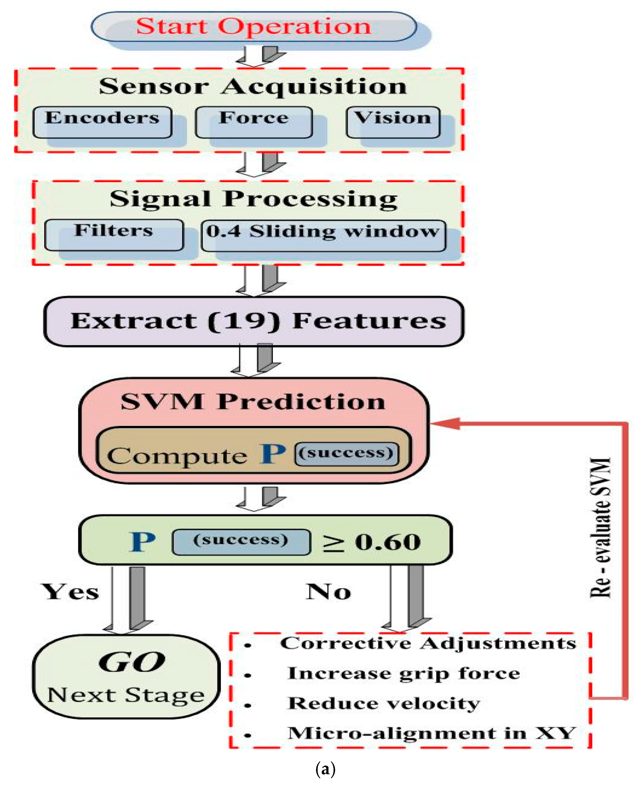
This probability is used by the decision module (
Figure 11b) to activate fallback strategies when
. The SVM model was evaluated on a 54-sample test set as shown in
Table 6.
The performance metrics can be summarized as follows:
The majority of misclassifications happened with higher payloads and fast-motion settings, when dynamic oscillations impacted pose stability. Overall, the SVM provides a rapid and reliable prediction mechanism for early failure detection, and its probability output is then exploited by the RF-based rectification module.
3.4.2. Random Forest Regression
The RF model is used to predict two continuous quantities essential for evaluating the robot’s performance:
RF was selected, owing to its tolerance to noise, capacity to represent nonlinear interactions, and high-interpretability, which is particularly ideal for low-cost SCARA robots where dynamic fluctuations (backlash, friction, lightweight structural compliance) greatly affect accuracy.
The RF consists of an ensemble of decision trees [
30]:
where
represents the prediction of tree (t) and (x) = 19-dimensional feature vector.
Only a random subset of features is taken into account at each node split, and each tree is trained on a bootstrapped sample of the dataset. This minimizes correlation between trees and enhances generalization. A grid search with 5-fold cross-validation was utilized to discover the optimal settings.
To optimize the performance of the RF model, a grid-search procedure was conducted in
Table 7 to evaluate multiple combinations of key hyperparameters.
The
reflects lateral XY-placement inaccuracy, which is the dominant error mode in SCARA robots.
Table 8 shows the RF-performance for positional error prediction on the test set (
N = 54). The majority of the predicted errors fall between 1.0 and 2.0 mm, with a minor tail extending up to 3.5 mm under high-speed and high-payload conditions. Importantly, no catastrophic outliers exceeding 5 mm were observed. This distribution confirms that the RF-model reliably captures the dynamic variations in the manipulator while maintaining accurate positional predictions.
Table 9 presents the feature importance ranking for positional-error prediction. The results indicate that 19 dynamic features have the strongest influence on positioning errors. This reflects the effect of structural compliance in the low-cost robotic arm, where variations in force, torque, and payload directly impact accuracy. Kinematic features, such as joint angles θ
1 and θ
2, contribute moderately, while the remaining twelve features collectively account for a smaller portion of the model’s predictive power. These findings confirm that both dynamic and key kinematic-variables are critical for accurately modeling and predicting positional deviations.
Table 10 summarizes the RF-performance for cycle time error prediction on the test set (
N = 54). The model achieved an RMSE of 0.41 s, an MAE of 0.28 s, and an
score of 0.93, indicating strong predictive accuracy. Most of the predicted errors are concentrated below 0.5 s, with only minor deviations occurring under high-speed or high-payload conditions. No extreme outliers were observed, demonstrating that the RF-model effectively captures variations in execution time and provides reliable cycle time estimates for the SCARA manipulator.
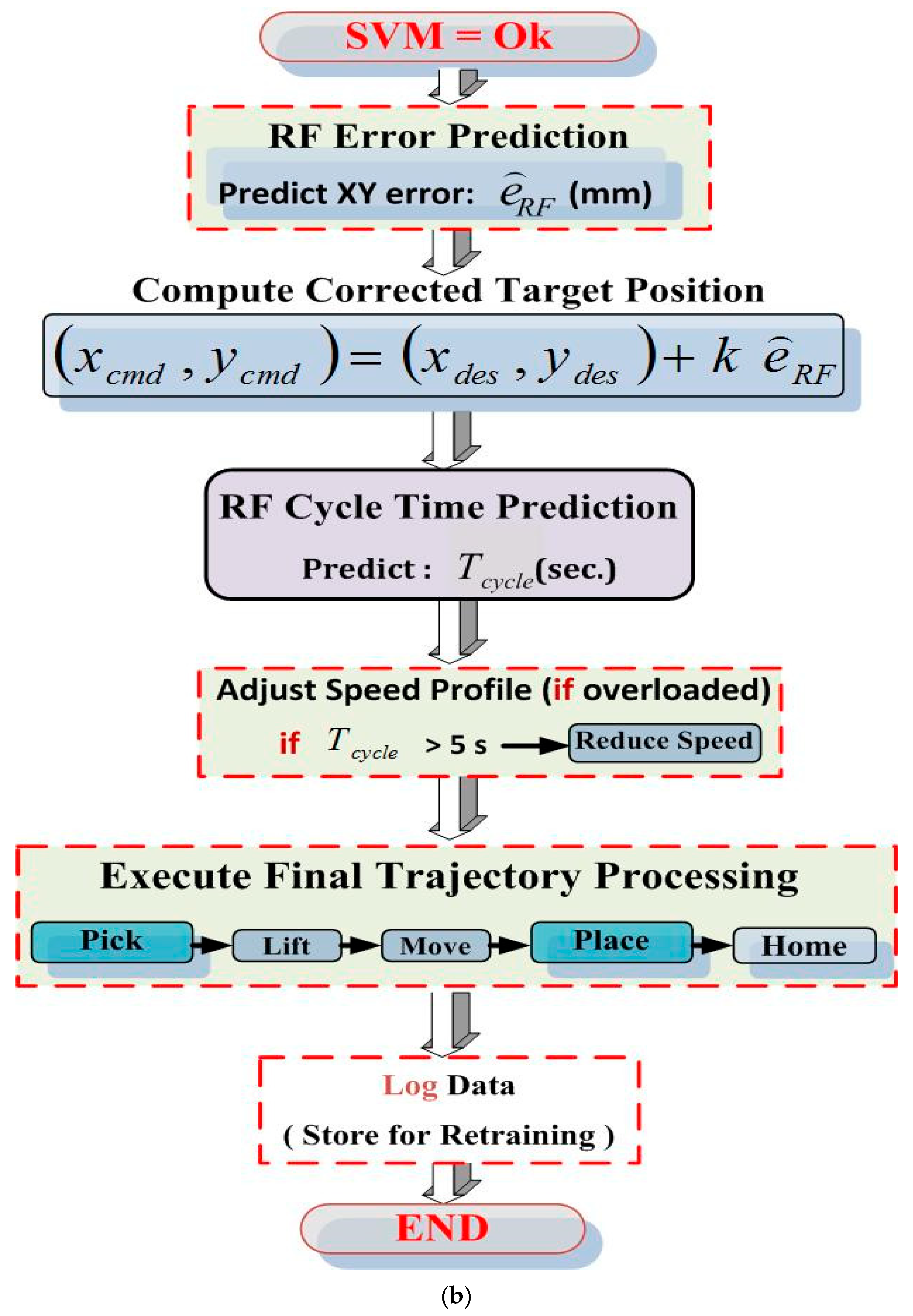
Figure 11 summarizes the ML-driven decision pipeline used in the SCARA robot. Low-level actuation and sensing are handled by the Arduino controller, while all inference runs on a supervisory PC at 50 Hz. Sensor packets are collected in a
sliding buffer, from which nineteen features are computed in real time. The SVM model then evaluates grasp success in ≈6
; if the probability is below
, corrective actions such as increased grip force, reduced speed, and XY micro-alignment are applied, reducing failure cases by
. When the SVM approves the attempt, the RF-models are triggered, as shown in
Figure 11b. The first predicts the expected XY error to refine the commanded target, while the second estimates the cycle time and adjusts speed if overload is detected. RF inference completes in ≈8.7
, keeping the total ML overhead near
—less than
of the robot’s
mechanical cycle.
Table 11 summarizes the measured timing performance of the ML for the SCARA Platform. The results show that all processing steps comfortably fit within the
communication interval, with a total overhead of ≈14
.
The suggested robot was evaluated according to the ISO 9283 standard [
31] for repeatability and accuracy as shown in
Table 12. Five representative target points within the robot’s workspace were executed 30 times each, resulting in 150 placement trials. The SCARA Platform achieves an average positional error of
with a standard deviation of
, corresponding to an ISO 9283 repeatability of
. These values indicate stable short-term precision and consistent positioning performance across all tested points.
Table 13 compares the baseline PID controller with the proposed ML-enhanced control strategy. The integration of SVM-based failure prediction and RF-based error compensation significantly improves task execution. The RMS positioning error drops from
to
, while repeatability improves from
to
. The success rate also increases by
, and a slight reduction in cycle time is observed due to more stable corrective actions. These results demonstrate that the ML framework not only improves accuracy but also enhances consistency and operational efficiency, particularly under conditions where mechanical backlash affects the PID response.
The improved model, depicted in
Figure 11, introduces a data-driven layer employing SVM and RF algorithms to optimize motion parameters and predict the success rate of each PAPO attempt in real time.
Integrating ML algorithms into the PAPO introduces a self-adaptive layer that enables the SCARA robot to handle variability in object size, mass, and position with improved precision. The hybrid use of SVM and RF allows both categorical classification (task success) and continuous prediction (expected error and completion time). This combination effectively improves decision quality and reduces manual-tuning efforts, which are common in purely rule-based control systems.
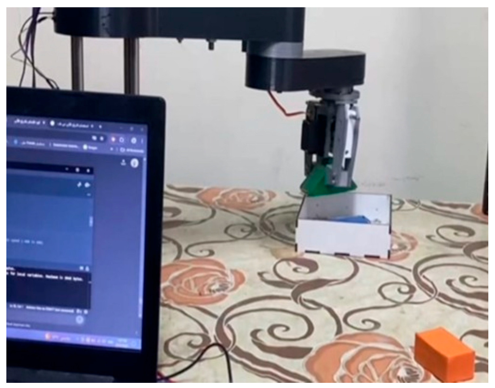
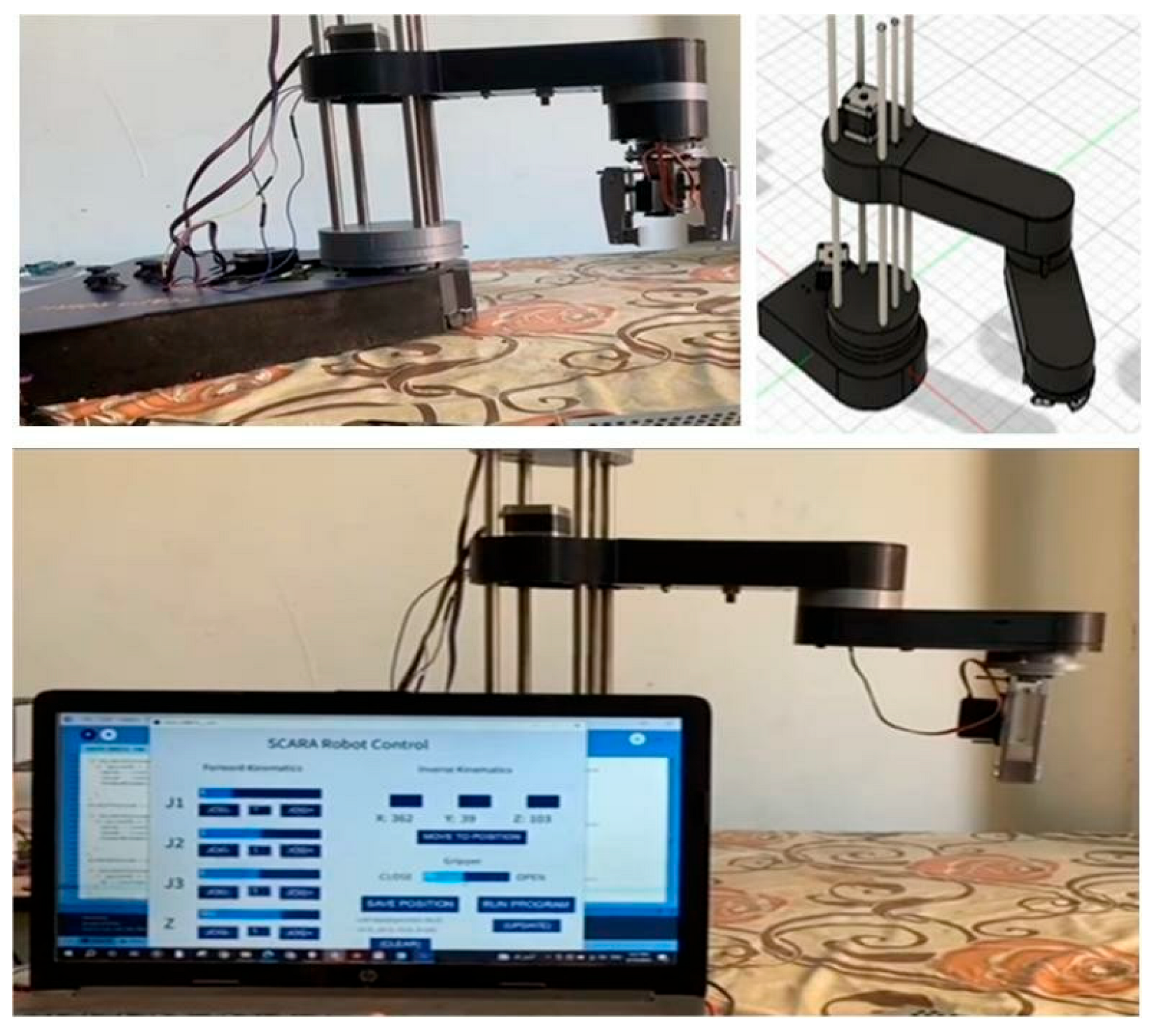
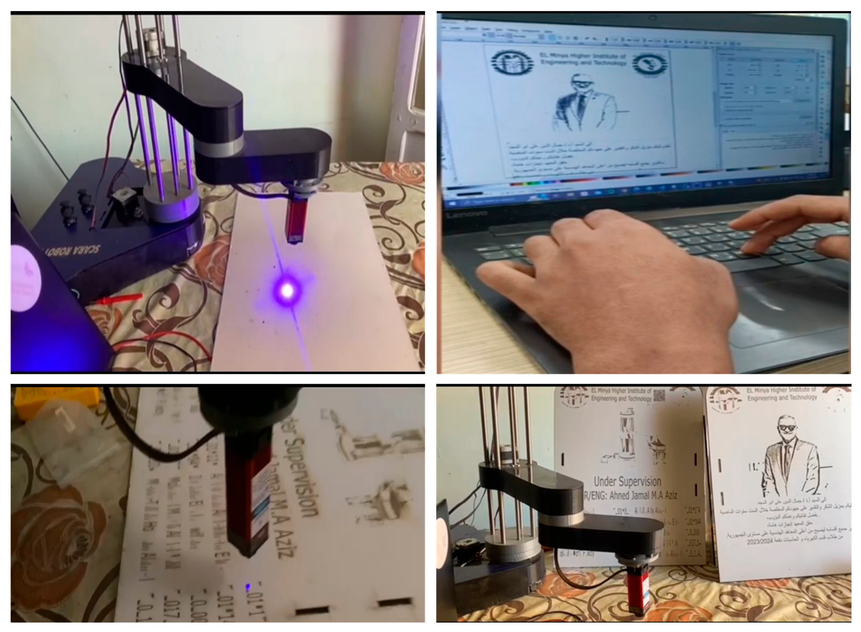
Figure 12 shows the PAPO for the implemented SCARA robot test where the implementing robot is recognized and trained to recognize different colors and geometric shapes.
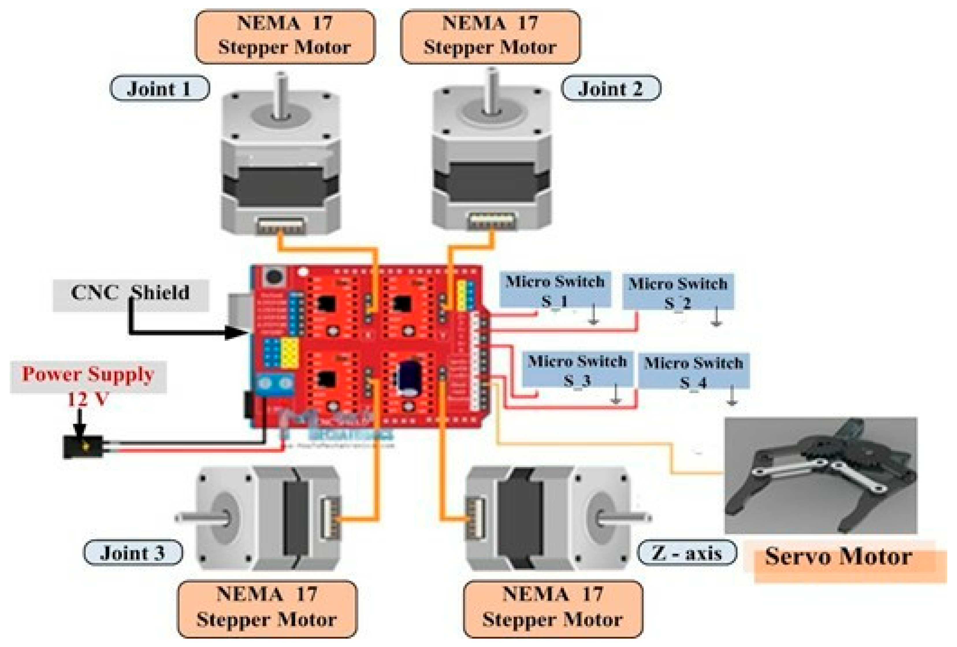
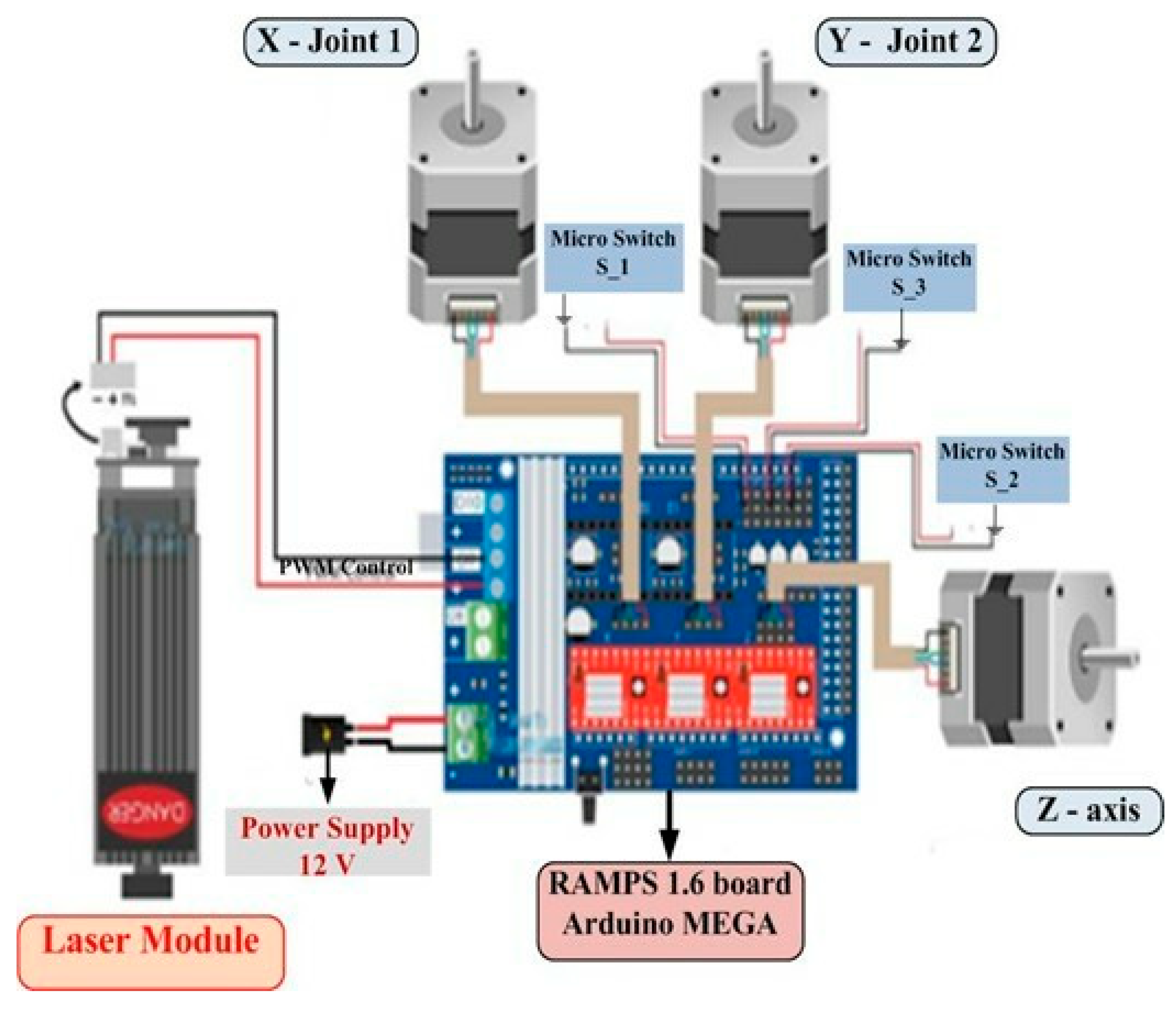
Some M4-bolts and nuts to secure the gripper to the robot arm can be used. A robotic system including three stepper-motors and a servo-motor is intended to be controlled by the PAPO code. It makes it possible to
Use limit switches to homing the motors.
Use serial input to receive movement and position commands.
Manage a servo-gripper-motor.
Store and carry out movement patterns.
As it continuously checks for fresh input, the code is set up to parse commands, store positions, regulate serial communication, and execute those positions.




 ,
,