Article

Multi-Band Unmanned Aerial Vehicle Antenna for Integrated 5G and GNSS Connectivity

by
Suguna Gunasekaran
,
Manikandan Chinnusami
*,
Rajesh Anbazhagan
*,
Karunyaa Sureshkumar
and
Shreela Sridhar
School of Electrical and Electronics Engineering, SASTRA University, Thanjavur 613401, Tamil Nadu, India
*
Authors to whom correspondence should be addressed.
Telecom 2025, 6(2), 38; https://doi.org/10.3390/telecom6020038
Submission received: 17 April 2025 / Revised: 23 May 2025 / Accepted: 30 May 2025 / Published: 3 June 2025

Abstract

This paper proposes a dual-band antenna to support 5G communication with linear polarization and the global navigation satellite system (GNSS) band with circular polarization. A single inverted T-shaped patch antenna with a defective ground was designed on the Schott Foturan II (Ceramized 560 degrees) substrate. Then, an L-shaped stub and slot were inserted into the ground to achieve the 5G and GNSS bands. The antenna was then designed as a 1 × 2 multiple-input and multiple-output (MIMO) antenna to increase the directivity. A square ring-shaped frequency selective surface (FSS) was intended on the FR-4 substrate to improve the gain of the MIMO antenna. The FSS MIMO antenna increased the 3D gain from 2.8 to 5.4 dBi for the GNSS band and from 4.9 to 6.43 dBi for the 5G n79 band. The proposed antenna can receive and transmit the frequency bands covering sub-6 GHz 5G band n79 (4400–5000 MHz) and GNSS band E6 (1260–1300 MHz), respectively. A multi-port unmanned aerial vehicle antenna was fabricated, and its performance was characterized in terms of bandwidth, axial ratio, and gain.

1. Introduction

In today’s rapidly changing world, the need for smooth connectivity and accurate navigation in vehicular networks is in high demand. There is an urgent need for technologies in vehicular networks to improve traffic management, increase road safety, and pave the way for autonomous driving as our cities and roads become more crowded. That is why the global navigation satellite system (GNSS) and the fifth generation technology (5G) have become revolutionary. The 5G cellular network technology is perfect for facilitating the vehicle-to-everything (V2X) communication because it promises unmatched speed, reduced latency, and extensive connectivity. At the same time, precise positioning and timing data are essential for fleet management, location-based services in cars, and navigation assistance, which are ensured by an in-built satellite navigation system. GNSS and 5G aim to enhance the efficiency, safety, and positioning for seamless communication across vehicular networks. In [1], a circularly polarized quad-band antenna was designed and fabricated to resonate in 5G n77, 5G n78, GNSS, and wireless fidelity (Wi-Fi) 6E bands. A single-patch L-shaped structure with a defective ground was developed on an FR4 substrate. It enhanced the gain of 4.56, 2.28, 4.26, and 4.30 dBi with circular polarization.
In [2], a planar antenna of four bands was designed for the GNSS/wireless local area network (WLAN)/X-band applications. It was designed and fabricated on the FR4 material as a multi-band monopole antenna for vehicular rooftop applications. This single-port antenna operates in multiple bands, with peak gains of 5.7, 3.79, and 5.4. In [3], the antenna covering the 5G, sub-6 GHz, and LTE bands was designed on an FR4 substrate. The covered frequency achieved a gain of 3 dBi. In [4], multiple-input and multiple-output (MIMO) antennas needed for high-speed communication systems are discussed. The shift to MIMO antennas has advantages such as better channel capacity and the ability to concentrate radio frequencies on specific users. At the same time, difficulties faced while creating a compact MIMO antenna were also addressed. In [5], a wideband MIMO antenna with eight elements embedded on the FR4 material for the whole 5G band covering n78 and Wi-Fi at 5 GHz was designed and fabricated. Various performance analyses, such as the envelope correlation coefficient (ECC) and diversity gain, were calculated to validate the projected MIMO antenna’s performance. In [6], a circularly polarized single-port antenna with a circular slot in the ground was designed and fabricated for wireless communication networks with dimensions of 50 × 50 mm. By introducing semicircular loop feeding and adding a slit in the ground, multiple circular polarization resonant modes could be simulated simultaneously.
In [7], a 4 × 4 MIMO antenna for 5G networks was developed. This antenna operates across dual bands, explicitly targeting the 5G n78 and n79 frequencies. Within this framework, the two bands utilize the essential TM11 mode. Additionally, the higher-order mode is addressed through a combination of quasi-TM11 and TM0,1/2 modes. In [8], a four-port MIMO antenna was designed and fabricated for 5G n79 applications. The reversed L-shaped antenna with modifications at the ground plane and all four radiating elements were perpendicular to each other, such that a minimum isolation of 25 dB was achieved. This antenna works on a single band, with a peak gain of 2.8 dBi. In [9], a single antenna was designed and fabricated on FR4, that resonates at both 5G and GNSS bands. It was linearly polarized for 5G and right-hand circularly polarized for the GNSS, and it was suitable for automotive flat antenna modules. In [10], a four-element antenna array with right-hand circular polarization and a single feed was designed. A circular patch antenna was developed on Rogers TMM10i with a radius of 120 to achieve an RHCP. This design is tailored for applications in the upper L-band of the GNSS and has a defective ground structure and MT-30 microwave absorber to achieve high isolation. In [11], an antenna system for integrating 5G and the right-hand circularly polarized GNSS L1/L5 band was proposed; this can be used on a vehicle’s roof inside low-profile housing.
In [12], an antenna pair for mobile terminals was designed and fabricated on the FR4 material with a MIMO configuration for the 5G n77/n78/n79 5G bands; it satisfies all MIMO parameters and is capable of good data transmission. However, it operates in only one band, with an enhanced gain of 4.2–8.2 dBi. In [13], a MIMO multi-band antenna was designed and fabricated for 5G, WI-FI-6, and WLAN devices using an FR4 substrate. This MIMO multi-band antenna was designed by duplicating a single-element antenna and placing it orthogonally to the first element. The multi-port, multi-band antenna improves the gain to 2.2, 3.4, and 3.41 dBi. In [14], an eight-element MIMO antenna for ultra-wideband applications was designed. It also achieved good MIMO parameters, making it suitable for portable ultra-wideband applications. In [15], a jug-shaped coplanar waveguide for ultra-wideband MIMO applications was designed and fabricated on FR4 with a size of 60 × 60 mm. Here, the MIMO port components were positioned orthogonally to each other for self-decoupling [16]. This MIMO antenna was designed for future 5G devices; it achieves a gain of 3.4 dBi, has an efficiency of over 65% over the entire bandwidth and a maximum value of 92.7% at the resonant frequency.
An E-shaped microstrip patch antenna array was designed, and electronic beam steering with high directivity for space applications was proposed [17]. Further, increasing the number of radiating elements improved the antenna’s gain value to 7.01 dBi. In [18], a two-element multi-band MIMO antenna was developed and manufactured to cater to Ka-band satellite communication, millimeter-wave technology, 5G networks, and forthcoming 6G wireless communication systems. In [19], the MIMO design was compared to dual-band, ultra-wideband, and circularly polarized antennas. The antenna performance was analyzed based on the envelope correlation coefficient (ECC), efficiency, isolation techniques, gain, and channel capacity loss (CCL). Finally, in [20], a coplanar waveguide with a circularly polarized rectangular slot antenna was designed and fabricated for the GNSS in vehicular applications. It was designed according to the direction in which windshields are tilted, with a glass substrate. This work developed an inverted T-shaped patch with a defective ground for dual-port, dual-band, dual-polarized antennas with maximum gain. The comparison analysis of the proposed approach with the literature is included in Table 1 for ease of understanding. The positioning of a dual-port antenna on a drone for outdoor 5G and GNSS connectivity is displayed in Figure 1. The main contributions of this paper are as follows:
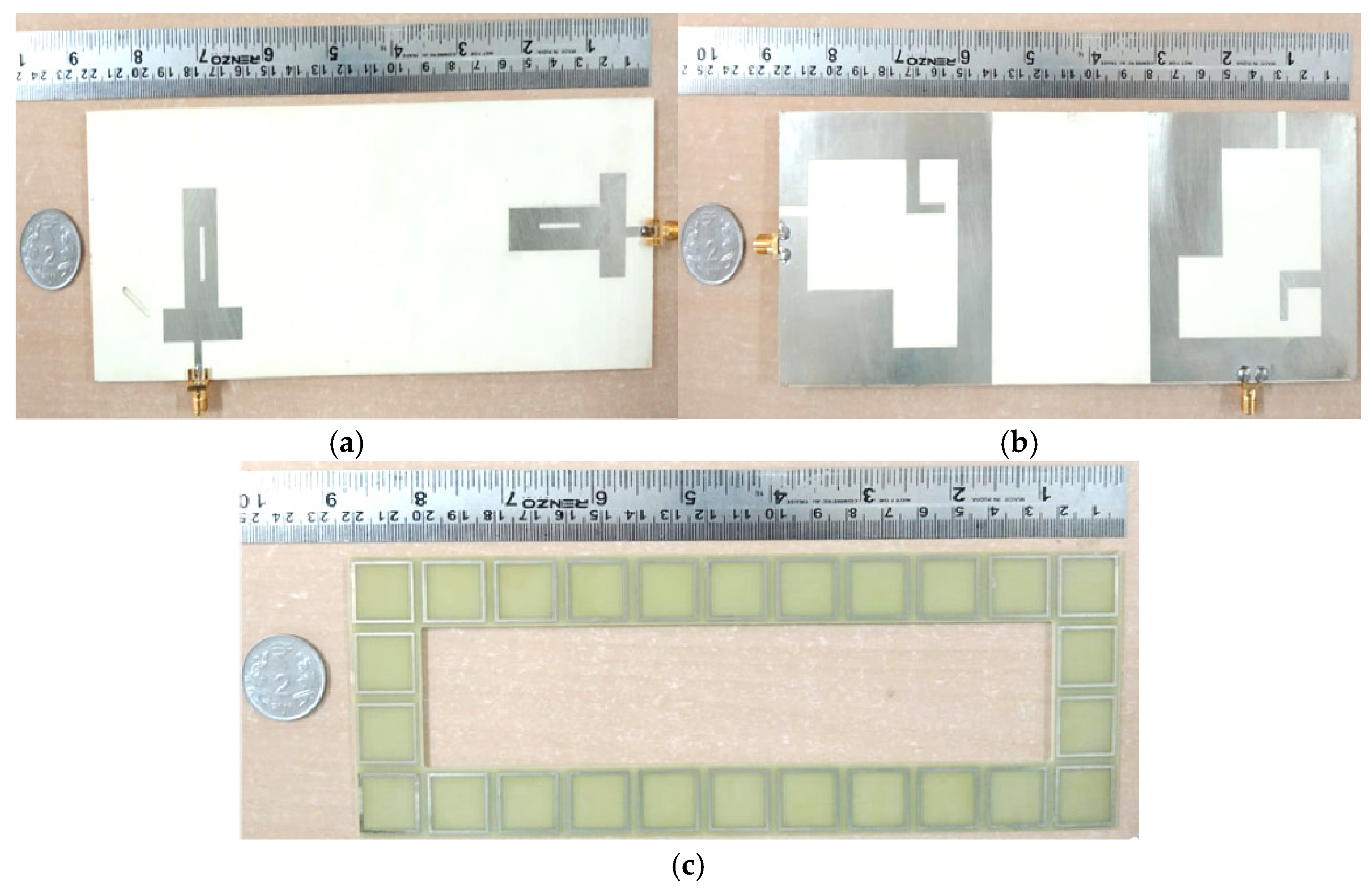
A single-port inverted T-shaped antenna with defected ground was designed to resonate in the GNSS and 5G bands with circular polarization.
Appropriate orthogonal placement of a dual-port MIMO antenna to reduce the electromagnetic interaction among the antenna structures.
A single square ring-shaped frequency selective surface (FSS) was designed for broadband coverage.
Investigation of an FSS integrated dual-port MIMO antenna for outdoor 5G and GNSS applications.

2. Dual-Port Inverted T-Shaped MIMO Antenna and Analysis

A dual-port inverted T-shaped multi-port antenna was designed with a defective ground. Initially, the T-shaped patch was designed with slots to achieve the dual bands of the 5G and GNSS frequencies. To tune the frequency and achieve circular polarization, the L-shaped stub with a defective ground structure was introduced. The schematics of a single-patch antenna, a multi-port antenna, and a multi-port antenna with an FSS are depicted in Figure 2, respectively. The single-patch antenna is fed through a micro-strip feedline. The feedline is connected to an inverted T-shaped patch with a slot introduced in the center. The inverted T-shaped patch is printed on a Schott Foturan II (Ceramized at 560 degrees) with ε r = 5.8, and the frame ground is fabricated on the bottom of the substrate with appropriate slots on the ground. Here, H refers to the substrate thickness, and G denotes the length and width of the substrate. The resultant values for each parameter are listed below in Table 2.
This dual-band single-patch element was studied for the GNSS E6 band with circular polarization and the 5G n79 band with linear polarization. Figure 3 represents the S11 parameter of a single-patch antenna, a MIMO antenna, and a MIMO antenna with an FSS. The structure attains the required reflection coefficient value of less than −10 dB for both bands. Further, the MIMO antenna with a 1 × 2 configuration evolved from the single-patch antenna, as shown in Figure 4, to increase gain and directivity. Both antenna elements are oriented at 90 degrees to each other. The dual-port elements are positioned in a space of λ =   60 mm. The main application of this antenna is in vehicular networks. The required S11 value of less than −10 dB was also achieved for the MIMO antenna.
The single-patch radiating antenna was constructed in the form of an inverted T-shaped patch with a defective ground layer to achieve dual-band frequency operation. The ABCD matrix is defined for a 2-port network in terms of the total current and voltage. The equation is as follows:
V 1 I 1 = A B C D   V 2 I 2
The mathematical analysis of ABCD parameters is carried out by using the total transfer matrix, which includes a transmission line, an open circuit, and a defective microstrip structure. The overall reflection coefficient (S11) was analyzed by using ABCD parameter matrices. The GNSS band of S11 was derived using a lossy transmission line (TA1), the electrical length ( θ ) , and the characteristic impedance (Z0) of the ABCD matrix:
T A 1 = A B C D = cos θ j Z i m p   sin θ j sin θ Z i m p cos θ = 0.847 j 26.5 j 0.0106 0.847
The ABCD matrix for the open circuit (TB) is as follows:
T B 1   = A B C D = 1 0 1 Z i 1 = 1 0 j 0.0054 1
where Z i = j Z 0 cot θ .
Then, the defective ground structure was evaluated by using L and C values:
T C 1   = A B C D = 1 Z s 0 1 = 1 j 0.00223 0 1
where Z s = 1 j ω L + j ω C , ω = 2 π f , and f is the operating frequency.
The total transfer matrix (Ttotal) is as follows:
T t o t a l 1 = T A 1   T B 1 T c 1 T B 1 T A 1
  T t o t a l 1 = A B C D = 0.298 j 40.73 j 0.0219 0.311
The scattering parameter of the reflection coefficient is calculated using Equation (7):
S 11 = A + B Z i m p C Z i m p D A + B Z i m p + C Z i m p + D
S 11 = 0.173 j 0.048
S 11 = 14.91   d B
By using the ABCD parameters, the reflection coefficient (S11) was derived. The derived S11 was −14.91 dB at 1.3 GHz, which was closest to the simulated value of −16.835 dB. Similarly, the reflection coefficient for the 5G band was derived by using the ABCD matrix as follows:
T A 2 = A B C D = cos θ j Z i m p   sin θ j sin θ Z i m p cos θ = 0.580 j 40.7 j 0.0162 0.580
The ABCD matrix for the open circuit (TB) is as follows:
T B 2   = A B C D = 1 0 1 Z a 1 = 1 0 j 0.0032 1
Then, the defective ground structure was evaluated by using the L and C values:
T C 2   = A B C D = 1 Z s 0 1 = 1 j 0.0004 0 1
The total transfer matrix (Ttotal) is as follows:
T t o t a l 2 = T A 2   T B 2 T c 2 T B 2 T A 2
T t o t a l 2 = A B C D = 0.476 j 36.23 j 0.0198 0.404
The scattering parameter of the reflection coefficient (S11) is calculated as follows:
S 11 = 0.1257 j 0.0225
S 11 = 17.87 d B
By using the ABCD parameters, the reflection coefficient (S11) was derived. The derived S11 was −17.87 dB at 4.58 GHz, which was closest to the simulated value of −25.86 dB.
Figure 5 represents the graph of the reflection coefficient (S11/S22), isolation loss (S12), and insertion loss (S21) for the proposed 1 × 2 MIMO antenna design. From the graph, it is understood that there is no mutual coupling between the patches since there is no overlap between the S11/S22 and the S21 and S12 graphs.
An additional structure called a frequency selective surface was added to the MIMO antenna to further enhance the gain and directivity. A frequency selective surface (FSS) refers to a thin, repeating surface, such as a microwave oven screen, designed to interact with electromagnetic fields by selectively reflecting, transmitting, or absorbing them based on frequency. FSS structures typically exhibit two- or three-dimensional periodic patterns, consisting of a metal sheet with an infinite array of metal apertures or patches printed on a dielectric substrate. These surfaces act as spatial filters, wherein incoming electromagnetic waves are either partially or entirely reflected or transmitted over specific frequency ranges, depending on the design of the array elements.
FSS are categorized into four types based on their filtering characteristics: low-pass, high-pass, band-stop, and band-pass filters. A band-stop FSS unit cell was constructed over an FR4 substrate of thickness T, as displayed in Figure 6. The specification of the unit cell is presented in Table 3. Figure 7 represents the reflection factor of the FSS unit cell. An inverted array of an FSS was combined with the MIMO element at the backside, as displayed in Figure 8.
The proposed MIMO antenna was converted to a MIMO with an FSS structure to increase gain and directivity further. The FSS unit cell was transformed into an array and placed over a 1.6 mm thick FR4 substrate. This design was inverted and placed at the bottom of the MIMO antenna with an air gap of 10.44 mm, as shown in Figure 8. The scattering factor of the MIMO elements represents no mutual coupling even after placing the FSS structure, as displayed in Figure 9. The scattering factor of the MIMO antenna with an FSS was achieved for the required bands with a good reflection coefficient.

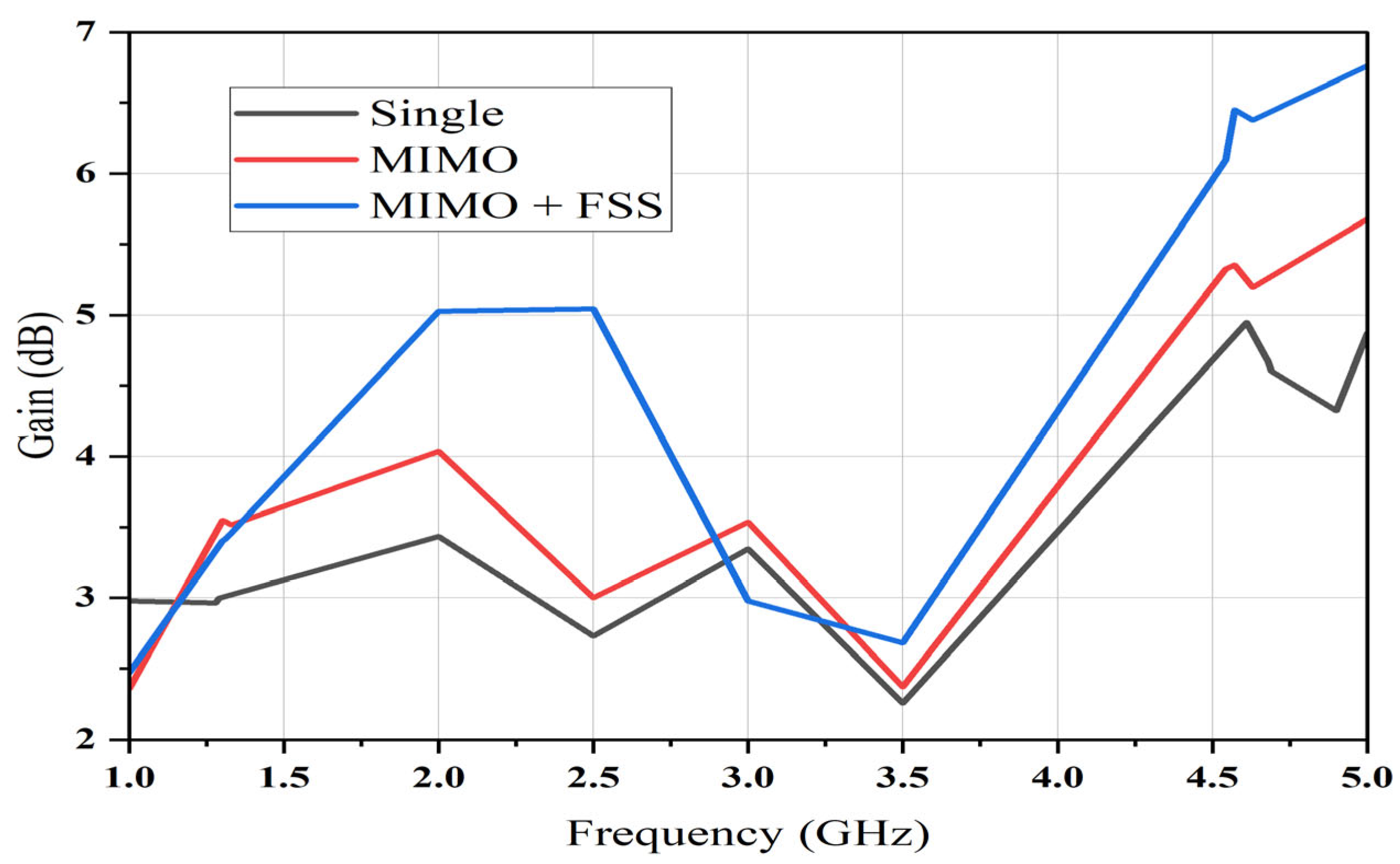
2.1. Gain Parameter Analysis

An antenna’s 3D gain indicates how successfully it sends and receives signals in every direction in space. It functions similarly to a measurement of its total efficacy in three dimensions. Antenna performance in capturing or transmitting signals from different angles is improved with a higher 3D gain. The lower frequency of the GNSS band of the single-patch antenna achieved a gain of 2.9 dB, of the MIMO antenna—3.45 dB, while that of the MIMO antenna with an FSS was 5.44 dBi, as shown in Figure 10. Similarly, for the higher frequency band of 5G, the antennas achieved a gain from 4.9 to 6.43 dBi.

2.2. Axial Ratio Parameter Analysis

An antenna’s axial ratio represents how effectively the radiation element preserves the transparency of the polarization. Better polarization performance is indicated by a lower axial ratio, and this is important for reducing signal distortion in communication systems. Figure 11 shows the comparison results of the single-port antenna, the MIMO antenna, and the MIMO antenna with an FSS.
In this work, the various stages of the antenna maintained the AR value of ≤3 dB at the resonance frequency of the 5G and GNSS bands. At the frequencies of 1.2–1.3 GHz, it achieved the axial ratio of 1.105 dB and circular polarization. At the higher frequency of the 5G band, the axial ratio was greater than 3 dB, with linear polarization.

2.3. VSWR Parameter Analysis

The voltage standing wave ratio (VSWR) shows how well a transmission line or radiating element stabilizes the impedance of the system or devices. Reduced VSWR values, preferably near 1, indicate reduced signal reflection and improved impedance matching. Poor impedance matching is indicated by high VSWR values, usually exceeding 2, which can cause signal loss and possibly damage to equipment. The VSWR for all the configurations is shown in Figure 12.

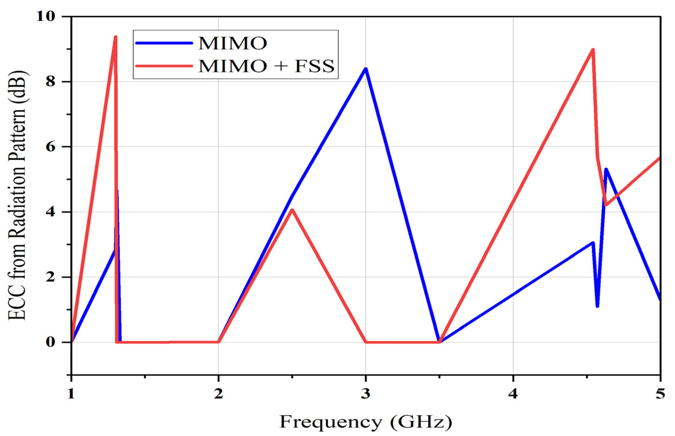
2.4. Envelope Correlation Coefficient

As a diversity parameter, the envelope correlation coefficient (ECC) can be derived from radiation patterns or S-parameters, but ECC values obtained from far-field radiation patterns are generally preferred. This preference stems from the fact that the ECC calculated from radiation patterns effectively illustrates the independence of radiation patterns among multiple radiating elements in MIMO systems. Additionally, it is essential to consider that many planar antennas experience loss, underscoring the need for caution when relying on S-parameters for ECC determination. The computed ECC values are below 0.01, which is very good for the proposed application. Figure 13 shows the ECC values using an S-parameter, and Figure 14 shows the ECC values using a radiation pattern.

2.5. Diversity Gain

Communication reliability and performance are improved when additional elements are used at the transceiver. Multi-path propagation, interference, and signal fading can be reduced in MIMO systems using diverse signal routes, such as spatial, polarization, or frequency diversity. Better data speed, more coverage, and improved system reliability overall are the outcomes thereof, especially in challenging wireless environments. Diversity gains of more than 9.99 were achieved for the MIMO antenna and the MIMO antenna with an FSS, as shown in Figure 15.

2.6. Mean Effective Gain

Mean effective gain (MEG) is the diversity metric within multi-port elements, representing the relationship between the power received by the multi-port elements and that received by an isotropic antenna. Theoretically, the MEG value for a multi-port element should fall within the range of −3 dB to −12 dB. This was achieved, as shown in Figure 16.

2.7. Total Active Reflection Coefficient

In multi-port elements, the total active reflection coefficient (TARC) is utilized to analyze the diversity characteristics of the antenna. A multi-port element must have a TARC value of less than −10 dB. Figure 17 displays the proposed FSS-based MIMO antenna with the simulation value ≤ −10 dB in the dual-frequency bands of 4.4–5 GHz (n78) and 1.2–1.3 GHz (GNSS).

2.8. Current Distribution

The E-field distribution of the single-patch antenna, the MIMO antenna, and the MIMO antenna with an FSS at the GNSS and 5G bands is presented in Figure 18, Figure 19, and Figure 20, respectively. The surface current is uniformly dispersed from the feed to the radiating element. In the single-patch element, the strong current flow on the top and left side of the patch at a lower frequency of 1.28 GHz is displayed in Figure 18a. At a higher frequency of 4.69 GHz, the current mainly concentrated on the right-side corner of the patch, and a small amount of current flows concentrated along the edge, as displayed in Figure 18b. The same current distribution was observed in the MIMO antenna at ports 1 and 2 for dual frequencies, as presented in Figure 19a–d. Furthermore, the MIMO antenna with an FSS enhanced the current flow in all directions and improved the performance of the higher frequency band at ports 1 and 2 when compared to the antenna without an FSS, as illustrated in Figure 20a–d.
The proposed dual-port antenna and an FSS were developed, and the anterior and posterior views of the prototype are displayed in Figure 21. The fabricated dual-port element’s scattering parameter was measured using VNA N9917A, as displayed in Figure 22a. The experimental S-parameter values S11 and S12 are displayed in Figure 22b,c. The measured reflection coefficient achieved the reflection coefficient S11 < −10 dB at the dual frequency of 1.3 and 4.5 GHz, which matched the simulated results well, as shown in Figure 22d. At higher frequencies, variations in the measured reflection coefficient can occur due to imperfections in fabrication and soldering. The antenna was tested with a calibrated VNA and 50-Ohm SMA cables. However, the results showed variability because of the high-frequency sensitivity to cable and environmental conditions. Moreover, the proposed fabricated two-port MIMO antenna enhanced the isolation performance among dual ports, with isolation less than −20 dB at the GNSS and 5G frequency bands. The overall comparison results of the single-patch antenna, the MIMO antenna, and the MIMO antenna with an FSS are shown in Table 4.

3. Conclusions

A dual-port FSS-based MIMO antenna was developed for outdoor 5G-GNSS unmanned aerial vehicle communication. An inverted T-shaped single-patch element was orthogonally placed to avoid mutual coupling and achieve self-decoupling. A square-ring FSS was implemented using an array of 4 × 11-unit cells. The presented 1 × 2 array antenna operates in the dual-frequency bands of 1.28 GHz (GNSS) and 4.58 GHz (5G) with dual polarization. It achieved a reflection coefficient S11 < −10 dB and a mutual coupling S21 < −20 dB. At a lower frequency, the MIMO + FSS antenna enhanced the gain by 5.4 dBi, with an AR of 1.10 dB, and operated under circular polarization. The higher frequency achieved a gain of 6.43 dBi with an AR of 4.4 dB, achieving linear polarization. The MIMO parameters, such as the ECC < 0.5, DG < 9.9, MEG < −3 dB, and TARC < −10 dB, were within the limits. The measured and simulated results of S11 were good; therefore, this antenna is suitable for outdoor UAV applications.

Author Contributions

Conceptualization, S.G.; data curation, M.C.; methodology, R.A.; software, K.S.; validation, M.C. and R.A.; visualization, S.S.; writing—original draft preparation, S.G.; writing—review and editing, R.A. All authors have read and agreed to the published version of the manuscript.

Funding

We would like to thank and acknowledge the IIT Tirupati Navavishkar I-Hub Foundation (IITTNiF), the National Mission on Interdisciplinary Cyber-Physical Systems (NM-ICPS), and the Department of Science and Technology (DST), India, for their financial support (SASTRA-IITTNiF/5GNP/2024-25) and SASTRA Deemed University, India, for providing the necessary resources and support.

Data Availability Statement

The authors declare that any data related to this research will be made available upon request.

Conflicts of Interest

The authors confirm that there are no known conflicts of interest associated with this publication and that there was no significant financial support for this work that could have influenced its outcome.

Abbreviations

The following abbreviations are used in this manuscript:
MIMOMultiple-input and multiple-output
FSSFrequency selective surface
VSWRVoltage standing wave ratio
GNSSGlobal navigation satellite system
TARCTotal active reflection coefficient
MEGMean effective gain
ECCEnvelope correlation coefficient
V2XVehicle-to-everything
WLANWireless local area network
CCLChannel capacity loss

References

  1. Liu, X.; Wang, H.; Yang, X.; Wang, J. Quad-Band Circular Polarized Antenna for GNSS, 5G and WIFI-6E Applications. Electronics 2022, 11, 1133. [Google Scholar] [CrossRef]
  2. Chandra, R.J.; Ali, T.; Kumar, O.; Pai, M.M. A planar rectangular slot multi-band patch antenna for GNSS/WLAN/X-band applications. Mater. Today Proc. 2020, 28, 2279–2285. [Google Scholar] [CrossRef]
  3. Ibrahim, A.S.; Yacoub, A.M.; Aloi, D.N. A 3-dimensional multi-band antenna for vehicular 5G sub-6 GHz/GNSS/V2X applications. Int. J. Antennas Propag. 2022, 2022, 5609110. [Google Scholar] [CrossRef]
  4. Tiwari, P.; Gahlaut, V.; Kaushik, M.; Rani, P.; Shastri, A.; Singh, B. Advancing 5G connectivity: A comprehensive review of MIMO antennas for 5G applications. Int. J. Antennas Propag. 2023, 2023, 5906721. [Google Scholar] [CrossRef]
  5. Jiang, J.-Y.; Su, H.-L. A wideband eight-element MIMO antenna array in 5G NR n77/78/79 and WLAN-5GHz bands for 5G smartphone applications. Int. J. Antennas Propag. 2022, 2022, 8456936. [Google Scholar] [CrossRef]
  6. Wang, L.; Yao, B.; Fang, W.; Huang, C.; Huang, Y.; En, Y. New Circular-Slot Circularly Polarized Antenna with Modified Characteristic. Int. J. Antennas Propag. 2022, 2022, 5458069. [Google Scholar] [CrossRef]
  7. Chang, L.; Wang, H. Dual-Band Four-Antenna Module Covering N78/N79 Based on PIFA for 5G Terminals. IEEE Antennas Wirel. Propag. Lett. 2022, 21, 168–172. [Google Scholar] [CrossRef]
  8. Ali, H.; Ren, X.-C.; Bari, I.; Bashir, M.A.; Hashmi, A.M.; Khan, M.A.; Majid, S.I.; Jan, N.; Tareen, W.U.K.; Anjum, M.R. Four-Port MIMO Antenna System for 5G n79 Band RF Devices. Electronics 2022, 11, 35. [Google Scholar] [CrossRef]
  9. Abdul-Rahman, E.; Aloi, D.N. Design of a multi-function global navigation satellite system and 5G cellular antenna structure for automotive applications using characteristic mode analysis. IET Microw. Antennas Propag. 2023, 17, 863–871. [Google Scholar] [CrossRef]
  10. Madni, A.; Khan, W.T. Design of a Compact 4-Element GNSS Antenna Array With High Isolation Using a Defected Ground Structure (DGS) and a Microwave Absorber. IEEE Open J. Antennas Propag. 2023, 4, 779–791. [Google Scholar] [CrossRef]
  11. Yacoub, A.; Aloi, D.N. Low-Profile Automotive Antenna Systems for MIMO 5G and L1/L5 GNSS Communications. In Proceedings of the 2022 16th European Conference on Antennas and Propagation (EuCAP), Madrid, Spain, 27 March–1 April 2022; pp. 1–4. [Google Scholar] [CrossRef]
  12. Du, K.; Wang, Y.; Zhang, L.; Hu, Y. Design of Wideband Decoupling Antenna Pairs for 5G Portable Devices at N77/N78/N79 Bands. Micromachines 2022, 13, 1964. [Google Scholar] [CrossRef] [PubMed]
  13. Ali, A.; Munir, M.E.; Marey, M.; Mostafa, H.; Zakaria, Z.; Al-Gburi, A.J.A.; Bhatti, F.A. A Compact MIMO Multi-band Antenna for 5G/WLAN/WIFI-6 Devices. Micromachines. 2023, 14, 1153. [Google Scholar] [CrossRef] [PubMed]
  14. Addepalli, T.; Desai, A.; Elfergani, I.; Anveshkumar, N.; Kulkarni, J.; Zebiri, C.; Rodriguez, J.; Abd-Alhameed, R. 8-Port Semicircular Arc MIMO Antenna with an Inverted L-Strip Loaded Connected Ground for UWB Applications. Electronics 2021, 10, 1476. [Google Scholar] [CrossRef]
  15. Ahmad, S.; Khan, S.; Manzoor, B.; Soruri, M.; Alibakhshikenari, M.; Dalarsson, M.; Falcone, F. A Compact CPW-Fed Ultra-Wideband Multi-Input-Multi-Output (MIMO) Antenna for Wireless Communication Networks. IEEE Access. 2022, 10, 25278–25289. [Google Scholar] [CrossRef]
  16. Shoaib, N.; Shoaib, S.; Khattak, R.Y.; Shoaib, I.; Chen, X.; Perwaiz, A. MIMO Antennas for Smart 5G Devices. IEEE Access. 2018, 6, 77014–77021. [Google Scholar] [CrossRef]
  17. Nadar, K.P.; Jeyaprakasam, V.; Mariapushpam, I.T.; Vivekanand, C.V.; Eswaralingam, A.D.; Louis, M.T.; Raj, J.X.A.; Jibril, H.A.; Chellappa, A.S.; Muthukutty, R.K.; et al. Design and Analysis of Microstrip Patch Antenna Array and Electronic Beam Steering Linear Phased Antenna Array with High Directivity for Space Applications. ACS Omega 2023, 8, 43197–43217. [Google Scholar] [CrossRef] [PubMed]
  18. Kumar, A.; Pattanayak, P.; Verma, R.K.; Sabat, D.; Prasad, G. Two-element MIMO antenna system for multi-band millimeter-wave, 5G mobile communication, Ka-band, and future 6G applications with SAR analysis. AEU-Int. J. Electron. Commun. 2023, 171, 154876. [Google Scholar] [CrossRef]
  19. Sharma, P.; Tiwari, R.N.; Singh, P.; Kumar, P.; Kanaujia, B.K. MIMO Antennas: Design Approaches, Techniques and Applications. Sensors 2022, 22, 7813. [Google Scholar] [CrossRef] [PubMed]
  20. Gharaati, A.; Ghaffarian, M.S.; Mirzavand, R. Transparent Wideband Circularly Polarized GNSS Antenna for Vehicular Applications. IEEE Access. 2021, 9, 130185–130198. [Google Scholar] [CrossRef]
Figure 1. Development of a dual-port MIMO antenna on a drone for 5G and GNSS connectivity.
Telecom 06 00038 g001
Figure 2. Geometry and parameters of (a) the slotted ground, (b) slotted patch, and (c) anterior view of the single-patch element.
Telecom 06 00038 g002aTelecom 06 00038 g002b
Figure 3. S-parameter of the single-patch antenna, the MIMO antenna, and the MIMO + FSS antenna.
Telecom 06 00038 g003
Figure 4. (a) Slotted grounds, (b) anterior view of the proposed 1 × 2 MIMO antenna.
Telecom 06 00038 g004
Figure 5. MIMO antenna: various S-parameters.
Telecom 06 00038 g005
Figure 6. FSS unit cell.
Telecom 06 00038 g006
Figure 7. S-parameter of the FSS unit structure.
Telecom 06 00038 g007
Figure 8. (a) Back view of the MIMO antenna, (b) side view of the MIMO antenna.
Telecom 06 00038 g008
Figure 9. MIMO antenna with an FSS: various S-parameters.
Telecom 06 00038 g009
Figure 10. 3D gain of the single-patch, MIMO, and MIMO + FSS antennas.
Telecom 06 00038 g010
Figure 11. Axial ratio of the single-patch, MIMO, and MIMO + FSS antennas.
Telecom 06 00038 g011
Figure 12. (a) VSWR of the single-patch antenna, (b) VSWR1 of the MIMO antenna (port 1), (c) VSWR2 of the MIMO antenna (port 2), (d) VSWR1 of the MIMO antenna with an FSS (port 1), (e) VSWR2 of the MIMO antenna with an FSS (port 2).
Telecom 06 00038 g012
Figure 13. Envelope correlation coefficient of the dual-port antenna and the dual-port antenna with an FSS obtained from the scattering parameters.
Telecom 06 00038 g013
Figure 14. Envelope correlation coefficient of the dual-port antenna and the dual-port antenna with an FSS obtained from the radiation patterns.
Telecom 06 00038 g014
Figure 15. Diversity gain of the MIMO and MIMO + FSS antennas.
Telecom 06 00038 g015
Figure 16. MEG of the MIMO and MIMO + FSS antennas.
Telecom 06 00038 g016
Figure 17. TARC of the MIMO + FSS antenna.
Telecom 06 00038 g017
Figure 18. E-field distribution of the single-patch antenna (a) at 1.28 GHz and (b) 4.69 GHz.
Telecom 06 00038 g018
Figure 19. E-field distribution of the MIMO antenna without an FSS: (a) port 1 at 1.28 GHz; (b) port 2 at 1.28 GHz; (c) port 1 at 4.69 GHz; and (d) port 2 at 4.69 GHz.
Telecom 06 00038 g019aTelecom 06 00038 g019b
Figure 20. E-field distribution of the MIMO antenna with an FSS: (a) port 1 at 1.28 GHz; (b) port 2 at 1.28 GHz; (c) port 1 at 4.69 GHz; and (d) port 2 at 4.69 GHz.
Telecom 06 00038 g020aTelecom 06 00038 g020b
Figure 21. Prototype of the proposed dual-port element: (a) anterior view; (b) posterior view; (c) FSS.
Telecom 06 00038 g021
Figure 22. Measurement setup: (a) testing of the dual-port element using VNA; (b) measured results of S11; (c) measured results of S12; (d) comparison of the simulated and experimental results.
Telecom 06 00038 g022
Table 1. Comparison of this work with the literature.
ReferenceDimensions (mm)MaterialFrequencyGain (dBi)Antenna TypePolarization
[1]80 × 80 × 1.6FR4WIFI-6E, 5G, n77, n78, and GNSS4.56, 2.28, 4.26, and 4.30SingleCP
[2]60 × 60 × 1.6FR4GNSS, WLAN, X5.7, 3.79, and 5.4Single-
[3]58 × 37 × 17FR4GNSS3Single-
[5]150 × 75 × 7.8FR4(n77/n78/n79) and WLAN-MIMO-
[6]50 × 50 × 0.8-6 GHz4.52SingleRHCP
[8]40 × 40FR45G n782.8MIMO-
[9]75 × 50 × 30FR4GNSS L1, 5G5.2 and 3.9SingleRHCP and LP
[10]125(R) × 5.08Rogers TMM10iGNSS6MIMORHCP
[12]28 × 6FR45G-n77/n78/n794.2–8.2MIMO-
[13]16 × 28 × 1.6FR45.5, 5.5, and 6.5 GHz2.24, 3.49, and 3.41MIMO-
[14]61 × 61 × 1.6FR43.1, 4.7, 6.9 and 9.5 GHz5.6MIMO-
[15]60 × 60 × 1.6FR43–11 GHz3.4MIMO-
[16]312 × 312 × 157Rogers RT-588025.2 GHz8.7MIMO-
[17]40 × 50 × 0.8Rogers RT-58804.17 GHz7.01MIMO-
Proposed40 × 80 × 3.2TUC803BGNSS, 5G n795.44 and 6.43MIMOCP and LP
Table 2. Dimensions of the proposed single-patch antenna.
ParametersValue (mm)ParametersValue (mm)
Width (G)80W513
Length (G)80L514.5
H4W616
W111L635.5
L113W73
W214L710
L211W831
W328L811
L332W913
W449.5W108.5
L414.5
Table 3. Dimensions of the FSS unit cell.
ParametersValues (mm)
W20
L20
W117.5
L117.5
W215.5
L215.5
Table 4. Evaluation of the dual-port antenna with various design stages.
Antenna TypeSubstrate MaterialResonant Frequency (GHz)S11 (dB)Gain (dB)Axial Ratio (dB)ECC (S-Parameter)ECC (Radiation Pattern)DGMEGVSWR
Single-patch antennaSchott Foturan II (Ceramized 560 degree), 4 mm thick, dielectric constant = 5.81.28−16.8572.28711.509----1.3353
4.69−14.0692.20426.6577----1.4936
MIMO antenna1.3−16.0382.57781.43590.000162280.000284129.9992−3.01031.3747
4.68−14.0632.69828.87131.481 × 10−50.000765379.9999−3.01031.4941
MIMO + FSS antenna (normal)1.28−16.8352.84261.10530.00032220.000517899.9984−3.01031.3363
4.55−21.9543.31084.31121.0862 × 10−50.000531679.9999−3.01031.1736
Taconic RF60A, 3.2 mm thick, dielectric constant = 6.21.29−13.3193.20523.44220.000378980.000607619.9981−3.01031.5504
4.57−26.7685.874513.8744.8072 × 10−60.000748810−3.01031.0962
TUC803B, 3.2 mm thick, dielectric constant = 6.21.302−14.1493.40243.96550.000658120.000938269.9967−3.01031.488
4.571−25.8666.451713.912.3439 × 10−70.000569310−3.01031.1073
Disclaimer/Publisher’s Note: The statements, opinions and data contained in all publications are solely those of the individual author(s) and contributor(s) and not of MDPI and/or the editor(s). MDPI and/or the editor(s) disclaim responsibility for any injury to people or property resulting from any ideas, methods, instructions or products referred to in the content.

