Article

Lead-Free BiFeO3 Thin Film: Ferroelectric and Pyroelectric Properties

1
National Institute of Materials Physics, Atomistilor 405A, 077125 Magurele, Romania
2
Apel Laser Ltd., Vanatorilor 25, 077135 Mogosoaia, Romania
*
Author to whom correspondence should be addressed.
Electron. Mater. 2022, 3(2), 173-184; https://doi.org/10.3390/electronicmat3020015
Submission received: 14 February 2022 / Revised: 13 March 2022 / Accepted: 22 March 2022 / Published: 1 April 2022
(This article belongs to the Special Issue Electronic Processes in Ferroelectrics)

Abstract

:
The ferroelectric and pyroelectric properties of bismuth ferrite (BFO) epitaxial thin film have been investigated. The ferroelectric epitaxial thin layer has been deposited on strontium titanate (STO) (001) substrate by pulsed laser deposition, in a capacitor geometry using as top and bottom electrode a conductive oxide of strontium ruthenate (SRO). The structural characterizations performed by X-ray diffraction and atomic force microscopy demonstrate the epitaxial character of the ferroelectric thin film. The macroscopic ferroelectric characterization of BFO revealed a rectangular shape of a polarization-voltage loop with a remnant polarization of 30 μC/c m2 and a coercive electric field of 633 KV/cm at room temperature. Due to low leakage current, the BFO capacitor structure could be totally pooled despite large coercive fields. A strong variation of polarization is obtained in 80–400 K range which determines a large pyroelectric coefficient of about 10−4 C/m2 K deduced both by an indirect and also by a direct method.

1. Introduction

The pyroelectric effect is defined as a change of the internal polarization in response to a variation in temperature [1]. Pyroelectric materials can be used in applications related to the detection of the infrared (IR) radiation, thermal imaging, energy harvesting, etc. [2] A specific class of pyroelectric materials is represented by the ferroelectrics, due to their large internal spontaneous polarization that can be reversed by the application of an external electric field [3,4]. Large pyroelectric coefficients are obtained in ferroelectric materials as PbZrTiO3, (PZT) either as bulk ceramics or thin films [5,6]. They also have outstanding electrical properties; however, the lead-based materials are controversial due to lead toxicity and efforts are made to replace them with lead-free alternatives [6,7]. Thus, the development of lead-free materials with similar properties is an important goal for the scientific community. Bismuth ferrite (BiFeO3—BFO), which is a multiferroic material (simultaneous ferroelectric and antiferromagnetic ordering), can be a good candidate in pyroelectric applications [8,9,10]. As single crystal or epitaxial films, BFO has a polarization comparable to that of the epitaxial PZT, approximately 80 − 100 μC/c m2 [8,11,12,13], and it is already used in memory storage device applications [14], photovoltaic solar cells [15], and applications based on the piezoelectric effect [16,17], etc. BFO ferroelectric properties has been the subject of many studies, yet its pyroelectric properties have not been thoroughly investigated. There are only a handful of reports evaluating the pyroelectric coefficient in BFO for bulk ceramics or thin films. The estimated values are in the range of 15 − 100 μC/m2 K [18,19,20,21,22,23,24]. The difficulties in evaluating the pyroelectric properties in BFO or in obtaining higher values for the pyroelectric coefficient are mainly caused by the presence of larger leakage currents, due to a lower bandgap compared to other ferroelectric materials (2.7 eV for BFO compared to over 3.4 eV for PZT [25,26]) or by the formation of structural defects such as bismuth vacancies (due to the large volatility of this element during annealing or deposition at high temperatures) [18,19,23,24]. One way to reduce the detrimental effect of structural defects is to grow epitaxial ferroelectric films. Good quality epitaxial samples, including BFO films, can be obtained by pulsed laser deposition (PLD), which is also known for the good transfer of the target stoichiometry into the deposited layer [27]. However, in order to grow films with good microstructural properties and macroscopic functionalities the PLD parameters has to be properly optimized, including: gas pressure, substrate temperature, laser frequency and laser energy density, etc. Additionally, the substrate plays a critical role in the epitaxial growth of thin films, the key element being the lattice mismatch between the film and the substrates [18,28,29,30,31]. Adjusting the substrate and PLD parameters it was possible to obtain epitaxial BFO films with very large ferroelectric polarization (~95 µC/cm2), as for example on DyScO3 substrate with (111) orientation [32]. DyScO3 is, however, expensive and is preferable to use more common substrates for the epitaxial growth of BFO, such as SrTiO3 (STO) with (001) orientation, although the polarization value is lower [8,12]. Here, we report on the ferroelectric and pyroelectric properties of an epitaxial BFO thin film grown on STO (001) substrate. The structural investigation revealed that the BFO film is fully strained to the substrate. Although the polarization value at room temperature is of 35 µC/cm2, is somewhat lower than previous reports [8,12] on the same type of substrate, the pyroelectric coefficient evaluated from two methods is significantly larger than other values reported in the literature [18,19,20,21,22,23,24]. These results can be explained by the dispersion in the value of the c/a ratio, observed from structural investigation. c/a is related to polarization value, and thus one can expect dispersion of local polarization values, with complicated domain structure in the volume of the sample. Some domains may not be switchable, leading to lower value of polarization, but the domain walls may respond to small temperature variations, leading to larger pyroelectric coefficient (see the Section 3).

2. Materials and Methods

2.1. Samples Preparation

The BFO epitaxial thin film was grown by PLD on SrTiO3 (STO) substrates using an excimer laser KrF (248 nm wavelength). This technique is known that has the highest precision in obtaining high-quality epitaxial thin films [27]. Priori deposition, the STO substrate was prepared by etching in NH4-HF solution for 15 s to remove Sr residues, followed by annealing at about 1000 °C for 4 h in order to obtain a purely Ti terminated surface and to get a high-quality step-and-terrace structure on the surface. The annealing temperature and time can vary as a function of the substrate miscut angle [33,34]. The SrRuO3 (SRO) bottom electrode, with a thickness of 20 nm, was deposited on STO in the following conditions: substrate temperature—700 °C; oxygen pressure—0.133 mbar; laser fluence—2 J/cm2; and laser frequency—5 Hz. In the case of the BFO layer, it was found that the optimum deposition conditions are: a substrate temperature of 670 °C, oxygen pressure of 0.026 mbar, a laser fluence of 1.2 J/cm2 and a laser frequency of 10 Hz. The films are assumed to be nearly stoichiometric based on previous reports, although some oxygen deficiency can be present [8,10,35,36]. After deposition, the temperature is decreased at 390 °C with a rate of 20 °C/min, and an annealing step was performed in rich oxygen pressure (1 bar) for an hour. In order to obtain a capacitor-like geometry, an SRO electrode was deposited on top of the BFO layer. The deposition was performed by PLD, at room temperature, through a shadow mask that left squares of 100 × 100 µm2, and then gold was deposited by sputtering on top of the SRO for a better visibility of the top contacts. Therefore, the final capacitor is STO (substrate)/SRO (bottom electrode)/BFO (active layer)/SRO/Au (top electrode). The thickness of the BFO layer was estimated to about 150 nm from X-ray reflectometry.

2.2. Structural Investigations

X-ray diffraction (XRD) investigations were performed to analyze the crystalline quality of the films and to check their epitaxial growth. The measurements were performed on a Bruker D8 Advance diffractometer, in the parallel beam setting, with monochromatized Cu Kα1 radiation, λ = 1.5406 Å (double bounce Ge (220) monochromator in the incident beam), and scintillation counter.

2.3. AFM/PFM Investigations

Atomic force microscopy (AFM) and piezoelectric force microscopy (PFM) investigations were performed using an MFP-3D microscope (Asylum Research, Santa Barbara, CA, USA) equipped with a AC240TM tip (Olympus, Tokyo, Japan) with a resonance frequency of 70 kHz and an elastic constant of 2 N/m. In PFM imaging, an AC voltage was applied to the tip while the SRO bottom electrode was grounded. Thus, information at the micrometre scale about BFO thin film surface morphology and about its ferroelectric properties were obtained simultaneously.

2.4. Electrical Measurements

Capacitance measurements were performed at 100 kHz frequency and a.c. signal amplitude of 0.2 V using a Hioki RLC bridge 3536, and the polarization and current hysteresis measurements were performed with the TF2000 Analyzer from AixACCT using triangular pulses of 1 kHz frequency and a maximum amplitude of 20 V. I–V characteristics at very low frequencies (equivalent of about 50 mHz) were also recorded at low voltages around origin in order to extract the electrical conductance of the sample. Low frequency is necessary to avoid parasitic contributions from transient currents and to obtain a quasi-steady state current value.

2.5. Measurement of the Pyroelectric Signal

The pyroelectric measurements were performed in the voltage mode [37], using a M9_808_0150 laser diode from Thorlabs as an IR source, with a wavelength of 808 nm and a maximum power of 150 mW. The laser beam was electronically modulated using a Tektronix AFG 3052C signal generator, and the pyroelectric signal was recorded with a lock-in amplifier SR 830 DSP from Stanford Research.

3. Results and Discussion

3.1. Structural Characterization

Bulk BFO has a rhombohedral distorted perovskite lattice, with lattice parameters: a = 3.96 Å and α = 89.5° [38]. The pseudocubic rhombohedral unit cell length fits closely SrTiO3 (cubic, a = 3.905 Å), with a mismatch of 1.4% (=(3.960 − 3.905)/3.905) [39].
The structure of epitaxial BFO thin films has been thoroughly studied for more than one decade, the interest is triggered by the need to explain the much increased spontaneous polarization of the film compared to that of the bulk material projected in the same direction [40] and references therein. According to the literature, compressively strained epitaxial BFO can grow with the following lattice symmetry (listed in order of decreasing epitaxial strain): tetragonal, monoclinic (MC or MA tilt modes), or with rhombohedral distortion [41,42]. All these unit cell symmetries can be seen as distortions of a cubic perovskite structure. When grown on a substrate with square in-plane symmetry, each of these distortions gives rise to four equivalent epitaxial BFO domains which have the same in-plane structure and the same out-of-plane interplanar distance, but slightly different out of plane orientations from each other. The polarization vector is normal to the surface in the case of tetragonal BFO film, slightly tilted from the normal in four symmetrically equivalent directions in the case of MC type monoclinic, significantly tilted in four directions in case of MA type monoclinic, and still more in rhombohedral distortion [42].
STO is cubic with the lattice parameter aSTO = 3.905 Å. SRO is orthorhombic at room temperature (ICDD#01-071-5344, a = 5.57 Å, b = 7.85 Å, c = 5.53 Å). However, it is commonly assumed for convenience that the structure of SRO on STO (001) is similar to the high-temperature form of bulk SRO (T > 677 °C) which is very similar to the cubic STO structure, with space group Pm-3 m and lattice parameter aSRO = 3.910 Å. We use hereinafter pseudocubic indexing for SRO and BFO.
The symmetric scan corrected for the substrate miscut (2θ-ω scan) shows that the diffraction lines of BFO arise only in the vicinity of the STO lines and were indexed in pseudocubic (pc) notation as 00l lines. In Figure 1a,b there are presented only the regions of the scans around the 001 and 004 STO peaks. The sharp layer interference fringes (F) that appear in Figure 1a are coming from the SRO layer and indicate its good crystalline quality, very smooth interfaces with the STO substrate and the BFO layer, and uniform thickness (~20 nm from the layer fringes period). The diffractogram shows only the 00l lines of the pseudocubic structures of the films, whence it results the fully textured (001) growth of the films, and the out-of-plane orientation relationships: (001) BFO//(001) SRO//(001) STO. The azimuth scans on the {103} inclined planes of the pseudocubic structures, shown in Figure 1c, show the four-fold symmetry of the normal to the surface of BFO (which is only approximate for the monoclinic or rhombohedral distorted BFO structures), and is evidence of the epitaxial growth with the in-plane orientation relationships: [100] BFO//[100] SRO//[100] STO. The out-of-plane rocking curve obtained on the 002 BFO peak is sharp Figure 1d. The reciprocal space mapping obtained in the vicinity of the −103 STO node shows that the films are fully strained, i.e., the in-plane lattice parameters of SRO and BFO equals the in-plane lattice parameter of the cubic STO substrate, aSTO = 3.905 Å.
As mentioned above, according to the literature, BFO growth on STO with monoclinic or rhombohedral distortion provides four different BFO twins, which have the same in-plane structure but slightly different out-of-plane orientations from each other. This should split the 103 BFO node in a characteristic manner for each kind of distortion. The splitting of the 103 node of BFO is not well resolved in our data, but the large vertical span of the BFO node suggests the multiple peak nature. This can be better seen on the profile of the 004 BFO peak in Figure 1b. Both the RSM and the 2θ-ω BFO peak profile indicate that the out-of-plane lattice parameter spans a range of values 4.05–4.11 Å. The c/a ratio lies between 1.038–1.052.

3.2. AFM/PFM Investigations

Figure 2a is presenting the AFM topography of the STO substrate after chemical and thermal treatment. One can see the terraces that constitutes the template for the epitaxial growth of the SRO and BFO layers. The line profile in Figure 2b indicates that the terraces have a height of approximately one unit cell (~0.38 nm, is more evident from Figure 2c) and a width between 400–600 nm.
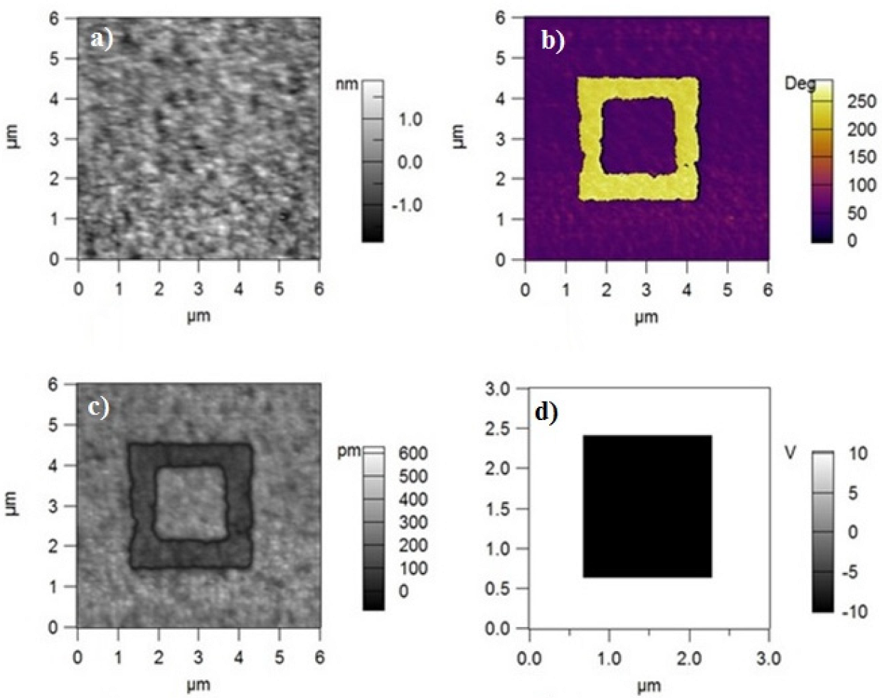
The topography of the BFO layer is presented in Figure 3a. One can see that the surface is flat, with a roughness below 1 nm, as indicated by the height bar on the right of the AFM image and by the root mean square (RMS) of approximately 0.7 nm. The very low roughness confirms the XRD results that no parasitic phases are present in the BFO layer such as, for example, Bi2O3 or γ-Fe2O3. These typically have rectangular shapes and different growth rate, appearing as protuberances embedded in the smoother BFO matrix and leading to a larger roughness than that of the present films [43,44]. The ferroelectric behavior is studied by applying a poling map as is represented in Figure 3d. The PFM phase and amplitude images, after applying the poling map, are presented in Figure 3b,c. The phase contrast in Figure 3b confirms the different orientations of polarization, as resulted from applying voltages of opposite polarities on the surface of the BFO thin film. Additionally, it can be observed that the surface outside of the poling area has the same orientation of the polarization as the surface poled with −10 V. Thus, it can be concluded that the as-deposited BFO thin films have a preferential upward polarization direction.

3.3. Ferroelectric Characterization and Extraction of the Pyroelectric Coefficient

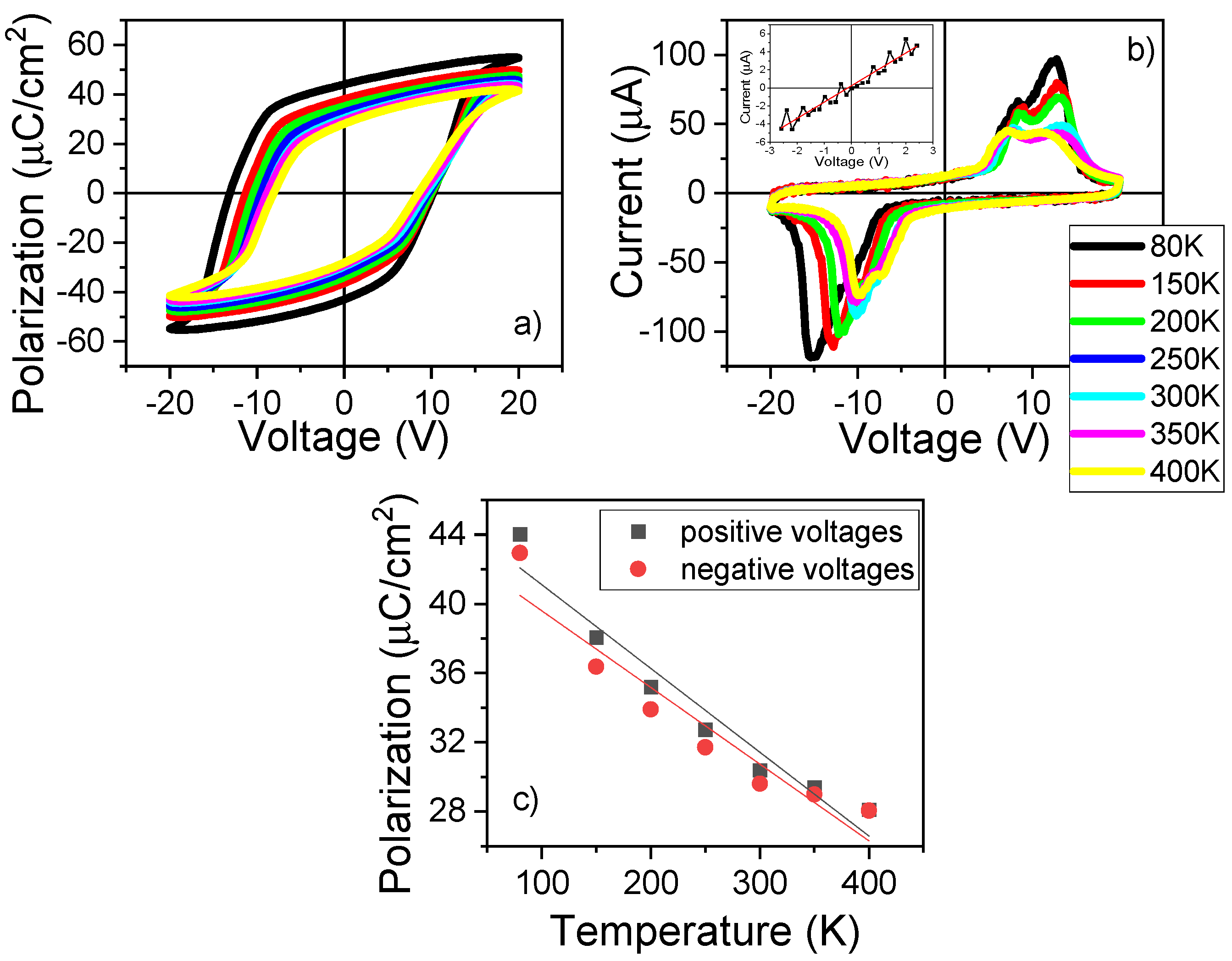
The polarization-voltage (Figure 4a) and current-voltage (Figure 4b) hysteresis loops are recorded between 80 K and 400 K. One has to mention that the polarization hysteresis loops shown in Figure 4a are, in fact, obtained by integrating the current hysteresis loops presented in Figure 4b. The coercive voltage extracted from polarization hysteresis loops varies with increasing temperature from 10 V to 8.6 V in the case of positive voltages and from −13 V to −8.2 V in the case of negative voltages. The coercive field at room temperature is 633 kV/cm. The remnant polarization has a variation from 44 to 28 µC/cm2 when temperature increases, as shown in Figure 4c. The variation is apparently linear for the investigated temperature range between 100 K and 400 K, which is in contradiction with the quadratic dependence predicted by thermodynamic theories [45]. However, there are also studies reporting linear dependence of polarization on temperature [46,47,48]. Considering these aspects, we have used to procedures to estimate the pyroelectric coefficient from the results presented in Figure 4c: (1) we have assumed a linear dependence and from the slope of this dependence we have estimated the pyroelectric coefficient as p = dP/dT; (2) we have used the adjacent values of remnant polarization and we have calculated the pyroelectric coefficient for every 50 K steps of temperature as p = ΔP/ΔT, then averaged the obtained values to estimate an average pyroelectric coefficient for the temperature range between 100 K and 400 K. At the end, we have averaged the values obtained for positive and negative remnant polarizations in both cases presented above. The obtained result is (4.6 ± 0.2) × 10−4 C/m2K. The uncertainty comes from the slope in the first case (the confidence Pearson’s factor is of 95% for negative values and 97% for positive ones), and from the slight temperature variation of the pyroelectric coefficient in the second case (the variation becomes significant near the phase transition [49] but it is not the case in the present study, as the phase transition in BFO is above1000 K [50]). The butterfly shape of the capacitance-voltage characteristics presented in Figure 5 confirms the ferroelectric behavior of the Au/SRO/BFO/SRO/STO structure. The value of the dielectric constant at 0 V has a small variation, from 66 to 71, when the temperature is increased from 80 K to 300 K.

3.4. Analysis of the Frequency Dependence of the Pyroelectric Signal

The evaluation of the pyroelectric coefficient from the temperature dependence of the remnant polarization extracted from polarization-voltage loops recorded at different temperatures is generally viewed as an indirect method [51]. Another more direct method is to record the frequency dependence of the pyroelectric signal generated by the sample under modulated IR illumination and estimate the pyroelectric coefficient from this dependence by using the following equation [37,52,53]:
S = ω η p A P i n c G T G e ( 1 + ω 2 τ T 2 ) 1 / 2 ( 1 + ω 2 τ e 2 ) 1 / 2
ω is the pulsation of the IR incident radiation on the pyroelectric element, ω = 2 π f , with f being the modulation frequency of the IR beam; P i n c is the power density of the incident IR radiation; η is the emissivity of the electrode exposed to IR radiation; p is the pyroelectric coefficient; A is the area of the top electrode; G T is the thermal conductance; G e is the electric conductance; τ T is the thermal time constant ( τ T = C T / G T , with G T being the thermal capacity of the pyroelectric element) and τ e   is the electrical time constant ( τ e = C e / G e , with C e being the capacitance of the pyroelectric element).
The estimation of the pyroelectric coefficient was performed using the model developed in reference [53] for a pyroelectric thin film deposited on a thick substrate. This theoretical model takes into account both the thickness of the BFO thin film and the substrate, denoted by w1 and w2. One has to mention that the bottom SRO electrode was neglected in the calculations, having a thickness much smaller compared to the substrate, and even with the BFO layer, and because its thermal properties are close to those of the STO substrate [54]. The thermal time constant involved in Equation (1) was calculated using the equation from reference [53], with the values given in Table 1:
τ T = w 2 g H [ c 2 d 2 + w 1 ( c 2 d 2 g H δ 1 + c 1 d 1 w 2 ) ]
where g H is the heat loss at the top surface estimated as g H = 4 σ T 0 3 , σ is the Stefan–Boltzmann constant 5.67 × 10⁻⁸ W/m2 K4, T 0 is the ambient temperature (298 K), d is the density, c the specific heat, and   δ the thermal conductivity. The subscripts 1 and 2 denotes the BFO layer and the STO substrate, respectively (see Table 1):
The thermal time constant of the structure was estimated to be approximatively τ T 232   s .
To estimate the electrical time constant, the capacitance at 1 kHz and zero volts applied on the sample was measured (60 pF), while the electrical conductance was estimated to about 1.8 ± 0.3 × 10⁻⁶ S from the slope of the current-voltage characteristic at voltages close to the origin, where the characteristic is almost linear, as shown in the inset of Figure 4b). The resulting value for τ e is of about 3.3 ± 0.3 × 10⁻⁵ s. It results that the condition ω 2 τ e 2 1 is fulfilled, while ω 2 τ T 2 1 . With these approximations, Equation (1) becomes:
S = η p A P i n c 2 g H G e τ T
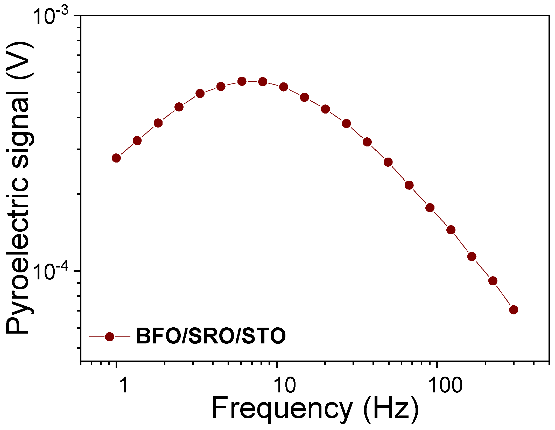
Equation (3) suggests that the pyroelectric signal should be constant for certain frequencies. This was verified experimentally by recording the dependence of the pyroelectric signal generated by the Au/SRO/BFO/SRO/STO structure as a function of the modulation frequency of the IR beam in the frequency range between 1 Hz and 300 Hz. The results are represented in Figure 6. The top electrode was covered with a layer of carbon ink as absorber for the IR radiation, ensuring an emissivity factor close to unity. This characteristic is typical for pyroelectric detectors, presenting a small plateau where the signal is almost constant (between about 5 Hz and 10 Hz), followed by a decrease at higher frequencies. Therefore, the pyroelectric signal measured at 8 Hz (0.57 mV) was introduced in Equation (3) and the pyroelectric coefficient was calculated, assuming η = 1 , an electrode area of 0.2·10−6 m2, and a power density of the incident IR radiation of 50 mW/mm2.
The obtained value for the pyroelectric coefficient is of about 2.8 ± 0.4·10−4 C/m2 K, which is of the same range of magnitude than the one estimated from the temperature dependence of the remnant polarization extracted from the hysteresis loops (see Figure 4c). The uncertainty is larger in this case due to emissivity, that can be not exactly unity, due to electrical conductance, and due to possible fluctuations of the optical power delivered by the laser diode (estimated to about 5%).
The values estimated in the present study for the pyroelectric coefficient of BFO are significantly larger than what was previously reported in the literature, the difference being up to one order of magnitude, as resulting from Table 2.
An important point to note is that the magnitude of the pyroelectric coefficient is not related to the absolute value of the remnant polarization but to the magnitude of the polarization variation when the sample is subjected to a temperature change. It is thus possible to obtain large values of the pyroelectric coefficient even when the value of the remnant polarization is slightly lower. A possible explanation for this enhanced pyroelectric coefficient can be related to the dispersion in the c/a ratio over the BFO volume, as observed from XRD studies. Local polarization is related to the local c/a ratio, thus a dispersion in polarization values may be also present in volume. The dispersion in polarization value can lead to complicated domain structure in the volume, with domain walls very sensitive to any polarization variation. This can lead to enhanced temperature response and pyroelectric coefficient, similar to the ones reported for epitaxial PZT layers [53,58,59].

4. Conclusions

BFO epitaxial thin films have been successfully deposited by PLD on STO (100) substrate. The investigated capacitor structures have top and bottom SRO electrodes. The electrical characterization reveals the presence of good ferroelectric properties on a wide temperature range, from 80 K to 400 K, with an important variation of the remnant polarization as the temperature is increased. The values of the pyroelectric coefficient estimated from the temperature dependence of the remnant polarization ((4.8 ± 0.2) × 10−4 C/m2 K) and from the frequency dependence of the pyroelectric signal ((2.8 ± 0.4) × 10−4 C/m2 K) are significantly larger than previous reports and are comparable to the values reported for lead-based ceramic materials and polycrystalline thin films [60,61,62,63] but still are one order of magnitude lower than in high-quality epitaxial PZT thin films [53]. Thus, it was demonstrated that BFO epitaxial structures could be good candidates for lead-free pyroelectric applications.

Author Contributions

Conceptualization, M.B. and C.C.; methodology, C.C., L.M.H. and G.A.B.; investigation M.B., I.P. (Iuliana Pasuk), L.T., B.N. and G.A.B.; writing—original draft preparation, M.B. and C.C.; writing—review and editing, G.A.B., C.C., I.P. (Ioana Pintilie) and L.P.; supervision I.P. (Ioana Pintilie) and L.P. All authors have read and agreed to the published version of the manuscript.

Funding

This work was supported by the Romanian Ministry of Research and Innovation in the framework of the POC-G 54/2016 MAT2IT (contract no. 1550/2018) and Core Program PN19-03 (con-tract no. 21 N/08.02.2019) projects.

Institutional Review Board Statement

Not applicable.

Informed Consent Statement

Not applicable.

Data Availability Statement

Not applicable.

Acknowledgments

The authors wish to thank Mihai Cioca and Gabriel Dobrescu due to their help related to experimental configuration for pyroelectric measurements.

Conflicts of Interest

The authors declare no conflict of interest.

References

  1. Lines, M.E.; Glass, A.M. Principles and Applications of Ferroelectrics and Related Materials; Oxford University Press: Oxford, UK, 2001; ISBN 978-0-19-850778-9. [Google Scholar]
  2. Pawade, V.B.; Salame, P.H.; Bhanvase, B.A. Multifunctional Nanostructured Metal Oxides for Energy Harvesting and Storage Devices; CRC Press: Boca Raton, FL, USA, 2020; ISBN 978-1-00-007320-1. [Google Scholar]
  3. Martin, L.W.; Rappe, A.M. Thin-Film Ferroelectric Materials and Their Applications. Nat. Rev. Mater. 2016, 2, 16087. [Google Scholar] [CrossRef] [Green Version]
  4. Fan, Z.; Wang, J.; Sullivan, M.B.; Huan, A.; Singh, D.J.; Ong, K.P. Structural Instability of Epitaxial (001) BiFeO3 Thin Films under Tensile Strain. Sci. Rep. 2014, 4, 4631. [Google Scholar] [CrossRef] [PubMed] [Green Version]
  5. Jaffe, B.; Cook, W.R.; Jaffe, H. Piezoelectric Ceramics; Cook, B.J.R., Jaffe, H., Eds.; Academic Press: Cambridge, MA, USA, 1971; ISBN 978-0-12-379550-2. [Google Scholar]
  6. Shrout, T.R.; Zhang, S.J. Lead-Free Piezoelectric Ceramics: Alternatives for PZT? J. Electroceram. 2007, 19, 113–126. [Google Scholar] [CrossRef]
  7. Damjanovic, D.; Klein, N.; Li, J.; Porokhonskyy, V. What Can Be Expected from Lead-Free Piezoelectric Materials? Funct. Mater. Lett. 2010, 3, 5–13. [Google Scholar] [CrossRef]
  8. Wang, J.; Neaton, J.B.; Zheng, H.; Nagarajan, V.; Ogale, S.B.; Liu, B.; Viehland, D.; Vaithyanathan, V.; Schlom, D.G.; Waghmare, U.V.; et al. Epitaxial BiFeO3 Multiferroic Thin Film Heterostructures. Science 2003, 299, 1719–1722. [Google Scholar] [CrossRef] [PubMed]
  9. Mukherjee, A.; Basu, S.; Manna, P.K.; Yusuf, S.M.; Pal, M. Giant Magnetodielectric and Enhanced Multiferroic Properties of Sm Doped Bismuth Ferrite Nanoparticles. J. Mater. Chem. C 2014, 2, 5885–5891. [Google Scholar] [CrossRef]
  10. Kuo, C.-Y.; Hu, Z.; Yang, J.C.; Liao, S.-C.; Huang, Y.L.; Vasudevan, R.K.; Okatan, M.B.; Jesse, S.; Kalinin, S.V.; Li, L.; et al. Single-Domain Multiferroic BiFeO3 Films. Nat. Comm. 2016, 7, 12712. [Google Scholar] [CrossRef] [PubMed]
  11. Lebeugle, D.; Colson, D.; Forget, A.; Viret, M. Very Large Spontaneous Electric Polarization in BiFeO3 Single Crystals at Room Temperature and Its Evolution under Cycling Fields. Appl. Phys. Lett. 2007, 91, 022907. [Google Scholar] [CrossRef] [Green Version]
  12. Pintilie, L.; Dragoi, C.; Chu, Y.H.; Martin, L.W.; Ramesh, R.; Alexe, M. Orientation-Dependent Potential Barriers in Case of Epitaxial Pt–BiFeO3–SrRuO3 Capacitors. Appl. Phys. Lett. 2009, 94, 232902. [Google Scholar] [CrossRef]
  13. Oikawa, T.; Aratani, M.; Funakubo, H.; Saito, K.; Mizuhira, M. Composition and Orientation Dependence of Electrical Properties of Epitaxial Pb(ZrxTi1−x)O3 Thin Films Grown Using Metalorganic Chemical Vapor Deposition. J. Appl. Phys. 2004, 95, 3111–3115. [Google Scholar] [CrossRef]
  14. Yang, N.; Hu, C.-Z.; Ren, Z.-Q.; Bao, S.-Y.; Tian, B.-B.; Yue, F.-Y.; Xiang, P.-H.; Zhong, N.; Duan, C.-G.; Chu, J.-H. Nonvolatile Negative Optoelectronic Memory Based on Ferroelectric Thin Films. ACS Appl. Electron. Mater. 2020, 2, 1035–1040. [Google Scholar] [CrossRef]
  15. Bhatnagar, A.; Roy Chaudhuri, A.; Heon Kim, Y.; Hesse, D.; Alexe, M. Role of Domain Walls in the Abnormal Photovoltaic Effect in BiFeO3. Nat. Commun. 2013, 4, 2835. [Google Scholar] [CrossRef] [Green Version]
  16. Gao, W.; Lv, J.; Lou, X. Large Electric-Field-Induced Strain and Enhanced Piezoelectric Constant in CuO-Modified BiFeO3-BaTiO3 Ceramics. J. Am. Ceram. Soc. 2018, 101, 3383–3392. [Google Scholar] [CrossRef]
  17. Zhang, J.X.; Xiang, B.; He, Q.; Seidel, J.; Zeches, R.J.; Yu, P.; Yang, S.Y.; Wang, C.H.; Chu, Y.-H.; Martin, L.W.; et al. Large Field-Induced Strains in a Lead-Free Piezoelectric Material. Nat. Nanotechnol. 2011, 6, 98–102. [Google Scholar] [CrossRef] [PubMed]
  18. Zhang, L.; Huang, Y.-L.; Velarde, G.; Ghosh, A.; Pandya, S.; Garcia, D.; Ramesh, R.; Martin, L.W. Enhanced Pyroelectric Properties of Bi1−xLaxFeO3 Thin Films. APL Mater. 2019, 7, 111111. [Google Scholar] [CrossRef] [Green Version]
  19. Yao, Y.; Ploss, B.; Mak, C.L.; Wong, K.H. Pyroelectric Properties of BiFeO3 Ceramics Prepared by a Modified Solid-State-Reaction Method. Appl. Phys. A 2010, 99, 211–216. [Google Scholar] [CrossRef]
  20. Yuan, G.L.; Or, S.W. Enhanced Piezoelectric and Pyroelectric Effects in Single-Phase Multiferroic Bi1−xNdxFeO3 (X = 0–0.15) Ceramics. Appl. Phys. Lett. 2006, 88, 062905. [Google Scholar] [CrossRef] [Green Version]
  21. Li, Y.W.; Sun, J.L.; Chen, J.; Meng, X.J.; Chu, J.H. Preparation and Characterization of BiFeO3 Thin Films Grown on LaNiO3-Coated SrTiO3 Substrate by Chemical Solution Deposition. J. Cryst. Growth 2005, 285, 595–599. [Google Scholar] [CrossRef]
  22. Yao, Y.; Tao, T.; Liang, B.; Mak, C.L.; Lu, S.G. Pyroelectric Properties and AC Impedance Study of Bismuth Ferrite (BiFeO3) Ceramics. Ceram. Int. 2019, 45, 1308–1313. [Google Scholar] [CrossRef]
  23. Shaldin, Y.V.; Matyjasik, S.; Bush, A.A. Pyroelectric Properties of Bismuth Ferrite in the Low-Temperature Range. Crystallogr. Rep. 2007, 52, 123–128. [Google Scholar] [CrossRef]
  24. Yao, Y.B.; Liu, W.C.; Mak, C.L. Pyroelectric Properties and Electrical Conductivity in Samarium Doped BiFeO3 Ceramics. J. Alloys Comp. 2012, 527, 157–162. [Google Scholar] [CrossRef]
  25. Ihlefeld, J.F.; Podraza, N.J.; Liu, Z.K.; Rai, R.C.; Xu, X.; Heeg, T.; Chen, Y.B.; Li, J.; Collins, R.W.; Musfeldt, J.L.; et al. Optical Band Gap of BiFeO3 Grown by Molecular-Beam Epitaxy. Appl. Phys. Lett. 2008, 92, 142908. [Google Scholar] [CrossRef] [Green Version]
  26. Kumari, S.; Ortega, N.; Kumar, A.; Scott, J.F.; Katiyar, R.S. Ferroelectric and Photovoltaic Properties of Transition Metal Doped Pb(Zr0.14Ti0.56Ni0.30)O3−δ Thin Films. AIP Adv. 2014, 4, 037101. [Google Scholar] [CrossRef] [Green Version]
  27. Eason, R. Pulsed Laser Deposition of Thin Films: Applications-Led Growth of Functional Materials; John Wiley & Sons: Hoboken, NJ, USA, 2007. [Google Scholar]
  28. Chen, Z.H.; Damodaran, A.R.; Xu, R.; Lee, S.; Martin, L.W. Effect of “Symmetry Mismatch” on the Domain Structure of Rhombohedral BiFeO3 Thin Films. Appl. Phys. Lett. 2014, 104, 182908. [Google Scholar] [CrossRef] [Green Version]
  29. Kim, D.M.; Eom, C.B.; Nagarajan, V.; Ouyang, J.; Ramesh, R.; Vaithyanathan, V.; Schlom, D.G. Thickness Dependence of Structural and Piezoelectric Properties of Epitaxial Pb(Zr0.52Ti0.48)O3 Films on Si and SrTiO3 Substrates. Appl. Phys. Lett. 2006, 88, 142904. [Google Scholar] [CrossRef]
  30. Chirila, C.; Boni, G.A.; Filip, L.D.; Husanu, M.; Neatu, S.; Istrate, C.M.; Le Rhun, G.; Vilquin, B.; Trupina, L.; Pasuk, I.; et al. Effect of Strain and Stoichiometry on the Ferroelectric and Pyroelectric Properties of the Epitaxial Pb(Zr0.2Ti0.8)O3 Films Deposited on Si Wafers. Mater. Sci. Eng. B 2021, 266, 115042. [Google Scholar] [CrossRef]
  31. Chirila, C.; Boni, A.G.; Pasuk, I.; Negrea, R.; Trupina, L.; Rhun, G.L.; Yin, S.; Vilquin, B.; Pintilie, I.; Pintilie, L. Comparison between the Ferroelectric/Electric Properties of the PbZr0.52Ti0.48O3 Films Grown on Si (100) and on STO (100) Substrates. J. Mater. Sci. 2015, 50, 3883–3894. [Google Scholar] [CrossRef]
  32. Holcomb, M.; Ramesh, R. Controlling magnetism with multiferroics. Mater. Today 2007, 10, 16–223. [Google Scholar] [CrossRef]
  33. Ohnishi, T.; Shibuya, K.; Lippmaa, M.; Kobayashi, D.; Kumigashira, H.; Oshima, M.; Koinuma, H. Preparation of Thermally Stable TiO2-Terminated SrTiO3(100) Substrate Surfaces. Appl. Phys. Lett. 2004, 85, 272–274. [Google Scholar] [CrossRef]
  34. Koster, G.; Kropman, B.L.; Rijnders, G.J.H.M.; Blank, D.H.A.; Rogalla, H. Quasi-Ideal Strontium Titanate Crystal Surfaces through Formation of Strontium Hydroxide. Appl. Phys. Lett. 1998, 73, 2920–2922. [Google Scholar] [CrossRef] [Green Version]
  35. Jiang, Z.-Z.; Guan, Z.; Yang, N.; Xiang, P.-H.; Qi, R.-J.; Huang, R.; Yang, P.-X.; Zhong, N.; Duan, C.-G. Epitaxial Growth of BiFeO3 Films on SrRuO3/SrTiO3. Mater. Charact. 2017, 131, 217–223. [Google Scholar] [CrossRef]
  36. You, L.; Chua, N.T.; Yao, K.; Chen, L.; Wang, J. Influence of oxygen pressure on the ferroelectric properties of epitaxial BiFeO3 thin films by pulsed laser deposition. Phys. Rev. B 2009, 80, 024105. [Google Scholar] [CrossRef]
  37. Pintilie, L.; Iuga, A.; Stancu, V.; Botea, M. Estimation of the Pyroelectric Coefficient for Ceramic Pb(Zr,Ti)O3 Samples: Comparison of the Results Obtained by Two Easy to Implement Methods. Infrared Phys. Techn. 2020, 106, 103269. [Google Scholar] [CrossRef]
  38. Achenbach, G.D.; James, W.J.; Gerson, R. Preparation of Single-Phase Polycrystalline BiFeO3. J. Amer. Ceram. Soc. 1967, 50, 437. [Google Scholar] [CrossRef]
  39. Yang, Y.; Schlepütz, C.M.; Adamo, C.; Schlom, D.G.; Clarke, R. Untilting BiFeO3: The Influence of Substrate Boundary Conditions in Ultra-Thin BiFeO3 on SrTiO3. APL Mater. 2013, 1, 052102. [Google Scholar] [CrossRef] [Green Version]
  40. Xu, G.; Hiraka, H.; Shirane, G.; Li, J.; Wang, J.; Viehland, D. Low Symmetry Phase in (001) BiFeO3 Epitaxial Constrained Thin Films. Appl. Phys. Lett. 2005, 86, 182905. [Google Scholar] [CrossRef] [Green Version]
  41. Christen, H.M.; Nam, J.H.; Kim, H.S.; Hatt, A.J.; Spaldin, N.A. Stress-Induced R−MA−MC−T Symmetry Changes in BiFeO3. Phys. Rev. B 2011, 83, 144107. [Google Scholar] [CrossRef] [Green Version]
  42. Sando, D.; Barthélémy, A.; Bibes, M. BiFeO3 Epitaxial Thin Films and Devices: Past, Present and Future. J. Phys. Condens. Matter 2014, 26, 473201. [Google Scholar] [CrossRef]
  43. Lim, S.H.; Murakami, M.; Sarney, W.L.; Ren, S.Q.; Varatharajan, A.; Nagarajan, V.; Fujino, S.; Wuttig, M.; Takeuchi, I.; Salamanca-Riba, L.G. The Effects of Multiphase Formation on Strain Relaxation and Magnetization in Multiferroic BiFeO3 Thin Films. Adv. Funct. Mater. 2007, 17, 2594–2599. [Google Scholar] [CrossRef]
  44. Béa, H.; Bibes, M.; Barthélémy, A.; Bouzehouane, K.; Jacquet, E.; Khodan, A.; Contour, J.-P.; Fusil, S.; Wyczisk, F.; Forget, A.; et al. Influence of Parasitic Phases on the Properties of BiFeO3 Epitaxial Thin Films. Appl. Phys. Lett. 2005, 87, 072508. [Google Scholar] [CrossRef] [Green Version]
  45. Yurtseven, H.; Kiraci, A. Temperature dependence of the polarization and the dielectric constant near the paraelectric-ferroelectric transitions in BaTiO3. J. Mol. Model. 2013, 19, 3925–3930. [Google Scholar] [CrossRef] [PubMed]
  46. Phillpot, S.R.; Gopalan, V. Coupled displacive and order–disorder dynamics in LiNbO3 by molecular-dynamics simulation. Appl. Phys. Lett. 2004, 84, 1916–1919. [Google Scholar] [CrossRef] [Green Version]
  47. Chaib, H.; Toumanari, A.; Khatib, D.; Kinase, W. Theoretical study of temperature dependence of spontaneous polarization, optical properties and free and clamped linear electrooptic coefficients of BaTiO3 in the tetragonal phase. Ferroelectrics 1999, 234, 61–80. [Google Scholar] [CrossRef]
  48. Chen, Z.; Song, L.; Zhao, H.; Zhang, Y.; Cao, W. Temperature- and electric field-dependence of polarization hysteresis for a [001]c poled PMN-PT single crystal. J. Asian Ceram. Soc. 2022, 10, 203–214. [Google Scholar] [CrossRef]
  49. Glass, A.M. Dielectric, Thermal, and Pyroelectric Properties of Ferroelectric LiTaO3. Phys. Rev. 1968, 172, 564–571. [Google Scholar] [CrossRef]
  50. Arnold, D.C.; Knight, K.S.; Morrison, F.D.; Lightfoot, P. Ferroelectric-Paraelectric Transition in BiFeO3: Crystal Structure of the Orthorhombic β Phase. Phys. Rev. Lett. 2009, 102, 027602. [Google Scholar] [CrossRef] [PubMed] [Green Version]
  51. Lubomirsky, I.; Stafsudd, O. Invited Review Article: Practical Guide for Pyroelectric Measurements. Rev. Sci. Instrum. 2012, 83, 051101. [Google Scholar] [CrossRef] [PubMed]
  52. Whatmore, R.W. Pyroelectric Devices and Materials. Rep. Prog. Phys. 1986, 49, 1335–1386. [Google Scholar] [CrossRef]
  53. Botea, M.; Iuga, A.; Pintilie, L. Giant Pyroelectric Coefficient Determined from the Frequency Dependence of the Pyroelectric Signal Generated by Epitaxial Pb(Zr0.2Ti0.8)O3 Layers Grown on Single Crystal SrTiO3 Substrates. Appl. Phys. Lett. 2013, 103, 232902. [Google Scholar] [CrossRef]
  54. Yamanaka, S.; Maekawa, T.; Muta, H.; Matsuda, T.; Kobayashi, S.; Kurosaki, K. Thermophysical properties of SrHfO3 and SrRuO3. J Solid State Chem. 2004, 177, 3484–3489. [Google Scholar] [CrossRef]
  55. Elements, A. Bismuth Ferrite. Available online: https://www.americanelements.com/bismuth-ferrite-12010-42-3 (accessed on 11 February 2022).
  56. Klyndyuk, A.I.; Khort, A.A. Thermophysical Properties of BiFeO3, Bi0.91Nd0.09FeO3, and BiFe0.91Mn0.09O3 Multiferroics at High Temperatures. Phys. Solid State 2016, 58, 1285–1288. [Google Scholar] [CrossRef]
  57. Zhang, C.; Huberman, S.C.; Ning, S.; Pelliciari, J.; Duncan, R.A.; Liao, B.; Ojha, S.; Freeland, J.W.; Nelson, K.A.; Comin, R.; et al. Thermal Conductivity in Self-Assembled CoFe2O4/BiFeO3 Vertical Nanocomposite Films. Appl. Phys. Lett. 2018, 113, 223105. [Google Scholar] [CrossRef]
  58. Karthik, J.; Agar, J.C.; Damodaran, A.R.; Martin, L.W. Effect of 90 Domain Walls and Thermal Expansion Mismatch on the Pyroelectric Properties of Epitaxial PbZr0.2Ti0.8O3 Thin Films. Phys. Rev. Lett. 2012, 109, 257602. [Google Scholar] [CrossRef] [PubMed] [Green Version]
  59. Karthik, J.; Martin, L.W. Pyroelectric Properties of Polydomain Epitaxial PbZr1-XTixO3 Thin Films. Phys. Rev. B 2011, 84, 024102. [Google Scholar] [CrossRef] [Green Version]
  60. De Cicco, G.; Morten, B.; Dalmonego, D.; Prudenziati, M. Pyroelectricity of PZT-Based Thick-Films. Sens. Actuat. A Phys. 1999, 76, 409–415. [Google Scholar] [CrossRef]
  61. Bowen, C.R.; Taylor, J.; LeBoulbar, E.; Zabek, D.; Chauhan, A.; Vaish, R. Pyroelectric Materials and Devices for Energy Harvesting Applications. Energy Environ. Sci. 2014, 7, 3836–3856. [Google Scholar] [CrossRef] [Green Version]
  62. He, H.; Lu, X.; Hanc, E.; Chen, C.; Zhang, H.; Lu, L. Advances in Lead-Free Pyroelectric Materials: A Comprehensive Review. J. Mater. Chem. C 2020, 8, 1494–1516. [Google Scholar] [CrossRef]
  63. Stancu, V.; Amarande, L.; Botea, M.; Iuga, A.; Leonat, L.N.; Tomulescu, A.G.; Cioangher, M.; Balescu, L.M.; Pintilie, L. Comparison between Dielectric and Pyroelectric Properties of PZFNT and BST Type Ceramics. Process. Appl. Ceram. 2019, 13, 269–276. [Google Scholar] [CrossRef]
Figure 1. Results obtained by XRD measurements: (a,b) two representative regions of the 2θ-ω scan; (c) azimuth scans on the {103} inclined crystal planes of the films and substrate; (d) out-of-plane rocking curve obtained on 002 BFO; (e) reciprocal space mapping in the vicinity of the 103 STO node. Pseudocubic indexing for BFO and SRO.
Electronicmat 03 00015 g001
Figure 2. The surface topography of STO substrate after thermal and chemical treatment (a) with line profile (b) by AFM. The line profile after processing the image by plane leveling procedure (c).
Electronicmat 03 00015 g002
Figure 3. (a) The topography of the BFO thin film; (b) the phase obtained during a PFM scan after poling; (c) the amplitude obtained during a PFM scan after poling; (d) the poling map.
Electronicmat 03 00015 g003
Figure 4. (a) The polarization-voltage characteristics recorded at different temperatures; (b) the current-voltage characteristics recorded at different temperatures; (c) the variation of the absolute value of the remnant polarization as a function of temperature (black square markers and lines are for the positive values, red circle markers and line are for the negative values). The inset in Figure 4b presents the variation of the current at low voltages and low frequency, around origin (see Section 2). The current-voltage dependence around origin is approximately linear (the Pearson’s confidence factor is around 97%) and was used to extract the electrical conductance.
Electronicmat 03 00015 g004
Figure 5. The capacitance-voltage characteristics were recorded at different temperatures.
Electronicmat 03 00015 g005
Figure 6. The dependence of pyroelectric signal as a function of modulation frequency.
Electronicmat 03 00015 g006
Table 1. The physical quantities that are used to calculate the thermal time constant, using Equation (2).
LayerThickness
(w)
Density
(kg/m3)
Specific
Heat
(J/kg⋅K)
Thermal
Conductivity
(W/m⋅K)
BFO w 1 = 150 nm d 1 = 8220 [55] c 1 = 385 [56] δ 1 = 1.32 [57]
STO w 2 = 500 µm d 2 = 5120 [53] c 2 = 544 [53] δ 2 = 11.2 [53]
Table 2. Comparative values for the pyroelectric coefficient of BFO (present study and previous reports in the literature).
SamplePyroelectric Coefficient (10−4 C/m2 K) Reference
Au/SRO/BFO/SRO/STO2.8–4.8Present Study
BFO ceramics0.9Ref. [19]
Bi1−𝑥Nd𝑥FeO3 (𝑥 = 0–0.15) ceramics0.3–0.4Ref. [20]
BiFeO3 thin films on SrTiO3 substrate by chemical solution deposition0.14Ref. [21]
BFO ceramics0.71Ref. [22]
BFO single crystals1.2Ref. [23]
Sm-doped BFO ceramics0.93–1.37Ref. [24]
Publisher’s Note: MDPI stays neutral with regard to jurisdictional claims in published maps and institutional affiliations.