Article

Analytical Vibration Solutions of Sandwich Lévy Plates with Viscoelastic Layers at Low and High Frequencies

by
Yichi Zhang
and
Bingen Yang
*
Department of Aerospace and Mechanical Engineering, University of Southern California, Los Angeles, CA 90089, USA
*
Author to whom correspondence should be addressed.
Appl. Mech. 2025, 6(3), 49; https://doi.org/10.3390/applmech6030049
Submission received: 29 April 2025 / Revised: 23 June 2025 / Accepted: 28 June 2025 / Published: 1 July 2025

Abstract

The sandwich plates in consideration are structures composed of a number of Lévy plate components laminated with viscoelastic layers, and they are seen in broad engineering applications. In vibration analysis of a sandwich plate, conventional analytical methods are limited due to the complexity of the geometric and material properties of the structure, and consequently, numerical methods are commonly used. In this paper, an innovative analytical method is proposed for vibration analysis of sandwich Lévy plates having different configurations of viscoelastic layers and using various models of viscoelastic materials. The focus of the investigation is on the determination of closed-form frequency response at any given frequencies. In the development, an s-domain state-space formulation is established by the Distributed Transfer Function Method (DTFM). With this formulation, closed-form analytical solutions of the frequency response problem of sandwich plates are obtained, without the need for spatial discretization. As one unique feature, the DTFM-based approach has consistent formulas and unified solution procedures by which analytical solutions at both low and high frequencies are obtained. The accuracy, efficiency, and versatility of the proposed analytical method are demonstrated in three numerical examples, where the DTFM-based analysis is compared with the finite element method and certain existing analytical solutions.

1. Introduction

Sandwich plates are found in numerous applications in aerospace, mechanical, and civil engineering [1,2]. A typical sandwich plate consists of two parallel plates (known as plate components) that are laminated by an elastic or viscoelastic layer. In broad applications, sandwich plate structures with multiple parallel plate components laminated by viscous layers are considered to fulfill more practical interests [3]. In these plate structures, viscoelastic damping is used for passive vibration control [4]. The vibration analysis of multi-layer sandwich plates with viscoelastic layers is important to the design and optimization of complex structures.
The current study is concerned with a new analytical approach for vibration analysis of sandwich Lévy plates, which is useful for computation at low and high frequencies. Sandwich Lévy plates are composed of rectangular plate components with two opposite edges being simply supported and the other edges arbitrarily supported. Through the years, Lévy plates and Lévy solutions have found broad engineering applications. Some examples are given as follows. The Lévy solution was applied to an axially moving viscoelastic plate in free vibration analysis [5]. The free vibrations of orthotropic plates and functionally graded plates were studied using Lévy solutions [6,7]. In bending analyses, Lévy solutions were employed for functionally graded sandwich plates [8] and Mindlin microplates [9]. With a state-space method, the bending of laminated plates was analyzed using a Lévy solution [10]. A Lévy-type solution was proposed for the buckling analysis of composite sandwich plates [11]. Moreover, the Lévy solution has been applied to shells [12].
Vibration problems of plate structures are investigated in different frequency regions, low-frequency, medium-frequency (mid-frequency), and high-frequency regions, which are defined based on the comparison of the dimensions of a plate structure with the wavelength of interest [13]. The finite element analysis (FEA) is a popular and versatile tool for vibration solutions [14], and it has been applied to the low-frequency vibration analysis of sandwich structures [15,16] and vibration problems of composite structures [17]. In the FEA, a large number of plate elements in spatial discretization is necessary, and to maintain adequate accuracy of the computed results, the number of elements increases significantly when the vibration frequency becomes high. In general, the FEA is not suitable for mid- and high-frequency vibration problems of plate structures.
In contrast, the Statistical Energy Analysis (SEA) is an approach to the solution of high-frequency vibro-acoustic problems [18], and it has been applied to engineering composite structures [19,20]. In the SEA, each plate component of a sandwich structure is treated as one “element”. The governing equations of the structure are obtained according to the energy balance in the entire structure. Since the SEA can only provide the “energy level” of each “element”, no local information on the plate components can be obtained. While the traditional SEA is only suitable in the high-frequency region, a hybrid SEA-FEA method was proposed for the mid-frequency vibration analysis for multi-layer sandwich composites with a viscoelastic layer [21]. The Wave Finite Element Method (WFE) is another approach that has been applied to high-frequency vibration analysis of sandwich structures with viscoelastic layers [22,23]. In both the SEA-FEA method and the WFE method, a large number of finite elements are required to maintain the accuracy of numerical solutions.
In addition to numerical methods, several analytical and semi-analytical solutions have been obtained in vibration analysis of certain sandwich plates. For instance, Hamilton’s principle and the series expansion were employed to investigate the free vibration and damping characteristics of multi-layer sandwich structures with viscoelastic layers [24]. A semi-analytical higher-order mixed theory was utilized to evaluate the natural frequencies of simply supported sandwich structures [25]. An exact explicit solution based on the Kirchhoff–Love assumption was derived to capture the behavior of three-layer plates [26]. In addition, an analytical solution based on the Navier solution was used for the analysis of simply supported composite plate structures [27].
The above-mentioned analytical and semi-analytical solutions were all derived by series approximations based on the Navier solution, and as such, they are only valid for plates that are simply supported at all edges. These methods are not directly applicable to sandwich Lévy plates. As pointed out in Ref. [27], in a high-frequency vibration analysis by a series solution, hundreds of thousands of terms are required to obtain converged results. In the literature, the existing analytical solutions for sandwich Lévy plates are limited only to low-frequency vibration problems, and they are not directly applicable to vibration problems at high frequencies.
The recent decade has seen continued research interest in sandwich plates [28,29]. A comprehensive review of vibration analyses of general composite laminated structures during 2015–2024 is conducted in reference [30].
In summary of the literature survey, there are several issues regarding vibration analysis of sandwich plates with viscoelastic layers. First, different methods are required for vibration solutions in different frequency regions. Indeed, none of the existing methods is valid for vibration analysis at both low and high frequencies. Second, most available methods for mid- and high-frequency vibration analysis cannot provide the local information in the structure under consideration, such as the bending moment and shear force of a plate component at a particular location. Third, to the best knowledge of the authors, no analytical solutions for sandwich Lévy plates in mid- and high-frequency vibrations are available. This investigation is motivated by the need for a new analytical solution method for sandwich Lévy plates at both low and high frequencies.
In this paper, with the focus on closed-form analytical solutions of frequency response, a new analytical method for sandwich Lévy plates with thin viscoelastic layers is proposed. This method is devised based on the Distributed Transfer Function Method (DTFM) [31,32]. The DTFM has been applied to mid- and high-frequency vibration analysis of beam structures [33] and modeling and analysis of double-beam structures [34]. The current effort can be viewed as an extension of the DTFM to a class of two-dimensional composite continua, namely, sandwich Lévy plates.
As shall be seen, the proposed DTFM can systematically deliver closed-form analytical solutions to the frequency response problem of sandwich Lévy plates with various configurations (layouts) of viscoelastic layers. The proposed method has two notable features. First, the new method is applicable to computation at both low and high frequencies, with a consistent formulation and solution procedure. Second, at high frequencies, the new method can conveniently provide detailed local information of a sandwich plate, such as bending moment and shear force at any location. These useful features are lacking in conventional methods. Although the focus of the current effort is to develop a unified method that is valid for computation at both low and high frequencies, mid- and high-frequency vibration analysis of sandwich plates in detail is beyond the scope of this paper.
The remainder of this paper is organized as follows. Section 2 states the problem of mathematical modeling and vibration analysis of the sandwich Lévy plate structures in consideration, with four representative configurations of viscoelastic layers. The governing equations of motion for the plate structures are presented in Section 3. In Section 4, a spatial state-space formulation in the s-domain is established for modeling and analysis of the plate structures. In Section 5, various models of viscoelastic materials are presented. In Section 6, with the preparation in the previous sections, the closed-form solutions of the eigenvalue problem and frequency response problem of the sandwich Lévy plate structures are determined. The proposed analytical method is illustrated in three numerical examples in Section 7, where the accuracy and efficiency of the method in computing frequency response is validated with the existing analytical solutions and FEM simulations, and the utility of the method at higher frequencies is demonstrated. The conclusions from this investigation are summarized in Section 8.

2. Problem Statement

This paper is concerned with mathematical modeling and vibration analysis of Lévy plate structures with viscoelastic layers. A Lévy plate is a rectangular plate with two opposite edges simply supported and the other two edges having arbitrary boundary conditions. A sandwich Lévy plate is a structure composed of a number of parallel Lévy plate components laminated with viscoelastic layers. Figure 1 shows four representative configurations of the Lévy plate structures considered in this study. The first configuration is a single plate lying on a viscoelastic foundation, as shown in Figure 1a. The second configuration is given in Figure 1b, where two plates are bound by a viscoelastic layer over the entire plate region. The third configuration is illustrated in Figure 1c, where two plates are coupled by a viscoelastic layer that is partially distributed. And, the fourth configuration is shown in Figure 1d, where three plates are laminated by two viscoelastic layers that are partially distributed and dislocated. In this work, a Lévy plate is described according to the Kirchhoff–Love plate theory, in which the in-plane deformation of the plate is ignored and various models of viscoelastic layers are considered. The viscoelastic layers in consideration are assumed to be sufficiently thin such that their shear deformation can be neglected. It is also assumed that the layers are tightly bonded to plate components, and no longitudinal deformation is considered in the plates.
The objective of this effort is to develop a unified analytical method for vibration analysis of the above-mentioned sandwich Lévy plates, at both low and high frequencies. To this end, a DTFM-based approach is proposed to determine closed-form analytical solutions for the problems of free vibration and frequency response of this type of plate structure.

3. Governing Equations

In this section, the equations of motion and boundary conditions of the Lévy plate structures with the four configurations shown in Figure 1 are presented. Assume that all the plate components have the same length a (in the x direction) and the same width b (in the y direction) and that they are simply supported at the edges x = 0 and a . For simplicity of presentation, the viscoelastic layers are described by the Kelvin–Voigt model, which can be viewed as a pair of distributed springs and a viscous damper. Other models of viscoelastic layers shall be introduced later in Section 5.

3.1. Single Plate on a Viscoelastic Foundation

Consider the single Lévy plate on a viscoelastic foundation in Figure 1a. Denote the transverse displacement of the plate by w ( x , y , t ) . The vibration of the plate is governed by the partial differential equation [35] as follows:
2 ρ h 2 w x , y , t t 2 + D 4 w x , y , t + k f w x , y , t + c f w ˙ x , y , t = q x , y , t
for 0 < x < a and 0 < y < b , where 4 is the biharmonic operator given by 4 = 4 x 4 + 2 4 x 2 y 2 + 4 y 4 , 2 h is the thickness of the plate, ρ is the volume density of the plate, and q x , y , t is a transverse external force. Furthermore, D is the bending stiffness of the plate given by D = 2 h 3 E 3 ( 1 ν 2 ) , with E and ν being the Young’s modulus and Poisson’s ratio of the plate material. k f and c f are the constant coefficients describing the elasticity and viscosity of the foundation by the Kelvin–Voigt model. As mentioned previously, the plate is simply supported at the edges x = 0 and a with the following boundary conditions:
at   x = 0 :   w = 0 at   x = a :   2 w x 2 = 0
The boundary conditions at other edges can be arbitrarily assigned. For instance, for a plate with a clamped edge at y = 0 and a free edge at y = b , the corresponding boundary conditions are
a t   y = 0 : w = 0 , w x = 0 a t   y = b : D 2 w x 2 + ν 2 w y 2 = 0 , D 3 w x 3 + 2 ν 3 w x y 2 = 0

3.2. Double-Plate Structure with a Fully Distributed Viscoelastic Layer

Consider the double-plate structure in Figure 1b, where two parallel Lévy plates are interconnected by a uniformly distributed viscoelastic layer. Denote the transverse displacements of plates 1 and 2 by w 1 x , y , t and w 2 x , y , t , respectively. With the coefficients k l and c l of the viscoelastic layer, the vibration of the plate structure is governed by the two coupled partial differential equations as follows:
2 ρ 1 h 1 2 w 1 x , y , t t 2 + D 1 4 w 1 x , y , t + k l w 1 x , y , t w 2 x , y , t + c l w ˙ 1 x , y , t w ˙ 2 x , y , t = q 1 x , y , t 2 ρ 2 h 2 2 w 2 x , y , t t 2 + D 2 4 w 2 x , y , t + k l w 2 x , y , t w 1 x , y , t + c l w ˙ 2 x , y , t w ˙ 1 x , y , t = q 2 x , y , t
for 0 < x < a and 0 < y < b , where 2 h i , ρ i , E i , ν i , and D i are the parameters of the ith plate, which are defined in Section 3.1, and q i x , y , t is an external force applied to the ith plate. The simply supported boundary conditions of the plates at x = 0 and a are given by
at   x = 0 and   a w i = 0 ,   2 w i x 2 = 0 ,   for   i = 1 , 2
The boundary conditions of the plates at y = 0 and b can be arbitrarily assigned, as demonstrated in Equation (3). The two plates may have different boundary conditions at y = 0 and b .

3.3. Double-Plate Structure with a Partially Distributed Viscoelastic Layer

Consider a sandwich plate structure that is similar to the one in Figure 1c. The structure has two parallel Lévy plates that are coupled by a partially distributed viscoelastic layer of coefficients k l and c l , which is defined in the subregion 0 < x < a and 0 < y < b 1 , with b 1 < b . A side view of the plate structure in the y z plane is given in Figure 2a, showing that the plates are not coupled in the region 0 < x < a and b 1 < y < b . Denote the transverse displacements of plates 1 and 2 by w 1 x , y , t and w 2 x , y , t , respectively. The equations of motion of the plate structure are given by
2 ρ 1 h 1 2 w 1 x , y , t t 2 + D 1 4 w 1 x , y , t + y k l w 1 x , y , t w 2 x , y , t + y c l w ˙ 1 x , y , t w ˙ 2 x , y , t = q 1 x , y , t 2 ρ 2 h 2 2 w 2 x , y , t t 2 + D 2 4 w 2 x , y , t + ( y ) k l w 2 x , y , t w 1 x , y , t + ( y ) c l w ˙ 2 x , y , t w ˙ 1 x , y , t = q 2 x , y , t
where
y = H y H y b 1
with H y being the unit step function, which is zero for y < 0 and one for y 0 . The parameters in Equation (6) are the same as those in Equation (4). The boundary conditions of the plates can be specified by following Section 3.1 and Section 3.2.

3.4. Three-Plate Structure with Dislocated Viscoelastic Layers

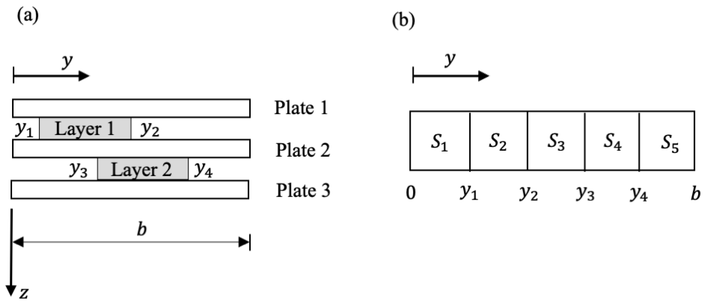
Consider a three-plate structure that is similar to the one shown in Figure 1d. The structure has three parallel Lévy plates that are coupled by two partially distributed and dislocated viscoelastic layers. A side view of the plate structure in the y z plane is shown in Figure 3a, where viscoelastic layer 1 of coefficients k 1 and c 1 is defined in the subregion 0 < x < a and y 1 < y < y 2 and layer 2 of coefficients k 2 and c 2 is defined in the subregion 0 < x < a and y 3 < y < y 4 . Let the displacement of the ith plate be w i x , y , t . The vibration of the plate structure is described by the following three coupled partial differential equations:
2 ρ 1 h 1 2 w 1 x , y , t t 2 + D 1 4 w 1 x , y , t + 12 y k 1 w 1 x , y , t w 2 x , y , t + 12 y c 1 w ˙ 1 x , y , t w ˙ 2 x , y , t = q 1 x , y , t 2 ρ 2 h 2 2 w 2 x , y , t t 2 + D 2 4 w 2 x , y , t + 12 y k 1 w 2 x , y , t w 1 x , y , t + 12 y c 1 w ˙ 2 x , y , t w ˙ 1 x , y , t + 23 y k 2 w 2 x , y , t w 3 x , y , t + 23 y c 2 w ˙ 2 x , y , t w ˙ 3 x , y , t = q 2 x , y , t 2 ρ 3 h 3 2 w 3 x , y , t t 2 + D 3 4 w 3 x , y , t + 23 y k 2 w 3 x , y , t w 3 x , y , t + 23 y c 2 w ˙ 3 x , y , t w ˙ 3 x , y , t = q 3 x , y , t
with
12 y = H y y 1 H y y 2 ,   23 y = H y y 3 H y y 4
where H y is the unit step function. The definition of the parameters in Equation (8) and the specification of the boundary conditions of the plates follow Section 3.2. The three plates may have different boundary conditions at y = 0 and b .

4. State-Space Formulation in the s-Domain

In this work, a unified method for the determination of the closed-form analytical solutions of the eigenvalue problem and frequency response of sandwich Lévy plate structures is developed by the Distributed Transfer Function Method (DTFM) [31]. To this end, a state-space formulation in the Laplace transform domain (s-domain) for each of the plate configurations in Section 3 is derived. Because the eigenvalue and frequency response problems are considered, zero initial disturbances of the plate(s) are assumed in the subsequent derivations.

4.1. Formulation for Single Plate on a Viscoelastic Foundation

In this subsection, the DTFM is illustrated on the single plate as described in Section 3.1. Taking the Laplace transform in Equation (1) with respect to time gives the governing equation in the s -domain
2 ρ h s 2 w ¯ x , y , s + D 4 w ¯ x , y , s + G f s w ¯ x , y , s = q ¯ x , y , s
where s is the Laplace transform parameter and the overbar stands for Laplace transformation, and
G f s = k f + c f s
which is a transfer function of the viscoelastic foundation from the plate displacement to the resultant of the spring and damping forces. The Lévy solution to Equation (10) is of the series form
w ¯ x , y , s = m = 1 Y ¯ m y , s sin α m x
where α m = m π a and Y ¯ m y , s are unknown functions to be determined. Note that the series satisfies the simply supported boundary conditions specified in Equation (2). The external force can also be expanded in the Fourier series
q ¯ x , y , s = m = 1 q ¯ m y , s sin α m x
where q ¯ m y , s   are known functions. Substituting Equation (12) into Equation (10) and using Equation (13) yields an infinite number of independent (decoupled) differential equations about Y ¯ m y , s :
2 ρ h s 2 Y ¯ m y , s + D α m 4 Y ¯ m y , s 2 α m 2 d 2 Y ¯ m y , s d y 2 + d 4 Y ¯ m y , s d y 4 + G f s Y ¯ m y , s = q ¯ m y , s
for 0 < y < b and m = 1 , 2 , 3 , .
For Equation (14), with a specific integer m , define a state vector by
η ^ m y , s = Y ¯ m y , s d Y ¯ m y , s d y d 2 Y ¯ m y , s d y 2 d 3 Y ¯ m y , s d y 3 T
According to the DTFM [22], Equation (14) is cast into an equivalent state equation below
d d y η ^ m y , s = F ^ m s η ^ m y , s + p ^ m y , s , f o r   0 < y < b
where
F ^ m s = 0 1 0 0 0 0 1 0 0 0 0 1 2 ρ h s 2 G f ( s ) D α m 4 0 2 α m 2 0 p ^ m y , s = 0 0 0 q ¯ m y , s D T
The boundary conditions of the Lévy plate at the edges y = 0 and b are specified as follows:
Simply supported edge at y * = 0 or b
Y ¯ m y , s = γ ~ 1 , m ( s ) ,   D d 2 Y ¯ m y , s d y 2 = γ ~ 2 , m ( s )
Clamped edge at y * = 0 or b
Y ¯ m y , s = γ ~ 3 , m ( s ) ,     d Y ¯ m y , s d y = γ ~ 4 , m ( s )
Free edge at y * = 0 or b
D ν α m 2 Y ¯ m y , s + d 2 Y ¯ m y , s d y 2 = γ ~ 5 , m ( s ) D ν 2 α m 2 d Y ¯ m y , s d y + d 3 Y ¯ m y , s d y 3 = γ ~ 6 , m ( s )
In the previous equations, γ ~ r , m s and r = 1 ,   2 , , 6 , represent boundary disturbances, which are a specified force/moment or a prescribed displacement/rotation. With the state vector η ^ m y , s , the boundary conditions in Equations (18)–(20) can be cast into the matrix form as follows:
M m s η ^ m 0 , s + N m s η ^ m b , s = γ ^ m s
where M m s and N m s are four-by-four boundary matrices and γ ^ m s is a vector consisting of the boundary excitations as described by γ ~ r , m s . As an example, for a Lévy plate that is clamped at y = 0 and free at y = b , the boundary matrices and boundary excitation vector are given by
M m s = 1 0 0 0 0 1 0 0 0 0 0 0 0 0 0 0 ,     N m s = 0 0 0 0 0 0 0 0 D ν α m 2 0 D 0 0 D ν 2 α m 2 0 D γ ^ m s = γ ~ 3 , m ( s ) γ ~ 4 , m ( s ) γ ~ 5 , m ( s ) γ ~ 6 , m ( s ) T
Equations (16) and (21) give an s-domain state-space formulation for the Lévy plate over a viscoelastic foundation.

4.2. Formulation for Double-Plate Structure with a Fully Distributed Viscoelastic Layer

For the sandwich plate structure in Section 3.2, the Laplace transform in Equation (4) gives
2 ρ 1 h 1 s 2 w ¯ 1 x , y , s + D 1 4 w ¯ 1 x , y , s + G l s w ¯ 1 x , y , s w ¯ 2 x , y , s = q ¯ 1 x , y , s 2 ρ 2 h 2 s 2 w ¯ 2 x , y , s + D 2 4 w ¯ 2 x , y , s + G l s w ¯ 2 x , y , s w ¯ 1 x , y , s = q ¯ 2 x , y , s
where G l s is the transfer function of the viscoelasticity of the sandwich layer given by
G l s = k l + c l s
The s-domain displacements of the plates, which are the Lévy solutions to Equation (23), are written as
w ¯ i x , y , t = m = 1 Y ¯ i , m y , t sin α m x , f o r   i = 1   a n d   2
with α m = m π a . Note that in Equation (25), the simply supported boundary conditions (5) are automatically satisfied. Also, expand the external forces by Fourier series
q ¯ i x , y , s = m = 1 q ¯ i , m y , s sin α m x
where q ¯ i , m y , s are known functions. Substituting Equation (25) into Equation (23) and using Equation (26) yields an infinite number of coupled differential equations as follows:
2 ρ 1 h 1 s 2 Y ¯ 1 , m y , s + D 1 α m 4 Y ¯ 1 , m y , s 2 α m 2 d 2 Y ¯ 1 , m y , s d y 2 + 4 Y ¯ 1 , m y , s y 4 + G l s Y ¯ 1 , m y , s Y ¯ 2 , m y , s = q ¯ 1 , m y , s 2 ρ 2 h 2 s 2 Y ¯ 2 , m y , s + D 2 α m 4 Y ¯ 2 , m y , s 2 α m 2 d 2 Y ¯ 2 , m y , s d y 2 + 4 Y ¯ 2 , m y , s y 4 + G l s Y ¯ 2 , m y , s Y ¯ 1 , m y , s = q ¯ 2 , m y , s
for 0 < y < b and m = 1 , 2 , 3 , .
For Equation (27) with a specific m , define a state vector for each plate as follows:
η ^ i , m y , s = Y ¯ i , m y , s d Y ¯ i , m y , s d y d 2 Y ¯ i , m y , s d y 2 d 3 Y ¯ i , m y , s d y 3 T
for i = 1 and 2 . By following Section 4.1, Equation (27) is converted to the matrix form
d d y η ^ 1 , m y , s = F ^ 1 , m s η ^ 1 , m y , s + C 1 s η ^ 2 , m y , s + p ^ 1 , m y , s d d y η ^ 2 , m y , s = F ^ 2 , m s η ^ 2 , m y , s + C 2 s η ^ 1 , m y , s + p ^ 2 , m y , s
where
F ^ i , m s = 0 1 0 0 0 0 1 0 0 0 0 1 2 ρ i h i s 2 G l ( s ) D i α m 4 0 2 α m 2 0   p ^ i , m y , s = 0 0 0 q ¯ i , m y , s D i , C i s = G l ( s ) D i   0 0 0 0 0 0 0 0 0 0 0 0 1 0 0 0
for i = 1 and 2 . Furthermore, by defining the global state vector for the plate structure
η ^ g , m y , s = η ^ 1 , m y , s η ^ 2 , m y , s C 8
the equations given in Equation (29) are assembled into a global state equation as follows:
d d y η ^ g , m y , s = F ^ g , m s η ^ g , m y , s + p ^ g , m y , s
for 0 < y < b , where
F ^ g , m s = F ^ 1 , m s C 1 ( s ) C 2 ( s ) F ^ 2 , m s C 8 × 8   ,   p ^ g , m y , s = p ^ 1 , m y , s p ^ 2 , m y , s C 8 × 1
The boundary conditions for the plates at y = 0 and b , by following Section 4.1, are obtained as follows:
  • For plate 1
    M 1 , m s η ^ 1 , m 0 , s + N 1 , m s η ^ 1 , m b , s = γ ^ 1 , m s
  • For plate 2
    M 2 , m s η ^ 2 , m 0 , s + N 2 , m s η ^ 2 , m b , s = γ ^ 2 , m s
With Equation (31), the boundary conditions of the plate structure are written in the global form:
M g , m s η ^ g , m 0 , s + N g , m s η ^ g , m b , s = γ ^ g , m s
where
M g , m s = M 1 , m s 0 4 × 4 0 4 × 4 M 2 , m s ,     N g , m s = N 1 , m s 0 4 × 4 0 4 × 4 N 2 , m s γ ^ g , m s = γ ^ 1 , m s γ ^ 2 , m s
with 0 4 × 4 being the 4-by-4 zero matrix.
Equations (32) and (36) present an s -domain state-space formulation for the structure. Note that these equations have the same format as given in Equations (16) and (21). Because of this, the solution procedure for a single plate and that for a double-plate structure are essentially the same.

4.3. Formulation for Double-Plate Structure with a Partially Distributed Viscoelastic Layer

The sandwich plate structure in Section 3.3 can be viewed as a stepped distributed system with two subsystems. The s -domain displacements of the plate components can also be expressed by the series given in Equation (25). In Figure 2b and in terms of the Lévy solutions, the subsystems are defined as follows:
(i) Subsystem S 1 , which is formed by two segments of the plates that are coupled by the viscoelastic layer in the subregion 0 < x < a and 0 < y < b 1 . This subsystem is in the case discussed in Section 4.2. Thus, the subsystem can be described by Equation (27), for 0 < y < b 1 .
(ii) Subsystem S 2 , which is formed by two segments of the plates that are not coupled in the subregion 0 < x < a and b 1 < y < b . According to Equation (6), the subsystem is described by Equation (27) with the viscoelastic layer removed:
2 ρ 1 h 1 s 2 Y ¯ 1 , m y , s + D 1 α m 4 Y ¯ 1 , m y , s 2 α m 2 d 2 Y ¯ 1 , m y , s d y 2 + 4 Y ¯ 1 , m y , s y 4 = q ¯ 1 , m y , s 2 ρ 2 h 2 s 2 Y ¯ 2 , m y , s + D 2 α m 4 Y ¯ 2 , m y , s 2 α m 2 d 2 Y ¯ 2 , m y , s d y 2 + 4 Y ¯ 2 , m y , s y 4 = q ¯ 2 , m y , s
for b 1 < y < b and m = 1 , 2 , 3 , .
The two subsystems are interconnected along the line 0 < x < a and y = b 1 . By the Lévy solutions, the following matching conditions on displacement continuity and force balance are imposed:
Y ¯ i , m b 1 , s = Y ¯ i , m b 1 + , s   d Y ¯ i , m b 1 , s d y = d Y ¯ i , m b 1 + , s d y M ¯ i , m b 1 , s = M ¯ i , m b 1 + , s + τ ¯ c , m ( s ) V ¯ i , m b 1 , s = V ¯ i , m b 1 + , s + q ¯ c , m ( s )
where i = 1 ,   2 and m = 1 ,   2 ,   3 ,…. In the previous equations, M ¯ i , m and V ¯ i , m are the bending moment and effective force along the line y = b 1 , which are obtained by the Kirchhoff–Love plate theory, and τ ¯ c , m ( s ) and q ¯ c , m ( s ) are related to external loads applied to the line y = b 1 .
Define the state vectors for the subsystems as follows:
η ^ S 1 , m y , s = η ^ 1 , m y , s η ^ 2 , m y , s ,             f o r   S 1 :   0 y b 1 η ^ S 2 , m y , s = η ^ 1 , m y , s η ^ 2 , m y , s ,             f o r   S 2 :   b 1 y b
where η ^ i , m y , s are the same as defined in Equation (28). The state-space formulation for the plate structure is obtained using the augmented DTFM, as described in [31,32]. To this end, introduce a nondimensional local coordinate z for the subsystems: for S 1 , z = y / b 1 , and for S 2 , z = y / b b 1 . The range of z is between 0 and 1 for each of the subsystems. With Equations (27) and (38), the state equations of the subsystems are derived in z as follows:
d d z η ^ S 1 , m z , s = F ^ S 1 , m s η ^ S 1 , m z , s + p ^ S 1 , m z , s d d z η ^ S 2 , m z , s = F ^ S 2 , m s η ^ S 2 , m z , s + p ^ S 2 , m z , s
for 0 < z < 1 , where the scaled state vectors are given by η ^ S 1 , m z , s = η ^ S 1 , m y = b 1 z , s and η ^ S 2 , m z , s = η ^ S 2 , m y = b b 1 z , s . Note that the state vectors of the subsystems in the state equations are presented in the nondimensional coordinate z . This provides an advantage in the assembly of the global equations for a multi-plate structure, as shall be seen shortly. The boundary conditions of the subsystems, by following Section 4.1 and Section 4.2, are obtained in z as follows:
M S 1 , m s η ^ S 1 , m 0 , s + N S 2 , m s η ^ S 2 , m 1 , s = γ ^ b , m ( s )
Moreover, the matching conditions in Equation (39) can be cast into the following form (also in terms of z ):
A m s η ^ S 1 , m 1 , s + B m s η ^ S 2 , m 0 , s = γ ^ c , m ( s )
where A m s and B m s are 8-by-8 matrices.
Finally, by introducing the global state vector
η ^ g , m z , s = η ^ S 1 , m z , s η ^ S 2 , m z , s
where 0 z 1 , a global state-space formulation for the double-plate structure with a partially distributed viscoelastic layer is obtained as follows:
  • State equation
d d z η ^ g , m z , s = F ^ g , m s η ^ g , m z , s + p ^ g , m z , s ,             f o r   0 < z < 1
  • Boundary condition
M g , m s η ^ g , m 0 , s + N g , m s η ^ g , m 1 , s = γ ^ g , m s
where
F ^ g , m s = F ^ S 1 , m s 0 8 × 8 0 8 × 8 F ^ S 2 , m s ,             p ^ g , m z , s = p ^ S 1 , m z , s p ^ S 2 , m z , s M g , m s = M S 1 , m s 0 8 × 8 0 8 × 8 B m s ,             N g , m s = 0 8 × 8 N S 2 , m s A m s 0 8 × 8 γ ^ g , m s = γ ^ b , m ( s ) γ ^ c , m ( s )    
with 0 8 × 8 being the 8-by-8 zero matrix. Equations (45) and (46) contain 16 × 16 matrices.

4.4. Formulation for Three-Plate Structure with Dislocated Viscoelastic Layers

Consider the plate structure with two dislocated viscoelastic layers in Section 4.3 and Figure 3a. Without a loss of generality, let the layers be located such that 0 < y 1 < y 3 < y 2 < y 4 < b . The plate structure can be viewed as a stepped system with five subsystems, S 1 , S 2 , … S 5 , as shown in Figure 3b, where each subsystem consists of the segments of the three plates divided by the points y 1 , y 2 , y 3 , and y 4 . The subsystems are defined as follows:
S 1 : in the subregion 0   y y 1 , without any viscoelastic layer;
S 2 : in the subregion y 1   y y 3 , with plates 1 and 2 coupled by layer 1;
S 3 : in the subregion y 3   y y 2 , with all three plates coupled by the two layers;
S 4 : in the subregion y 2   y y 4 , with plates 2 and 3 coupled by layer 2;
S 5 : in the subregion y 4   y b , without any viscoelastic layer.
For these subsystems, the state equations, boundary conditions, and matching conditions at points y 1 , y 2 , y 3 , and y 4 can be established by following Section 4.3. Furthermore, in using the augmented DTFM [22,23], set a nondimensional local coordinate z for the subsystems as follows: for S 1 , z = y / y 1 ; for S 2 , z = y / y 3 y 1 ; for S 3 , z = y / y 2 y 3 ; for S 4 , z = y / y 4 y 2 ; and for S 5 , z = y / b y 4 . In each subsystem, 0 z 1 , which makes it convenient to assemble a global state equation for the sandwich plate structure. It follows that a state-space formulation with the same format as Equations (42) and (43) can be established, although the state vectors and matrices in these equations have different dimensions and elements.

4.5. Discussion

The state-space formulations for the four representative configurations in Figure 1 have been developed. While sandwich structures with up to three plate components are investigated, the methodology presented herein is readily applicable to structures with an arbitrary number of Lévy plate components. For a multi-plate structure with viscoelastic layers fully distributed in the entire region ( 0 < x < a , 0 < y < b ), the state-space formulation given by Equations (32) and (36), in terms of the original coordinate y, can be directly used. For a multi-plate structure with partially distributed viscoelastic layers, the state-space formulation given by Equations (45) and (46), in terms of the nondimensional coordinate z, is applicable. With these formulations, closed-form analytical solutions of free vibration and frequency response of sandwich Lévy plates can be conveniently obtained by following Section 6 and Section 7.

5. Models of Viscoelastic Layers

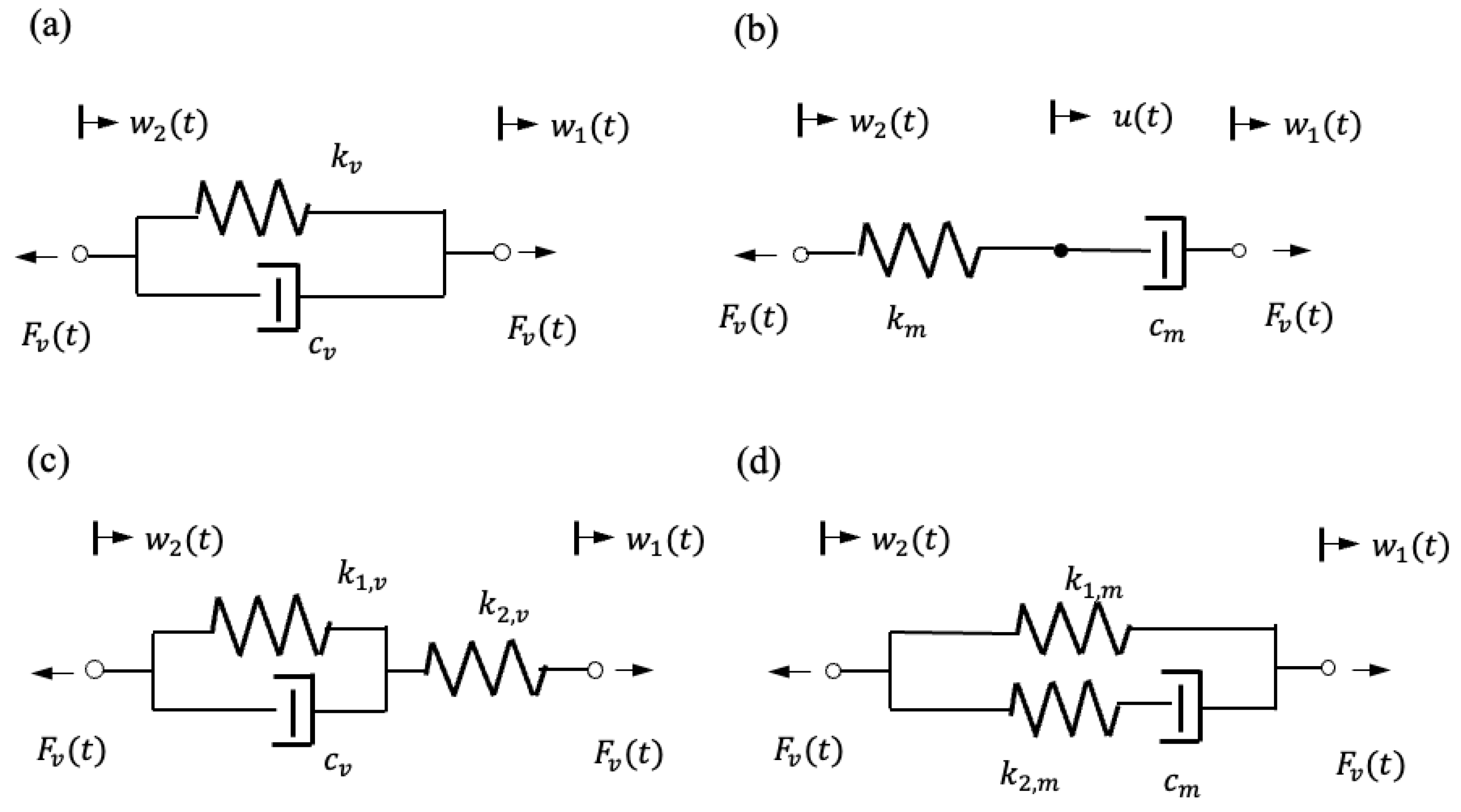
In the previous sections, for simplicity of presentation, only the Kelvin–Voigt model is considered. As a matter of fact, various models of viscoelastic materials can be implemented in the state-space formulations, as given in Section 4. This can be easily performed by replacing G f s in Equation (11) or G l s in Equation (24) with a transfer function of the viscoelastic material in consideration. The transfer function of a viscoelastic material is also known as the dynamic modulus or complex modulus of the material. In this section, the Kelvin–Voigt model, the Maxwell model, and standard linear solid models [36,37] are reviewed, and the relevant transfer functions are presented. These models are shown in Figure 4, where w 1 t   and w 2 t are the displacements of a one-dimensional fiber of the material at two ends and F v t is the internal force at the ends of the fiber.

5.1. Kelvin–Voigt Model

Figure 4a shows a schematic of the Kelvin–Voigt model of viscoelastic material, which can be viewed as the parallel connection of a spring of coefficient k v and a dashpot of coefficient c v . With the end displacements w 1 t   and w 2 t , the internal force F v t generated by the Kelvin–Voigt model is expressed as
F v t = k v w 1 t w 2 t + c v w ˙ 1 t w ˙ 2 t
Taking the Laplace transform in Equation (45) with zero initial disturbances gives
F ¯ v s = G v s w ¯ 1 x , s w ¯ 2 x , s
where the transfer function of the Kelvin–Voigt model is
G v s = k v + c v s
which has been used in Section 4. The Kelvin–Voigt model can be used to describe the creep deformation of solid material.

5.2. Maxwell Model

Shown in Figure 4b is a schematic of the Maxwell model of viscoelastic material, which can be viewed as the serial connection of a spring of coefficient k m and a dashpot of coefficient c m . With the end displacements w 1 t   and w 2 t , the internal forces generated by the Maxwell model can be described by
F v t = F k t = F c t F k t = k m u t w 2 t F c t = c m w ˙ 1 t u ˙ t
where F k t and F c t are the forces inserted by the spring and dashpot and u t   is the displacement at the point where the spring and dashpot are interconnected. By the Laplace transform in Equation (51) and after some manipulations, we arrive at
F ¯ v s = G m s w ¯ 1 s w ¯ 2 s
where the transfer function of the Maxwell model is
G m s = k m c m s k m + c m s
The Maxwell model can be used to describe relaxation in the soft solid material.

5.3. Standard Linear Solid Models

Neither the Kelvin–Voigt model nor the Maxwell model can describe the creep and relaxation at the same time. To predict the material properties more precisely, standard linear solid models have been introduced [37]. Figure 4c,d show two standard linear solid models: the Kelvin–Voigt representation of the standard linear solid model and the Maxwell representation of the standard linear solid model. It can be shown that for the Kelvin–Voigt representation
F ¯ v s = G S L S , K V s w ¯ 1 s w ¯ 2 s
the transfer function is given by
G S L S , K V s = k 2 , v k 1 , v + c v s k 1 , v + k 2 , v + c v s
The Maxwell representation is given by
F ¯ v s = G S L S , M s w ¯ 1 s w ¯ 2 s
with the transfer function given by
G S L S , M s = k 1 , m k 2 , m + k 1 , m + k 2 , m c m s k 2 , m + c m s
In addition to the above models, more complicated models of viscoelastic materials can be considered. A general form of the dynamic modulus (transfer function) of viscoelastic materials is given by G v e s = N ( s ) D ( s ) , with N s and D s being polynomials of s [36]. One special feature of the DTFM-based approach is that the transfer functions of various material models can be easily implemented in the state-space formulations, as given in Section 4. Consequently, vibration analysis of sandwich plate structures with different viscoelastic materials can be conveniently carried out, as shown in Section 6.

6. Vibration Analysis by the DTFM

With the s-domain state-space formulations given in Section 4, vibration analyses of sandwich Lévy plates with viscoelastic layers can be performed. In this section, the closed-form solutions of the eigenvalue problem and frequency response problem of sandwich Lévy plates are determined by the DTFM. As mentioned previously, plate structures with fully distributed viscoelastic layers and those with partially distributed viscoelastic layers are considered separately.

6.1. Plate Structures with Fully Distributed Viscoelastic Layers

For a Lévy plate structure with fully distributed viscoelastic layer(s), its state-space formulation is described by Equations (32) and (36), which are copied as follows:
  • State equation
d d y η ^ g , m y , s = F ^ g , m s η ^ g , m y , s + p ^ g , m y , s ,             0 < y < b
  • Boundary condition
M g , m s η ^ g , m 0 , s + N g , m s η ^ g , m b , s = γ ^ g , m s
for m = 1 ,   2 , ….
The eigenvalue problem of the structure is described by [31]
M g , m s + N g , m s e F ^ g , m s b a = 0
where e F ^ g , m s b is the exponential of the matrix F ^ g , m s b , s is an eigenvalue, and a is a nonzero constant vector to be determined. The characteristic equations of the structure are
m ( s ) d e t M g , m s + N g , m s e F ^ g , m s b = 0 ,             m = 1,2 , 3 ,
whose roots are the eigenvalues of the structure. For a root s = s , the associated eigenfunction is expressed as
ψ ^ g , m y = e F ^ g , m s y a * ,             0 y b
where a * is a nonzero solution in Equation (54) with s = s .
For an undamped sandwich plate, its natural frequencies can be obtained in Equation (61) with s = j ω , where j = 1 . The characteristic Equation (61) can be solved by standard root-finding algorithms, including the bisection method. Thus, the natural frequencies of the plate structure can be conveniently computed in any frequency region. On the other hand, for a damped sandwich plate, a root locus method as given in Reference [38] can be used to determine the eigensolutions of the structure.
In frequency response analysis of a plate structure, Equations (58) and (59) are solved by the DTFM [31], which yields
η ^ g , m y , s = 0 b G ^ g , m y , ξ ,   s p ^ g , m ξ , s d ξ + H ^ g , m y , s γ ^ g , m s
for 0 < y < b and m = 1 ,   2 ,   3 ,…. In the previous equation, G ^ g , m y , ξ , s and H ^ g , m y , s are the distributed transfer functions of the structure for a particular integer m , and they are given in the exact and closed form by
G ^ g , m y , ξ , s = H ^ g , m y , s M g , m s e F ^ g , m s ξ ,   ξ y H ^ g , m y , s N g , m s e F ^ g , m s ( b ξ ) ,   ξ > y H ^ g , m y , s = e F ^ g , m s y M g , m s + N g , m s e F ^ g , m s b 1
for y ,   ξ 0 , b . In Equation (63), the s -domain displacements w ¯ i x , y , t of the plates can be obtained by the series (25). Thus, the steady-state response (frequency response) of the structure subject to a harmonic force of excitation frequency Ω is given by Equation (63) with s = j Ω , where j = 1 . Note that by Equation (64), the exact closed-form frequency response functions G ^ g , m y , ξ , j Ω and H ^ g , m y , j Ω are obtained.
Once the global state vectors η ^ g , m y , s are obtained, the values of Y ¯ i , m y , s and its derivatives can be obtained in Equation (28). The frequency response of the transverse displacement, slope, moment, and shear force of the plate structure at any point can be computed according to the plate theory [27]. For instance, the bending moment M i , y y and shear force Q i , y of the ith plate are given by
M ¯ i , y y x , y , s = m = 1 D ν m π a 2 Y ¯ i , m y , s + 2 Y ¯ i , m y , s y 2 sin m π x a Q ¯ i ,   y x , y , s = m = 1 D m π a 2 Y ¯ i , m y , s y + 3 Y ¯ i , m y , s y 3 sin m π x a
In addition, the widely used energy variables in mid- and high-frequency vibration analysis can also be computed from state variables.

6.2. Plate Structures with Partially Distributed Viscoelastic Layers

For a Lévy plate structure with partially distributed viscoelastic layers, its state-space formulation is described by Equations (45) and (46) using the augmented DTFM [31,32] and in terms of the nondimensional coordinate z , 0 z 1 . The format of the vibration solutions in this case is similar to that in the case of fully distributed viscoelastic layers, as presented in Section 6.1. Thus, the eigenequation of the structure is
M g , m s + N g , m s e F ^ g , m s a = 0
The eigensolutions can be obtained by following Section 6.1. Furthermore, the solution of Equations (42) and (43) is given by
η ^ g , m z , s = 0 1 G ^ g , m z , ξ ,   s p ^ g , m ξ , s d ξ + H ^ g , m z , s γ ^ g , m s
where the distributed transfer functions are given in exact and closed form:
G ^ g , m z , ξ , s = H ^ g , m z , s M g , m s e F ^ g , m s ξ ,   ξ z H ^ g , m z , s N g , m s e F ^ g , m s ( 1 ξ ) ,   ξ > z H ^ g , m z , s = e F ^ g , m s z M g , m s + N g , m s e F ^ g , m s 1
for z ,   ξ 0,1 . In Equations (67) and (68), the frequency response solutions of the plate structure can be obtained in closed form.

6.3. Discussion

In the above DTFM-based analyses, no spatial discretization has been made. For an eigenvalue problem, exact solutions can be obtained using Equations (60) and (66), at both low and high frequencies. For a frequency response problem, the only approximation made in computation is the truncation of the infinite series, such as those given in Equations (25) and (65). Nevertheless, closed-form analytical solutions are obtained. When the excitation frequency Ω increases, the number of terms used in the truncated series also increases to maintain the accuracy of the computed results. Nevertheless, in mid- and high-frequency vibration analysis, the number of unknowns with the DTFM is much less than that with any other analytical method and significantly less than the number of elements required in a finite element analysis. The numerical efficiency of the proposed method is demonstrated in the following section.

7. Numerical Examples

The DTFM-based analytical approach, as presented in the previous sections, is illustrated on three numerical examples: a double-plate structure with a fully distributed viscoelastic layer (Section 7.1), a double-plate structure with a partially distributed viscoelastic layer (Section 7.2), and a three-layer sandwich plate with partially distributed and dislocated viscoelastic layers (Section 7.3). In these examples, the proposed method is validated with the existing analytical solutions and the finite element analysis, and the accuracy, efficiency, and versatility of the new method in computing frequency responses at high frequencies are demonstrated. The finite element codes were created by the authors. For convenience of discussion, simply supported, clamped, and free edges of a plate are denoted by letters S, C, and F, respectively, and the boundary conditions of a plate are assigned in the counterclockwise direction, starting with the edge at x = 0. For instance, SCSF indicates a plate with the boundary conditions as specified by Equations (2) and (3).

7.1. Example 1: A Double-Plate Structure with a Fully Connected Viscoelastic Layer

This example is a benchmark for the validation of the accuracy, efficiency, and consistency of the DTFM in vibration analysis of the sandwich plate, from low to high frequencies. Shown in Figure 1b is a double-plate structure with a fully connected viscoelastic layer described by the Kelvin–Voigt model. As stated before, for each plate component in the sandwich structure, two edges at x = 0 and x = a are simply supported, and the other two edges at y = 0 and y = b can be arbitrary. Consider two identical plate components. For numerical simulation, the parameters of the double-plate structure are chosen as follows:
a = 1   m ,   b = 1.5   m ,   2 h = 0.025   m ,   E = 200   G P a
ν = 0.3 ,   ρ = 7800   k g / m 3 ,   k v = 2.5 × 10 6   N / m ,   c v = 2.5 × 10 5   N s / m
Consider a pointwise sinusoidal force, F f t = F 0 sin 2 π f t , acting on the upper plate at point x = 0.5   m and y = 0.9   m , where f is the excitation frequency in Hertz. Let the unity force amplitude be used, F 0 = 1   N .
First, for validation purposes, the natural frequencies of the plate structure laminated by an elastic layer ( c v = 0 ) are computed by the DTFM, as presented in Section 6, and the FEM, with 50, 200, and 3200 elements. (Viscoelastic layers shall be considered later on in a frequency response problem.) Listed in Table 1 are the first five and some higher-mode natural frequencies of the plate structure with all edges being simply supported (SSSS). Also, the natural frequencies of the plate structure with SCSC boundary conditions are presented in Table 2. It is shown in the tables that as the number of elements increases, the FEM predictions converge to the DTFM results, which are the exact natural frequencies of the plate structure. For the higher-mode natural frequencies, the FEM requires more elements, such as 3200 elements.
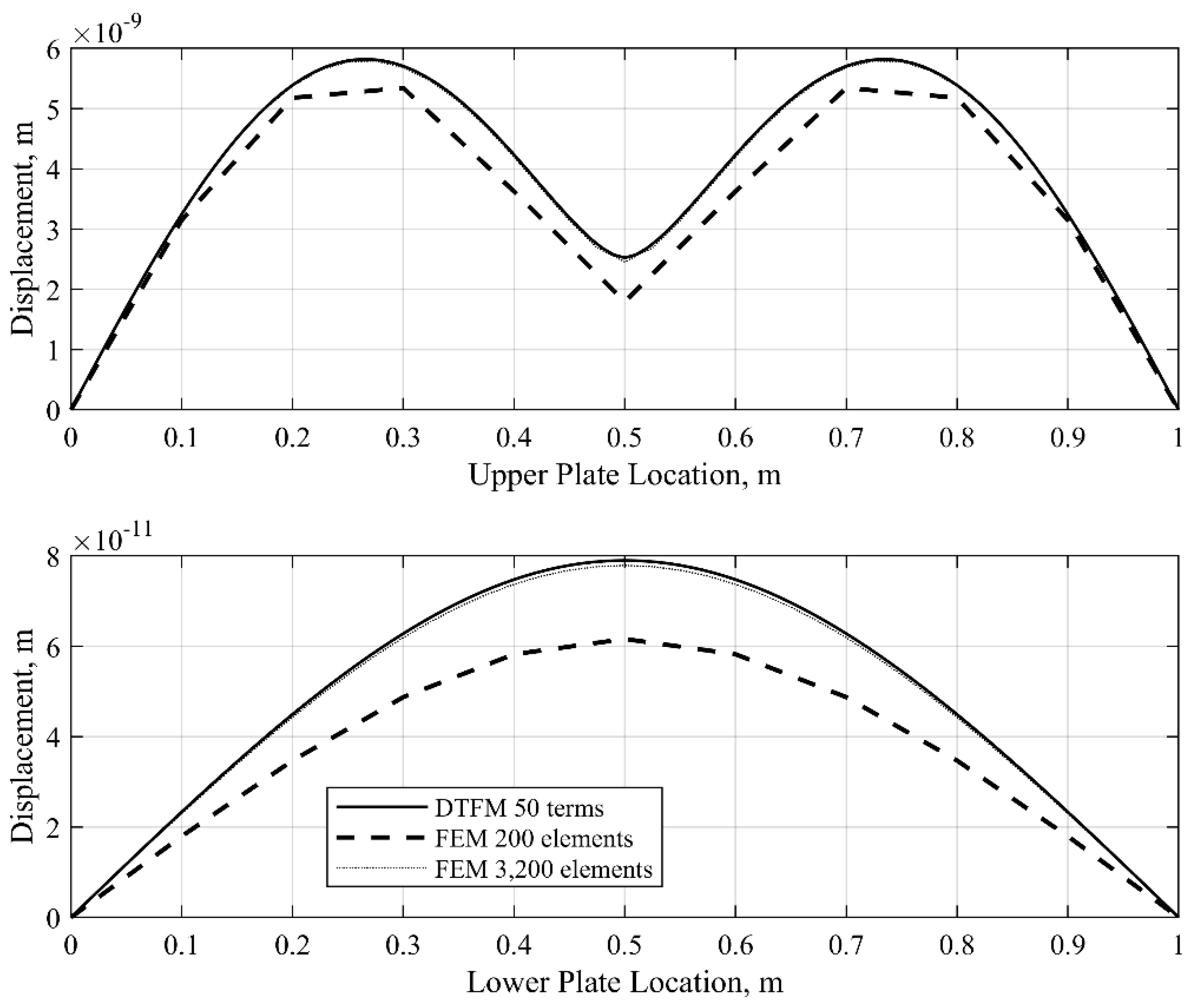
Second, the frequency response of the plate structure with the previously described viscoelastic layer and SFSF boundary conditions is computed. Let the excitation frequency be given by f = 200   H z . The frequency response is obtained by the DTFM as shown in Equation (63) and the FEM with 200 elements and 3200 elements for comparison. In the DFTM-based analysis, the first 50 terms (m = 50) in Equation (25) are taken. The spatial distribution of the transverse displacement magnitudes along the line y = 0.9   m on the upper plate and the line y = 0.6   m are plotted in Figure 5. As shown in this figure, the transverse displacement obtained by the FEM with 3200 elements is in good agreement with that of the DTFM with 50 terms. Note that the transverse displacement magnitudes obtained by the 200-element FEM cannot match the results of the DTFM and the 3200-element FEM. For the 3200-element FEM, the dimensions of the stiffness and mass matrices are 9922 × 9922 , indicating significant efforts required in computation. On the other hand, the DTFM just needs 50 terms, with 8 × 8 global state matrices involved in computation. The numerical results here validate the accuracy and efficiency of the DTFM-based analysis.
Next, the frequency response of the plate structure with SFSF boundary conditions is computed from low to mid frequencies, that is, from 100   H z to 1000   H z . The upper bound of the frequency region, 1000   H z , lies between the 34 th and 35 th natural frequencies of the undamped sandwich plate ( c v = 0 ). Figure 6 shows the transverse displacement results at point x = 0.5 m and y = 0.9 m on the upper plate and point x = 0.5 m and y = 0.6 m on the lower plate of the elastically connected two-layer sandwich plate (SFSF boundary condition) by the 50-term DTFM, the 200-element FEM, and the 3200-element FEM. The results obtained by the 50-term DTFM and those by the 3200-element FEM are in good agreement. However, the displacement curves by the 200-element FEM deviate significantly from those by the 50-term DTFM and the 3200-element FEM. Ever-increasing errors of the predictions by the 200-element FEM are seen when the excitation frequency is higher than 500   H z . Through this comparison, the accuracy of the DTFM is further validated. Note that for vibration analysis near 1000   H z , the computational effort by the DTFM is essentially the same as that at low frequencies because the same 8 × 8 global state matrices are used.
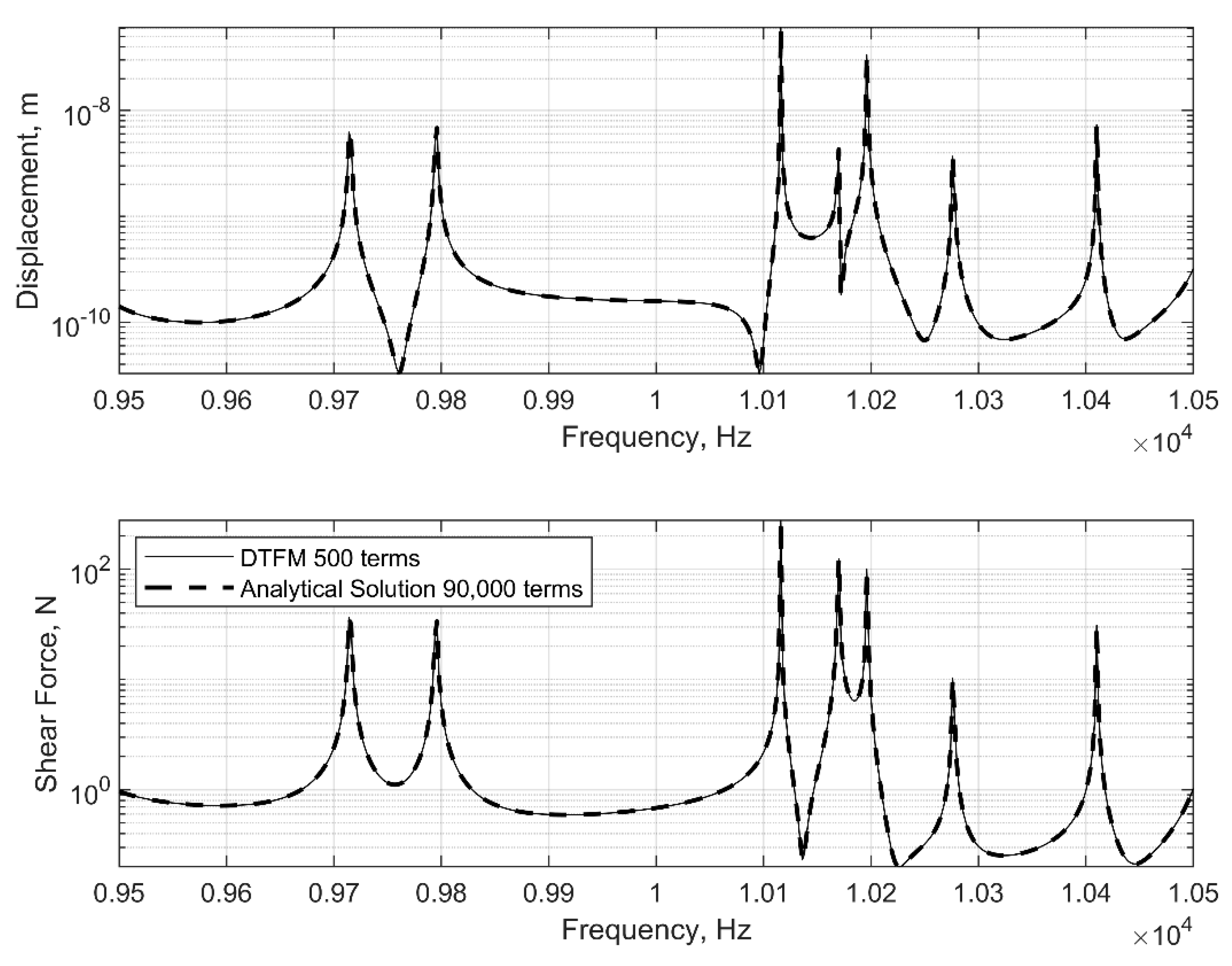
Now, examine the high-frequency vibration of the plate structure. Because the FEM is not suitable for mid- and high-frequency analysis, to validate the accuracy of the DTFM-based analysis at high frequencies, the analytical solution (Navier solution) for plates with the SSSS boundary condition is used [35]. The frequency response of the sandwich plate is computed in a high-frequency region, from 9500   H z to 10,500   H z , which includes the 347 th to 380 th natural frequencies of the undamped structure. Let the sinusoidal excitation be applied to the upper plate at the point ( x = 0.5   m , y = 0.9   m ) . In Figure 7, the magnitudes of the transverse displacement and shear force Q y   are plotted against the excitation frequency. It is seen that the frequency responses by the 500-term DTFM and 90,000-term series ( 300 × 300 ) match each other very well.
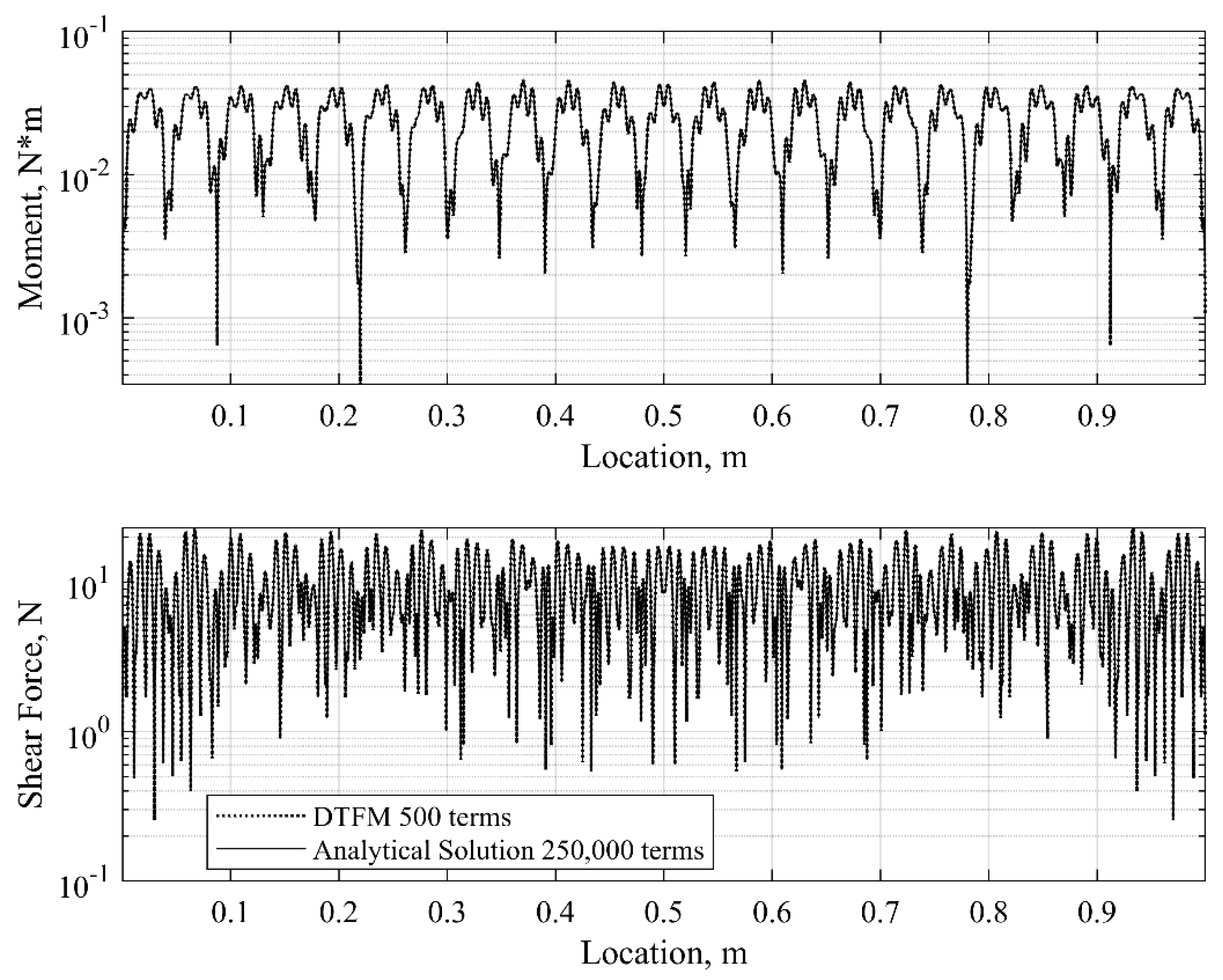
Finally, consider a relatively high excitation frequency, f = 5 × 10 6   H z . The plate structure has the SSSS boundary condition, and the viscoelastic layer is described by the Kelvin–Voigt model. Plotted in Figure 8 are the spatial distribution curves for the bending moment M y y and shear force Q y at point x = 0.5 m and y = 0.6 m on the lower plate. It is seen that the results obtained by the DTFM with 500 terms are in good agreement with those by the series solution with 250,000 ( 500 × 500 ) terms. The DTFM can give the plate responses at much higher frequencies without difficulty, in which case, the series solutions require a significantly larger number of terms in computation. Thus, the DTFM is shown to be able to deliver accurate plate responses at high frequencies.
In this benchmark example, the accuracy and efficiency of the proposed method is demonstrated through comparison with the FEM and the Navier series solutions, at both low and high frequencies. It should be pointed out that the Navier solution method is only limited to plates with SSSS boundary conditions. The proposed method, on the other hand, can easily handle different types of boundary conditions, which has been shown in the current example and which shall be shown in the subsequent two examples.

7.2. Example 2. A Double-Plate Structure with a Partially Distributed Viscoelastic Layer

Consider a double-plate structure with a partially distributed viscoelastic layer of the Kelvin–Voigt model, as shown in Figure 1c and Figure 2a. Assume that the two plate components are identical. For numerical simulation, the parameters of the plate structure are selected as follows:
a = 1   m ,   b 1 = 0.9   m ,   b = 1.5   m ,   2 h = 0.025   m ,   E = 200   G P a
ν = 0.3 ,   ρ = 7800   k g / m 3 ,   k v = 2.5 × 10 6   N / m ,   c v = 2.5 × 10 5   N s / m
Let both the plate components have the SCSC boundary conditions. Because of the boundary conditions, the Navier solution method is invalid here. A pointwise sinusoidal force, F f t = F 0 sin 2 π f t , is applied on the upper plate at the location x = 0.55   m and y = 1.125   m , where f is the excitation frequency in Hertz and F 0 = 1   N .
First, compute the natural frequencies of the undamped plate structure ( c v = 0 ). The proposed DTFM and the FEM with 50, 200, and 3200 elements are used. Listed in Table 3 are the first five and some higher-mode natural frequencies of the structure. It is seen that the predictions by the FEM, as the number of elements increases, converge with those exact solutions obtained by the DTFM.
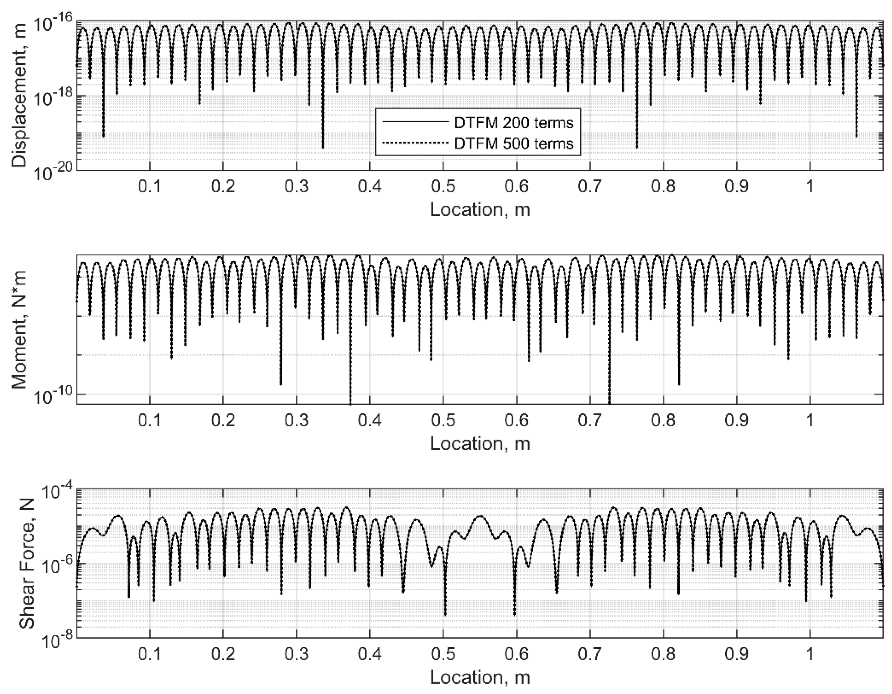
Next, compute the frequency response of the sandwich plate. Let the excitation frequency be f = 5000   H z , which is beyond the typical low-frequency region. In this case, the FEM would require a significant number of elements is required. For this reason, only the proposed DTFM is used in the simulation, with 50 terms and 500 terms from the series given by Equation (25). Shown in Figure 9 are the spatial distributions of the magnitudes of the transverse displacement, bending moment M y y , and shear force Q y of the upper plate at the point x = 0.55   m and y = 0.45   m . It is seen that the curves from the two DTFM solutions are in good agreement. Therefore, the 50-term DTFM is capable of providing good results at a higher frequency.
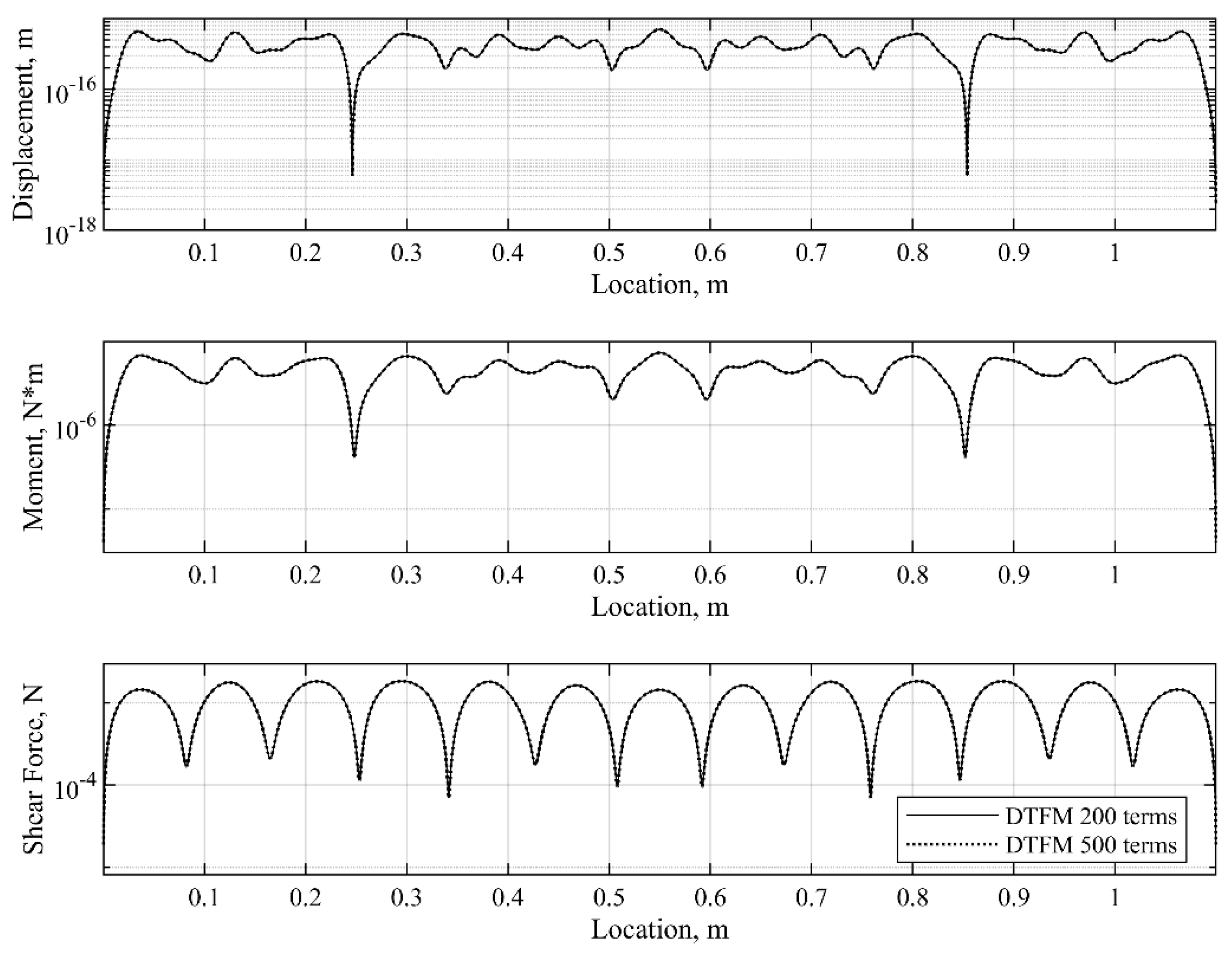
Consider an excitation frequency f = 2 × 10 5   H z . At this frequency, numerical simulations indicate that the DTFM with 50 terms from the series (25) is not accurate enough. Thus, the frequency responses of the sandwich plate are computed by the DTFM with 200 terms and 500 terms. The spatial distributions of the magnitudes of the displacement, moment, and shear force at the same point of the upper plate are plotted in Figure 10, which shows that the predictions by the 200-term DTFM and those by the 500-term DTFM match with each other well. This implies that the DTFM with 200 terms is accurate enough for vibration analysis at this high frequency.
Note that the computational efforts by the DTFM with 50, 200, and 500 terms do not differ much because 16 × 16 global state matrices are always used at any given frequency, as seen in Equations (45) and (46). The only difference is that different numbers of terms in Equation (25) are used, which in computation just involves simple algebraic summations. Thus, the DTFM is numerically accurate and computationally efficient for simulation analysis in mid- and high-frequency regions.

7.3. Example 3. A Three-Plate Structure with Dislocated Viscoelastic Layers

Figure 11 shows a three-plate structure with partially distributed and dislocated viscoelastic layers. In this structure, the top plate and the middle plate are coupled by the layer described by B B E E B , and the middle plate and the bottom plate are coupled by the layer described by C C F F C . Assume that the three plate components have identical parameters and that they all have the SFSF boundary conditions. For such a plate structure, no existing analytical solutions are available. For numerical simulation, the material parameters of the plates and the viscoelastic layers are the same as given in Example 2. Some geometric parameters of the plates are marked in Figure 11; others are specified as follows: a = 1.1   m and 2 h = 0.025   m . A pointwise sinusoidal force, F f t = F 0 sin 2 π f t , with F 0 = 1   N , is applied at the point ( x = 0.55   m , y = 1.2   m ) on the upper plate, which from the side view in Figure 11 coincides with point F.
The natural frequencies of the undamped plate structure ( c v = 0 ) are computed by the proposed DTFM and the FEM with 300, 1200, and 4800 elements. The results obtained are given in Table 4. A good agreement is seen between the DTFM and 4800-element FEM. Again, the results by the FEM converge with the DTFM predictions as the number of elements increases.
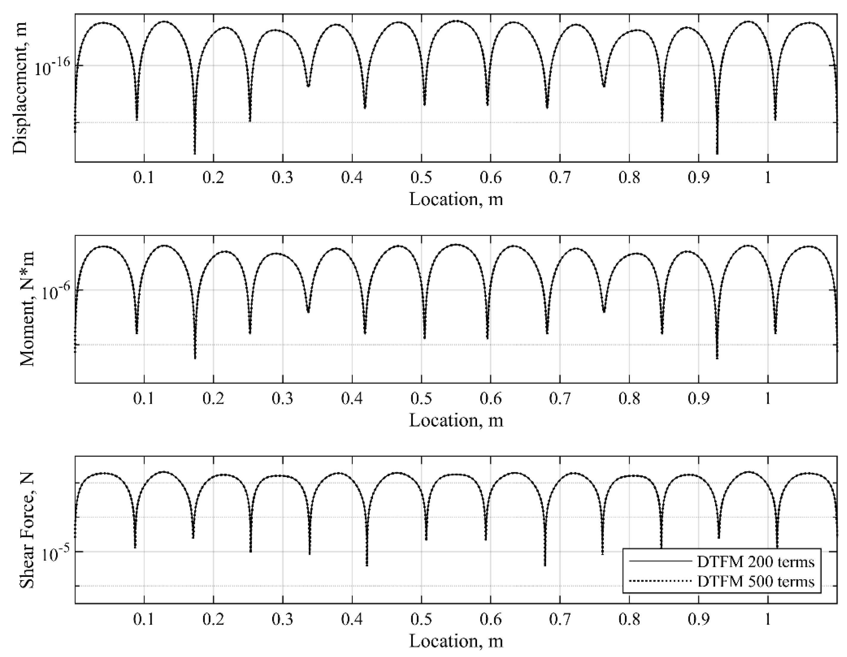
As mentioned in Section 4 and Section 5, different models of the viscoelastic layers can be easily implemented in vibration analysis with the state-space formulation in the DTFM. To show this, the standard linear solid models, as presented in Section 5.3, are implemented. First, consider the Kelvin representation, as given by Equation (55), with parameters k 1 , v = k 2 , v = 3 × 10 6   N / m and c v = 3 × 10 5   N s / m . Assume the same sinusoidal pointwise force as before. Set the excitation frequency as f = 2 × 10 5   H z . The spatial distributions of the magnitudes of displacement, moment M y y , and shear force Q y of the middle plate at point x = 0.55   m and y = 1.2   m are plotted in Figure 12. Here, the DTFM with 200 terms and the DTFM with 500 terms are used, and the computed results match very well. Second, implement the Maxwell representation, as given by Equation (57), with parameters k 1 , m = k 2 , m = 1.5 × 10 6   N / m and c v = 3 × 10 5   N s / m . The spatial distributions of the magnitudes of displacement, moment, and shear force of the middle plate at point x = 0.55   m and y = 1.2   m are plotted in Figure 13, where it is seen that the 200-term DTFM results and the 500-term DTFM results are in good agreement.
In Figure 12 and Figure 13, it is shown that the implementation of different viscoelastic material models in the DTFM-based vibration analysis, at different frequencies, is simple and straightforward.

8. Conclusions

A unified analytical solution method has been developed for vibration analysis of sandwich Lévy plates with viscoelastic layers. The main results obtained from this investigation are summarized as follows.
(1)
The proposed method, which is developed based on the Distributed Transfer Function Method (DTFM), provides an s -domain state-space formulation for multi-layer sandwich plates with various configurations (layouts) of viscoelastic layers. This formulation does not rely on any spatial discretization in modeling. As a result, closed-form analytical solutions to the frequency response problem of sandwich Lévy plates with various configurations are obtained for the first time.
(2)
One unique feature of the proposed method is that the model development and solution procedure for frequency responses remain unchanged in all frequency regions. This consistency in modeling and analysis differs from FEA-based methods, which need to implement mesh refinement at different frequencies. Accordingly, the DTFM-based approach provides a unified framework for frequency response analysis of sandwich Lévy plates over a wide frequency range.
(3)
The proposed method can effectively handle multi-layer sandwich plates with dislocated viscoelastic layers, and it can easily implement different models of viscoelastic materials. These issues would be extremely difficult to manage by conventional analytical methods, if not impossible.
(4)
Another special feature of the proposed method is that detailed local information of a sandwich plate in high-frequency vibrations, including the displacements, bending moments, and shear forces of a plate component at any location, can be conveniently obtained from the state vectors. On the other hand, FEA-based methods would require significant effort to determine shear forces, and energy-based methods have difficulty providing detailed local information about the plate response.
(5)
The proposed method is illustrated in three numerical examples, where the accuracy, efficiency, and versatility of the DTFM in computing the frequency responses of sandwich Lévy plates is validated through comparison with the FEM and analytical solutions (Navier solutions). It is shown that the DTFM-based analysis works in all frequency regions, from low to high frequencies. Moreover, the simulations reveal that the computational efforts required by the proposed method are much less than those needed by the existing methods.
The results presented in this paper indicate that the proposed DTFM is potentially useful for mid- and high-frequency analyses of sandwich Lévy plates. A thorough investigation into the characteristics of these plates at medium and high frequencies by the proposed method, which is beyond the scope of the current paper, will naturally follow.
While the main contribution of this work is on the analytical prediction of frequency response at both low and high frequencies, in solving the eigenvalue problem of a sandwich Lévy plate, the proposed DTFM is still limited to a relatively low frequency region. Indeed, accurate and efficient determination of the eigenvalue solutions at high frequencies remains a challenging problem for all of the existing solution methods. This issue may be worthy of research efforts in the future.

Author Contributions

Conceptualization and derivations, B.Y.; Derivations, analysis, and simulation, Y.Z. and B.Y.; Investigation, Y.Z. and B.Y. All authors have read and agreed to the published version of the manuscript.

Funding

This research received no external funding.

Institutional Review Board Statement

Not applicable.

Informed Consent Statement

Not applicable.

Data Availability Statement

Data is contained within the article. The original contributions presented in this study are included in the article. Further inquiries can be directed to the corresponding author.

Conflicts of Interest

The authors declare no conflict of interest.

References

  1. Mouritz, A.P.; Gellert, E.; Burchill, P.; Challis, K. Review of Advanced Composite Structures for Naval Ships and Submarines. Compos. Struct. 2001, 53, 21–42. [Google Scholar] [CrossRef]
  2. Ning, H.; Janowski, G.M.; Vaidya, U.K.; Husman, G. Thermoplastic Sandwich Structure Design and Manufacturing for the Body Panel of Mass Transit Vehicle. Compos. Struct. 2007, 80, 82–91. [Google Scholar] [CrossRef]
  3. Liaw, B.-D.; Little, R.W. Theory of Bending Multi-Layer Sandwich Plates. AIAA J. 1967, 5, 301–304. [Google Scholar] [CrossRef]
  4. Mead, D.J. Passive Vibration Control; John Wiley & Sons: New York, NY, USA, 1998. [Google Scholar]
  5. Marynowski, K. Free Vibration Analysis of the Axially Moving Lévy-Type Viscoelastic Plate. Eur. J. Mech. A Solids 2010, 29, 879–886. [Google Scholar] [CrossRef]
  6. Thai, H.T.; Kim, S.E. Levy-Type Solution for Free Vibration Analysis of Orthotropic Plates Based on Two Variable Refined Plate Theory. Appl. Math. Model. 2012, 36, 3870–3882. [Google Scholar] [CrossRef]
  7. Pradhan, K.K.; Chakraverty, S. Free Vibration of FG Levy Plate Resting on Elastic Foundations. Proc. Inst. Civ. Eng. Eng. Comput. Mech. 2016, 169, 3–28. [Google Scholar] [CrossRef]
  8. Demirhan, P.A.; Taskin, V. Levy Solution for Bending Analysis of Functionally Graded Sandwich Plates Based on Four Variable Plate Theory. Compos. Struct. 2017, 177, 80–95. [Google Scholar] [CrossRef]
  9. Yekani, S.M.A.; Fallah, F. A Levy Solution for Bending, Buckling, and Vibration of Mindlin Micro Plates with a Modified Couple Stress Theory. SN Appl. Sci. 2020, 2, 2169. [Google Scholar] [CrossRef]
  10. Sobhy, M.; Radwan, A.F. Levy Solution and State-Space Approach for Hygro-Thermo-Magnetic Bending of a Cross-Ply Laminated Plate on Kerr Foundation under Various Loadings. J. Compos. Mater. 2024, 59, 3–28. [Google Scholar] [CrossRef]
  11. Du, Y.; Tong, L. Exact Levy-Type Solution for Buckling of Rectangular Composite Plate Reinforced with Graphene Nanoplatelets. Int. J. Struct. Stab. Dyn. 2025, 2650252. [Google Scholar] [CrossRef]
  12. Oktem, A.S.; Algula, I. Boundary Discontinuous Fourier Solution of Thin Levy-Type Flat and Doubly Curved Shallow Shells. Steel Compos. Struct. 2024, 52, 595–608. [Google Scholar] [CrossRef]
  13. Rabbiolo, G.; Bernhard, R.J.; Milner, F.A. Definition of a High-Frequency Threshold for Plates and Acoustical Spaces. J. Sound Vib. 2004, 277, 647–667. [Google Scholar] [CrossRef]
  14. Cook, R.D.; Malkus, D.S.; Plesha, M.E.; Witt, R.J. Concepts and Applications of Finite Element Analysis, 4th ed.; Wiley: New York, NY, USA, 2001. [Google Scholar]
  15. Lu, Y.P.; Killian, J.W.; Everstine, G.C. Vibrations of Three Layered Damped Sandwich Plate Composites. J. Sound Vib. 1979, 64, 63–71. [Google Scholar] [CrossRef]
  16. Akoussan, K.; Boudaoud, H.; Daya, E.-M.; Carrera, E. Vibration Modeling of Multilayer Composite Structures with Viscoelastic Layers. Mech. Adv. Mater. Struct. 2015, 22, 136–149. [Google Scholar] [CrossRef]
  17. Zarrouk, T.; Nouari, M.; Salhi, J.-E.; Benbouaza, A. Numerical Simulation of Rotary Ultrasonic Machining of the Nomex Honeycomb Composite Structure. Machines 2024, 12, 137. [Google Scholar] [CrossRef]
  18. Lyon, R.H.; DeJong, R.G. Theory and Application of Statistical Energy Analysis, 2nd ed.; Butterworth-Heinemann: Oxford, UK, 1995. [Google Scholar]
  19. Zhou, R.; Crocker, M.J. Sound Transmission Loss of Foam-Filled Honeycomb Sandwich Panels Using Statistical Energy Analysis and Theoretical and Measured Dynamic Properties. J. Sound Vib. 2010, 329, 673–686. [Google Scholar] [CrossRef]
  20. Wang, T.; Li, S.; Rajaram, S.; Nutt, S.R. Predicting the Sound Transmission Loss of Sandwich Panels by Statistical Energy Analysis Approach. J. Vib. Acoust. 2010, 132, 011004. [Google Scholar] [CrossRef]
  21. Hwang, H.D.; Maxit, L.; Ege, K.; Gerges, Y.; Guyader, J.-L. SmEdA Vibro-Acoustic Modelling in the Mid-Frequency Range Including the Effect of Dissipative Treatments. J. Sound Vib. 2017, 393, 187–215. [Google Scholar] [CrossRef]
  22. Mace, B.R.; Duhamel, D.; Brennan, M.J.; Hinke, L. Finite Element Prediction of Wave Motion in Structural Waveguides. J. Acoust. Soc. Am. 2005, 117, 2835–2843. [Google Scholar] [CrossRef]
  23. Yang, Y.; Mace, B.; Kingan, M. Prediction of Noise Transmission through Honeycomb Sandwich Panels Using a Wave and Finite Element Method. In INTER-NOISE and NOISE-CON Congress and Conference Proceedings; Institute of Noise Control Engineering: Reston, VA, USA, 2018; Volume 257, pp. 122–132. [Google Scholar]
  24. Alam, N.; Asnani, N.T. Vibration and Damping Analysis of Multilayered Rectangular Plates with Constrained Viscoelastic Layers. J. Sound Vib. 1984, 97, 597–614. [Google Scholar] [CrossRef]
  25. Rao, M.K.; Desai, Y.M. Analytical Solutions for Vibrations of Laminated and Sandwich Plates Using Mixed Theory. Compos. Struct. 2004, 63, 361–373. [Google Scholar] [CrossRef]
  26. Foraboschi, P. Three-Layered Sandwich Plate: Exact Mathematical Model. Compos. Part B Eng. 2013, 45, 1601–1612. [Google Scholar] [CrossRef]
  27. Alaimo, A.; Orlando, C.; Valvano, S. Analytical Frequency Response Solution for Composite Plates Embedding Viscoelastic Layers. Aerosp. Sci. Technol. 2019, 92, 429–445. [Google Scholar] [CrossRef]
  28. Sabherwal, P.; Belarbi, M.-O.; Raman, R.; Garg, A.; Li, L.; Chalak, H.D.; Houari, M.S.A.; Avcar, M. Free Vibration Analysis of Laminated Sandwich Plates Using Wavelet Finite Element Method. AIAA J. 2024, 62, 824–832. [Google Scholar] [CrossRef]
  29. Wang, Y.; Cai, Y.; Hosen, K.; Pan, J. Free Vibration Properties of Novel Sandwich Plates with a Layered and Rotational Core. Eur. J. Mech. A Solids 2025, 111, 105588. [Google Scholar] [CrossRef]
  30. Wang, J.; Chang, Z.; Liu, T.; Chen, L. A Review of Linear and Nonlinear Vibration Analysis of Composite Laminated Structures by Computational Approaches: 2015–2024. Nonlinear Dyn. 2025, 113, 10839–10859. [Google Scholar] [CrossRef]
  31. Yang, B.; Noh, K. Distributed Transfer Function Method: One-Dimensional Problems in Engineering; De Gruyter: Berlin, Germany; ISBN 978-3110758542.
  32. Noh, K.; Yang, B. An Augmented State Formulation for Modeling and Analysis of Multibody Distributed Dynamic Systems. J. Appl. Mech. 2014, 81, 051011. [Google Scholar] [CrossRef]
  33. Zhang, Y.; Yang, B. Medium-Frequency Vibration Analysis of Timoshenko Beam Structures. Int. J. Struct. Stab. Dyn. 2020, 20, 2041009. [Google Scholar] [CrossRef]
  34. Liu, S.; Yang, B. A Closed-Form Analytical Solution Method for Vibration Analysis of Elastically Connected Double-Beam Systems. Compos. Struct. 2019, 212, 598–608. [Google Scholar] [CrossRef]
  35. Reddy, J.N. Theory and Analysis of Elastic Plates and Shells; CRC Press: Boca Raton, FL, USA, 2006. [Google Scholar]
  36. Christensen, R.M. Theory of Viscoelasticity: An Introduction, 2nd ed.; Elsevier: Amsterdam, The Netherlands, 2012. [Google Scholar]
  37. Zener, C. Elasticity and Anelasticity of Metals; University of Chicago Press: Chicago, IL, USA, 1948. [Google Scholar]
  38. Yang, B. Advanced Mechanical Vibration: Modeling, Analysis, and Simulation; McGraw Hill: New York, NY, USA, 2025; ASIN: B0D5K553DB. [Google Scholar]
Figure 1. Lévy plate structures: (a) a plate on a viscoelastic foundation; (b) a double-plate structure with a fully distributed viscoelastic layer; (c) a double-plate structure with a partially distributed viscoelastic layer; and (d) a three-plate structure with partially distributed and mislocated viscoelastic layers.
Applmech 06 00049 g001
Figure 2. A double-plate structure with a partially distributed viscous layer: (a) side view in the y z plane; (b) stepped configuration, with subsystems S 1 and S 2 .
Applmech 06 00049 g002
Figure 3. A three-plate structure with dislocated viscoelastic layers: (a) side view in the y z plane; (b) stepped configuration, with subsystems S 1 , S 2 , …, S 5 .
Applmech 06 00049 g003
Figure 4. Schematic of viscoelastic models: (a) the Kelvin–Voigt model; (b) the Maxwell model; (c) the Kelvin–Voigt representation of the standard linear solid model; and (d) the Maxwell representation of the standard linear solid model.
Applmech 06 00049 g004
Figure 5. The spatial distribution of the transverse displacement of a double-plate shown in Figure 1b, at f = 200   H z : solid line—DTFM with 50 terms; dashed line—FEM with 200 elements; dotted line—FEM with 3200 elements.
Applmech 06 00049 g005
Figure 6. The magnitude of transverse displacement of a double plate shown in Figure 1b, from f = 100   H z to f = 1000   H z : solid line—DTFM with 50 terms; dashed line—FEM with 200 elements; dotted line—FEM with 3200 elements.
Applmech 06 00049 g006
Figure 7. The magnitudes of the transverse displacement and shear force Q y of a double plate shown in Figure 1b, from f = 9500 Hz to f = 10,500 Hz: solid line—DTFM with 500 terms; dashed line—analytical solution with 90,000 terms.
Applmech 06 00049 g007
Figure 8. The spatial distribution of the magnitudes of the bending moment M y y and shear force Q y of a double plate shown in Figure 1b, at f = 5 × 10 6   H z : solid line—DTFM with 500 modes; dotted line—analytical solution with 250,000 terms.
Applmech 06 00049 g008
Figure 9. The spatial distributions of the magnitudes of transverse displacement, bending moment M y y , and shear force Q y of a double plate shown in Figure 1c, at f = 5000 Hz: solid line—DTFM with 50 modes; dotted line—DTFM with 500 terms.
Applmech 06 00049 g009
Figure 10. The spatial distributions of the magnitudes of transverse displacement, bending moment M y y , and shear force Q y of a double plate shown in Figure 1c, at f = 2 × 10 5   H z : solid line—DTFM with 200 terms; dotted line—DTFM with terms.
Applmech 06 00049 g010
Figure 11. A three-layer sandwich plate with partially connected viscoelastic layers; side view.
Applmech 06 00049 g011
Figure 12. The spatial distributions of the magnitudes of transverse displacement of a double plate shown in Figure 11, at f = 2 × 10 5   H z : solid line—DTFM with 200 terms; dotted line—DTFM with 500 terms.
Applmech 06 00049 g012
Figure 13. The spatial distribution of the magnitude of transverse displacement, bending moment M y y , and shear force Q y of a double plate shown in Figure 11, at   f = 2 × 10 5   H z : solid line—DTFM with 200 terms; dotted line—DTFM with 500 terms.
Applmech 06 00049 g013
Table 1. Natural frequencies f k of the elastically connected double-plate structure with SSSS boundary conditions ( H z ).
k FEM (Elements)DTFM
50200 3200
185.039086.426386.888286.9195
288.775790.105590.548690.5786
3161.1637165.4778167.0437167.1528
4163.1664167.4287168.9766169.0845
5260.1657265.3827267.3096267.4445
10323.0613341.1225348.1126348.6107
20599.0271645.5216667.3677669.0969
30897.0924983.4272989.3284989.8729
401067.65461164.95351204.18591210.4549
501361.60471510.59351546.70571551.3877
Table 2. Natural frequencies f k of the elastically connected double-plate structure with SCSC boundary conditions ( H z ).
k FEM (Elements)DTFM
50200 3200
1102.8850105.0855105.8691105.9233
2105.9944108.1316108.8933108.9460
3207.8806213.1652215.3394215.4956
4209.4369214.6833216.8422216.9973
5267.9959274.1810276.7941276.9834
10369.5161375.1433380.1241380.7771
20708.8662731.5818756.1503758.2217
30980.7883993.74291037.47661042.3999
401270.87571312.70181347.09521351.1562
501600.15921570.72941624.94801634.6596
Table 3. Natural frequencies f k of the double plate with a partially connected elastic layer with SCSC boundary conditions ( H z ).
k FEM (Elements)DTFM
50200 3200
1103.6084105.8236106.6055106.6595
2105.6672107.8404108.6079108.6609
3219.8495225.0578227.2117227.3665
4220.5723225.7630227.9101228.0644
5250.9591257.1126259.6909259.8766
10397.4359402.7193406.4568406.7532
20713.0100765.3261789.3563791.3876
30981.4164988.24761042.96941047.7172
401308.61361313.93111400.52201401.4399
501523.57471575.71781690.40221699.8813
Table 4. Natural frequencies f k of the three-layer plate ( H z ).
k FEM (Elements)DTFM
3001200 4800
153.782953.702853.682153.6752
254.944454.862354.841254.8341
357.455957.371457.349757.3425
475.183775.172375.168775.1674
575.508675.495675.491675.4902
10217.4733216.8162216.6319216.5686
20313.8678316.1529316.7388316.9354
30492.1189490.0905489.4404492.6234
40657.7398661.2479662.5154662.9800
50874.2904872.5249870.9846870.5649
Disclaimer/Publisher’s Note: The statements, opinions and data contained in all publications are solely those of the individual author(s) and contributor(s) and not of MDPI and/or the editor(s). MDPI and/or the editor(s) disclaim responsibility for any injury to people or property resulting from any ideas, methods, instructions or products referred to in the content.