1. Introduction
Advancement in aircraft engine performance usually requires an increase in speed and power in the turbomachinery, where issues related to rotor dynamic instabilities become very common. These instabilities can be triggered by destabilizing forces, varied temperature, material fatigue, etc. Due to the difficulty in tuning a system’s natural frequencies, modern aircraft engines have adopted squeeze film dampers (SFDs) to attenuate the structural vibration [
1].
SFD is a specific type of lubricant damping mechanism that has been widely implemented in aero-engine rotor systems to limit vibration level and reduce interior fuselage noise [
2].
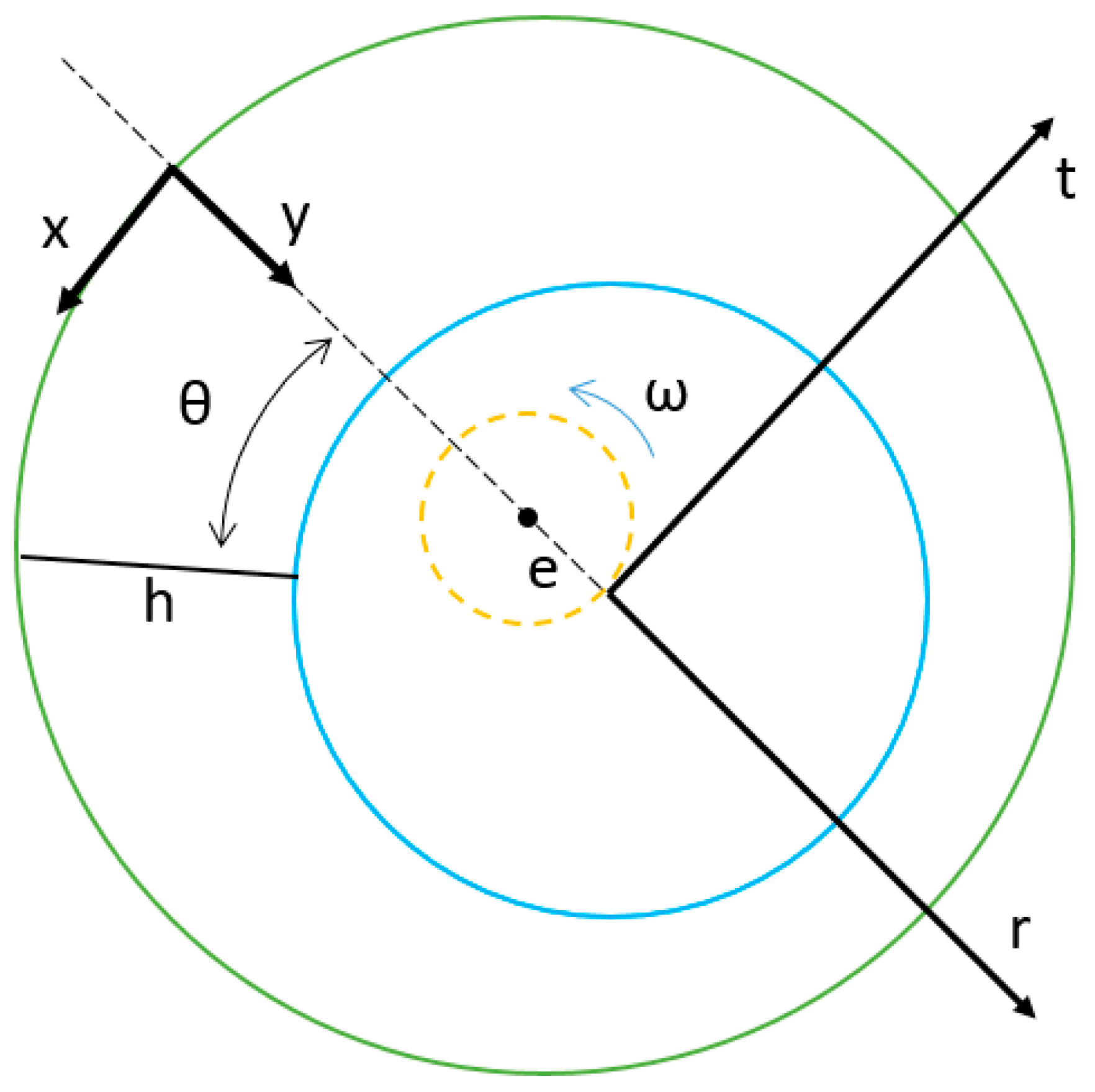
Figure 1 illustrates a typical SFD structure. It includes two solid components, i.e., an inner moving journal and a fixed outer housing. The journal is prevented from rolling by an anti-rotation pin, while it is free to move in a whirling motion. The small radial gap between the inner journal and outer housing is usually filled by lubrication oil to provide hydrodynamic force when the journal is whirling around. As a result, oil pressure generated in this thin film plays a critical role in determining the journal position and the force transmissibility in its applications.
Conventional theory applies the Reynolds equation to describe the pressure profile in the SFD oil film [
3]. This equation is derived from the fluid continuity equation and the momentum equation by disregarding the inertial effect. Accordingly, the Reynolds equation holds under the hypotheses of laminar, isoviscous lubricant flow in the absence of fluid inertia. However, closed-form solutions to the Reynolds equation have yet to be found except for some approximate answers [
4,
5]. The most acknowledged simplified models from the Reynolds equation are known as the short-bearing model and the long-bearing model, which are currently applied in SFD modelling for an aircraft rotor system. The short-bearing model has been generally accepted to study the open-ended dampers with small length-to-diameter ratios, while the long-bearing model provides better prediction in tightly sealed dampers.
Nevertheless, due to the trend towards the use of light-viscosity lubrication oil in high-speed turbomachinery with larger clearance, turbulent flow operating conditions have become very common in practical application [
6,
7,
8]. Classic turbulent lubrication theories have been developed from Prandtl’s mixing length model by Constantinescu [
9], to the linear turbulence model using the “law of wall” by Ng-Pan [
10], and to a bulk-flow theory by Hirs [
11]. Extensive analytical and experimental studies of turbulence in fully developed Couette and Poiseuille flows in narrow channels have been carried out [
12,
13,
14,
15,
16,
17]. Model correlations have been presented in hydrodynamic lubrication for Reynolds numbers between 2000 and 12,000 [
18]. A parametric study on water-lubricated rubber bearings shows the variances of applying different turbulent lubrication models [
19]. The critical Reynolds number in a tilting pad journal bearing is reported by a unified comparison of experimental works that validate different turbulence models [
20].
However, direct adoption of a general turbulence lubrication model in SFD applications warrants further discussion. Due to the difference in the nature of SFD physics that involves a squeezing flow, air entrainment is a common phenomenon at implementation in the absence of end seals [
21], which could influence the fluid viscosity at a significant level. Theoretical turbulence model development for SFD is rare. An empirical coefficient formula has been proposed in a turbulence SFD flow by San Andres [
6], while experimental study of turbulence squeezing flows remains obscure. Industrial practitioners find limited predictive capacity of existing SFD models if the turbulence effect is neglected.
This work aims to provide an analytical solution to the turbulence effect in SFD at an open-ended configuration. The conventional short-bearing assumption is applied to derive a modified Reynolds equation with a turbulence coefficient function. In short-bearing analysis, the axial flow is dominant in the thin film region; this model is generally applicable to lubricant bearings without the need for seals to limit the axial flow [
22,
23].
Prandtl’s mixing length hypothesis is used to determine the effective flow viscosity under turbulent conditions. Results are presented in terms of SFD damping coefficients at various scenarios. A comparison between a rotor-SFD test rig [
24,
25] and the analytical prediction is also presented to validate the feasibility of the developed model. The scope of the work is to present the efficiency of the new model considering the turbulence flow while minimizing the effect of other features such as fluid inertia, flow cavitation, grooves, and seals.
2. Model Development
Figure 2 shows the coordinate system used in SFD flow analysis. Let
be the effective viscosity under the turbulence influence, which determines the total shear stress in the turbulence flow as follows:
If Prandtl’s mixing length model is embraced to describe the momentum transfer, the total shear stress can be solved as the superposition of viscous shear stress and the Reynolds shear stress, i.e.,
where
Therefore, combing Equation (1) to Equation (4) provides an approach to relate the fluid viscosity
to the effective viscosity
under the turbulence effect, i.e.,
The mixing length function
in a thin film is defined as [
9], which treats the flow in the damper as a near-wall flow:
Equation (5) can be further written as follows in four different regions.
In region 1, where
,
In region 2, where
,
In region 3, where
,
In region 4, where
,
Assuming that the velocity profile is not affected by the turbulence in the squeezed film, the Reynolds equation for open-ended SFD can be reduced to the following by the short-bearing approximation in the absence of fluid inertia [
26]:
The boundary conditions in the axial direction (z) for an open-ended SFD typically assume that the pressure at the ends of the damper (z = 0, z = L) is equal to the ambient pressure. This boundary condition reflects the fact that the film of lubricant in the damper is exposed to ambient pressure at both ends. This is a reasonable assumption for open-ended dampers where the lubricant can flow freely in and out at the boundaries.
Integrating the above equation in the axial direction renders the solution of film pressure in time average, i.e.,
The time average of the axial flow velocity function for the Poiseuille flow is known as
Applying the same assumption for Equation (12), the time average of the axial flow velocity function can be written as
Combining Equation (13) to Equation (15) solves the time average of the axial velocity gradient, i.e.,
If Equation (16) is substituted into Equations (8)–(11), the effective viscosity can be described using the coordinate in the thin film. The following expresses the effective viscosity function in four regions, respectively.
If the bulk average in the radial and the axial directions is applied to evaluate the expression on the right side of Equations (17)–(20), i.e.,
Equations (17)–(20) can be reduced as follows for all defined four regions.
Further applying the bulk mean over the film circumference, i.e.,
Equations (25)–(26) can be rewritten as
where
Equation (29) determines effective fluid viscosity in a turbulent SFD film. It is a formulation consistent with boundary layer theory in thin-film flows, and it shows the turbulence effective viscosity is increased with the Reynolds number. Unlike any empirical formula for an ordinary lubrication film [
9,
10,
11], this expression includes special SFD features such as the length-to-radius ratio
L/
R and the eccentricity ratio
ε. This derived form is also in good agreement with an empirical formula for SFD films proposed by San Andres [
6].
Model Comparison
To compare the result, some empirical models and their formulas from the literature are selected, i.e.,
San Andres’ model [
6], which is analytically derived for SFD:
Constantinescu’s model [
9], which is also developed from Prandtl’s mixing length theory for a general lubricated bearing:
Ng-Pan’s model [
10], which uses a linear turbulence model to find a solution for lubricate bearings:
Hirs’ model [
11], which has a bulk-flow theory for lubricated bearings
3. Results and Discussion
3.1. Damping Coefficient
The first case study analyzes SFD damping coefficients, which are calculated at various eccentricity ratios under different Reynolds numbers.
The analytical dimensionless direct damping coefficient is defined as follows regardless of the presence of fluid inertia [
6]:
The effect of fluid turbulence can be assessed by modifying the above formula using an effective viscosity ratio μ
t/μ as follows since the viscous forces are proportional to the lubricant viscosity:
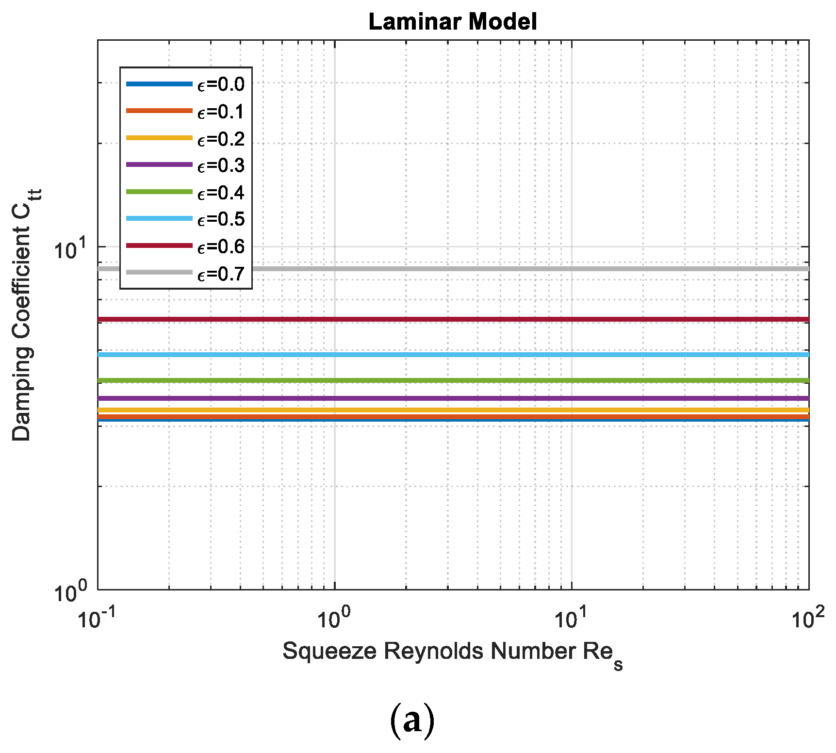
Figure 3 shows the SFD analytical damping coefficients at
L/
R = 0.25 and
c/
R = 0.001, where plots are shown in log scale. The horizontal axis is the squeeze Reynolds number
Res, which is a scaled form of the Reynolds number
Re by a factor of
c/
R.
Figure 3c is the reproduction of Figure 9 in reference [
6].
Figure 3a shows that the dimensionless damping coefficient is a function of the eccentricity ratio only under the laminar flow model. This damping coefficient increases nonlinearly with the eccentricity ratio, independent of the Reynolds number.
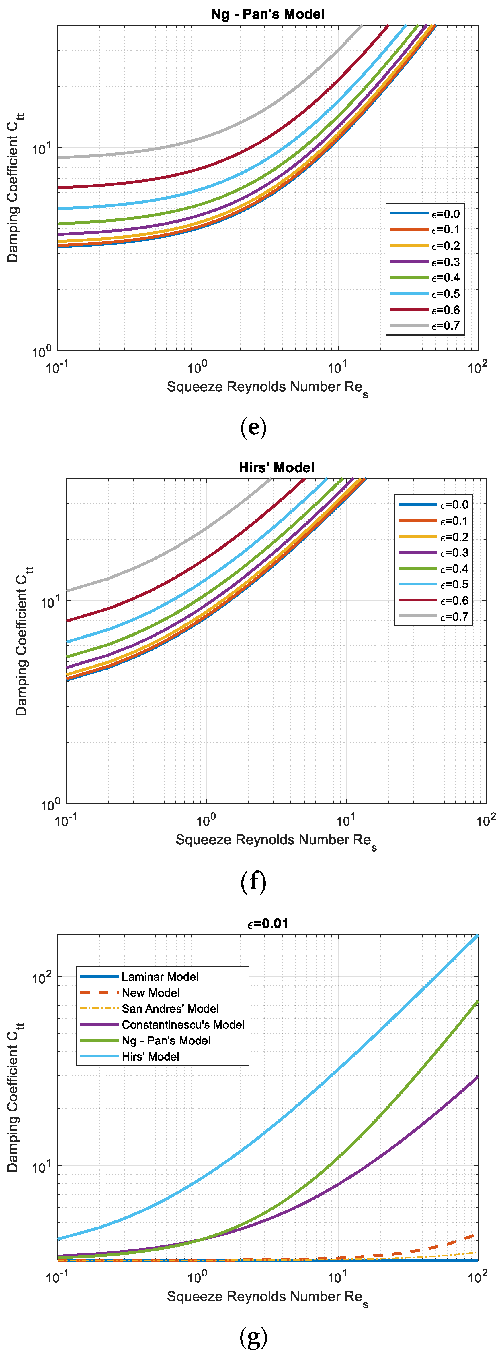
Figure 3b,c express that the damping coefficient gradually increases with the Squeeze Reynolds number, with the same trend seen in both SFD turbulence flow models. The differences in the damping coefficients at low Reynolds numbers are extremely small. Therefore, it can be concluded that the developed analytical SFD turbulence flow model has a good agreement with the previous SFD model in the regime of small turbulence.
Figure 3d–f plot the damping coefficients using empirical formulas from lubricated bearing experience. Compared with results from the designated SFD model in
Figure 3b,c, it is noted that the damping coefficients could be significantly overestimated if an empirical solution of a lubricated bearing is adopted in SFD applications. Constantinescu’s model, which is also developed from Prandtl’s mixing length theory, gives the closest predictions, whereas Hirs’ model provides the highest results. This outcome implies that a general turbulence-bearing model is not applicable in SFD. It also suggests the significance of our work in developing the analytical equation to correlate the empirical formula found in the past.
Figure 3g indicates that if the eccentricity is close to zero, both the new model and San Andres’ model predict the damping coefficient close to a constant value. The difference between the new model and San Andres’ model becomes more noticeable when the squeeze Reynolds number is greater than 10. A significant difference between these two models and other models can be noticed as well. This difference, which can be explained by Equations (31)–(34), where formulas are not functions of the eccentricity ratio, provides evidence that certain unique features in SFD must be considered when modeling the turbulence flow in the damper as opposed to the flow in general lubricant bearings.
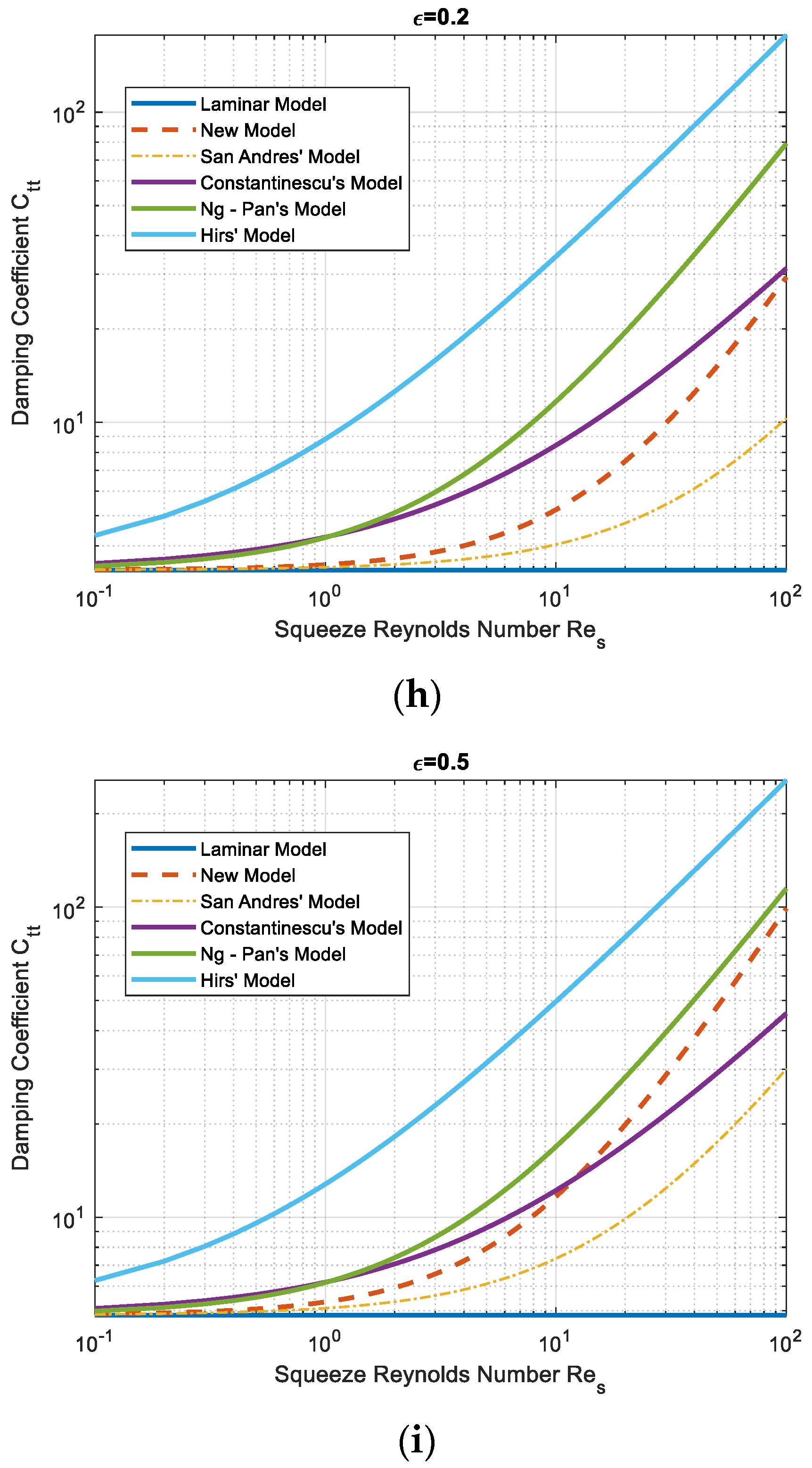
Figure 3h shows that when the eccentricity ratio is 0.2, both the new model and San Andres’ model calculate growing damping coefficients when the Reynolds number increases, whereas the other three turbulence flow models overestimate damping coefficients.
Figure 3i presents that when the eccentricity ratio reaches a moderate level of 0.5, the damping coefficient from the new model surpasses Constantinescu’s model at the squeeze Reynolds number of 10 and reaches a value close to Ng-Pan’s model prediction at the squeeze Reynolds number of 100. The higher significance of turbulence outcome is expected in the SFD when the whirling eccentricity ratio increases.
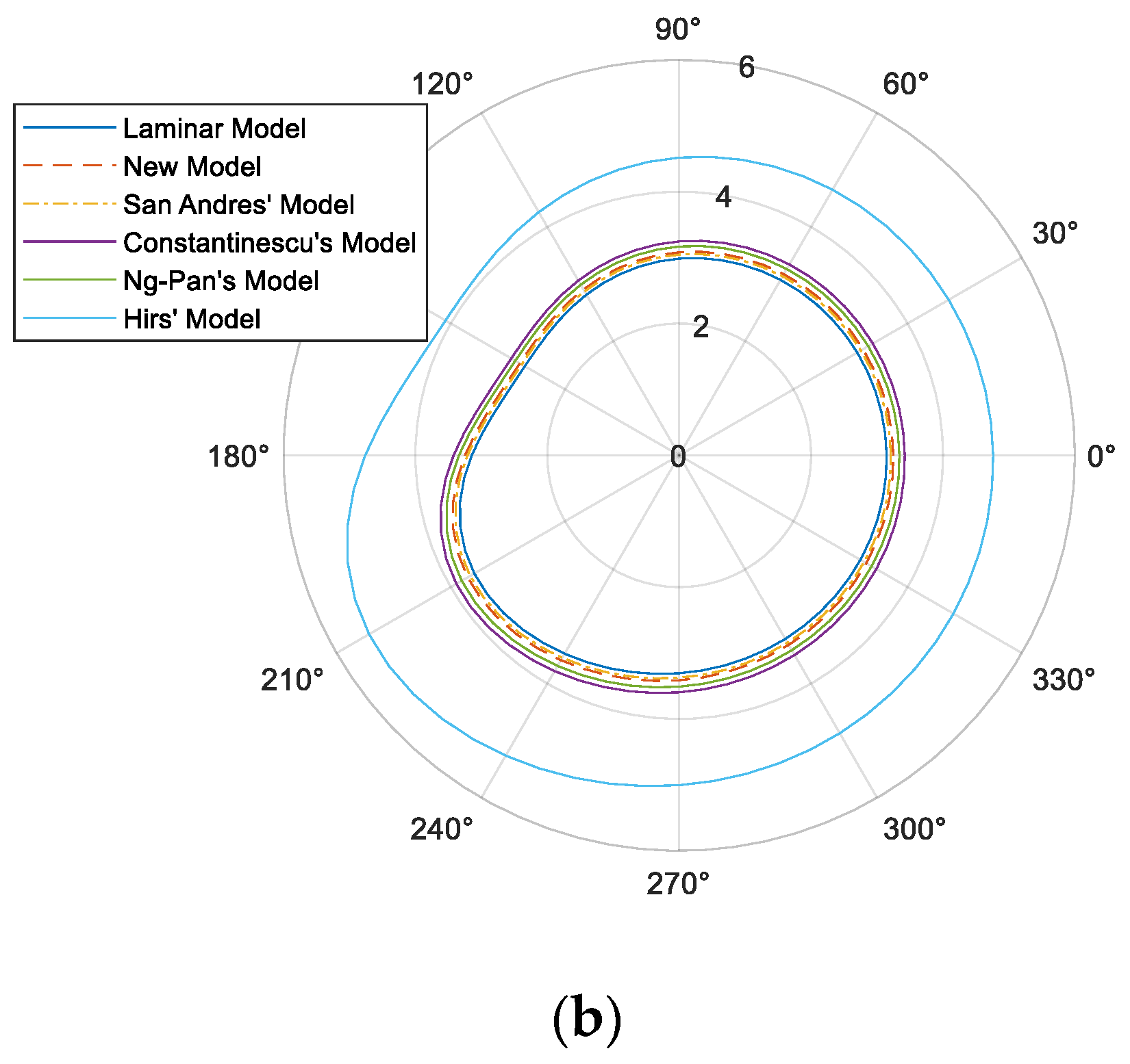
Figure 4a,b depict the pressure at the mid-plane location in the damper around the circumferential direction, where the Reynolds number is varied by the oil viscosity. The pressure is normalized by a factor of
. At small Reynolds numbers, where the oil viscosity is high, the fluid is not disturbed from the laminar flow. Cavitation takes place when the pressure fluctuation is not fully compensated by the supply. This film is cavitated at the 120° location, as shown in
Figure 4a, where a good agreement of the cavitation extent of 120–160° among all models has been seen. The onset of cavitation is determined by the rate of film thickness and the ambient pressure in the model. Hirs’ method overpredicts the unruptured pressure by about 15%, which is the result of a large coefficient for the Reynolds number in its empirical formula using Equation (34). At a larger Reynolds number where the oil’s physical viscosity is low, the deviation among different models becomes more obvious.
Figure 4b shows the overall higher normalized pressure as compared to
Figure 4a. This oil film is not cavitated because the viscous pressure fluctuation is small at low oil viscosity. This trend would be the opposite if the Reynolds number were varied by the operating speed instead of the viscosity. The laminar model provides the lower bound for the pressure, while the Hirs’ model gives the upper bound.
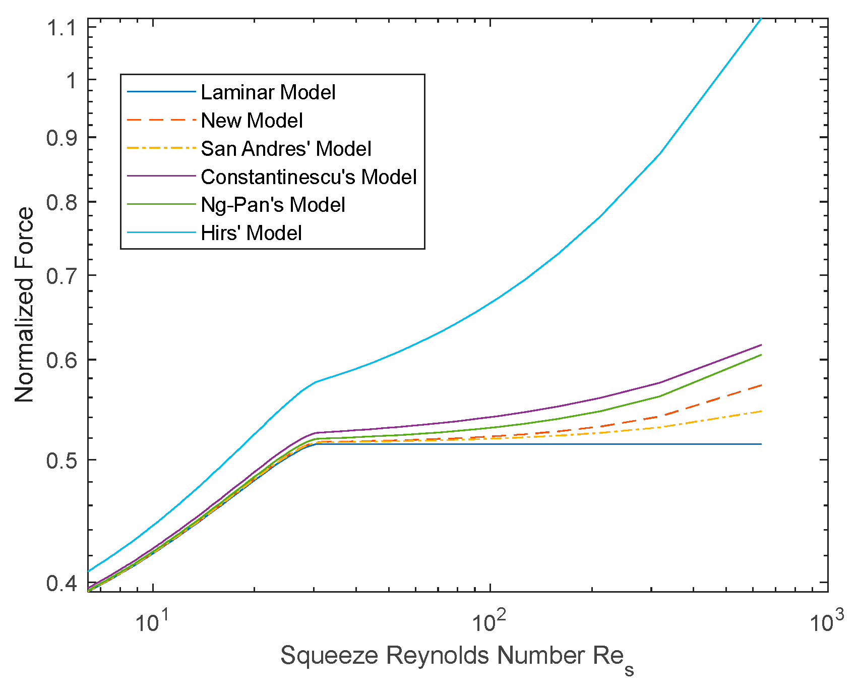
Figure 5 compares model predictions on the SFD bearing force under Squeeze Reynolds numbers varied by the oil viscosity. The bearing force is normalized by a factor of
. A step change has been seen on all curves at Squeeze Reynolds number near 30. It has been investigated to find out that the change in the force is influenced by the film cavitation at small Reynolds numbers, where the overall force is increased rapidly when the oil viscosity decreases. It is known that the extent of the cavitation region is very sensitive to the level of pressure oscillation. At high Reynolds numbers, where the viscosity is low, the viscous pressure is small so that the film cavitation is absent. The film remains unruptured, and the total force is increased gradually by the Reynolds number. Among all these turbulence models, the concurrent analytical model shows excellent agreement with other empirical models.
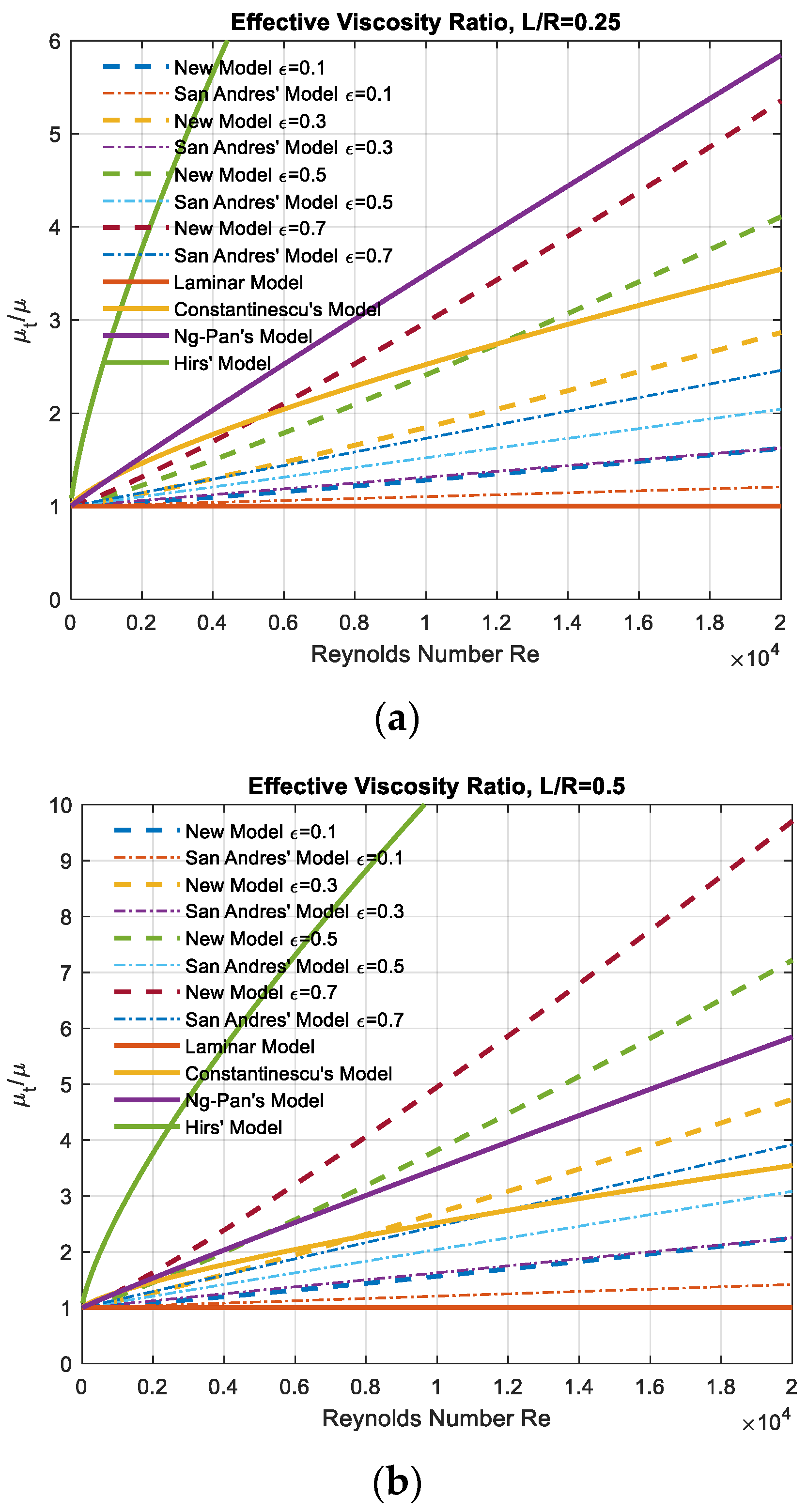
3.2. Effective Viscosity Ratio
To better understand the significance of the turbulence effect in different scenarios, the effective viscosity ratio μ
t/μ is calculated from the developed SFD model and other empirical lubricant bearing models. Higher values of μ
t/μ suggest more turbulence effect.
Figure 6 illustrates the trend to the Reynolds number at length-to-radius ratios
L/
R of 0.25 and 0.5, respectively.
For the three lubricant bearing models, Constantinescu’s predicts the lowest turbulence outcome, while Hirs’ provides the highest turbulence effect. Ng-Pan’s model becomes closer to Hirs’ model at high Reynolds numbers.
In SFD studies, higher eccentric operation leads to more turbulence effect since the fluid becomes violent with increased fluctuations. At small L/R scenarios (L/R = 0.25), the turbulence influence at small to moderate eccentricity ratios (ε ≤ 0.5) is generally less significant than that in a lubricant bearing. The turbulence effect at ε = 0.5 surpasses Constantinescu’s bearing model when the Reynolds number exceeds 12,000. For large eccentric motions (ε > 0.5), the turbulence effect in SFD gets closer to Ng-Pan’s bearing model.
At large L/R scenarios (L/R = 0.5), more significant turbulence influences are seen in SFD. The turbulence effect at ε = 0.3 exceeds Constantinescu’s model at Re = 8000. The effect at ε = 0.5 outstrips Ng-Pan’ and Hirs’ at Re = 6000 and Re = 15,000, respectively. Larger eccentric motion of SFD has a turbulence effect that outshines the bearing model at lower Reynolds numbers.
The above results suggest that if the SFD is executed at small eccentric motions, the turbulence impact is generally less than that in a common lubricant bearing. For a short (small L/R ratio) open SFD, the turbulence effect at low Reynolds number (Re < 5000) is less than a lubricant bearing even at high eccentric operations. However, if the SFD is relatively long (big L/R ratio), more turbulence influences would be seen from moderate to high eccentric processions.
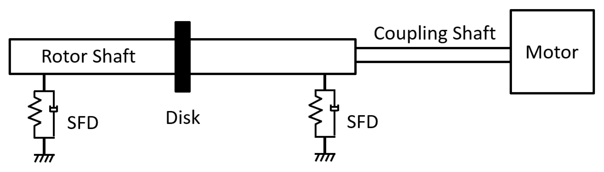
3.3. Rotordynamics Implementation
To further validate the new model and to better understand the effect of turbulence in a practical application, an experimental study [
25] of SFD in a high-speed rotor system is selected. This SFD test rig has been well calibrated and reliably used for over eight years, making it a trusted platform for high-fidelity experimental investigation.
Figure 7 shows the layout of the test rig, where the rotor shaft is lifted by two near-symmetric supports with identical SFDs. The rotor shaft made of AISI 4140 steel has a mass of 20.84 kg. For reasons of confidentiality, the dimensions of the test rig have been nondimensionalized with respect to the shaft outer diameter,
Dso, as shown in
Table 1. During the test, the damper was fed with an excessive oil supply to minimize the air entrainment effect. The measured temperature variation across the film is negligible.
In the simulation, an 82-uniform-element Timoshenko beam model is created for the rotor shaft. The central disk and the coupling shaft are modeled by lumped mass and inertia. To calculate the unbalance response, the speed of the rotor shaft is increased from static to its maximum level in 10 s, with an increment of 1 microsecond for the time integration. The Newmark-beta method is applied to solve for the acceleration that is induced by the unbalanced mass on the central disk.
Figure 8 and
Figure 9 illustrate the rotor response at low and high oil temperatures, 100 °F and 200 °F of Type II jet oil, respectively. The normalized frequency is defined as Equation (1) in reference [
25]. The sensitivity is defined as the ratio between the displacement and the unbalanced mass.
Since low-temperature oil has high viscosity, SFD provides high damping force during this operation. Therefore, the critical speed is high under cold oil supply conditions, and the SFD rigidifies the rotor-SFD system.
Figure 8 confirms that the turbulence model predicts the same result as the laminar model at low oil temperature. This result is expected since the Reynolds number is small at high oil viscosity, i.e.,
Re = 2000,
Res = 24. Therefore, an identical prediction is attained.
On the other hand,
Figure 9 shows that fluid turbulence reduces the disk amplitude by 10% at the critical speed compared to the laminar model. This phenomenon is induced by the temperature sensitivity of the oil, where the lubricant viscosity is decreased by three times at the test high temperature. As a result, the Reynolds number, which equals 4500 at the critical speed, is high enough to distinguish the turbulence effect. The corresponding squeeze Reynolds number
Res equals 55 in this condition.
The deviation between the theoretical model and the test results requires further investigation. The rotor support structure, which is modeled as a rigid support in simulation, might have a mode at 0.5 normalized frequency because a dip in the response has been recorded in the test. This frequency is absent in the rotor-alone tap test.
4. Discussion
The methodology presented in this work specifically addresses turbulence effects in SFDs under open-end boundary conditions. It is not intended to model other damper-specific characteristics such as cavitation or feeding groove effects. Nevertheless, the proposed method is modular and can be integrated into more comprehensive models without altering the core framework.
Cavitation can be incorporated through the application of appropriate boundary conditions, allowing its onset and extent to be captured using a dedicated cavitation algorithm. Within the full-film regions, the modified viscosity formulation remains valid and continues to govern the flow behavior, independent of the cavitation treatment applied at the boundaries.
Grooves, on the other hand, can be modeled as discrete regions with locally increased film thickness. These can be treated as special damping zones within the system, effectively modifying local flow resistance and dynamic response. Importantly, the influence of grooves can be incorporated regardless of whether the flow is laminar or turbulent, due to the model’s generalization via the effective viscosity term. As such, grooves can be readily embedded in the numerical domain by adjusting the local film geometry and re-evaluating the flow factors accordingly.
While the turbulence model provides reasonable accuracy across a broad range of flow conditions, its applicability might be limited at very high Reynolds numbers, where inertial effects are dominant. The model is developed in the absence of fluid inertia; whether the same formula applies when inertia becomes significant remains an open question. In such regimes, some underlying assumptions, such as parabolic velocity profile, begin to break down. As a result, the model may fail to capture the complex, nonlinear dynamics and flow instabilities that characterize high-inertia environments.
The experimental rig applied to validate the model this study offers unique and valuable features. Unlike typical SFD test rigs, which often operate at relatively low speeds and enforce a controlled orbital motion, this rig offers the exceptional capability of running the dampers with a high-speed rotor. This distinct advantage makes it particularly well-suited for exploring dynamic behaviors not accessible with conventional low-speed setups. Future studies will aim to complement these results with additional configurations to generate high Reynolds number flows with strong inertia effects. The objective of such experiments would be to evaluate the model’s predictive validity under high-inertia conditions and to identify the onset and impact of inertial deviations.
5. Conclusions
This work derives an analytical solution to address the turbulence effect on SFD applications. The new model applies Prandtl’s mixing length hypotheses to find an effective viscosity coefficient to quantify the fluid turbulence impact in SFD at different operating circumstances. Results from this method correlate excellently with the empirical turbulence model in literature.
The damping coefficients obtained using different models exhibit the same trend with the Squeeze Reynolds number. The differences in the damping coefficient between the two SFD turbulent models are extremely small at Squeeze Reynolds numbers less than 10. For large Squeeze Reynolds numbers, the proposed model predicts higher damping coefficients than the previous model.
Conventional turbulence lubrication theories overpredict the damping coefficients in general. For small eccentricity motions, they deviate marginally from the results of SFD turbulence theory. At moderate to large eccentricities, the developed SFD turbulent model has predictions closer to those from conventional turbulence lubrication theories than the previous SFD turbulent model.
In addition, the rotor dynamic simulation further validates the developed SFD model in its application. It is shown that the influence of flow turbulence in SFD is negligible at low oil temperature, while it is noticeable when the fluid viscosity drops due to a higher oil temperature, which enlightens the significance of involving turbulence study in light-viscous lubrication, especially at high-speed performance.
It must be mentioned that if the damper seal is present, the inertia forces can be of the same order of magnitude as the viscous force. In the high Reynolds number flow regime, both temporal fluid inertia and convective fluid inertia should be considered. Such turbulent and inertia-dominated problems require further effort to develop analytical solutions for practical applications.
To conclude, unique flow theory is essential to estimate the turbulence effect in the SFDs. Due to its competitiveness and sensitivity, the developed turbulence model has proved to serve as a powerful tool in open-ended SFD implementations.
Author Contributions
Conceptualization, T.F.; Methodology, T.F.; Software, T.F.; Validation, T.F.; Formal analysis, T.F.; Investigation, T.F.; Resources, K.B.; Writing—original draft, T.F.; Writing—review & editing, T.F.; Supervision, K.B.; Project administration, K.B.; Funding acquisition, K.B. All authors have read and agreed to the published version of the manuscript.
Funding
This research was funded by Pratt & Whitney Canada and Mitacs Canada.
Institutional Review Board Statement
Not applicable.
Informed Consent Statement
Not applicable.
Data Availability Statement
Data is contained within the article. The original contributions presented in this study are included in the article. Further inquiries can be directed to the corresponding author(s).
Acknowledgments
Special thanks are given to Dennis Chan and David Beamish for reviewing and providing invaluable input.
Conflicts of Interest
The paper reflects the views of the scientists and not the company.
Nomenclature
| SFD film radial clearance |
| SFD damping coefficient |
| SFD eccentricity, i.e., distance between bearing center and housing center |
| SFD film thickness, |
| SFD axial length |
| Time average of pressure in SFD film |
| Reynolds number, |
| Squeeze Reynolds number, |
| Time average of axial flow velocity |
| Circumferential direction, |
| Radial direction |
| Axial direction |
| Journal eccentricity ratio, |
| Karman’s constant, |
| Angular direction |
| Lubricant density |
| Fluid shear stress |
| Reynolds shear stress |
| Viscous shear stress |
| Lubricant viscosity |
| Turbulence effective lubricant viscosity |
| Journal angular whirling speed |
References
- Magge, N. Philosophy, design and evaluation of soft-mounted engine rotor systems. J. Aircr. 1975, 12, 318–324. [Google Scholar] [CrossRef]
- Mir-Haidari, S.E.; Behdinan, K. On the vibration transfer path analysis of aero-engines using bond graph theory. Aerosp. Sci. Technol. 2019, 95, 105516. [Google Scholar] [CrossRef]
- Della Pietra, L.; Adiletta, G. The squeeze film damper over four decades of investigations. Part I: Characteristics and operating features. Shock. Vib. Dig. 2002, 24, 3–26. [Google Scholar]
- Warner, P.C. Static and Dynamic Properties of Partial Journal Bearings. J. Basic Eng. 1963, 85, 247–255. [Google Scholar] [CrossRef]
- El-Shafei, A. Perturbation Solution for Finite Squeeze-Film Dampers Executing Linear Motion. Tribol. Lett. 2003, 14, 111–121. [Google Scholar] [CrossRef]
- San Andres, L.; Vance, J.M. Effects of fluid inertia and turbulence on the force coefficients for squeeze film dampers. J. Eng. Gas Turbines Power. 1986, 108, 332–339. [Google Scholar] [CrossRef]
- Ku, C.; Tichy, J.A. Application of the k-ε Turbulence Model to the Squeeze Film Damper. ASME J. Tribol. 1987, 109, 164–168. [Google Scholar] [CrossRef]
- Defaye, C.; Arghir, M.; Bonneau, O.; Carpentier, P.; Debailleux, C.; Imbourg, F. Experimental study of the radial and tangential forces in a whirling squeeze film damper. Tribol. Trans. 2006, 49, 271–278. [Google Scholar] [CrossRef]
- Constantinescu, V.N. On turbulent lubrication. Proc. Inst. Mech. Eng. 1959, 173, 881–900. [Google Scholar] [CrossRef]
- Ng, C.W.; Pan, C.H.T. A linearized turbulent lubrication theory. J. Basic. Eng. 1965, 87, 675–688. [Google Scholar] [CrossRef]
- Hirs, G.G. A bulk-flow theory for turbulence in lubricant films. J. Lubr. Tech. 1973, 95, 137–146. [Google Scholar] [CrossRef]
- Elrod, H.G., Jr.; Ng, C.W. A Theory for Turbulent Fluid Films and Its Application to Bearings. ASME J. Lubr. Tech. 1967, 89, 346–362. [Google Scholar] [CrossRef]
- Hirs, G.G. A Systematic Study of Turbulent Film Flow. ASME J. Lubr. Tech. 1974, 96, 118–126. [Google Scholar] [CrossRef]
- El Telbany, M.M.M.; Reynolds, A.J. The Structure of Turbulent Plane Couette Flow. ASME J. Fluids Eng. 1982, 104, 367–372. [Google Scholar] [CrossRef]
- Tsanis, I.; Leutheusser, H. The structure of turbulent shear-induced countercurrent flow. J. Fluid Mech. 1988, 189, 531–552. [Google Scholar] [CrossRef]
- Leutheusser, H.J.; Aydin, E.M. Plane-Couette flow between smooth and rough walls. Exp. Fluids 1991, 11, 302–312. [Google Scholar]
- Franchek, N.M.; Childs, D.W.; San Andres, L. Theoretical and Experimental Comparisons for Rotordynamic Coefficients of a High-Speed, High-Pressure, Orifice-Compensated Hybrid Bearing. ASME J. Tribol. 1995, 117, 285–290. [Google Scholar] [CrossRef]
- Wang, X.; Zhang, Z.; Sun, M. A Comparison of Flow Fields Predicted by Various Turbulent Lubrication Models with Existing Measurements. J. Tribol. 2000, 122, 475–477. [Google Scholar] [CrossRef]
- Du, Y.; Lan, J.; Quan, H.; Sun, C.; Liu, X.; Yang, X. Effect of different turbulent lubrication models on the lubrication characteristics of water-lubricated rubber bearings at a high Reynolds number. Phys. Fluids 2021, 33, 065118. [Google Scholar] [CrossRef]
- Betti, A.; Forte, P.; Ciulli, E. Turbulence Effects in Tilting Pad Journal Bearings: A Review. Lubricants 2022, 10, 171. [Google Scholar] [CrossRef]
- San Andrés, L.; Diaz, S. Flow visualization and forces from a squeeze film damper operating with natural air entrainment. J. Tribol. 2003, 125, 325–333. [Google Scholar] [CrossRef]
- Tan, Q.; Li, W.; Zhang, J. Fluid Forces in Short Squeeze-film Damper Bearings. Tribol. Int. 1998, 30, 733–738. [Google Scholar]
- Adiletta, G.; Della Pietra, L. Experimental Study of a Squeeze Film Damper with Eccentric Circular Orbit. J. Tribol. 2006, 128, 365. [Google Scholar] [CrossRef]
- Iacobellis, V.; Behdinan, K.; Chan, D.; Beamish, D. Effect of hole feed system on the response of a squeeze film damper supported rotor. Tribol. Int. 2020, 151, 106450. [Google Scholar] [CrossRef]
- Iacobellis, V.; Behdinan, K.; Chan, D.; Beamish, D. Experimental Investigation of the Effects of Squeeze Film Damper Design on Highspeed Rotor System. ASME Turbo Expo Power Land Sea Air 2020, 84225, V10BT29A001. [Google Scholar]
- Szeri, A.Z. Fluid Film Lubrication; Cambridge University Press: Cambridge, MA, USA, 2011. [Google Scholar]
| Disclaimer/Publisher’s Note: The statements, opinions and data contained in all publications are solely those of the individual author(s) and contributor(s) and not of MDPI and/or the editor(s). MDPI and/or the editor(s) disclaim responsibility for any injury to people or property resulting from any ideas, methods, instructions or products referred to in the content. |
© 2025 by the authors. Licensee MDPI, Basel, Switzerland. This article is an open access article distributed under the terms and conditions of the Creative Commons Attribution (CC BY) license (https://creativecommons.org/licenses/by/4.0/).


