1. Introduction
Numerical simulations have become an indispensable element of the further development of processes and tools for metal cutting [
1] and metal forming [
2]. One of the most influential inputs in the underlying models is the description of plastic material behavior, where adequate modeling primarily requires a suitable material characterization [
3]. In the case of chip formation simulations, however, material characterization is challenging as a result of high strains (up to 1000%), strain rates (up to 10
6 s
−1), and temperatures (more than 1000 °C). In order to achieve a realistic representation of the chip formation zone, these parameters have to be considered [
4]. A proven method for characterizing plastic deformation behavior at high strain rates is the SHPB test. In this experiment, a highly dynamic impulse is introduced into a bar system (comprising incident and transmission bars). The specimen is positioned between those two bars and thus deformed. Strain measurements applied to the bars can be used to estimate the plastic deformation behavior of the specimens. To assess the thermal conditions in the chip formation zone, SHPB test rigs can be extended by heating devices. High temperatures and heating rates are needed to adequately fit the conditions in cutting. Therefore, inductive specimen heaters are the most suitable method for this purpose [
5]. The history and more details on the principle of the test can be found in [
6].
Although the experimental principle of the SHPB has been known and proven for a long time, the results are used in increasingly complex plasticity models, which is why a further addition of multi-axial deformations and the improvement of accuracy in SHPB tests is an important objective. It should be noted that the measurements and evaluations based on strain gauges are accompanied by simplifying assumptions. Within these tests, there are deviations from these assumed ideal conditions depending on the detailed test setup, the material to be tested, and the specimen geometry. Moreover, the history of deformation, which also influences the flow stress behavior [
7], can only be mapped to a limited extent by such measurements. In their study, Lu et al. found that, despite high-quality specimen preparation and the tribological processes in the interface of the specimen and the bars, the influence of face friction cannot be neglected, as it influences the measurement results [
8]. Jaspers and Dautzenberg further explained that inhomogeneous material deformation occurs when using conventional cylindrical specimens since, contrary to theoretical assumptions, friction at the end faces cannot be avoided completely. For this reason, they use so-called Rastegaev specimens, which exhibit a reduced cross-sectional area at the end face. However, this leads to a higher preparation effort. Moreover, it is not fully known how this specimen geometry affects the deformation in addition to the friction reduction [
9].
In addition to the friction between the specimen and the bar, another challenge in characterization accuracy occurs for materials that tend to have inhomogeneous deformation behaviors, which is also the case for titanium alloys [
10]. Ran et al. investigated the flow-stress behavior of a different titanium alloy over a wide range of strain rates. As is typical for titanium materials, shear bands and cracks appeared in several specimens, particularly at high strain rates and high temperatures. Qualitative statements on the shear behavior could be made by subsequent analysis of the specimens. However, these results cannot be transferred into a quantitative analysis by evaluating the measurement signals at the SHPB [
11].
High-speed cameras represent a promising approach for quantifying the inaccuracy in the evaluation of SHPB tests, achieving an appropriate compensation, and developing alternatives for quantifying deformation behavior. However, since very high recording rates are required to capture the highly dynamic deformation in SHPB, this possibility has only existed for a few years, and the number of publications on this topic is still fairly low. In 2005, Whitenton reported on a SHPB test rig with a high-speed camera [
12]. At that time, however, no quantitative evaluation of the images to determine the strains was possible. The measurement of SHPB using DIC is still not a common procedure. While Cao et al. performed a DIC-based strain measurement in quasi-static tensile tests, the SHPB tests presented in this work were performed without DIC [
13]. The usage of DIC in quasi-static tensile tests has been proven to be valid and corresponds with measurements by means of a tactile extensometer [
14]. Cui et al. did not apply a high-speed camera directly to the SHPB, but compared strain measurement results from chip pulling experiments using a high-speed camera setup, with results from SHPB. In the chip pulling experiments, digital image correlation (DIC) in combination with force measurements is used for flow stress characterization. In this case, the difference in flow stress between the chip pulling experiments and the SHPB experiments was only 3%. However, the results of the two test setups are not fully comparable in terms of the boundary conditions [
15]. In contrast to this study, Lee and Huh used a high-speed camera for shear and tension flow stress characterization experiments on two different devices, leading to a large interval of strain rates between
= 0.001 … 1000 s
−1. For this purpose, a new kind of shear specimen was developed, which was designed with the help of finite element simulations. The experiments identified a significant effect of the strain rate on the flow stress for shear and tension experiments, as well as differing effects between the two deformation modes. At low strain rates, the flow stress in the shear case is below that of the tension case, but then it increases more rapidly as the strain rate increases and exceeds tension from about
= 10
3 s
−1 [
16]. In a comparable work on shear flow stress characterization at the SHPB, Jia et al. developed a novel design for a shear specimen and characterized the shear deformation over a wide strain rate interval. The measurements and subsequent calculations of strain, strain rate, and yield stress based on strain gauges for their specimen showed a large deviation compared to evaluations using a high-speed camera, as the strain gauges were not suitable for complex specimen geometries. Based on these findings, a correction factor for the strain-gauge-based flow curve calculation was developed from the high-speed DIC measurements [
17]. Another possible application for using high-speed cameras in SHPB measurements was found by Guo et al. They used DIC analysis for strain and strain rate measurements, in addition to strain gauges, measuring stress in SHPB tests on composite specimens of pure titanium and Ti6Al4V. The motivation for these combined analyses is to determine which portion of the deformation and material failure occurs in which part of the composite specimen. It is known that the role of DIC analysis in SHPB needs further investigation [
18].
Challenges regarding the application of high-speed cameras with subsequent DIC analysis in SHPB occur due to the high testing speeds, and thus the high strain rates, which emerge during those tests. The nominal strain rate during SHPB tests with standardized specimen geometries is usually about 2000 s−1, meaning a minimum recording rate of 10,000 Hz is necessary to receive at least one picture within the test time.
High-speed camera detectors are designed to perform pixel reading line-wisely, so higher recording rates can only be achieved by reducing the number of pixels of the frame. In addition, a small specimen geometry is used in SHPB tests, further impeding the resolution of the recorded area of the specimen. Since the specimens to be observed are cylindrical, they exhibit a curved surface, which generally leads to a smaller light output, following the scattered reflection of additional light sources. However, this light output is needed for the detector of the camera in order to minimize exposure times and thus maximizing recording rates. Additionally, the curved surface and thus the scattered reflection of the light also results in varying light outputs depending on the radial position, since the amount of reflection of ambient and additional light sources is different. As a consequence, the usage of polarizing filters, which absorb certain light directions, is mandatory. In doing so, the overall amount of light output is decreased. It is assumed that the validity of the DIC results is greater than those obtained by strain gauges, since variations in the behavior of different specimens, as well as inhomogeneous deformations, are considered.
Due to the high deformation speed in SHPB tests, plastic flow leads to high local dissipation. In combination with low heat conduction, local thermal softening is introduced in highly strained areas. This results in local reductions in the material strength and the continuation of strain accumulation in shear zones, which are called adiabatic shear bands. SHPB experiments can also introduce these adiabatic zones under controlled conditions, as a means of evaluating the flow stress under shear deformation. Within this kind of experiment, there is a need for detailed evaluation of the specimen’s deformation, since general calculations for strain, strain rate, and stress do not work reliably due to the lack of standardization of experimental setups and specimen geometries [
19]. Microscopic studies by Johansson et al. suggest that the shear zones introduced by SHPB are similar to those of chips, both in structure and texture, as well as the transition zone [
20].
Recent developments in deep learning have led to the development of segmentation models with excellent segmentation quality, even when applied to small data sets [
21]. By training segmentation models on shear bands in SHPB samples which are introduced in a controlled way, the resulting textures are learned from the model, allowing these models to detect identical textures in chips. While the location of the shared zone in the SHBP test is well defined, the distribution of the shear zone in chips is more complex. This means that it is significantly more challenging to detect the shear zone in chips than in SHPB shear specimens. By using the same segmentation model for segmenting the sheared areas in chips, a reliable method for detecting the shear band without human bias was developed, focusing on the automation of the microstructural analyses of SHPB specimens and chips.
Following on from the aforementioned investigations, this work aims to compare the results of SHPB tests that use strain gauges to those that use high-speed DIC measurements, each for a steel material and a titanium alloy. It is hypothesized that there will be a discrepancy between the two measurement techniques, with the deviation presumed to be greater for the titanium specimens, which tend towards inhomogeneous deformation, than for the more ductile steel material.
In order to achieve this, the paper unfolds as follows. First, the materials and experimental boundary conditions are explained. In the main section, the results are presented and discussed. Finally, a conclusion is drawn and an outlook for future investigation approaches is given.
2. Materials and Methods
During the machining of metallic materials with commonly used cutting speeds, high rates of deformation and high strain rates occur. Accordingly, to accurately characterize the behavior of metallic materials for chip formation simulations, it is necessary to gain information about the influences of strain, strain rate, and temperature on the flow stress, specifically at high strain rates. The experimental setup used for dynamic flow stress characterization using the SHPB is shown in
Figure 1.
A cylindrical specimen is positioned between two steel bars, which are subjected to a mechanical pulse by means of a pneumatic pulse generator. This impulse first travels through the incident bar and is partly reflected at the interface with the specimen, as well as being partly introduced into the specimen, which is then deformed. At the other end of the specimen, the pulse is partly reflected into the specimen and partly transmitted into the transmission bar. The reflected pulse and the transmitted pulse are recorded with the help of strain gauges, which are applied in a diagonal bridge circuit. The signal is captured with a sampling frequency of f
S = 1 MHz using the HBM GEN3i transient recorder. Based on these results, the plastic deformation behavior can be inferred in the form of a stress–strain curve as well as a strain-rate–time curve, based on Equations (1)–(3). In addition, a mean value is calculated by the strain rate over time, which is characteristic of the respective test.
where h
: stress of the specimen (MPa),
: elastic strain in the transmitted bar (-),
: bar cross section (mm
2),
: E-modulus of the bar (N·mm
−2),
: specimen cross section (mm
2).
where
: plastic strain of the specimen (-),
: speed of sound (m·s
−1),
: specimen length (mm),
: reflected elastic strain in the incident bar (-).
where
: strain rate of the specimen (s
−1),
: reflected elastic strain in the incident bar (-),
: speed of sound (m·s
−1),
: specimen length (mm).
Within this work, the experimental setup was modified by integrating a high-speed camera system (GOM ARAMIS HHS, fmax = 900,000 s−1). For the purpose of visual strain measurement of the specimen surface utilizing DIC analysis (GOM Correlate 2019), a pattern with white coating and black speckles was attached to the specimen using spray cans. First, the general high-speed camera setup at the SHPB was arranged such that a frame rate of f1 = 64,000 s−1, with a related exposure time of texp,1 = 1.5·10−5 s, could be achieved by using two light projectors, which were directed at the top and the bottom of the specimen. As such, the resolution was limited to 256 × 256 pixels.
Since the formation of cracks and shear bands in high-strength materials is known to be a challenge in the evaluation of SHPB tests, and since these are additionally deliberately induced when shear specimens are used, a deep learning approach was developed to accompany the investigations, which allowed for the automated detection and quantification of shear bands. For this purpose, each pixel in the microscopy images was classified and divided into areas with shear bands and without shear bands. This image segmentation was carried out by a neuronal network, which learns the specific pattern of shear bands. In this study, unsupervised pre-training was performed using an autoencoder. This type of machine learning model reproduces its input by compressing it into a low-resolution latent space. A decoder reconstructs the data in the latent space representation to the original input. The reconstruction is compared with the input data by the mean squared error. The weights of the encoder and decoder are adapted until the optimum reconstruction is achieved by backpropagation. Due to the low degrees of freedom in the latent space, the encoder selects the most imported feature for the reconstruction and therefore learns an efficient encoding of the data. By transversal learning, the pre-trained weight of the encoder is used for segmentation as the initial network weight. This reduces the duration of convergence while training, and can boost the network’s accuracy [
22]. To prove the transferability to chip formation, the segmentation network is also applied to segmented shear bands of chips. An overview of the procedure is shown in
Figure 2.
Twelve high-resolution images of shear specimens were manually segmented to guarantee high segmentation quality. Due to the resolution of 1200 × 1600 pixels, these images provide sufficient information for deep learning. Three images were kept in a holdout subset to prove the generalization capability of the network. Therefore, nine images were available for training. By varying the input images, the variance of the training data was increased, which reduces overfitting. Therefore, data augmentation, such as random rotation, horizontal and vertical flipping of the image, and random variation of contrast and brightness, is applied. While training, the augmented images were cropped in 500 × 500 patches and are stored in the GPU memory as a batch. After each training iteration, a new batch with new augmented image patches was generated and used for training (
Figure 3).
A UNet [
23] was used for segmentation. The initial number of kernels for the first convolution was reduced from 64 in the original architecture in [
23] to 8, to account for the size of the training dataset. Instead of a ReLU activation function, leaky ReLU was utilized to overcome the “dying ReLU” problem [
24]. The operation of fully convolutional networks is essentially independent of the input variable. The network is implemented with the PyTorch library [
25], which makes it possible to dynamically adapt the network to the given input size. The encoder uses the resize transform from the Torchvision library of PyTorch to interpolate the output to the required shape after transposed convolution to compensate for shape variations in transposed convolution related to padding. The network architecture with the number of kernels used for each convolution in the encoder and decoder blocks is shown in
Figure 4.
Pre-trained networks consistently outperform random initialized networks [
26]. The decoder is pre-trained by an autoencoder to improve the segmentation quality. The autoencoder uses the eval structure of the UNet encoder; however, the skip connections are missing (
Figure 4). For both the autoencoder and the UNet, the same training parameters, training data, and validation data were used. The network weights were adapted by an Adam optimization algorithm with a learning rate of γ = 1 × 10
−4 [
27]. The performance of each model was computed after each batch and the best performance model was saved. The mean squared error loss was used as a loss function for the autoencoder, and a loss function based on the Dice score was used for the segmentation; this compensates for the small portion of the sheared area, which leads to a highly unbalanced class derivation of the background and sheared areas in the image.
3. Results
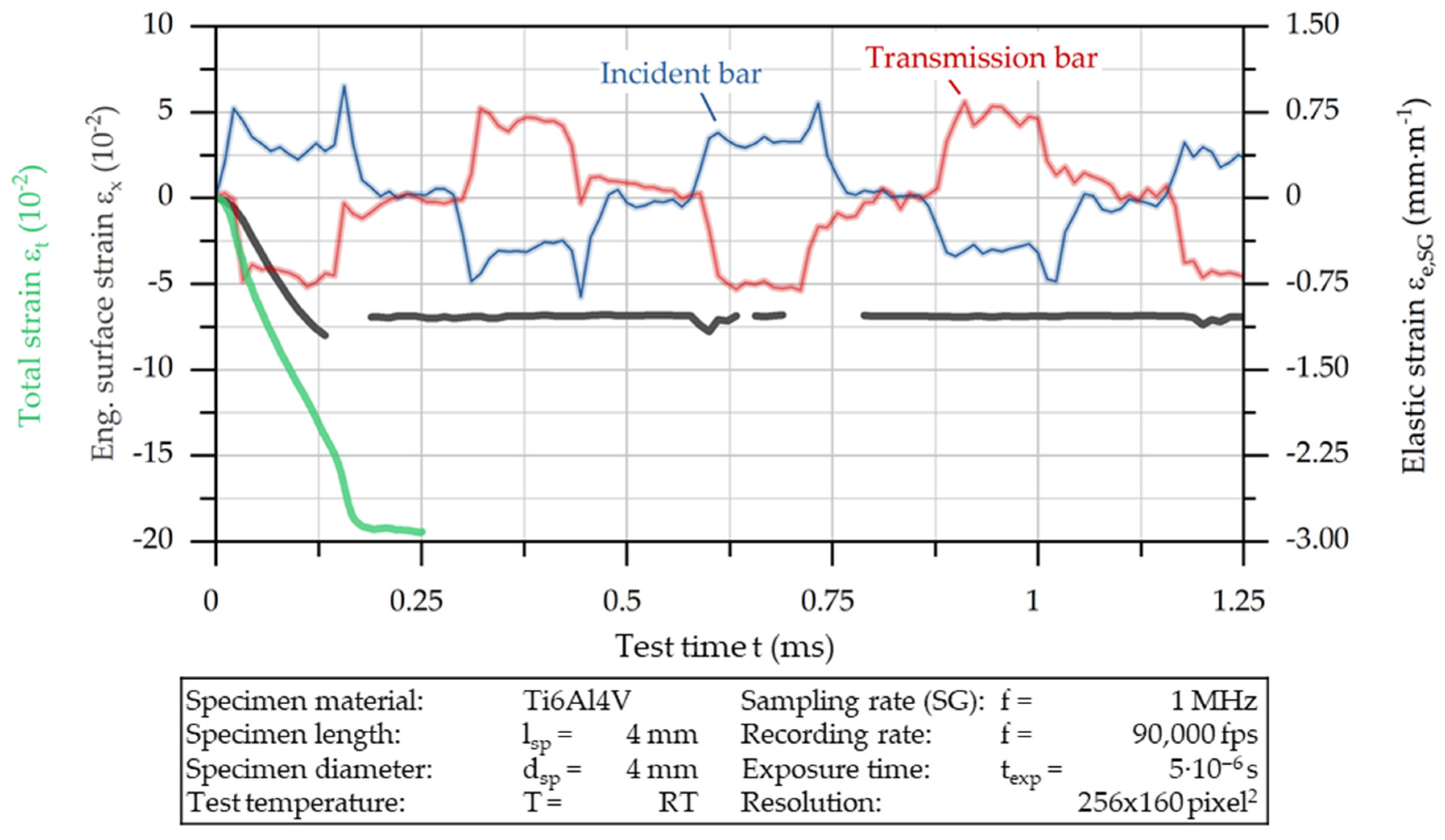
The first test on Ti6AlV4 with the named parameters showed that the chosen integration and exposure times would not fit the high strain rates occurring at the specimen’s surface, so motion blur occurred on the recordings (
Figure 5a). This necessitated further adjustments to the camera settings. Subsequently, the light output was increased using four light projectors, which were positioned along the radial direction of the specimen. In doing so, the exposure time was reduced to t
exp,2 = 5·10
−6 s, simultaneously increasing the recording rate to f
2 = 90,000 s
−1 and further reducing the resolution to 256 × 160 pixel. However, the frame still included the whole specimen geometry (
Figure 5b). It is apparent that the optimization of the camera parameters results in significantly less pronounced motion blur.
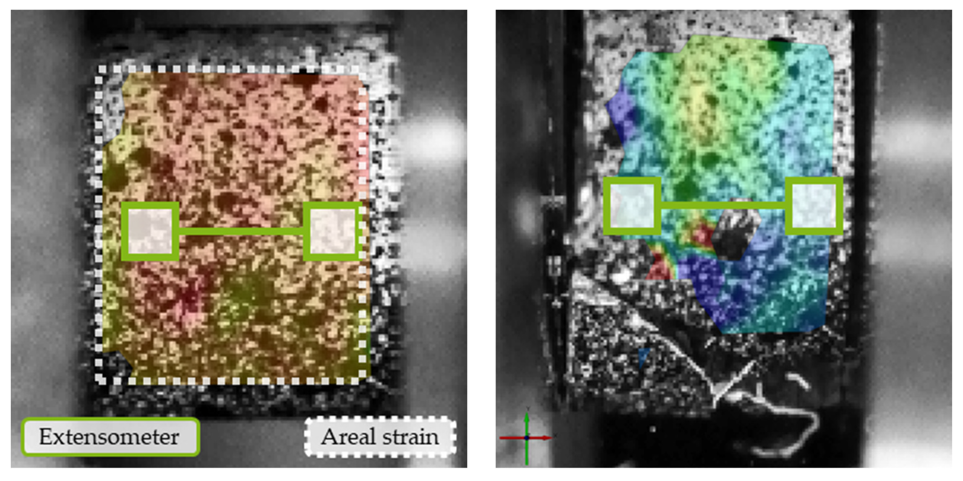
In order to define the camera system’s accuracy, eleven recordings were taken of the specimen in an undeformed initial state. The subsequent DIC analysis was evaluated regarding the maximum deviation in the engineering surface strain ε
x and length change Δl
x. The evaluation was conducted on the one hand by using the arithmetic mean strain of the entire visible specimen’s surface, and, on the other hand, by means of a digital extensometer, which was positioned in the center of the specimen (
Figure 6). In order to establish a testing strategy under authentic and application-oriented conditions, the measurement was carried out with the optimized parameters as described above.
The evaluated maximum deviations of the eleven pictures are shown in
Figure 7. Since the first picture is referred to as the initial state (reference), the value for both strain and length change is zero. The following data points show deviations in relation to the first picture, while the mentioned value is the difference in the maximum deviations in positive and negative directions. This means there is no need for a particular reference point for this measurement, as the difference remains unchanged.
Figure 7a shows the absolute strain differences in the eleven measurements. It can be seen that the maximum deviation of the extensometer measurement is roughly double the areal strain calculation. The same difference in areal and extensometer strain measurements can be seen from the length change (
Figure 7b). Nevertheless, the maximum deviation of 9 μm is low, considering the resolution of 39 μm per pixel in this test setup.
From previous investigations, the maximum strain in the tests is expected to be approx. 20%, so the relative deviation is about 0.16% for extensometer and 0.075% for areal strain measurements. However, this method presents the accuracy of the measurement in the initial state of the specimen and thus does not include any changes in pattern quality due to deformation.
With respect to the material behavior in SHPB tests, the extensometer measurement is applied, regardless of the better results for areal strain measurement in previous investigations, since it has been proven to be less vulnerable to high deformations and thus to artefacts occurring on the specimen’s surface (
Figure 6b).
3.1. AISI 1045 Specimens
To illustrate the procedure for evaluating the data,
Figure 8 shows the time course of the elastic strains in the bars of the SHPB and the course of the plastic strain in the AISI 1045 (C45, 1.0503) steel specimen calculated from them (green line) and the strain calculated with point tracking (black line). At a glance, it is clear that, according to the assumption behind the SHPB principle, the plastic compression of the sample takes place during the first pulse pass. From the stochastic pattern, it can be seen that elastoplastic post-deformation occurs after the reflection of the pulse at the bar’s ends (t = 0.6 ms). The main focus of the diagram (
Figure 8) is the comparison of the development of plastic strains. A more detailed analysis can be undertaken with the help of
Figure 9, which does not include a representation of the elastic bar strain.
Figure 9 shows the strain curves supplemented by a plot of the strains measured at six different times. Frame (i) shows the initial state of the specimen. Frames (ii) and (iii) illustrate the plastic deformation during the actual test. Finally, frames (iv) to (vi) depict the elastoplastic post-deformation after the actual test, resulting from the reflected pulse. The strain distributions show that a homogeneous strain state exists both during deformation and in the final state of the specimen. It should be noted that the upper and lower visible edge areas of the specimen are not added to the evaluation since they are not aligned with the camera optics due to their cylindrical shape. Overall, the curves of strain gauges and DIC do not differ much, proving that the assumptions used for calculating the strain by strain gauges provide valid results. Moreover, the maximum strain measured by both methods, which depends on the kinetic energy of the projectile, corresponds with works from the literature for AISI 1045 [
28,
29].
However, there is a limitation: the strain gauges record an increase in strain over a longer period than DIC. This results in a maximum value of ε
t ≈ −22%, while DIC calculates ε
x ≈ −18.5%. This can be attributed to the hysteresis effects that occur in highly dynamic material testing [
6]. Mates et al. found that the deformation rate in SHPB tests of AISI 1045 measured by strain gauges increases up to a strain of ε
t ≈ 5.5% and then stabilizes [
30]. The same behavior can be seen from the green curve in
Figure 9, which has a changing gradient until a strain of ε
t ≈ −4%. In the case of the DIC measurements, this effect does not occur and the strain is linear from the beginning, which aligns with the theoretical assumption.
A further finding regarding the DIC analysis is that the elastoplastic post-deformation of the specimen occurs as a consequence of the pulses being reflected multiple times at the bar ends. The plastic fraction of the first post-deformation is ε
x = −0.46% and for the second one it is ε
x = 0% (
Figure 10). Even though post-deformation can be considered small compared to the initially characterized compression, it must be noted that the specimens only have limited suitability for characterizing the deformation recorded via the strain gauges.
3.2. Ti6Al4V Specimens
In the next step, the flow stress behavior of the titanium alloy Ti6Al4V (3.7165) was characterized using the methods previously described.
Figure 11 shows the related results. Again, six selected strain distributions are shown in addition to the strain–time diagram for the strain gauges and the DIC. Equivalent to
Figure 9, frame (i) shows the initial state of the specimen. In frames (ii) and (iii), the plastic deformation occurring in the actual test procedure are depicted. The second row (frame (iv) to (vi)) illustrates the influence of a reflected impulse after the actual test. The evaluation of the individual strain steps clearly shows the inhomogeneous strain distribution of the titanium alloy, as well as crack initiation. In this case, the crack formed in the lower region of the specimen (marked in green) and led to an interruption in the course of the facet-tracking-based strain measurement. Immediately before crack initiation, local strains in the range of ε
x ≈ −25% were present in the region of subsequent material failure. The magnitude of these strains at failure is consistent with studies in the literature. Chiou et al. were able to determine strains at failure of ε
x ≈ −35% for Ti6Al4V under comparable test conditions [
31], while Ran et al. found a value slightly below ε
x ≈ −20% [
11]. This inhomogeneous deformation behavior causes significant differences in the two strain measurements. While DIC detects non-uniform strain distribution, the strain gauge measurement assumes homogeneous specimen deformation. Therefore, the measurement result is significantly distorted by bulges in the specimen. On the one hand side, the determined compression strain increases faster in the case of the strain gauges; on the other hand, it extends over a longer period, similar to AISI 1045 steel, which is again attributed to the hysteresis effects typical for SHPB. In the case of the Ti6Al4V alloy, the post-deformation due to the reflected pulses is of an exclusively elastic character.
Bulging at the circumference of the specimen, which was observed in particular for Ti6Al4V alloy, was identified as the main mechanism of the inhomogeneous specimen deformation as well as the main reason for non-compliant measurements between the two methods.
Figure 12 compares the bulging of AISI 1045 and Ti6Al4V based on the radii formed. While the radius for AISI 1045 steel is of insignificant magnitude (r = 28 mm) compared to the ideal conditions of an infinite radius, for Ti6Al4V alloy it is r = 17 mm and therefore significantly more bulged. Typically, this bulging is attributed to the friction between the bars of the SHPB and the specimens [
9]. However, in this case, Ti6Al4V is assumed to have comparable or even reduced friction compared to AISI 1045 steel. This behavior is assumed to be more non-uniform compared to AISI 1045 steel, as is clearly observable by comparing
Figure 9 and
Figure 11. It is deduced that, for corresponding materials, alternative methods for the data evaluation of flow stress and damage characterization at SHPB have to be developed.
3.3. Deep Learning
In the following section, the results of the deep learning approach for the characterization of shear bands in the Ti6Al4V-specimen are presented. Despite the limited amount of training data, the network achieves a total dice score of 0.81, with the worst performance from the five-fold-cross validation being 0.77. An example segmentation result from the test data is shown in
Figure 13. In addition to this high performance, given the limited amount of training data, the model was also tested on chips to demonstrate its ability to detect shear surfaces. Although no chip images were used in the training process, the network was able transfers the structures’ features and detect deformed surfaces in the chips (
Figure 14). However, full detection of the sheared surface is still not possible, due to the small amount of training data. Nevertheless, the model’s strong generalization capabilities show its good suitability for further analysis of kinetically similar material deformation. Therefore, deep learning could be used for the transverse analysis of shear specimens in a more general analysis of chips.

 ,
, 


