1. Introduction
Space travel involves dealing with physical, technical, and scientific difficulties; space is a hostile and unfriendly environment without air or gravity and with high levels of ionizing radiation. Our planet, Earth, is surrounded by air composed of nitrogen, oxygen, and other gases, called the atmosphere. Upon entering the atmosphere, the spacecraft experiences drag, which exerts mechanical stress and compression of the air in front of the spacecraft, which in turn causes heating. Good design, such as optimizing the shape of a re-entry spacecraft with considering the amount of heat flux, can reduce the overall mass and cost of a mission and reduce the risk of passenger injury or loss, where applicable.
As also stated in Section 4.1.7 of [
1], and in space operations documents (Returning from Space: Re-entry) published by the Federal Aviation Administration (FAA), all space-mission planning begins with a set of requirements that we must meet to achieve mission objectives. The re-entry phase of a mission is no different, and one must delicately balance three often competing requirements, namely deceleration, heating, and accuracy of landing or impact. Once all trajectory possibilities have been exhausted, one can turn to options for vehicle design, where two ways to meet mission requirements exist, i.e., vehicle size and shape, and thermal protection systems (TPS).
The re-entry vehicle’s size and shape help determine the ballistic coefficient (BC) and the amount of lift it will generate (most re-entry vehicles are considered nonlifting due to the added complexity of lift in the re-entry analysis). The most challenging component of BC to determine for re-entry vehicles is the drag coefficient, CD, which depends mainly on the vehicle’s shape. In addition, it is essential to notice how varying BC changes a re-entry vehicle’s deceleration profile and affects the maximum heating rate.
A more streamlined (high-BC) vehicle reaches maximum deceleration much lower in the atmosphere than a blunt (low-BC) vehicle (i.e., effects of vehicle shape), and the atmosphere can also significantly decrease re-entry accuracy. Therefore, the designers want the vehicle to spend as little time in the atmosphere as possible, which makes a streamlined vehicle desirable for better accuracy, even though one must accept more severe heating rates. Thermal protection systems can deal with this heating. Effects of vehicle shape on the re-entry corridor are also another factor to be considered as the corridor’s upper or overshoot boundary depends on the minimum deceleration for atmospheric capture [
1].
The spacecraft optimization design involves a variety of disciplines, including aerodynamics, aerothermodynamics, guidance and control, structure, and cost. Considering the difficulties in its progress, it has been evident from the start that the design of such systems requires a compromise between numerous domains of knowledge. Many efforts have been made in this area, the most recent of which are summarized and briefly discussed in the following section.
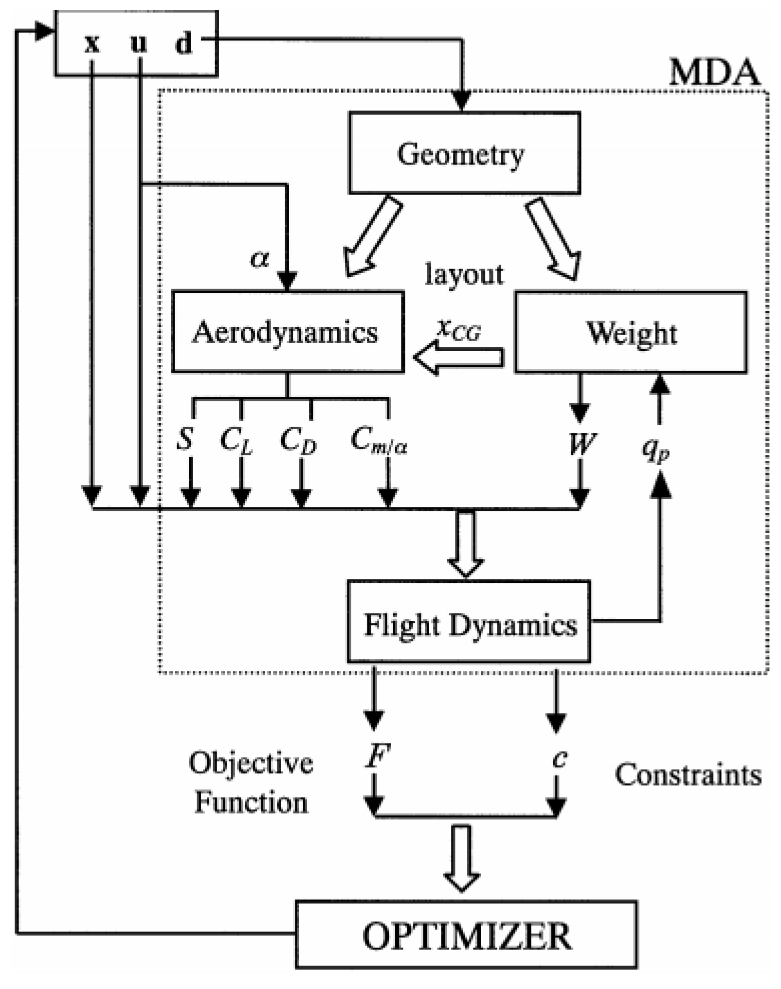
The problem of re-entry spacecraft shape optimization has been addressed in several publications. The multidisciplinary optimization of re-entry spacecraft has been discussed by Tava and Suzuki [
2], considering four crucial disciplines, namely geometric shape, weight, aerodynamics and flight dynamics, and their block diagram is shown in
Figure 1. The authors accentuated on the complexity of the disciplines and their conflicts; however, less emphasis was made on their optimization method, the accuracy of modeling the disciplines, and their chosen approach—multidisciplinary design feasibility (MDF), a time-consuming and costly method.
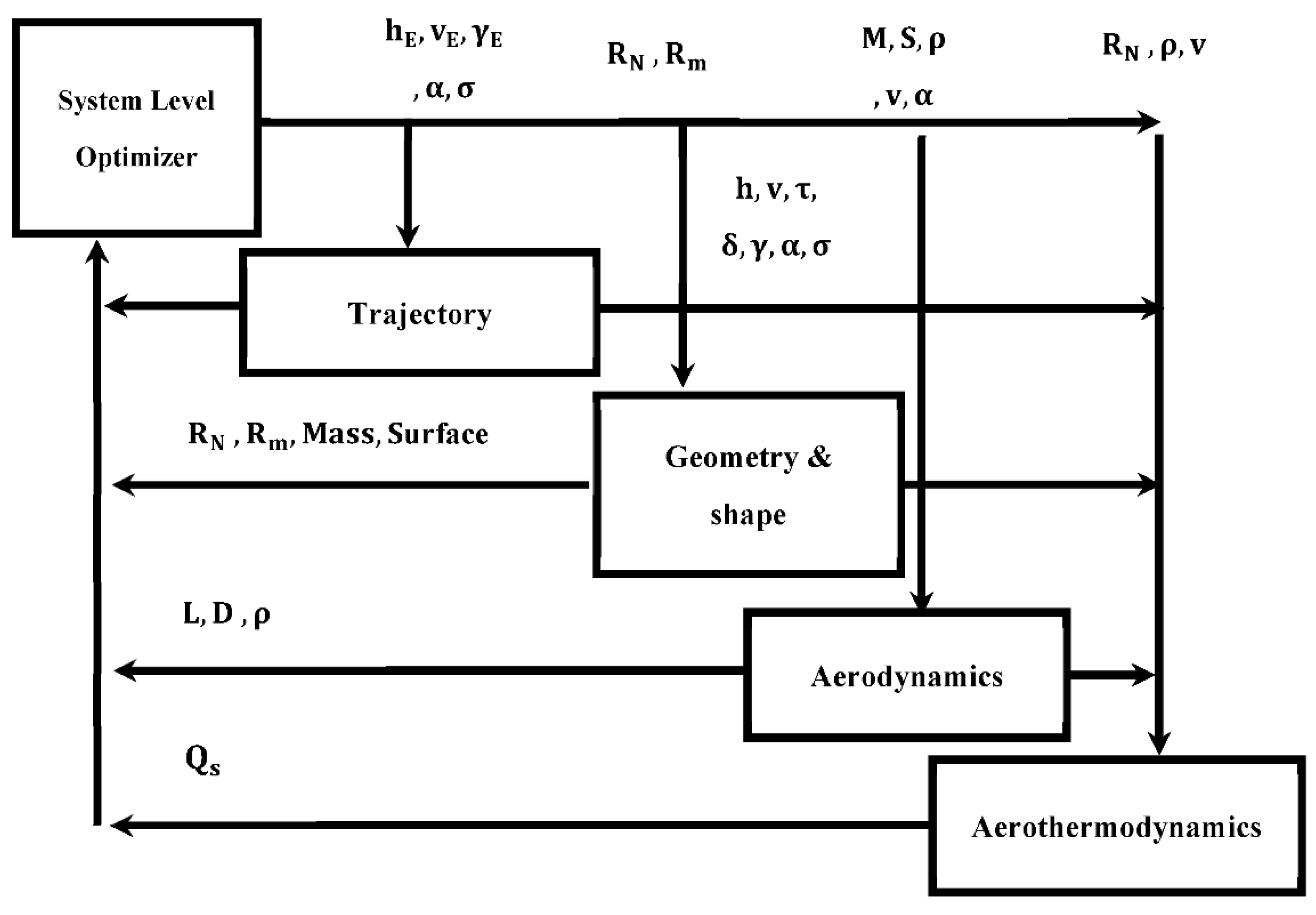
Mor and Livne [
3] investigated the trajectory and the thermal protection system (TPS) for a flight vehicle using the multidisciplinary optimization method. The article highlighted the interdisciplinarity of disciplines and their conflicts (their achieved model is shown in
Figure 2 for reference).
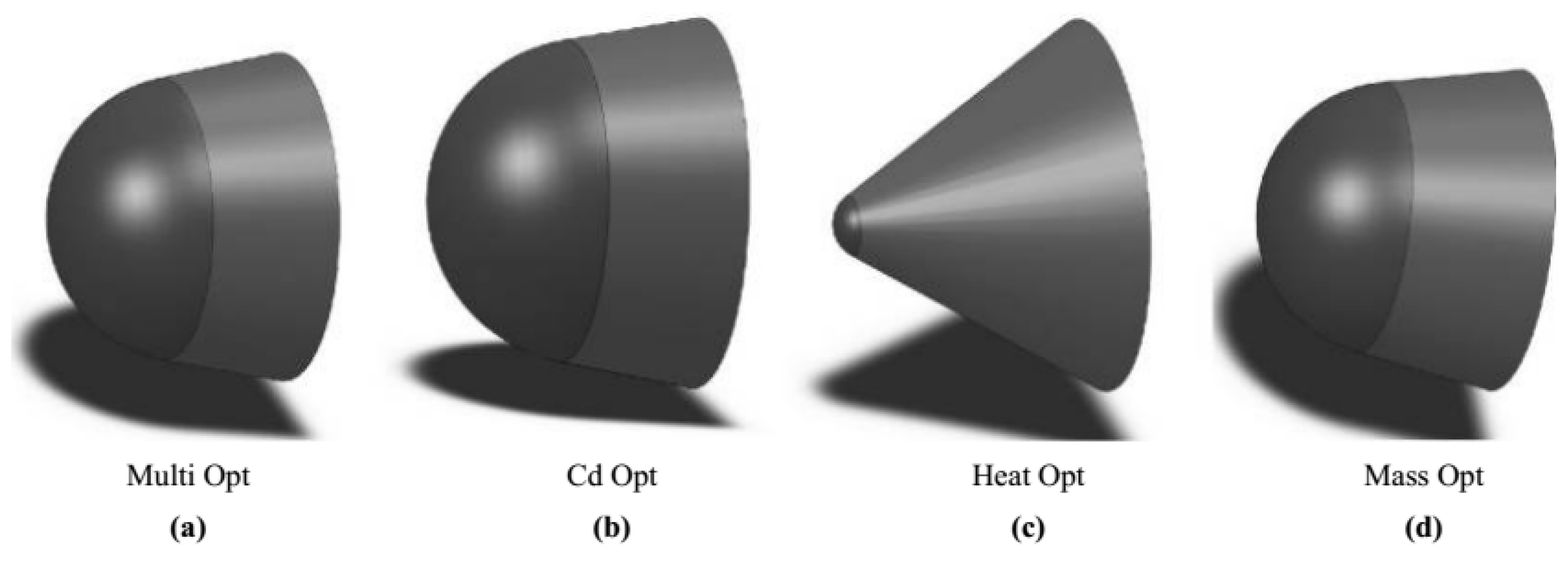
The MDO of a re-entry capsule was presented by Nosratollahi et al. [
4], with structure, aerodynamics, and aerothermodynamics modules in place. The authors compared their results using two optimization methods: the multiobjective optimization method and a new optimization approach based on a genetic algorithm. The objective function used in [
4] is the mass reduction of the entire system in terms of aerothermodynamics and aerodynamics constraints. Finally, several nose-shape designs were achieved by increasing the weight of each module and adjusting their factor of importance in optimization (
Figure 3).
Nosratollahi et al. [
5] proposed an optimized design of the aerodynamic structure for a capsule to reduce the heat absorption and drag coefficient. They proposed a feasible region so that the designer can decide without having to solve the problem to find the best solution. Later, Adami et al. [
6] performed the optimum design of the aerodynamic structure for the same capsule presented by Nosratollahi et al. [
5], where they added the structure’s discipline, simultaneous minimization of drag coefficient, heat absorption, and mass in their model. Like in the previous work, Adami et al. [
6] used the search method to perform the optimization of the design. Later, Nosratollahi et al. [
7] provided the optimized design of a controllable re-entry capsule using a multidisciplinary optimization and search method, where the minimum landing speed and minimum mass were selected as the objective function. The MDO of a manned capsule was also addressed by Adami et al. [
8], considering the geometric shape and re-entry trajectory, with the criterion of minimizing the vehicle’s mass and adhering to the heat flux, aerodynamic, structural, and flight path constraints, frequently observed in the all-at-once (AAO) method.
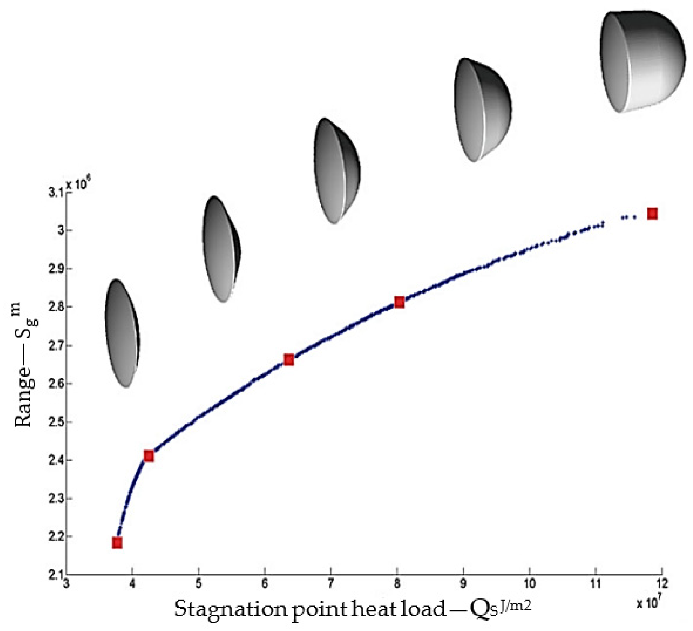
In the book by Dirkx and Mooij [
9], multidisciplinary optimization methodology was established and applied to the shape optimization of two classes of re-entry vehicles: a low lift-over-drag or blunt capsule (such as the Apollo); and a winged vehicle, such as the Space Shuttle. The emphasis is put on cubic Hermite splines and spline surfaces when using the multiobjective particle swarm optimization (MOPSO) algorithm. The presented method was reported to take 1 h to optimize the capsule-shaped vehicles. Capsule shapes with different dimensions are achieved with different ranges by changing the stagnation point heat load constraint (
Figure 4).
The re-entry trajectory optimization problem for hypersonic vehicles in this paper has been studied recently by Yu et al. [
10]. The authors indicate that two drawbacks exist to this topic. Firstly, there is no consideration for navigation errors caused by blackout zones in re-entry trajectory optimization models. Second, a solitary methodology is regularly applied to enhance the re-entry trajectory, which neglects to cover its deficiency by consolidating it with different approaches. To this end, a hybrid particle swarm optimization (PSO)–Gauss pseudo-method (GPM) algorithm, specifically the mixed PSO-GPM calculation, is proposed to optimize the re-entry trajectory in this paper. The authors suggested combining other metaheuristic algorithms and pseudospectral methods to solve more complicated optimization problems.
Upon completion of the review of several articles on re-entry spacecraft presented in the previous section, in what follows, the MDO of a re-entry spacecraft or a space capsule is implemented in a combined and innovative method. The all-at-once (AAO) approach to the MDO of a re-entry capsule-shape spacecraft with a low lift-to-drag ratio (L/D) is achieved using the RPM optimization method, where a semiballistic trajectory, considering the geometry and shape, aerodynamics, and aerothermodynamics disciplines are used. Considering variables, constraints, and various parameters and maximizing the re-entry spacecraft’s cross-range as the objective function, the optimized dimensions leading to the reduction in the mass of the capsule are achieved and presented. The MDO method is validated using the available data for the Apollo re-entry capsule. The optimal solution is reached through several iterations to ensure that optimality conditions are satisfied. It is found that the mass of the optimal capsule generated using the proposed method is more than 17% lower than Apollo’s. To the author’s best knowledge, the application of the AAO-RPM approach to the MDO of a re-entry capsule-shape spacecraft has not been reported in the open literature, which could be considered the main contribution of this paper.
The structure of the paper is as follows:
Section 2 presents the Methodology, where the Problem Architecture and Optimization Method, are presented in
Section 2.1 and
Section 2.2, respectively.
Section 3 presents the Modeling Approach, where Modeling (
Section 3.1), Boundary Condition and Constraints (
Section 3.2), and Objective (
Section 3.3) are presented. In
Section 4, the results and a discussion of them are provided, followed by final conclusions summarizing the most important achievements of the presented work.
3. Modeling Approach
3.1. Modeling
The trajectory and the shape of a capsule or a reusable spacecraft are affected by many disciplines such as trajectory (equations of motion), aerodynamics, and vehicle heat transfer, which will be discussed in the following sections. In brief, there are three types of re-entry trajectories: ballistic, semiballistic, and maneuverable trajectory, in which control and guidance of the vehicle are different in aerodynamic force that is related to lift-to-drag ratio (L/D) and active control force.
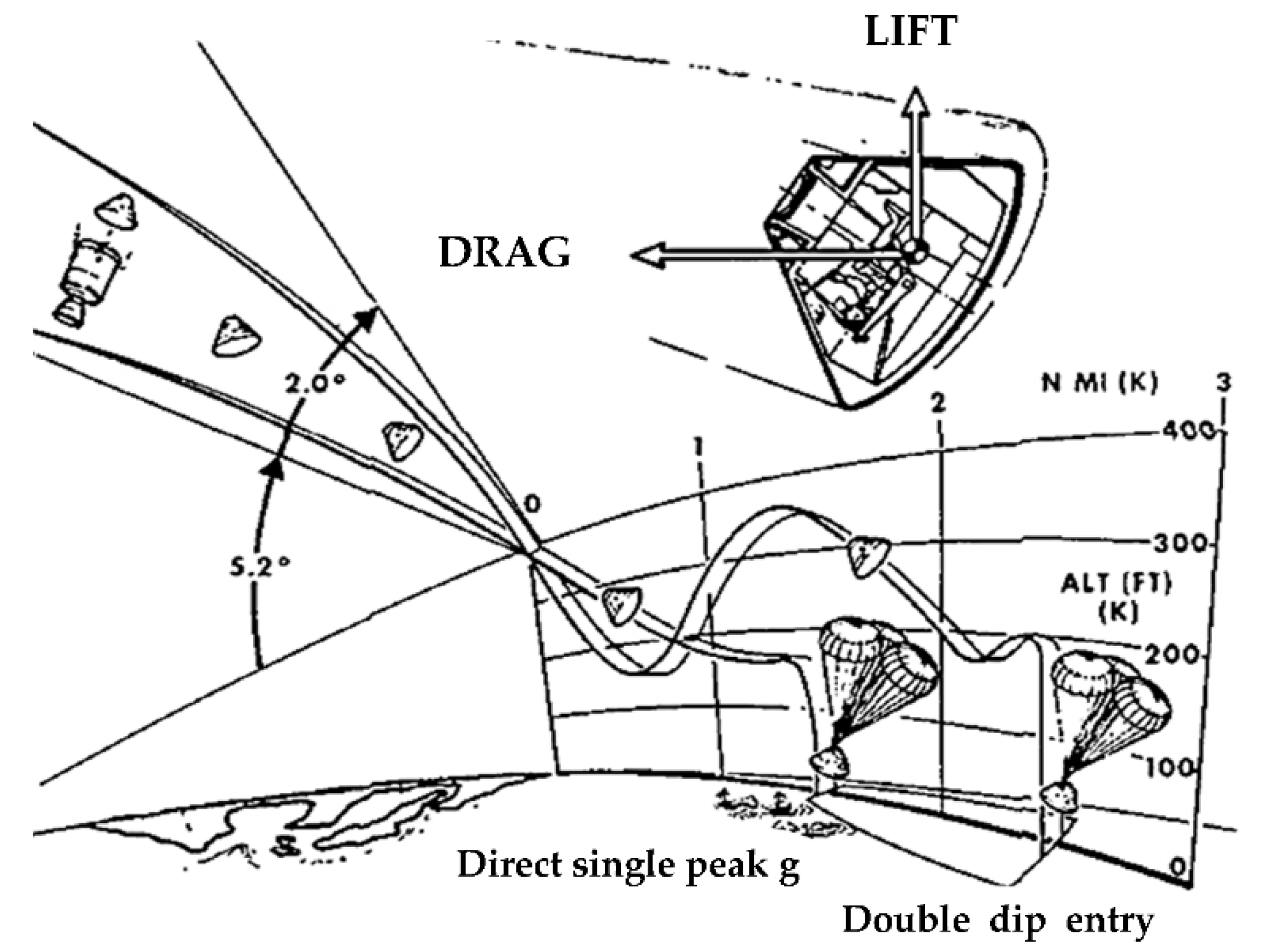
A semiballistic trajectory is a class of spacecraft guidance and re-entry trajectories that extend the range of suborbital spaceplanes and re-entry vehicles by employing aerodynamic lift in the high upper atmosphere. A series of skips allows the range to be further extended and leads to the alternate terms skip-glide and skip re-entry (see
Figure 7 [
16] for Apollo capsule skip re-entry).
The earth has been assumed to be a perfect, nonrotating sphere. The acceleration due to gravity is given by Newton’s inverse square law [
17]. The density variation with altitude is assumed to be exponential and given by the relation:
- B.
Aerodynamic Model
All defined design variables are affected by the aerodynamic optimization process. The objective of the aerodynamic design process is to generate a ballistic coefficient and lift-to-drag ratio (L/D) that is optimal for the aerothermodynamics and trajectory disciplines, respectively.
Forces affecting re-entry of a spacecraft include gravitational potential, drag, and lift. The initial guess of lift, drag, and slip coefficients uses parameterization of a parabolic surface. The drag coefficient is used to determine drag force. Assuming a ballistic case, the predominant force impacting the aerodynamics of a capsule re-entry is a drag. A good metric to compare aerodynamics of various shape designs is the ballistic coefficient, defined according to drag coefficient, mass, and surface area.
With feedback from trajectory and aerothermodynamics disciplines, the aerodynamic discipline will vary drag coefficient by changing design geometry to generate more optimal solutions. Initial shape parameters of the Apollo 11 re-entry capsule will be used [
4,
16]:
CL0 = 0.0005,
CL1 = −0.0176,
CD0 = 0.0262,
CD1 = 0.0059,
CD2 = −0.0145.
- C.
Equations of Motion
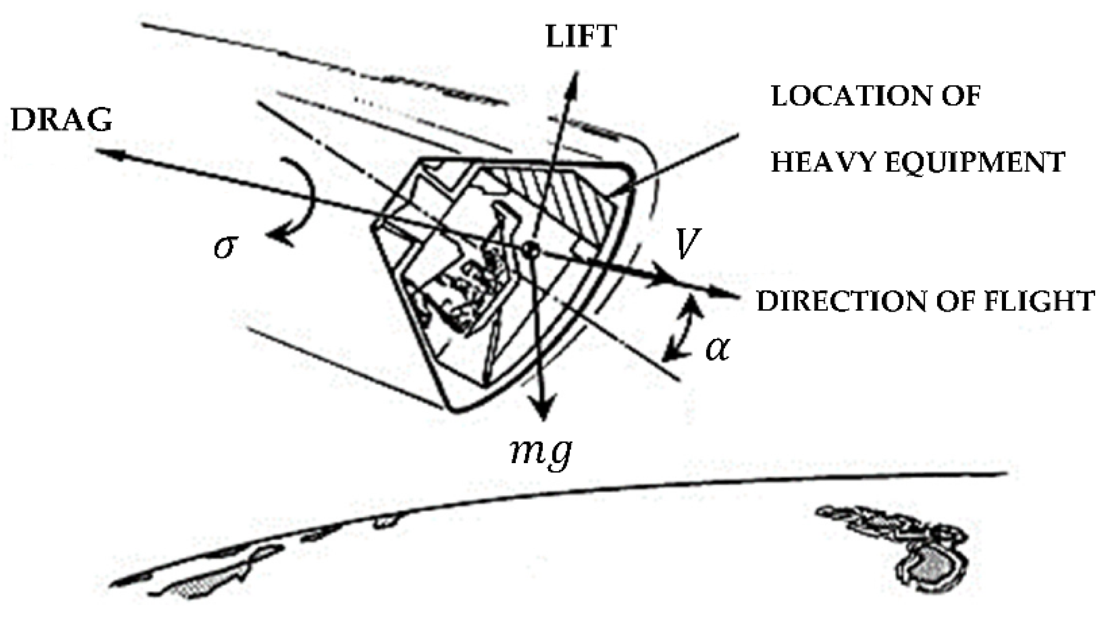
In this section, the equations of motion are used to determine the trajectory of the re-entry spacecraft are described. First, the reference frame used in the computations is wind or velocity axis system. The resulting equations of motion in spherical coordinates for a re-entry problem will then be discussed. If the summation of all the forces shown in
Figure 8 is presented in the wind frame, the six state equations of vehicle mass center are [
17]:
where the trajectory parameters are:
r: Altitude;
ϕ: Longitude;
θ: Latitude;
α: Angle of attack;
v: Velocity;
γ: Flightpath angle;
ψ: Azimuth;
σ: Bank angle.
- D.
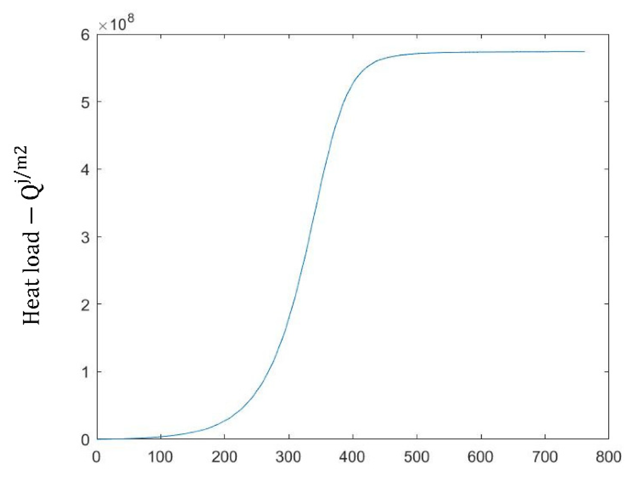
Stagnation Point Heat Rate
High heat fluxes are experienced during re-entry as a result of the hypersonic velocity, which presents a significant design challenge. To evaluate the performance of a re-entry vehicle, a model for its aerothermodynamic performance is needed. Some conceptual design tools can be used to estimate the heat transfer to critical areas of the vehicle. As also stated by Cavallero [
18], the radiation is negligible for entry velocity below 9 km/s and hence is not included in the evaluation. The stagnation-point heating rate is modeled by using Equation (10), as given in the book by Dirkx and Mooij [
17], which gives the heat load during the re-entry phase:
- E.
Dynamic Pressure Constraint
Maximum load factor n
tot, which is the maximum total aerodynamic deceleration experienced by the capsule, is determined from the following Equation [
16]:
The aerodynamic coefficients vary only marginally over the trajectory of a capsule. This, along with the form of Equation (11), leads to the fact that the point of maximum load factor will be very close to the point of maximum dynamic pressure
qdyn. For this reason, considering the
qdyn constraint separately for capsule-shaped vehicles is unnecessary [
17].
- F.
Controls
For the capsule, an ideal guidance and control system is used so that the commanded attitude angles (α, σ) are assumed to be achieved instantaneously by the vehicle [
17].
- G.
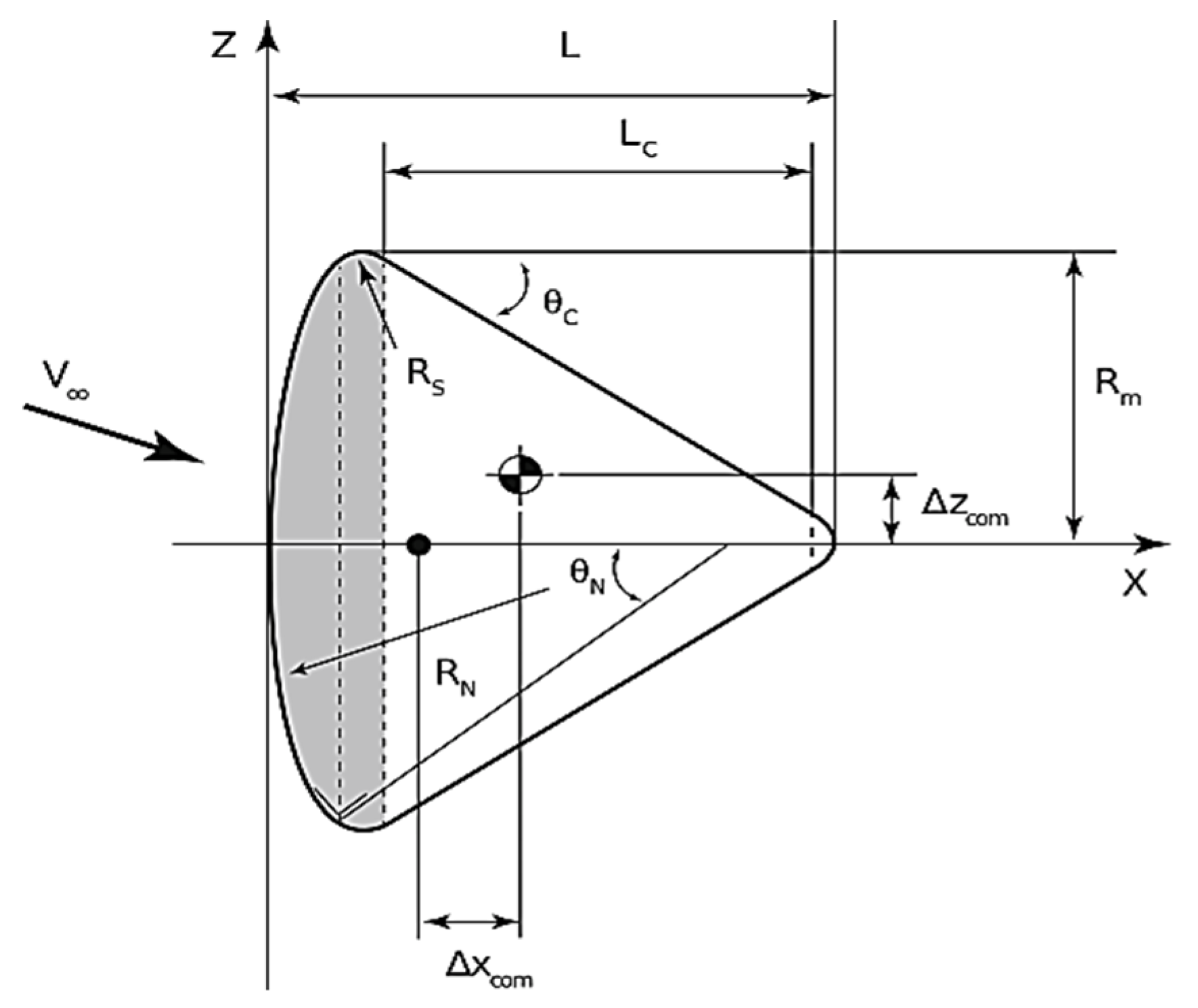
Capsule Geometry and Properties
Listed below are the capsule geometric parameters that will be varied. These parameters are selected due to their significant impact on the objective function [
20].
RN: Nose radius;
Rm: Mean radius;
RS: Corner radius;
M: Structure mass;
θN: Nose angle;
LC: Cone length.
The above parameters are described in the schematic in
Figure 9. Other geometric parameters are computed as a function of the selected design variables. Therefore, they are not considered independent variables.
Apollo capsule is the reference of the geometry for use in geometric relations, so the mass of the capsule will be determined with this equation:
. Therefore, there is a geometry proportion between this sample and Apollo geometry, except for R
S; because of heat flux in corners, R
S should be limited with Equation (13). This method generates an error, but the authors of [
9] did not offer a solution to address this.
3.2. Boundary Condition and Constraints
Boundary conditions and constraints on states, controls, and geometry parameters are stated as follows:
Latitude = 0 deg, Longitude = 0 deg
Altitude = 120 km, Speed = 7.830 km/s
Azimuth = 90 deg, Flightpath angle = −2 deg
Latitude = 30 deg, Longitude = 90 deg
Altitude = 5 km, Speed = 250 m/s
Azimuth = −10 deg, Flightpath angle = −2 deg
−30 deg < Angle of attack α < 30 deg
−90 deg < Bank angle σ < 90 deg
3m < RN < 7m
0.5m < Rm < 3m
3.3. Objective Functions
The objective is determined to find the control variables, angle-of-attack, and bank angle deflections that would maximize the re-entry vehicle’s crossrange and indirectly reduce the heat flux and the mass. Maximizing crossrange would be the same as maximizing the latitude at the final time when the re-entry occurs along the equatorial line [
17]. The problem is a Mayers problem and can be represented as:
4. Results and Discussion
In the present study, the optimal solutions to the MDO problem, considering a re-entry vehicle with a lift-to-drag ratio (L/D) similar to Apollo, were achieved using an RPM approach and around 300 iterations. The problem consists of finding the optimal RN and control variables during the re-entry period [0,tf] that minimize the objective function Equation (14) subject to the six state differential Equations (4)–(9) and the derivatives of the control variables, the path constraints, and the boundary conditions described above.
The capsule configuration is assumed to be subjected to the heat load constraint, the entry speed of 7.830 km/s, the entry angle of attack of −2 degrees.
Table 1 shows the properties of the optimal shape achieved alongside those reported for Apollo. As can be seen from
Table 1, the mass of the capsule achieved through the presented method is found to be over 17% less than Apollo, and optimal R
N and R
m are also tabulated.
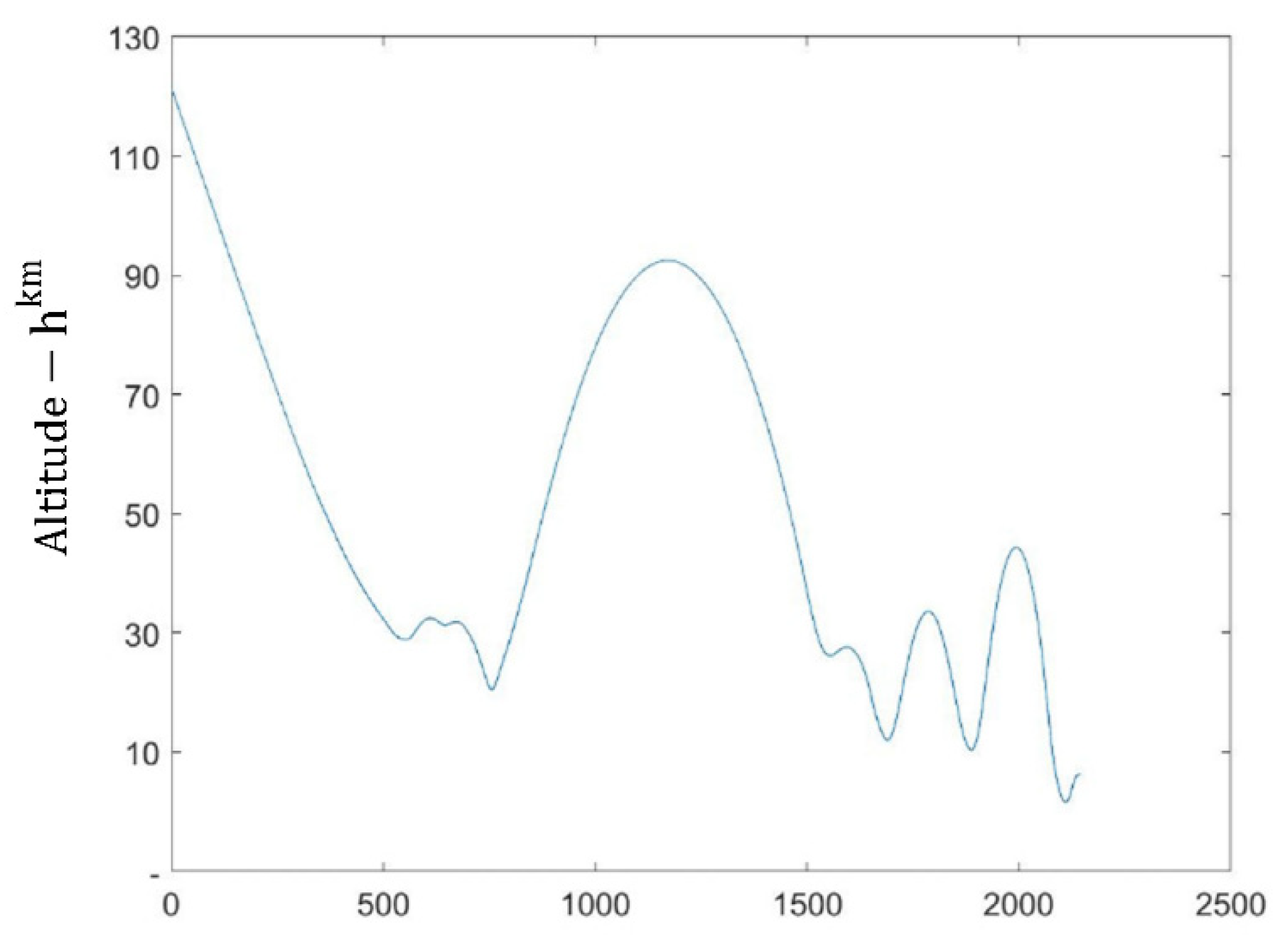
Figure 10 shows trajectory results obtained through the optimization process without enforcing dynamic pressure constraint. As seen from this figure, several large skips are observed, indicating that this is an infeasible solution. In contrast,
Figure 11 shows trajectory results obtained through the optimization process while dynamic pressure constraint is enforced. As can be observed, this figure does not exhibit any large skips, meaning none of the flight path constraints are violated. The same trend is observed in all results achieved through the optimization process, which indicates the robustness of the method used.
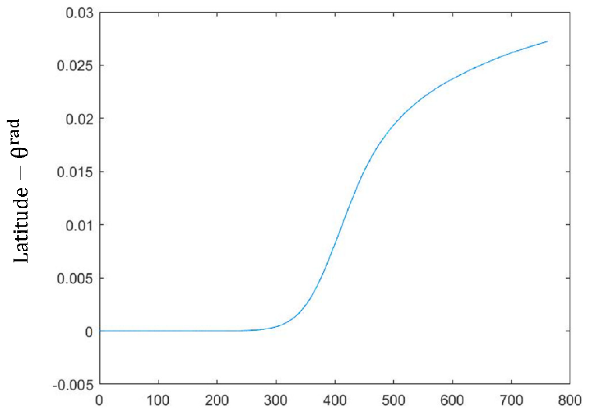
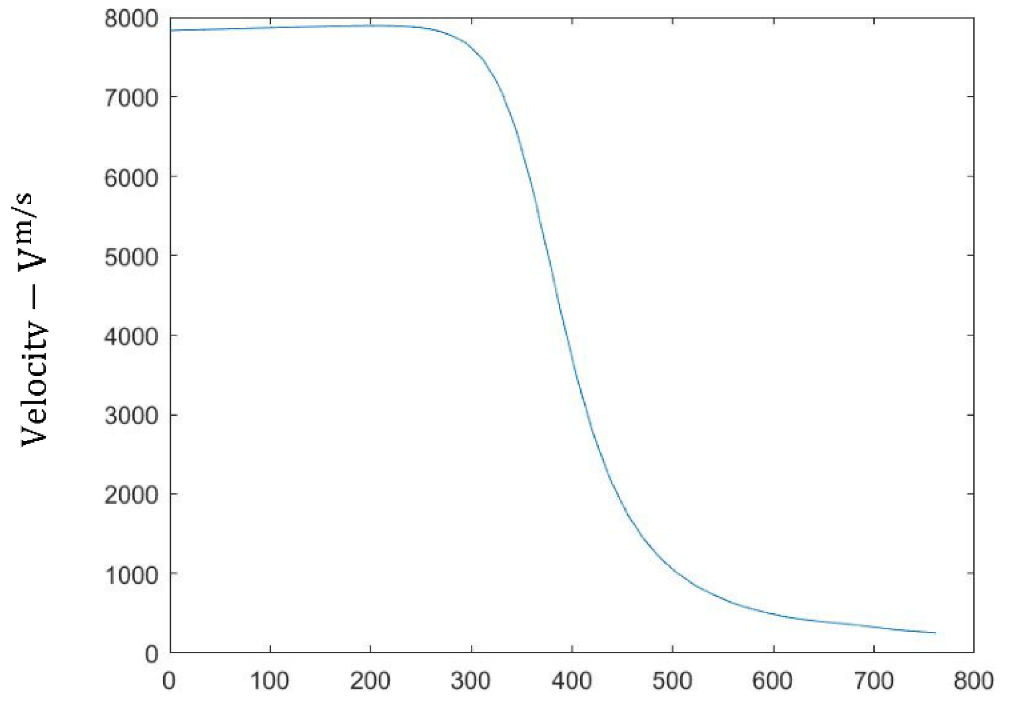
Figure 11,
Figure 12 and
Figure 13 show variations of state variables (altitude, latitude, and velocity, respectively) vs. time. Comparing
Figure 11 to the existing Apollo re-entry data showed the validation of the code developed by the authors where the optimal solution is achieved while all the optimality conditions are satisfied.
Figure 14 shows heat load vs. time, and indicates that it does not exceed the heat load constraint.
Figure 15 shows the control variable (angle of attack) variation vs. time, to generate this trajectory. As can be observed from these figures, the presented method exhibits a reasonable performance in solving such problems.
5. Conclusions
In this paper, the shape optimization of a capsule re-entry spacecraft was reexamined. The problem statement was to minimize the mass on a re-entry spacecraft by changing the shape and the flight path parameters, while satisfying constraints, including critical heat flux, load factor, stability requirements, the flight path, and the shape at the given payload, initial and final flight conditions. A combined and innovative MDO based on the Radau pseudospectral method (RPM), including the key subsystems in the process, is presented. Considering variables, constraints, and various parameters applied through several geometric shapes in the conceptual design phase, the optimized dimensions for a re-entry spacecraft are presented. Considering a vehicle with the same area of Apollo, a 17% mass saving was achieved. In this method, fast computing and simplified models are used together to analyze a wide range of vehicle shapes and entry types during conceptual design.
In the future, other factors such as corner radius, affecting the shape design, and others not included in the present study, can be considered to establish a more accurate geometry of the shape model. Moreover, improved aerodynamic and aerothermodynamic models can be developed to enhance the performance of the optimal solution.


