Abstract
Spin-orbital interaction of light attracts much attention in nanophotonics opening new horizons for modern optical systems and devices. The photonic spin Hall effect or Imbert-Fedorov shift takes a special place among the variety of spin-orbital interaction phenomena. It exhibits as a polarization-dependent transverse light shift usually observed in specular scattering of light at interfaces with anisotropic materials. Nevertheless, the effect of the polarization mixing caused by anisotropy on the Imbert-Fedorov shift is commonly underestimated. In this work, we demonstrate that polarization mixing contribution cannot be ignored for a broad range of optical systems. In particular, we show the dominant influence of the mixing term over the standard one for the polarized optical beam incident at a quarter-wave plate within the paraxial approximation. Moreover, our study reveals a novel contribution with extraordinary polarization dependence not observable within the simplified approach. We believe that these results advance the understanding of photonic spin Hall effect and open new opportunities for spin-dependent optical phenomena.
1. Introduction
Light, as well as mechanical objects, possesses three fundamental constants of motion associated with special symmetry conditions (namely, homogeneity of time, homogeneity and isotropy of space) and commuting with the Hamiltonian under the Poisson brackets—energy, momentum, and angular momentum [1]. Energy of light is the most commonly estimated value discovered in the modern era of photodiodes, phototransistors, and solar cells through the photoelectric effect. Light momentum associated with the Poynting vector can be transferred to the surface under illumination resulting in radiation pressure that was predicted by J. C. Maxwell [2], and firstly demonstrated by P. Lebedev [3] and independently by E. Nichols and G. Hull [4] in 1901. The first insights on angular momentum of light were conducted by J. Poynting in 1909 [5], who had drawn a parallel between a revolving shaft and a circularly polarized optical beam. However, the real splash of interest to optical angular momentum was followed by L. Allen et al. [6] discovering the orbital angular momentum for Laguerre-Gaussian beams. For paraxial optical beams, the total angular momentum represents the sum of two contributions—the spin and orbital parts. Spin-orbital interactions of light lead to a number of phenomena and applications including spin-dependent effects such as optical beam shifts and spin-Hall effects in inhomogeneous media and at optical interfaces [7], spin-controlled light manipulation using anisotropic and chiral structures as converters and generators [8], robust spin-directional coupling resulting in the transverse [7,9,10] and longitudinal [11] spin angular momentum of the surface plasmon-polariton.
Another appealing feature related to spin-orbit interactions is the shifts of optical beams. Here, we focus on the ‘Imbert-Fedorov’ (IF) shifts meaning that the planes of incident and reflected or transmitted light beams differ. This kind of a transverse shift was theoretically predicted by F. Fedorov in 1955 [12] and experimentally observed by C. Imbert in 1972 [13]. Complete theoretical description of reflection and refraction of a Gaussian beam at the interface between two media obeying the total angular momentum conservation was proposed by K. Bliokh and Y. Bliokh [14] and then experimentally verified by O. Hosten and P. Kwiat via the quantum week measurements concept in 2008 [15]. Generally, IF shifts could be observed for any polarization of incident light. However, the most attractive case, called ‘photonic spin Hall effect’ (PSHE), is observed under circularly polarized beam illumination. PSHE may offer potential applications in various spin-dependent optical components including beam splitters [16,17] and surface sensing [18,19]. The PSHE enhancement was demonstrated for different anisotropic materials and structures including uniaxial crystals [20,21], polarizers [22], polymer films [23], liquid crystals [24], metasurfaces [16,25,26,27,28], hyperbolic metamaterials [29,30,31], etc.
Nevertheless, despite a plethora of works regarding IF shifts and PSHE with different structures and interfaces, the influence of anisotropy on the PSHE has not been studied consistently. It is well-known that an anisotropic medium leads to polarization mixing (PM) between TE (s) and TM (p) polarizations resulting in non-zero cross-polarization TE-TM Fresnel coefficients. Thus, the total Fresnel matrix demonstrates both conventional purely polarized TE and TM contributions and , and off-diagonal polarization mixing terms and :
Here, are the reflection (transmission) amplitudes, where the first and second indices mean the polarization of incident and reflected (transmitted) waves, respectively. Index denotes the reflected and transmitted beam, respectively. The detailed derivation procedure of Fresnel coefficients is provided in Appendix A. Obviously, the PM terms are zero () for the case, when the optical axis of the uniaxial crystal lies in the plane of the interface parallel or perpendicular to the plane of incidence of a plane wave (see Figure 2). However, even in this simple case, the optical beam formed by a set of different plane waves with slightly different wavevectors and angles of incidence , possesses the PM contribution. To the best of our knowledge, most of the studies about IF shifts and PSHE in anisotropic systems have not taken the PM terms into accounts and missed an additional contribution to PSHE, which may be significant for some systems.
In this work, for the first time, we derive the analytical formulas for linear and angular IF shifts of light beams in paraxial approximation revealing an additional contribution to IF shift appeared due to polarization mixing. We demonstrate the cases whereas the PM terms dominate over the conventional ones resulting in opposite physical effects. For instance, the IF shift to the left according to standard definition could be indeed the shift to the right by taking into account the PM terms. Finally, we analyze the dependence of the PM contribution on the anisotropy degree. We believe these results will complement the modern theory of optical beam shifts and will significantly enrich their application areas.
2. Account on Polarization Mixing Contribution
We follow the theoretical formalism developed in Ref. [32] for calculation of linear and angular IF shifts by introducing the Fresnel matrix (1) taking into account the off-diagonal PM terms. We derive the Fresnel tensor relating the incident and secondary fields in the beam coordinate frame:
where specifies the transverse deflection of non-central wavevectors from the incident plane. The derivation procedure of Fresnel’s tensor (2) is provided in Appendix A. It is important to note that additional terms proportional to mixing coefficients result in additional contributions to the IF shifts.
In the following, we set the optical axis in the plane of interface and designate the angle between the optical axis and the beam incidence plane as . Furthermore, we consider two of the most critical cases (Figure 1):
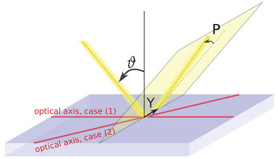
Figure 1.
Geometry of the problem demonstrating schematically the beam incident on uniaxial medium at angle , when optical axis is parallel (case 1) or rotated by an angle with respect to beam incidence plane (case 2). Y and P show the linear and angular IF shifts, respectively.
- (1)
- – propagation along or across optical axis;
- (2)
- – maximum mixing occurs.
The transverse linear () and angular () beam shifts are calculated as the expectation values of the coordinate and momentum operators, respectively:
where is the out-of-plane wavevector component of a plane wave in the beam coordinate frame, is the wavevector in free space and is the normalization factor. Normalization factors for cases 1 and 2 are:
Hereinafter, and mean the real and imaginary parts, respectively; are the unit polarization vectors of the incident field; , and are the corresponding Stokes parameters [33], and .
Finally, we derive the standard () and total () IF shifts without and with taking into account the PM term () for both cases. The linear IF shifts are the following:
The angular IF shifts are the following:
where and is the beam waist. One should notice that Equations (7)–(14) are written in the dimensionless form in order to exclude the influence of the incident wavelength for linear and the beam waist for angular IF shifts.
3. Results and Discussion
One should notice that the thickness of the uniaxial crystal slab affects the IF shifts in a usual well-understood way via phase delay and optical path. Here, we demonstrate the impact of the PM contribution on linear and angular IF shifts for a conventional quarter-wave plate (QWP), which is a typical birefringent slab used in optical beam shifts investigation. We assume the ordinary and extraordinary refractive indices are equal to and , respectively, giving the anisotropy degree:
The plate thickness is representing a standard zero-order QWP. Following the previous discussion we consider two cases when the optical axis of the QWP and the beam incidence plane are (1) mutually parallel and (2) at to each other. Finally, we analyze the dependence of PM contribution on the anisotropy degree and demonstrate the importance of our approach on cases where the total result completely contradicts the one obtained without accounting for PM terms.
3.1. Parallel Optical Axis:
In this part, we assume the optical axis of the QWP and in-plane wavevector of the Gaussian beam central wave are parallel. Figure 2 presents the main result of this work and shows the IF shifts with and without taking into account the PM contribution for the linear 45 () and right-handed circular () polarizations of the incident Gaussian beam.
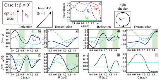
Figure 2.
Case 1: the optical axis of the QWP is parallel to beam incidence plane (). (a) co-polarized (blue and red lines) and cross-polarized (dashed green line) transmittances () for a central plane wave. (b–i) linear (b–e) and angular (f–i) IF shifts in reflection (b,f,d,h) and transmission (c,g,e,i) configurations for the linear at 45 (b,c,f,g) and right-handed circular (d,e,h,i) polarization characterized by the Stokes parameters and , respectively. Dashed cyan and solid blue lines correspond to the standard (Equation (7) for linear and Equation (11) for angular) and total (Equation (10) for linear and Equation (14) for angular) IF shifts, respectively. The total one takes into account the PM contribution (Equation (8) for linear and Equation (12) for angular) shown by the dashed green line. The green regions in subfigures (b,d,e,f,g) mark the areas, where total and standard IF shifts have opposite directions.
The central plane wave does not obviously exhibit the PM contribution (Figure 2a). All other plane waves composing the beam possess extremely small but non-zero PM terms. In the co-polarized case, the integral contribution from the constituent plane waves (except the central one) of the beam is zero due to the mirror symmetry of the problem with respect to the central plane wave. However, it becomes non-zero in the cross-polarized case resulting in additional contributions to linear [Equation (8)] and angular [Equation (12)] IF shifts, shown by the dashed green lines in Figure 2b–i. Surprisingly, these additional PM contributions could be comparable with linear [Equation (7)] and angular [Equation (11)] IF shifts following conventional definition [32], shown by dashed cyan lines in Figure 2b–g. The significant impact of the PM contribution is especially pronounced, when total linear [Equation (10)] and angular [Equation (14)] IF shifts, shown by blue lines in Figure 2b–i, acquire the opposite sign with respect to the standard IF shifts (green regions in Figure 2b,d–g). It means that one will observe the transverse shifts to the right instead of the shifts to the left predicted by the imperfect standard approach or vice versa. Finally, the PM term explains the non-zero angular IF shift under circularly polarized beam illumination impossible under the conventional approach [32], see Figure 2h,i.
The difference between the total and standard linear IF shifts is more pronounced in the reflection configuration. The maximum values of the total linear IF shifts reach for the QWP under consideration. The total angular IF shifts in the same case reach and for linear 45 and circular polarizations, respectively. The absolute values of the total linear IF shifts will be enlarged with stronger anisotropy and bigger thickness of uniaxial medium, while the absolute value of angular IF shift is proportional to beam variance in k-space [34].
Finally, we compare the PM and standard contributions to the IF shift by introducing the PM factor:
This factor shows the PM effect with respect to the standard one passing from for the negligible PM contribution to for the case when PM contribution is determinant. Figure 3 demonstrates the PM factor angular dependence for linear and angular IF shifts with linear 45 polarization. One can notice that in the reflection configuration for both linear and angular IF shifts is for almost any incident angle, while in the transmission configuration it is pronounced mainly for angular IF shifts and for linear IF shifts at large angles of incidence. The results explicitly demonstrate that PM contribution cannot be neglected.
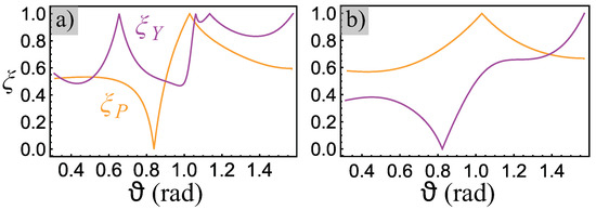
Figure 3.
Polarization mixing factor for linear (magenta line) and angular (orange line) in reflection (a) and transmission (b) configurations. Here, we consider case (1) and assume the linear 45 polarization of a Gaussian beam. Here, and correspond to PM factors for the linear and angular IF shifts, respectively.
3.2. Rotated Optical Axis:
In this part, we assume the optical axis of the QWP is rotated by angle with respect to the in-plane wavevector of the Gaussian beam central wave. Figure 4 shows the IF shifts with and without taking into account the PM contribution for horizontal (), linear 45 (), and right-handed circular () polarizations of the incident Gaussian beam.
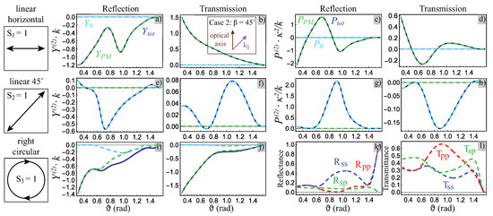
Figure 4.
Case 2: the optical axis of the QWP is rotated at with respect to beam incidence plane, see insert in (b). (a–j) linear (a,b,e,f,i,j) and angular (c,d,g,h) IF shifts in reflection (a,c,e,g,i) and transmission (b,d,f,h,j) configurations for the horizontal (a–d), linear at 45 (e–h) and right-handed circular (i,j) polarizations characterized by the Stokes parameters , and , respectively. Dashed cyan and solid blue lines correspond to the standard (Equation (7) for linear and Equation (11) for angular) and total (Equation (10) for linear and Equation (14) for angular) IF shifts, respectively. The total one takes into account the PM contribution (Equation (9) for linear and Equation (13) for angular) shown by the dashed green line. (k,l) co-polarized (blue and red lines) and cross-polarized (dashed green line) (k) reflectances () and (l) transmittances () for a central plane wave.
In this case, the off-diagonal terms of Fresnel matrix emerge even for the central plane wave (Figure 4k,l). PM brings novel contributions with unconventional polarization dependences. Namely, linear [Equation (10)] and angular [Equation (14)] IF shifts are determined solely by PM contributions [Equations (9) and (13)] under polarization (Figure 4a–d) and by standard contribution [Equations (7) and (11)] under polarization (Figure 4e–h). It is important to note that the contribution proportional to is usually associated not with the Imbert-Fedorov, but rather with the Goos-Hänchen shift. However, a strict analysis shows that even an IF shift is non-zero under this condition due to the polarization mixing in sharp contrast to the standard approach. For polarization, the total IF shift is mainly defined by the PM contribution (Figure 4i,j).
3.3. Dependence on Anisotropy Degree
A comparison between case 1 (, Figure 2) and case 2 (, Figure 4) shows that both linear and angular IF shifts for case 2 are a few times larger than those for case 1 in both reflection and transmission configurations. When the optical axis is out of the incident plane, both TE and TM polarization components contribute to increase of the IF shift due to off-diagonal components of the permittivity tensor. This fact can be used for the enhancement of PSHE for the same anisotropy degree .
In addition, we study the dependence of the linear IF shift on the anisotropy degree of an uniaxial medium. Figure 5 shows the standard (Equation (7)) and total (Equation (10)) IF shifts for different anisotropy degrees = 0.01, 0.05 and 0.1. It is well-known that a linear IF shift is proportional to the slab thickness and anisotropy degree. We consider the same thickness , so only case of corresponds to QWP. Therefore, in this case, the IF shift depends only on the anisotropy degree that is manifested in Figure 5. One can see that the PM contribution is almost negligible for the weak anisotropy case (Figure 5c), while it is comparable with the standard contribution for (Figure 5b) and it is dominant for large values of the anisotropy degree (Figure 5a).

Figure 5.
The dependence of the standard (cyan dashed line) and total (solid blue line) linear IF shifts on different anisotropy degrees: (a) , (b) and (c) . We consider the case (1) in transmission configuration, the slab thickness is and right-handed circular polarization.
3.4. Simulated Field Patterns
We performed the full-wave numerical simulations of a Gaussian beam incident on a quarter-wave plate. The details of this numerical simulation are given in Appendix B. In order to support our theoretical results introduced above, we consider a specific situation corresponding to case 1 with linear 45 polarization of the incident beam in the reflection configuration (Figure 2b). We consider two important points explicitly confirming previous investigations and the self-consistence of the developed analytical approach: (i) and (ii) radians (Figure 2b). The first case corresponds to the perceptible transverse linear shift of the reflected optical beam to the right according to the PM-modified theory, while the standard linear IF shift should be zero. Figure 6a,b show the electric field distribution in the vicinity of the incident and reflected beam centers, respectively, thus confirming a non-zero IF shift to the right in good agreement with the analytical results. The second case discovers a near-zero transverse shift of the optical beam, while the standard approach exhibits a linear IF shift to the left. Figure 6c,d apparently demonstrate the coincidence with the predicted (Figure 6b) by Euations (7), (8) and (10) near-zero IF shift. In addition to the Imbert-Fedorov shift, one can also notice a pronounced Goos-Hänchen shift in Figure 6d.
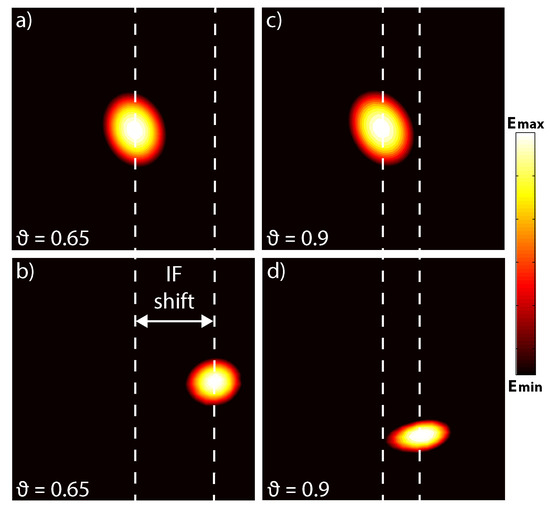
Figure 6.
Simulated field distributions of the (a,c) incident and (b,d) reflected beam center at the angle of incidence (a,b) and (c,d) radians. Here, we consider the beam and material parameters presented in Figure 2b and working region nm within the uniaxial slab interface at the incident wavelength nm. The IF shift represents the lateral distance between the incident and reflected beam centers, and is 160 nm for and 65 nm for radians, respectively. Pronounced Goos-Hänchen shift of 150 nm occurs for (d).
4. Conclusions
In summary, we have investigated the influence of medium anisotropy on the IF shifts and the PSHE of the polarized optical beams within the paraxial approximation in reflection and transmission. We have shown that the polarization mixing caused by anisotropy brings novel essential contribution with unconventional polarization dependence. The polarization-mixing term can be comparable or even more prominent than standard pure polarization term discovering new possibilities for the transverse optical beam shifts.
It is important to note that the considered cases are typical for most of natural uniaxial crystals and commercial wave plates while their thickness is hundreds of times bigger. Thus, the polarization-mixing contribution effect must be taken into account for major part of research devoted to optical beam shifts and spin-orbital interaction phenomena. One should take into account that for generic non-paraxial optical fields, the discussed effect of the polarization mixing can be even more pronounced. Apart from natural anisotropic materials, metamaterials can exhibit large anisotropy and are the key to significantly enhancing the PSHE. Our findings may provide further understanding for the enhancement of PSHE on anisotropic materials and structures, and could be extended for biaxial and hyperbolic media actively attracting attention in quantum physics.
Author Contributions
Conceptualization, M.M., O.Y. and A.V.L.; Software, M.M. and I.D.; Validation, M.M. and I.D.; Formal Analysis, M.M. and O.Y.; Writing—Original Draft Preparation, O.Y.; Writing—Review and Editing, all authors; Visualization, M.M. and O.Y.; Supervision, O.Y., A.B. and A.V.L. All authors have read and agreed to the published version of the manuscript.
Funding
This research was funded by Russian Foundation for Basic Research (grant 20-02-00636). O.Y. and A.B. acknowledge support from the Foundation for the Advancement of Theoretical Physics and Mathematics “BASIS”. O.T. and A.L. acknowledge support from the Independent Research Fund Denmark, DFF Research Project 2 “PhotoHub” (8022-00387B).
Conflicts of Interest
The authors declare no conflict of interest.
Abbreviations
The following abbreviations are used in this manuscript:
| PSHE | Photonic spin Hall effect |
| IF | Imbert-Fedorov |
| PM | Polarization mixing |
| TE | Transverse electric |
| TM | Transverse magnetic |
| QWP | Quarter-wave plate |
Appendix A. Derivation of Fresnel Coefficients for Uniaxial Slab
Any anisotropic slab can be characterized by four reflection ( and ) and four transmission ( and ) coefficients forming the total Fresnel matrix (1). The first and second indices mean the polarization of incident and reflected/transmitted waves, respectively. The reflection and transmission coefficients for the beam plane-wave components were obtained in analytical form following the derivations given in Ref. [35] for an uniaxial plate surrounded by vacuum for simplicity. We assume that z- and x-axis are perpendicular and parallel to the slab interface, respectively, and both axes are directed along the corresponding components of the wave vector of an incident plane wave . We also introduce the angle between x-axis and optical axis lying in the plane of the slab interface.
The Fresnel coefficients for both polarizations can be derived from the boundary conditions for electromagnetic fields at uniaxial slab interface using the following compact matrix equations [35]
Here, and are column vectors expressed through reflection and transmission coefficients as follows
where is the wavevector in free space and is the angle of incidence. The layer matrix depends on the ordinary () and extraordinary () refractive indices and the thickness () of a uniaxial slab. It could be derived in terms of interface mode matrix and phase matrix as follows
The matrix is derived from the boundary conditions, while the matrix accounts for the wave propagation within the slab:
where , and are z-components of ordinary and extraordinary wave vectors in the slab, respectively. Note that -matrix and column vectors ( and ) elements have different dimensionality, but complement each other folding complete boundary conditions. In this notation, becomes a transfer matrix not in the basis of ordinary and extraordinary plane waves, but rather in the basis of their certain linear combination.
Then, we finally find the Fresnel coefficients by solving the system of linear Equations (A1), which is equivalent to eight equations for eight Fresnel coefficients – and . In our case, when optical axis is parallel to slab interface, we obtain explicitly the symmetric relations and resulting in six independent Fresnel coefficients that constitute the total Fresnel matrix (1). Some example plots for reflectances and transmittances of a beam central plane wave are shown as functions of incidence angle in Figure 2a (note that in this case and , hence reflectances are not marked) and Figure 4k–l in the main text for specific and .
The Fresnel tensor relating the incident and secondary fields in the beam coordinate frame has the form
where is the Fresnel matrix for the uniaxial crystal slab (1), and is the rotation matrix from beam coordinate frame to the basis of s and p modes represented in paraxial approximation [32] as
where is the transverse deflection of a non-central wave vector of a certain plane wave from the plane of incidence corresponding to the central plane wave of a beam. The explicit form of a Fresnel tensor (2) is derived by following Euations (A5) and (A6) and neglecting terms.
Appendix B. Numerical Simulation
The numerical simulations were conducted using the finite element method (COMSOL Multiphysics). We used a paraxial Gaussian beam with beam parameter corresponding the the beam waist equal to the incident wavelength. Then, we simulated oblique incidence of a Gaussian beam on the uniaxial slab in a 3D model surrounded by perfectly matched layer box at the typical optical wavelength nm. The material parameters and beam polarization correspond to ones considered in Section 3. First, we have calculated the case without slab to obtain the incident field. Then, we have simulated the beam incidence on the slab giving the total field consisting of incident and reflected fields. The reflected field was obtained by subtracting the incident field calculated without slab at the first step from the total field calculated with slab.
References
- Landau, L.D.; Lifshitz, E.M. Mechanics. In Course of Theoretical Physics; Institute of Physical Problems, USSR Academy of Sciences: Moscow, Russia, 1976; Volume 1. [Google Scholar]
- Maxwell, J.C. A Treatise on Electricity and Magnetism; Clarendon Press: Oxford, UK, 1873; Volume 1. [Google Scholar]
- Lebedev, P. Experimental examination of light pressure. Ann. Phys. 1901, 6, 433. [Google Scholar]
- Nichols, E.F.; Hull, G.F. A preliminary communication on the pressure of heat and light radiation. Phys. Rev. (Ser. I) 1901, 13, 307. [Google Scholar] [CrossRef]
- Poynting, J.H. The wave motion of a revolving shaft, and a suggestion as to the angular momentum in a beam of circularly polarised light. Proc. R. Soc. Lond. A 1909, 82, 560–567. [Google Scholar]
- Allen, L.; Beijersbergen, M.W.; Spreeuw, R.; Woerdman, J. Orbital angular momentum of light and the transformation of Laguerre-Gaussian laser modes. Phys. Rev. A 1992, 45, 8185. [Google Scholar] [CrossRef]
- Bliokh, K.Y.; Rodríguez-Fortuño, F.J.; Nori, F.; Zayats, A.V. Spin—Orbit interactions of light. Nat. Photonics 2015, 9, 796–808. [Google Scholar] [CrossRef]
- Cardano, F.; Marrucci, L. Spin—Orbit photonics. Nat. Photonics 2015, 9, 776–778. [Google Scholar] [CrossRef]
- Bliokh, K.Y.; Bekshaev, A.Y.; Nori, F. Extraordinary momentum and spin in evanescent waves. Nat. Commun. 2014, 5, 1–8. [Google Scholar] [CrossRef]
- Aiello, A.; Banzer, P.; Neugebauer, M.; Leuchs, G. From transverse angular momentum to photonic wheels. Nat. Photonics 2015, 9, 789–795. [Google Scholar] [CrossRef]
- Yermakov, O.Y.; Ovcharenko, A.I.; Bogdanov, A.A.; Iorsh, I.V.; Bliokh, K.Y.; Kivshar, Y.S. Spin control of light with hyperbolic metasurfaces. Phys. Rev. B 2016, 94, 075446. [Google Scholar] [CrossRef]
- Fedorov, F. K teorii polnogo otrazheniya. Dokl. Akad. Nauk SSSR 1955, 105, 465–468. [Google Scholar]
- Imbert, C. Calculation and experimental proof of the transverse shift induced by total internal reflection of a circularly polarized light beam. Phys. Rev. D 1972, 5, 787. [Google Scholar] [CrossRef]
- Bliokh, K.Y.; Bliokh, Y.P. Conservation of angular momentum, transverse shift, and spin Hall effect in reflection and refraction of an electromagnetic wave packet. Phys. Rev. Lett. 2006, 96, 073903. [Google Scholar] [CrossRef] [PubMed]
- Hosten, O.; Kwiat, P. Observation of the spin Hall effect of light via weak measurements. Science 2008, 319, 787–790. [Google Scholar] [CrossRef] [PubMed]
- Liu, Y.; Ke, Y.; Luo, H.; Wen, S. Photonic spin Hall effect in metasurfaces: A brief review. Nanophotonics 2017, 6, 51–70. [Google Scholar] [CrossRef]
- Ling, X.; Zhou, X.; Huang, K.; Liu, Y.; Qiu, C.W.; Luo, H.; Wen, S. Recent advances in the spin Hall effect of light. Rep. Prog. Phys. 2017, 80, 066401. [Google Scholar] [CrossRef] [PubMed]
- Zhou, X.; Li, X.; Luo, H.; Wen, S. Optimal preselection and postselection in weak measurements for observing photonic spin Hall effect. Appl. Phys. Lett. 2014, 104, 051130. [Google Scholar] [CrossRef]
- Zhou, X.; Sheng, L.; Ling, X. Photonic spin Hall effect enabled refractive index sensor using weak measurements. Sci. Rep. 2018, 8, 1–8. [Google Scholar] [CrossRef]
- Qin, Y.; Li, Y.; Feng, X.; Liu, Z.; He, H.; Xiao, Y.F.; Gong, Q. Spin Hall effect of reflected light at the air-uniaxial crystal interface. Opt. Express 2010, 18, 16832–16839. [Google Scholar] [CrossRef]
- Bliokh, K.Y.; Samlan, C.; Prajapati, C.; Puentes, G.; Viswanathan, N.K.; Nori, F. Spin-Hall effect and circular birefringence of a uniaxial crystal plate. Optica 2016, 3, 1039–1047. [Google Scholar] [CrossRef]
- Bliokh, K.; Prajapati, C.; Samlan, C.; Viswanathan, N.K.; Nori, F. Spin-Hall effect of light at a tilted polarizer. Opt. Lett. 2019, 44, 4781–4784. [Google Scholar] [CrossRef]
- Takayama, O.; Puentes, G. Enhanced spin Hall effect of light by transmission in a polymer. Opt. Lett. 2018, 43, 1343–1346. [Google Scholar] [CrossRef] [PubMed]
- Lekenta, K.; Król, M.; Mirek, R.; Łempicka, K.; Stephan, D.; Mazur, R.; Morawiak, P.; Kula, P.; Piecek, W.; Lagoudakis, P.G. Tunable optical spin Hall effect in a liquid crystal microcavity. Light. Sci. Appl. 2018, 7, 1–6. [Google Scholar] [CrossRef] [PubMed]
- Yin, X.; Ye, Z.; Rho, J.; Wang, Y.; Zhang, X. Photonic spin Hall effect at metasurfaces. Science 2013, 339, 1405–1407. [Google Scholar] [CrossRef]
- Luo, W.; Xiao, S.; He, Q.; Sun, S.; Zhou, L. Photonic spin Hall effect with nearly 100% efficiency. Adv. Opt. Mater. 2015, 3, 1102–1108. [Google Scholar] [CrossRef]
- Shaltout, A.; Liu, J.; Kildishev, A.; Shalaev, V. Photonic spin Hall effect in gap–plasmon metasurfaces for on-chip chiroptical spectroscopy. Optica 2015, 2, 860–863. [Google Scholar] [CrossRef]
- Puentes, G. Spin-Orbit Angular Momentum Conversion in Metamaterials and Metasurfaces. Quantum Rep. 2019, 1, 10. [Google Scholar] [CrossRef]
- Kapitanova, P.V.; Ginzburg, P.; Rodríguez-Fortuño, F.J.; Filonov, D.S.; Voroshilov, P.M.; Belov, P.A.; Poddubny, A.N.; Kivshar, Y.S.; Wurtz, G.A.; Zayats, A.V. Photonic spin Hall effect in hyperbolic metamaterials for polarization-controlled routing of subwavelength modes. Nat. Commu. 2014, 5, 1–8. [Google Scholar] [CrossRef] [PubMed]
- Takayama, O.; Sukham, J.; Malureanu, R.; Lavrinenko, A.V.; Puentes, G. Photonic spin Hall effect in hyperbolic metamaterials at visible wavelengths. Opt. Lett. 2018, 43, 4602–4605. [Google Scholar] [CrossRef] [PubMed]
- Kim, M.; Lee, D.; Kim, T.H.; Yang, Y.; Park, H.J.; Rho, J. Observation of enhanced optical spin Hall effect in a vertical hyperbolic metamaterial. ACS Photonics 2019, 6, 2530–2536. [Google Scholar] [CrossRef]
- Bliokh, K.Y.; Aiello, A. Goos–Hänchen and Imbert–Fedorov beam shifts: An overview. J. Opt. 2013, 15, 014001. [Google Scholar] [CrossRef]
- Born, M.; Wolf, E. Principles of Optics: Electromagnetic Theory of Propagation, Interference and Diffraction of Light; Elsevier: Amsterdam, The Netherlands, 2013. [Google Scholar]
- Dennis, M.R.; Götte, J.B. The analogy between optical beam shifts and quantum weak measurements. New J. Phys. 2012, 14, 073013. [Google Scholar] [CrossRef]
- Lekner, J. Optical properties of a uniaxial layer. Pure Appl. Opt. 1994, 3, 821–837. [Google Scholar] [CrossRef][Green Version]
© 2020 by the authors. Licensee MDPI, Basel, Switzerland. This article is an open access article distributed under the terms and conditions of the Creative Commons Attribution (CC BY) license (http://creativecommons.org/licenses/by/4.0/).