Article

Conceptual Design and Regulatory Framework of a Modular Electric Propulsion System for Urban and Industrial Vehicles


by
David Abellán-López
,
Francisco J. Simón-Portillo
,
Abel R. Navarro-Arcas
* and
Miguel Sánchez-Lozano
Institute for Engineering Research (I3E), Miguel Hernández University of Elche, 03202 Alicante, Spain
*
Author to whom correspondence should be addressed.
Vehicles 2026, 8(4), 91; https://doi.org/10.3390/vehicles8040091
Submission received: 30 January 2026 / Revised: 8 April 2026 / Accepted: 10 April 2026 / Published: 13 April 2026

Abstract

The electrification of urban and industrial transport is driving the need for propulsion architectures that combine energy efficiency, operational flexibility and regulatory compliance. However, current electric platforms often lack the adaptability required for customized body configurations and multistage manufacturing, and their approval is hindered by the complexity of meeting electrical safety and electromagnetic compatibility (EMC) requirements at vehicle level. This article presents the conceptual design of a modular electric propulsion module developed within the MODULe project, in which the traction motor, inverter, battery pack, Battery Management System (BMS) and cooling circuits are integrated into a standardized module conceived as an Independent Technical Unit (ITU). The propulsion module dimensioned using a modified WLTP cycle, and the results indicate that the selected components can meet the dynamic demands of light and medium-duty vehicles, achieving an estimated consumption of around 50 kWh/100 km and a driving range above 160 km. By concentrating the critical regulatory requirements within a single module, the proposed architecture facilitates multistage vehicle approval, reduces development effort and supports the scalable electrification of commercial fleets. This approach may contribute to accelerating the deployment of zero-emission vehicles in urban logistics and industrial applications, with potential benefits for both the sector and society.

1. Introduction

The electrification of urban and industrial transportation has become a key strategy in the transition toward sustainable, efficient, and zero-emission mobility. This trend is reinforced by increasingly restrictive emission regulations in European cities, the expansion of low-emission zones, and the need to decarbonize last-mile logistics and municipal services. Sectors such as waste collection, parcel delivery, refrigerated transport or urban construction are experiencing a rapid shift toward electric solutions due to operational constraints, noise-reduction requirements and rising fuel costs. This process, driven by environmental policies, technological advances, and the growing demand for clean energy solutions, has fostered an innovation ecosystem around the design of electric vehicles (EVs) adaptable to multiple operational environments [1,2].
However, the diversity of vehicle typologies, duty cycles, and regulatory requirements poses significant challenges in terms of standardization, scalability, and technical compatibility. Existing electric platforms often rely on bespoke integrations of batteries, inverters and auxiliary systems, which complicates their reuse across different vehicle categories and increases development time. Moreover, the approval of each configuration typically requires repeating electrical safety and EMC tests at vehicle level, making small-series production economically unfeasible. In particular, vehicles intended for public services, urban logistics, or industrial applications require flexible solutions capable of adapting to specific configurations without compromising safety or energy efficiency [3].
In this context, modular architectures have emerged as a promising solution. They enable the flexible integration of propulsion systems, energy storage, and thermal management into ITUs, facilitating their approval and reuse across different vehicle platforms [4,5]. Modularity not only improves multistage efficiency but also allows functional and spatial customization tailored to the specific needs of each application.
Several initiatives in the automotive and industrial-vehicle sectors have explored modular approaches, including scalable skateboard platforms, interchangeable battery systems and reconfigurable powertrain modules for light commercial vehicles. These efforts highlight the potential of modularity to reduce integration complexity and accelerate electrification, but they often remain limited to specific vehicle families or lack a regulatory-oriented design that enables their approval as ITUs. This gap reinforces the need for modular propulsion systems conceived from the outset to support multistage manufacturing and compliance with UNECE regulations.
Despite these advances, there is still a lack of propulsion modules that combine modularity, regulatory compliance and adaptability to the wide variety of body configurations used in urban and industrial fleets. Manufacturers and bodybuilders often face long integration cycles, duplicated testing procedures and limited flexibility when electrifying vehicles in small series. Addressing these limitations requires propulsion modules that can be certified independently as ITUs, integrated into different chassis layouts and connected to the rest of the vehicle through low-voltage (LV) interfaces that do not compromise EMC. A detailed description of the proposed modular propulsion architecture is provided in Section 3.
Beyond the practical development of the prototype, this work aims to contribute to the scientific debate on electrification strategies for urban and industrial vehicles. It complements previous conceptual developments and provides a technical framework that can serve as a basis for future research on scalable electric platforms and the integration of modular propulsion systems. The main contribution of the work described here is the definition of a compact propulsion module, integrating an electrical and control architecture designed to comply with UNECE regulatory requirements, which can facilitate and make viable the multistage manufacturing of customized vehicles, or the retrofitting and electrification of vehicles already in circulation. Furthermore, another significant contribution is the detailed performance evaluation based on a modified WLTP cycle, which can serve as a reference for assessing the real-world feasibility of using this type of vehicle.
The remainder of the article is structured as follows: Section 2 presents a review of the state of the art in modular architectures, electric powertrain integration, and applicable regulatory frameworks. Section 3 describes the conceptual design of the MODULe propulsion system. Section 4 details the methodology, including the sizing criteria and the definition of the modified WLTP cycle used to assess its performance. Section 5 reports the dynamic and energy results obtained, with particular attention to power flow, energy recovery, and the estimated driving range. Section 6 discusses the technical and regulatory implications of the proposed approach, while Section 7 summarizes the main conclusions and outlines future lines of work. Finally, Section 8 lists the industrial-property registrations associated with the developments presented in this work.

2. Literature Review

2.1. Modular Architectures for Electric Vehicles

Modularity in electric vehicle design has been widely recognized as an effective strategy to address the diversity of applications, facilitate scalability, and reduce development costs. Several studies have explored how modular architectures enable the flexible integration of electrical subsystems, from the traction system to energy storage and control systems [5,6].
In particular, Kraus et al. [7] propose a cloud-enabled reconfigurable electrical/electronic architecture that allows the vehicle configuration to be dynamically adapted according to operational needs. This reconfiguration capability is especially relevant in urban environments, where vehicles must respond to changing conditions of load, traffic, and range.
The concept of modularity has also been applied to scalable test platforms, such as the one developed by Kardasz and Kazerani [6], which enables the evaluation of traction system configurations in controlled environments. These platforms facilitate component validation and the simulation of real-world operating scenarios, contributing to the development of homologable solutions.
Furthermore, Ferreira et al. [8] introduce a modular architecture for drones, highlighting the applicability of the modular approach beyond the terrestrial domain. Although focused on UAVs, the study provides design principles that can be extrapolated to industrial vehicles, particularly regarding functional compartmentalization and distributed thermal management.
These approaches align with the philosophy of the MODULe system, which adopts a modular architecture oriented toward the integration of electrical subsystems into an ITU, facilitating its approval and reuse across different vehicle platforms.
Beyond these contributions, several authors have analyzed the impact of modularity on design flexibility and the scalability of electric platforms. Schneider et al. [9] propose a modular system for electrified powertrains that allows flexible configuration of the battery, inverter, electric machine, and transmission according to the vehicle segment and life-cycle sustainability requirements. Similarly, Schindewolf et al. [10] examine modular electrical and electronic architectures for next-generation vehicles, emphasizing the role of interface standardization in reducing integration complexity. These approaches reinforce the relevance of conceiving the propulsion module as a reconfigurable technical unit aligned with diversified vehicle platforms and flexible production strategies.
Despite the variety of modular approaches described in the literature, it is important to note that most of them are oriented toward passenger cars or light commercial vehicles and focus primarily on the spatial distribution of components rather than on the definition of a fully integrated propulsion module. To the best of the authors’ knowledge, no previous work has reported a modular architecture for industrial electric vehicles that integrates the traction motor, inverter, battery pack, BMS, cooling system, and safety elements into a single unit conceived for UNECE approval as an ITU or for incorporation into multistage manufacturing processes.
This absence is particularly relevant in the context of urban and industrial vehicles, where bodybuilders and second-stage manufacturers require propulsion solutions that can be incorporated into different chassis configurations without repeating full-vehicle electrical safety and EMC testing. Existing modular concepts, such as skateboard platforms, interchangeable battery systems, or reconfigurable e-axles, provide valuable principles, but none of them constitutes a complete propulsion module suitable for industrial applications.
During the preliminary design phase of the MODULe system, the authors also evaluated alternative architectures, including configurations with two independent motors driving each wheel of the traction module. This solution offered certain advantages in terms of mechanical simplicity, by eliminating transmission elements and enabling more direct torque distribution, but it involved significantly greater technical complexity. In particular, it posed additional challenges related to thermal management, EMC, torque synchronization between wheels, and functional safety requirements. Moreover, its integration was less suitable for retrofit applications, which represent a relevant use case in industrial fleets. For these reasons, the dual-motor configuration was ultimately discarded in favor of a more robust, integrable architecture compatible with multistage manufacturing processes.
These considerations highlight the need for a modular propulsion architecture specifically conceived for industrial vehicles, capable of combining functional integration, regulatory compliance, and adaptability to a wide variety of body configurations.

2.2. Integration of Powertrain and Power Electronics

The integration of electric propulsion systems in industrial and urban vehicles requires precise coordination between the motor, inverter, BMS, on-board charger (OBC), and DC/DC converters. This integration must not only ensure energy efficiency and operational reliability but also comply with electrical safety, EMC, and thermal management requirements.
Several studies have addressed the integration of electric motors and transmissions in light platforms, highlighting the importance of component compatibility and the optimization of available space. Robinette [11] presents a comparative analysis of traction system configurations for light electric vehicles, emphasizing the need for compact and scalable solutions that can adapt to different vehicle architectures.
In the field of power electronics, Savio et al. [12] propose a dual-mode bridgeless interleaved converter for electric vehicle battery chargers, which improves efficiency and reduces switching losses. This type of solution is particularly relevant in modular systems, where energy density and thermal dissipation are critical factors. Along the same lines, recent industrial studies highlight the advantages of integrating the charger, inverter, and DC/DC converters into a single power module to reduce costs and improve vehicle range [13].
Thermal management also plays a key role in the integration of propulsion systems. Pan and Li [14] apply model-based predictive control using Koopman operators to optimize the operation of integrated thermal systems, demonstrating significant improvements in thermal stability and energy efficiency. Complementarily, Moreno et al. [15] analyze current challenges in the thermal management of power electronics, proposing strategies to improve reliability and extend component lifetime.
The functional integration of the powertrain and power electronics has been identified as a key vector for reducing costs, improving power density, and increasing the range of electric vehicles. Recent studies on modular electrified propulsion systems highlight the benefits of integrating the OBC, DC/DC converters, and inverters into compact units that share power stages and cooling systems, minimizing the number of components and the total system weight. Schneider et al. [13] show how these approaches enable the configuration of families of electrified powertrains based on standardized modular blocks, with different combinations of power, torque, and energy storage capacity.
In this context, the proposed MODULe propulsion system can be understood as a specific realization of these integration trends. A detailed description of its architecture and implementation is provided in Section 3.

2.3. Regulatory Framework and Certification Strategies

The approval and deployment of electric vehicles require strict adherence to regulatory frameworks that govern electrical safety, EMC, energy efficiency and communication protocols. Within the European Union, Regulation (EU) 2018/858 [16] establishes the general principles for the approval of vehicles and technical systems, defining requirements related to safety, environmental performance and interoperability. For electric powertrains, several UNECE regulations and international standards play a central role, each of them directly linked to specific subsystems of the propulsion architecture.
A key reference is UNECE R100 [17], which defines the electrical safety requirements applicable to high-voltage (HV) components such as the traction motor, inverter, battery pack, BMS and charging interfaces [18]. Part I focuses on protection against direct and indirect contact, insulation resistance and dielectric strength, while Part II specifies the mechanical integrity, enclosure protection and thermal safety requirements for rechargeable energy storage systems [19]. These provisions directly influence the design of battery housings, the routing and shielding of HV cables and the integration of protective devices.
EMC is regulated by UNECE R10, which applies to all components capable of emitting or being affected by electromagnetic disturbances. Inverters, DC/DC converters, OBCs and HV wiring must comply with limits on radiated and conducted emissions, while also demonstrating immunity to external electromagnetic fields. This regulation affects switching strategies, cable harness design and the implementation of shielding and grounding schemes.
Energy consumption and range are evaluated under the Worldwide Harmonized Light Vehicles Test Procedure (WLTP), defined in UNECE R154 [20,21,22]. Although originally conceived for light commercial vehicles, its adaptation to N2-category industrial platforms is essential to ensure that homologation results reflect realistic operating conditions. The procedure determines the test cycle, ambient conditions and measurement methodology, and therefore has a direct impact on battery sizing, control system calibration and performance assessment.
In addition to UNECE regulations, several international standards complement the approval process. IEC 61851-1 [23] defines the safety requirements for conductive charging systems, including communication between the vehicle and the charging station. ISO 26262 [20] establishes the functional safety framework for road vehicles, affecting the design of control units, torque management algorithms and diagnostic strategies. Communication protocols such as CAN (ISO 11898) [24] ensure interoperability between devices from different manufacturers and are essential for the integration of distributed control architectures.
While electric propulsion offers new opportunities for flexible layouts and customized vehicle configurations, these possibilities are constrained by the cost and complexity of regulatory testing. Electrical safety and EMC assessments are particularly demanding, and performing full certification for each customized configuration is economically unfeasible for most bodybuilders.
Regulation (EU) 2018/858 addresses this challenge by allowing the approval of ITUs and enabling multistage vehicle approval. This framework makes it possible to certify a standardized traction unit in a first stage, followed by its integration into customized vehicle designs in a second stage, where only the additional systems require further testing. This approach significantly reduces certification costs and facilitates the deployment of electric powertrains in industrial applications.
Beyond the European context, other regions apply comparable but distinct regulatory approaches. In the United States, electrical safety is governed by FMVSS 305 [25], while EMC falls under FCC regulations and charging systems follow SAE standards such as SAE J1772 [26]. China applies the GB/T 18384 series for electric-vehicle safety [27], GB/T 18487 [28] for conductive charging and GB/T 31467 [29] for battery performance and safety. Japan, through METI and JASIC, enforces regulations closely aligned with UNECE rules, reflecting its participation in the 1958 Agreement. Although these frameworks share common objectives, they differ in testing procedures, subsystem-level requirements and certification pathways, which must be considered when designing electric powertrains intended for global markets.

2.4. Applications and Thermal-Energy Management in Modular Electric Vehicles

The implementation of modular electric propulsion systems in urban and industrial environments presents specific challenges related to energy demand, thermal stability, and operational flexibility. Modular architectures offer a scalable solution that can be adapted to a wide range of vehicle configurations—from light delivery vans to medium-duty municipal trucks—without the need to redesign the entire system [5,30].
In the field of urban logistics, Aiello et al. [31] demonstrated the benefits of modular battery systems in electrically assisted cargo bicycles, highlighting how energy flexibility improves operational efficiency in dense environments. Ferreira and Esperança [3] expanded this perspective by incorporating artificial intelligence algorithms for route optimization and fleet management, reinforcing the role of modularity in the adaptability of propulsion systems.
Thermal management is a critical aspect for system reliability and energy efficiency. Pan and Li [14] applied predictive control based on Koopman models to integrated thermal systems, achieving significant improvements in temperature stability and energy utilization. Moreno et al. [15] identified the main challenges in cooling power electronics, proposing adaptive systems that respond dynamically to load and temperature conditions.
Energy efficiency is further enhanced through regenerative braking strategies, torque modulation, and dynamic parameter configuration using tools such as AEMcal. The use of bridgeless interleaved converters, such as the one proposed by Savio et al. [12], helps reduce switching losses and improve charging performance, aligning with the objectives of modular systems in terms of scalability, safety, and operational optimization.

3. Conceptual Description of the MODULe Propulsion System

The MODULe project, led by Miguel Hernández University of Elche and funded by the Valencian Innovation Agency, is framed within this vision. Its objective is to develop a modular and scalable electric propulsion module suitable for integration into urban and industrial vehicles through multistage manufacturing processes. The proposed design materializes in a compact module that integrates an electric motor, inverter, batteries, control unit, cooling system and safety elements, conceived for installation in different chassis and body configurations.
The design of the propulsion module is fully aligned with the regulatory requirements discussed in Section 2.3, which define the electrical-safety, EMC and functional-safety constraints that guided the architecture of the system.
The development of the MODULe system builds on the research team’s previous work, which includes conceptual proposals and industrial-property-protected results. Among these precedents is an initial utility model focused on the design of a modular electric vehicle for goods transport and delivery, which established the foundations of a flexible and reconfigurable platform [32]. This was followed by an architectural proposal for light electric commercial vehicles, in which structural configurations and integration criteria for traction systems in urban environments were analyzed [33]. More recently, a second utility model was registered, centered on a modular electric propulsion device attachable to a truck chassis, conceived for certification as an ITU and for incorporation into multistage manufacturing processes [34]. Together, these developments provide the conceptual and technological foundation on which the MODULe system is built, reinforcing its orientation toward modularity, scalability and regulatory compliance.
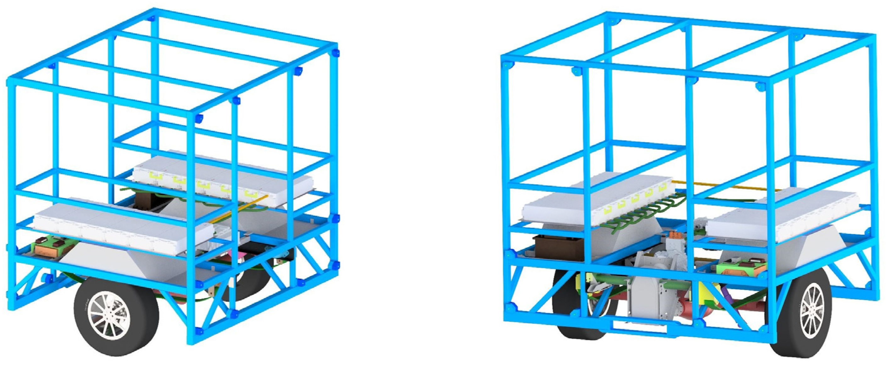
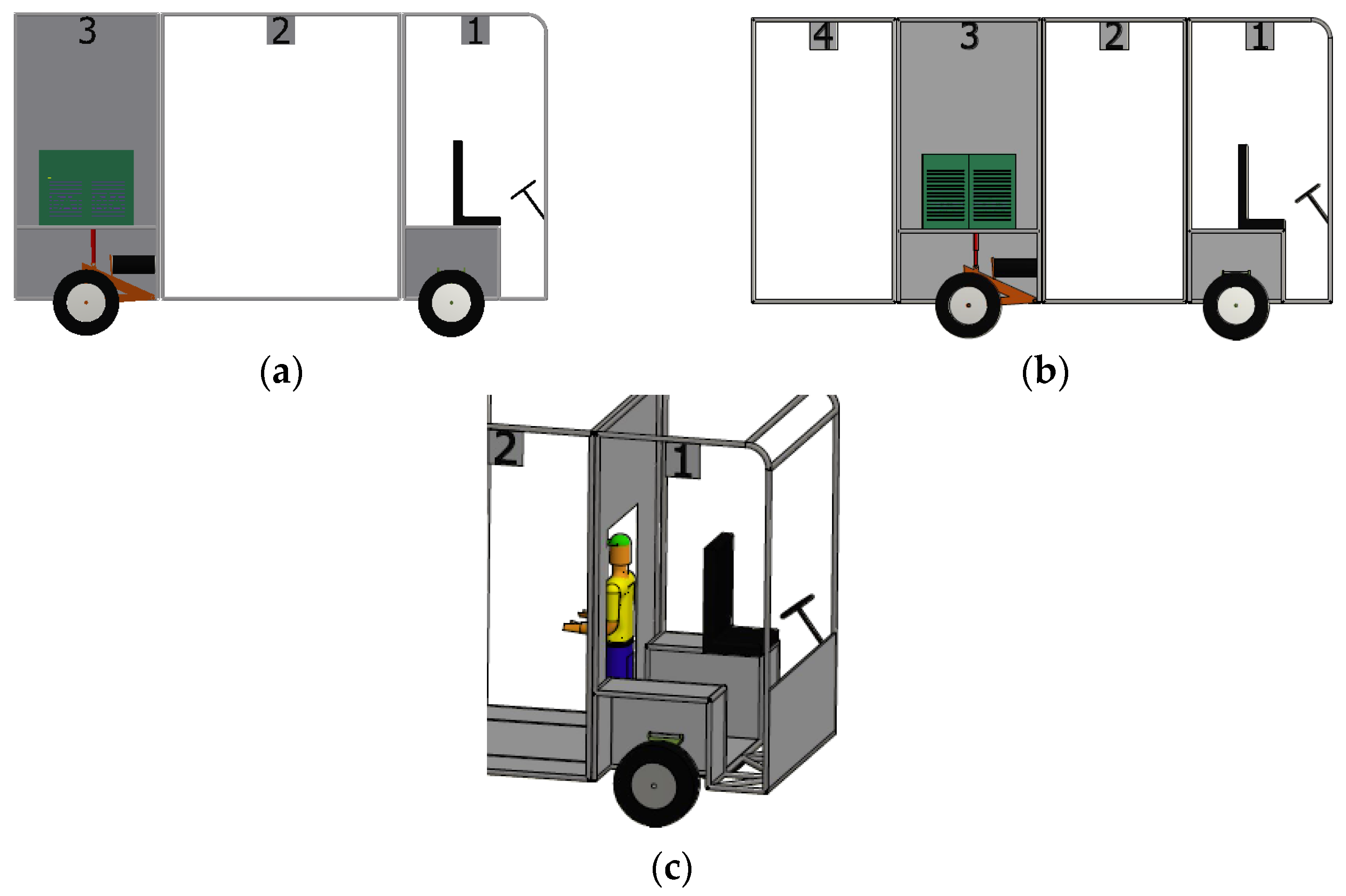
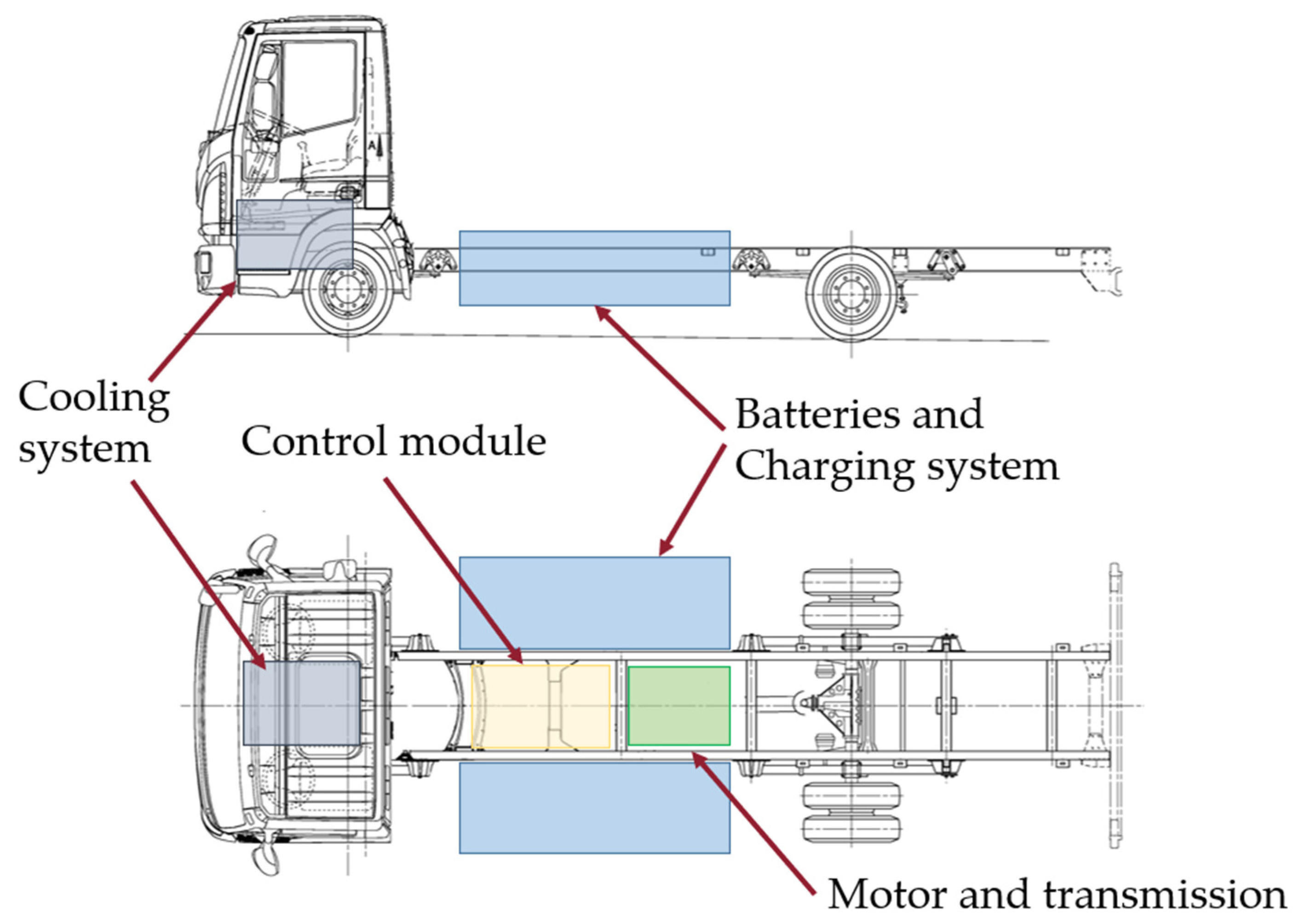
Figure 1, extracted from the aforementioned utility model [33], illustrates how the propulsion module is conceived as an ITU that can be integrated into different vehicle platforms.
Although the previously registered utility models established the conceptual basis for a modular vehicle architecture, the present work advances beyond those developments by detailing the design and integration of a complete electric propulsion module intended for multistage manufacturing and regulatory approval. The MODULe system consolidates the traction motor, inverter, battery pack, BMS, cooling circuits and safety elements into a unified technical unit designed to meet the electrical-safety and EMC requirements of UNECE regulations. In addition, the article describes the electrical and control architecture implemented in the prototype, together with the sizing criteria and performance assessment based on a modified WLTP cycle. This contribution therefore provides a comprehensive technical definition of the propulsion module and examines its feasibility within realistic operational and regulatory constraints.
The concentration of all HV subsystems—traction motor, inverter, battery pack, BMS, OBC and their associated cooling circuits—within a single module enables comprehensive validation of electrical-safety and electromagnetic-shielding requirements. By consolidating these elements into a standardized technical unit, regulatory compliance can be verified on a single platform rather than on each individual vehicle configuration. This approach allows the module to be approved in a first stage as an “incomplete” traction system, which cannot yet be authorized for road use. In a subsequent stage, another manufacturer may integrate this standardized unit into a customized vehicle design, adding the remaining systems required for cargo handling, circulation and operational use. In the resulting “completed vehicle”, it is no longer necessary to repeat the tests already performed on the standardized traction module, which significantly reduces certification costs and facilitates market deployment.
The modular architecture also supports efficient management of communication networks and analog signals, simplifying the integration of control and diagnostic systems. The use of programmable Controller Area Network (CAN) gateways enables the incorporation of devices from different manufacturers without compromising system integrity, while ensuring compliance with interoperability requirements established by European regulations. Overall, modularity becomes a strategic advantage for homologation, reducing certification time and cost while enhancing scalability and adaptability across a wide range of industrial electric-vehicle applications. This approach also concentrates the critical requirements of electrical safety, EMC and thermal management within a standardized unit, simplifying regulatory validation and supporting the optimization of available space, energy efficiency and performance across different driving cycles [7,35].
The traction module is designed as an independent unit that concentrates all propulsion subsystems, while also allowing a cargo module to be mounted on top of it when required. To the best of our knowledge, the literature does not report fully integrated traction modules conceived as self-contained propulsion units and suitable for certification as ITUs. Several modular vehicle architectures have been described in patent documents, which outline conceptual or pre-industrial designs combining cab, drive and load structures in different configurations. However, these approaches implement modularity at the vehicle level and do not define a standalone traction module that encapsulates propulsion, energy storage and auxiliary systems within a single unit. This distinction frames the novelty of the proposed architecture and explains the absence of directly comparable solutions in publicly available sources.
To further contextualize the proposed architecture within existing modular vehicle concepts, Table 1 summarizes the main differences between representative modular approaches described in the patent literature and the traction-module architecture developed in this work. While these prior solutions share the idea of distributing propulsion components near the driven axle and separating the vehicle into cab, drive and load structures, they implement modularity at the vehicle level. None of them defines a dedicated traction module that encapsulates propulsion, energy storage and auxiliary systems as a standalone unit.
These comparisons highlight that existing modular vehicle architectures distribute motors, batteries, and structural elements across different modules, but none isolates all propulsion and energy-storage functions within a single, self-contained traction unit. The proposed architecture therefore differs not only in the degree of modularity but also in the granularity at which modularity is applied, concentrating the entire propulsion subsystem in a dedicated module that can be combined with different cab and cargo configurations.
The MODULe system incorporates these strategies through a dual-circuit thermal design and a centralized energy-management architecture that coordinates the operation of the traction motor, inverter, battery pack and auxiliary systems. This configuration ensures thermal stability under varying load conditions and improves overall energy efficiency in urban and industrial applications, where frequent stop-and-go cycles and variable duty profiles impose demanding thermal and power requirements.
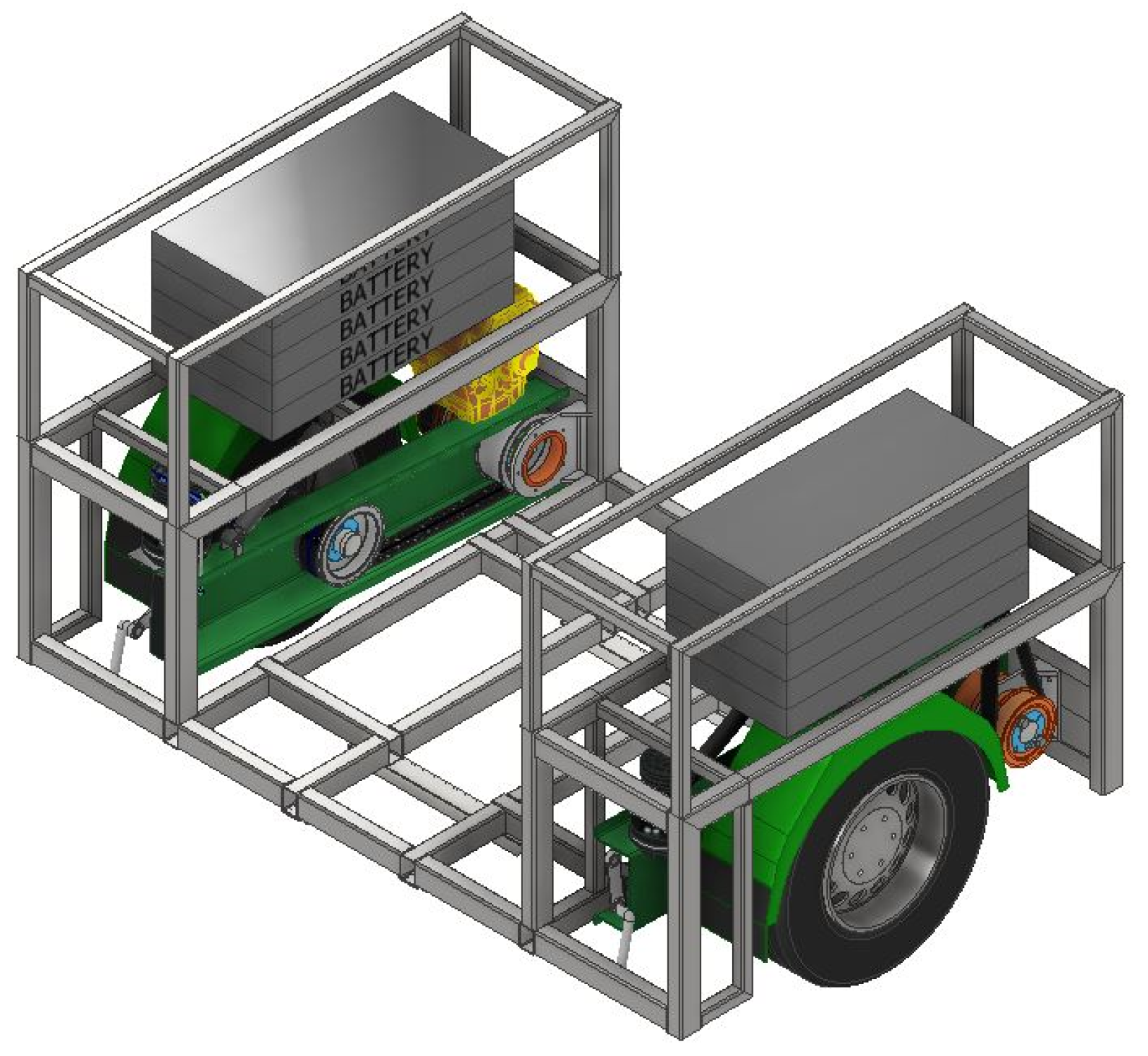
During the preliminary design phase, several architectural alternatives were evaluated. One of them was a dual-motor configuration, with a separate motor driving each wheel on either side of the drive module. Although this approach offered mechanical simplicity at first glance, by eliminating transmission components, it also introduced greater control complexity. Furthermore, the simplest option of in-wheel motors significantly increases unsprung mass, which can worsen dynamic performance when the vehicle is running with a light load. As an alternative, architectures were proposed featuring independent motors anchored to the structure, and a belt drive system inside the suspension arm, which were difficult to integrate into a compact design. Figure 2 shows a CAD rendering of this configuration.
Due to the aforementioned issues, the dual-motor option was not chosen for the design of the first prototypes, and the design work focused on an architecture that was more easily integrated with a single central motor, in line with the objectives of modularity, ease of manufacturing, and regulatory compliance. However, the architecture with independent drive to each wheel can still be considered valid, and may be of interest in applications where a continuous flat floor between the rear wheels is desired.

4. Materials and Methods

The development of the MODULe propulsion system was approached through a comprehensive methodology that combines functional pre-design, the selection and integration of electrical and mechanical components, and dynamic validation using a representative driving cycle. This approach ensures that the traction module simultaneously meets the operational, energy, and regulatory requirements associated with urban and industrial vehicles. The procedure was applied to the design of a vehicle with a modular architecture and a technically permissible maximum laden mass (TPMLM) of up to 4500 kg.
The methodology is structured into four complementary phases. First, performance, energy consumption, and range requirements are established based on the geometric, aerodynamic, and rolling-resistance characteristics of the base vehicle. Next, the components of the traction system—motor, gear reduction, final drive, batteries, and power electronics—are selected according to their ability to meet these requirements and their compatibility with European approval criteria, and the architecture of the electrical and control system is designed in detail. The integration of the electrical components with the support structure and mechanical systems of the traction module is then addressed, defining the location of each component and the necessary substructures and mounting points. EMC is ensured through the use of shielded wiring, specific fuses such as the Eaton Bussmann EV40-500-C (Eaton–Bussmann Electrical Division, Ellisville, MO, USA), and contactors with feedback signals that allow real-time verification of circuit status.
Finally, the dynamic behavior of the system is validated through the simulation of a modified WLTP cycle, which enables the evaluation of realistic energy demand and the estimation of the vehicle’s operational range.

4.1. General Approach and Design Criteria

The design process of the MODULe system begins with the definition of the minimum functional requirements that the vehicle must meet under real operating conditions. These requirements include the ability to maintain a sustained speed of over 90 km/h on level ground at full load, and the ability to overtake under those conditions. It was also stipulated that the vehicle must be able to climb 16% gradients at speeds above 20 km/h, achieve a minimum operating range of 150–160 km, and comply with the multistage vehicle approval procedures established by Regulation (EU) 2018/858.
To assess the feasibility of these requirements, the physical parameters of the base vehicle were defined, forming the inputs to the dynamic model used in the pre-design stage. Based on the mass, main dimensions, aerodynamic coefficients, and tyre characteristics, the rolling-resistance, grade, and aerodynamic drag forces were calculated, along with the power and torque required at the rear axle for each target operating condition.
Table 2 summarises the general characteristics of the vehicle designed in this study. These are typical values for industrial vehicles with a MTPM of 4500 kg. The procedure would be applicable to vehicles with different characteristics if the appropriate values for these parameters are selected.
The parameters listed in Table 2 describe the geometric, aerodynamic, rolling-resistance and transmission characteristics of the vehicle. MTPM denotes the technically permissible maximum laden mass, while MRO refers to the Mass in Running Order. The tyre parameters include the unloaded tyre radius rn, the slip ratio, the rolling resistance coefficient fr, the loaded radius rc, and the effective rolling radius re, which relates wheel angular speed to vehicle linear speed. The aerodynamic properties comprise the frontal area and the drag coefficient Cx. The transmission parameters include the final drive ratio i0, corresponding to the differential reduction, and the mechanical transmission efficiency nT.
The dynamic model used is based on the balance of longitudinal forces acting on the vehicle loaded to its MTPM. The tractive-resistance force Fr is composed of rolling resistance, the gravitational component associated with the road gradient α, and aerodynamic drag. For the vehicle loaded to MTPM, the corresponding expression is given in Equation (1).
F r = M T P M   g   cos α   f r + M T P M   g sin ( α ) + 1 2   ρ   A     C x     V 2
In this expression, ρ represents the air density and V the vehicle speed. From the tractive-resistance force it is possible to determine the power and torque required to operate under different conditions.
The effective radius, re, was calculated based on the geometric tyre radius, re, and an estimated slip ratio, κ , of 5% (2). This value is used to relate the vehicle’s linear speed to the rotational speed at the wheel axle.
r e = r n   1 κ = 0.325   m
Likewise, the typical transmission ratios of the final-drive units used in N2-category vehicles were considered. Based on the effective tyre radius and the final-drive ratio, the relationship between the vehicle’s forward speed V (m/s) and the rotational speed at the differential input ω m o t o r (rad/s) was established, as shown in Equation (3).
V = r e   2 π   ω m o t o r 60 / i 0
Multispeed gearboxes can optimize vehicle energy consumption. For instance, Hinov et al. [40] demonstrated efficiency gains between 1.7% and 2.4% of efficiency with the introduction of a two-speed transmission, while Yildirim et al. [41] reported improvements of up to 7% across various transmission configurations. However, potential consumption reductions must be weighed against other critical design factors when selecting the number of gear ratios. In this study, a single-speed gearbox was chosen primarily because of the need to design a transmission module that was as compact and versatile as possible, which would facilitate mechanical integration and simplify both control and manufacturing. However, when evaluating the drivetrain as a whole, care was taken to ensure that energy efficiency was not unduly compromised, making sure that the selected motor could operate within an acceptable efficiency range across the entire operating speed range of the vehicle.
On this basis, the sizing criteria for the traction system were defined. Assuming an overall mechanical transmission efficiency of nT = 0.9, the design power and torque values required to meet the specified functional requirements mentioned al the beginning of this section. These values served as technical thresholds for the selection of the motor, the reduction gear, and the differential, as described in Section 4.2. The transmission system was configured to match the engine’s operation to its optimal performance range.

4.2. Selection and Integration of the Traction System

The selection of the traction system was carried out based on the functional requirements established in the pre-design stage and on the need to integrate all electrical subsystems into a compact, scalable module that can be approved as an ITU. The process followed a comparative methodology based on criteria of dynamic performance, energy efficiency, regulatory compatibility, and industrial feasibility.
In a first phase, different combinations of electric motor and reduction gear capable of meeting the minimum values of continuous power, torque at the differential input, and rotational speed defined in Section 4.1 were evaluated. For each alternative, the following aspects were analyzed:
  • the operating voltage range,
  • the torque and power curve,
  • the base speed and maximum speed,
  • the efficiency at the nominal point,
  • the thermal compatibility with the intended cooling system,
  • and the commercial and documentation availability for approval.
Based on this analysis, a set consisting of a permanent-magnet synchronous motor and a fixed-ratio reduction gear was selected, capable of providing the required torque, power, and speed range at the rear axle. Specifically, the powertrain features a Zonic 180 motor (Zonic Motors, Bristol, UK) coupled with a 2.2:1 gear ratio reducer. Both components are provided by the same supplier, ensuring seamless mechanical compatibility and streamlining the design process. Table 3 summarizes the characteristics of the selected motor. The mechanical integration was designed to allow the motor, reduction gear, and differential to be mounted on a single supporting structure, optimizing shaft alignment, thermal dissipation, and maintenance access.
Energy storage was configured using a HV battery pack composed of 12 LG Chem 8S2P Li-ion modules (LG Chem Ltd., Seoul, Republic of Korea) connected in series. Each module has a capacity of 6.85 kWh, a nominal voltage of 29.3 V, a maximum continuous current of 210 A, and a maximum peak current of 420 A. The selection of the pack was based on:
  • the energy capacity required to meet the target range,
  • the voltage range compatible with the inverter,
  • the energy density per unit volume,
  • the cooling capability using liquid plates,
  • and compliance with the electrical safety requirements established by UNECE R100.
The functional integration of the system was structured around a central control unit, the AEM EV VCU (AEM Performance Electronics, Hawthorne, CA, USA), together with an inverter responsible for managing traction, regenerative braking, communication between devices, and the safe sequential activation of HV components. The communication architecture was organized through independent CAN buses for traction, batteries, and diagnostics, ensuring interoperability between devices from different manufacturers.
The thermal design of the module was implemented through a dual-circuit liquid-cooling system: one dedicated to the battery modules and another to the motor and inverter. This separation allows each subsystem to remain within its optimal operating range and facilitates compliance with thermal-safety regulatory requirements.
Regarding thermal safety, the cooling system was designed to comply with the temperature ranges established by lithium-battery regulations, maintaining the cells between 15 °C and 35 °C [42]. This is achieved through dedicated cooling plates and heat-dissipation systems controlled via CAN, such as the TKT HVAC BCS3-CW-24 model (TKT HVAC, Zhengzhou, Henan, China). The MODULe system addresses these requirements through a dual-circuit liquid-cooling architecture—one dedicated to the battery modules and another to the electrical equipment. This separation enables precise thermal control, keeping the batteries within the optimal 15–35 °C range [42] and preventing premature degradation or loss of range. The selected components, such as the TKT HVAC BCS3-CW-24 model, provide a dissipation capacity of 6 kW and CAN-bus control for intelligent thermal regulation.

4.3. Integration with the Structure and Mechanical Components

The physical integration of the electrical and electronic components within the traction module is a key aspect of the MODULe system design. The objective is to house the motor, inverter, batteries, BMS, charger, converters, and cooling system within a compact and structurally robust volume, while maintaining modularity and the ability to adapt to different vehicle platforms.
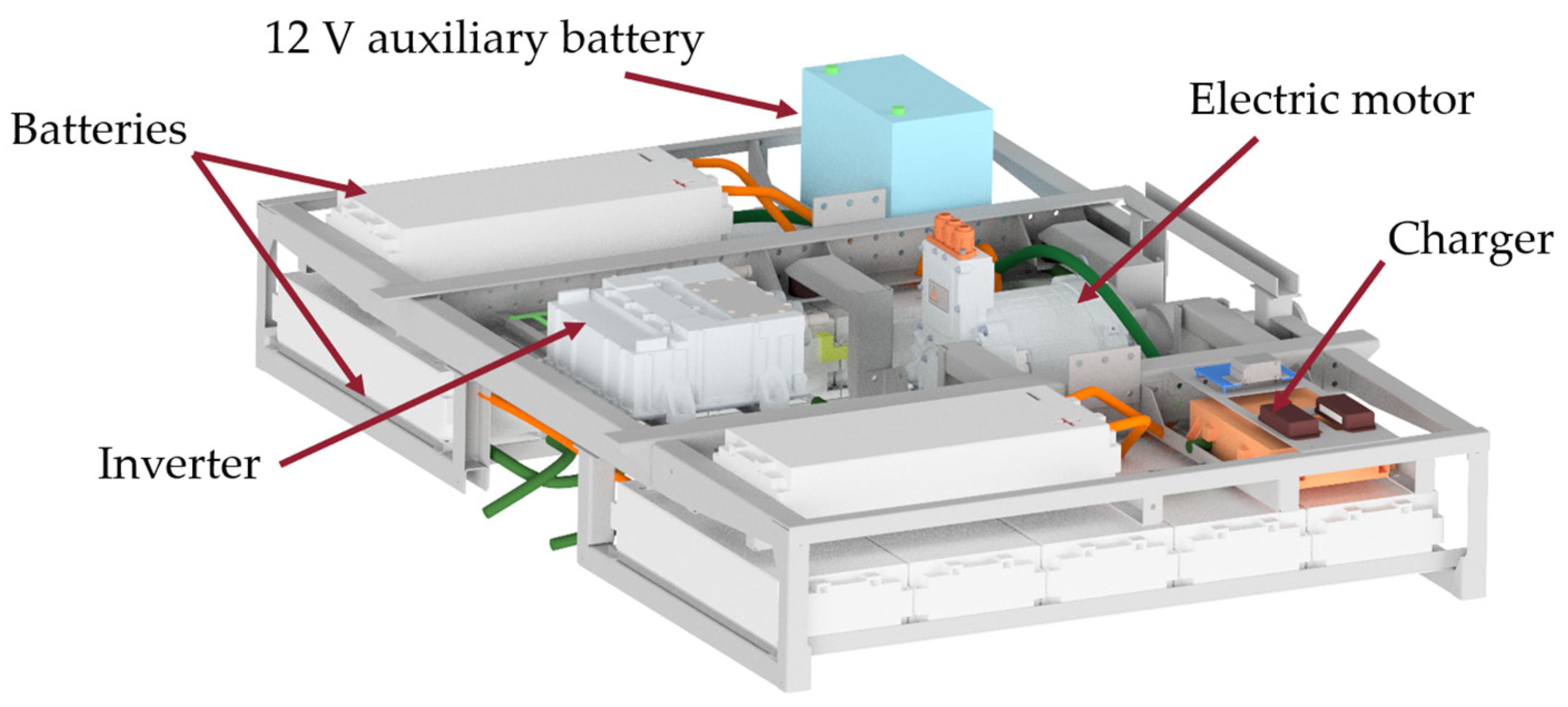
Figure 3 shows the general arrangement of these elements. The module is organized around a steel supporting structure that acts as both a frame and mounting surface. This structure incorporates attachment points that allow the assembly to be installed in different chassis configurations, either in rear or central position, without the need to redesign the system.
The electric motor and the reduction gear are located in the lower section, aligned with the drive shaft. Above this block are the battery modules and the liquid-cooling system, arranged to optimize the centre of gravity and ensure an adequate thermal-flow distribution. The electronic equipment—inverter, charger, and DC/DC converters—is mounted on an upper tray and connected to the thermal circuit through heat-exchange plates.
The structure incorporates internal channels for routing HV/LV wiring, as well as accessible inspection points. This organization allows the module to be handled as an autonomous unit, simplifies its installation in multistage manufacturing processes, and facilitates its certification as an ITU.
The result is a compact, orderly, and adaptable module capable of integrating all subsystems required for electric propulsion without compromising accessibility, safety, or overall versatility.

4.4. Verification of Performance: Modified WLTP Driving Cycle

The dynamic verification of the traction system was carried out through the simulation of a driving cycle based on the WLTP (Worldwide Harmonized Light Vehicles Test Procedure), adapted to the characteristics and regulatory limitations of N2-category industrial vehicles. The cycle to be performed depends on Power-to-Mass Ratio (PMR), defined as the ratio of the assigned vehicle’s power to the mass in running order, as well as its maximum speed, vmax. PMR, expressed in W/kg, categorises vehicles into three distinct classes:
  • Class 1: PMR ≤ 22 W/kg
  • Class 2: 22 W/kg < PMR ≤ 34 W/kg
  • Class 3: PMR > 34 W/kg
At this stage of the modular electric vehicle’s development, a mass in running order of 3000 kg and a peak power at the wheel of 117 kW were considered. In estimating this power, account was taken of both the motor’s and the battery system’s capacity to supply power, as well as the estimated efficiency of the systems involved. This results in a PMR of 39 W/kg. This places the vehicle in Class 3, well above the threshold value (PMR > 34 W/kg). Within Class 3, vehicles are further divided into two sub-classes based on their maximum speed, vmax.
  • Class 3a: vehicles with vmax < 120 km/h
  • Class 3b: vehicles with vmax ≥ 120 km/h
For this vehicle, the maximum achievable speed is below 120 km/h; therefore, it is categorised as a Class 3a vehicle. According to the regulations, the WLTP cycle for Class 3a consists of: a Low speed phase, a Medium speed phase, a High speed phase, and an Extra-High speed phase. The regulations also provide for a WLTCcity cycle for this vehicle class, which comprises only the Low and Medium speed phases. However, only the WLTP cycle has been utilised for the initial dimensioning of the prototype, as well as for the calculation of the vehicle’s range and performance.
Driveability issues may arise for certain vehicles in this class, particularly those with power-to-mass ratios close to the boundary between Class 2 and Class 3. These issues are primarily related to a lack of acceleration capacity during the Extra-High speed phase, where high speeds are combined with high acceleration rates. In such cases, the regulations provide for a cycle downscaling procedure to improve the vehicle’s driveability during the test.
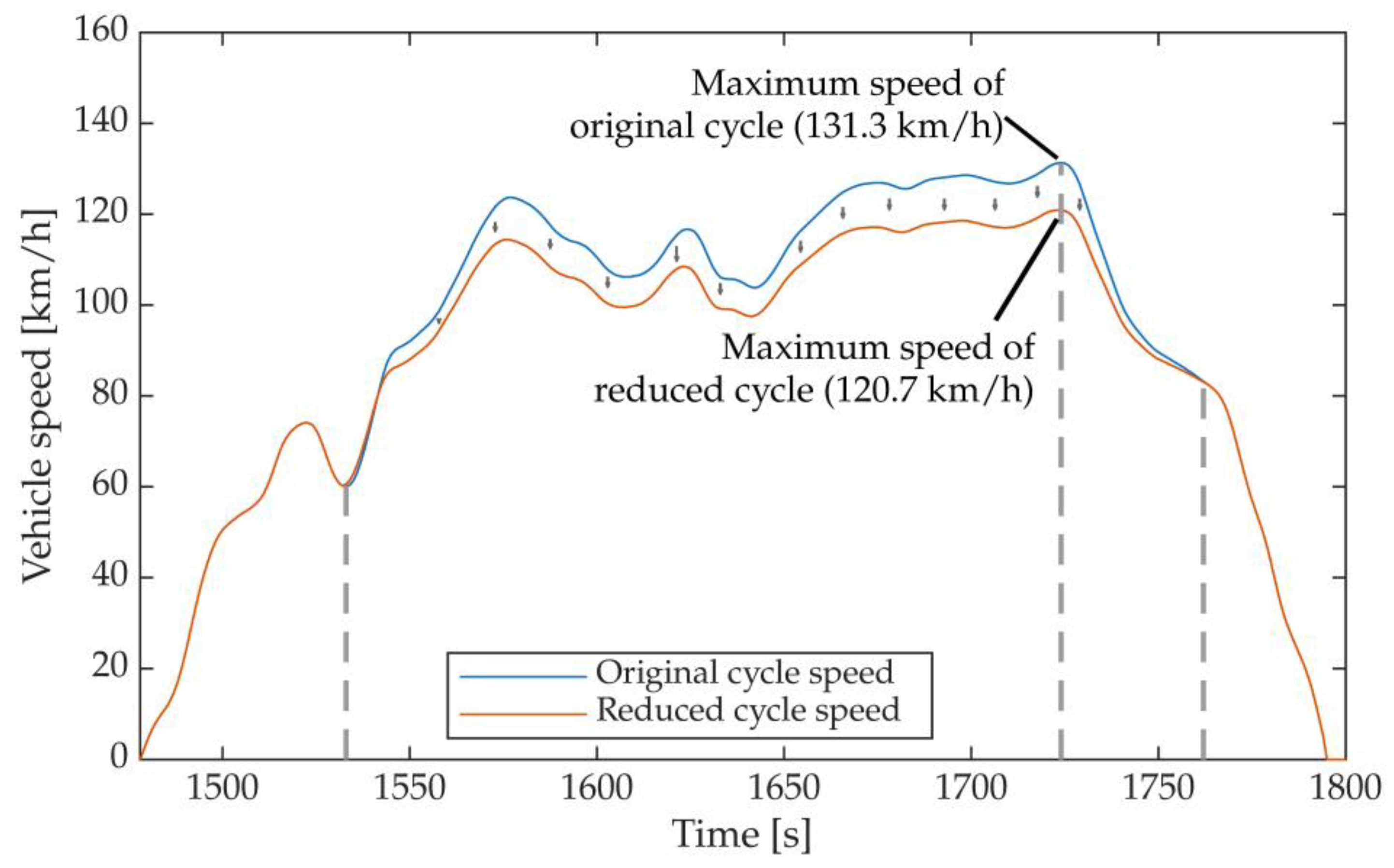
For Class 3 vehicles, downscaling is applied between second 1533 and second 1762, corresponding to the Extra-High speed phase. Firstly, the original acceleration at each time step of the cycle is calculated as:
a o r i g , i = v i + 1 v i 3.6
In this expression, vi is the vehicle speed, in km/h, en km/h; i is the time step between second 1533 and second 1762. The downscaling is first applied to the period between 1533 s and 1724 s, calculating the downscaled cycle speed as
v d c s , i + 1 = v d c s , i + a o r i g , i   1 f d s c   3.6
To determine the downscaling factor, fdsc, the power required to perform the cycle must be calculated. For a Class 3 vehicle, the maximum power demand in the original cycle occurs at second 1566, with a speed of 111.9 km/h and an acceleration of 0.5 m/s2. The downscaling coefficient is defined as a function of the ratio rmax, which is defined as the maximum required power during the cycle divided by the vehicle’s rated power.
r m a x = P r e q . m a x , i P v e h i c l e
For Class 3 vehicles, rmax is given by expression (7).
i f r m a x < 0.867 f d s c = 0 i f r m a x 0.867 f d s c = 0.588   f d s c 0.510
The regulation states that fdsc shall only be applied if it exceeds 0.010. For the vehicle studied in this work, rmax is 1.12 and fdsc is 0.149; therefore, the speed downscaling must be performed based on the acceleration capability.
Applying Equation (5), the downscaled speed vdcs,i at second 1533 is equal to the original cycle speed, vorig,i. However, at second 1724, the downscaled speed differs from the original. In the period between 1724 s and 1763 s, a correction factor fcorr is determined according to Equation (8), which ensures that at second 1762 the modified speed once again aligns with the original cycle speed.
f c o r r = v d c s , 1724 82.6 v o r i g , 1724 82.6
The value of 82.6 corresponds to the speed of the original cycle at second 1763, expressed in km/h. Using this factor fcorr, the downscaled speed is calculated as:
v d c s , i = v d c s , i 1 + a o r i g , i 1   f c o r r 3.6
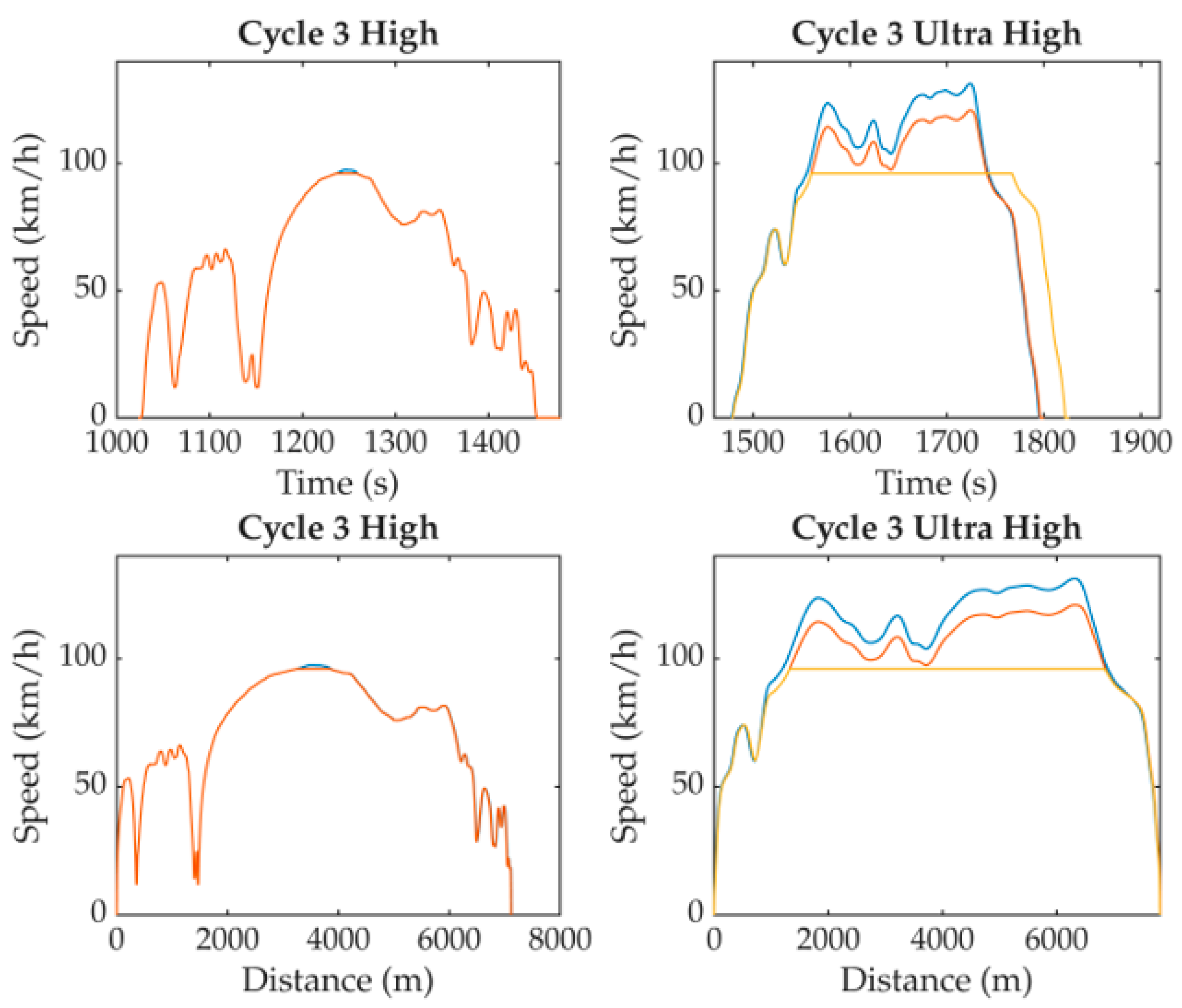
Figure 4 illustrates the cycle speed during the Extra-High phase for both the original and downscaled cycles. The maximum speed required of the vehicle during the cycle has decreased from 131.3 km/h for the original cycle to 120.7 km/h for the downscaled version.
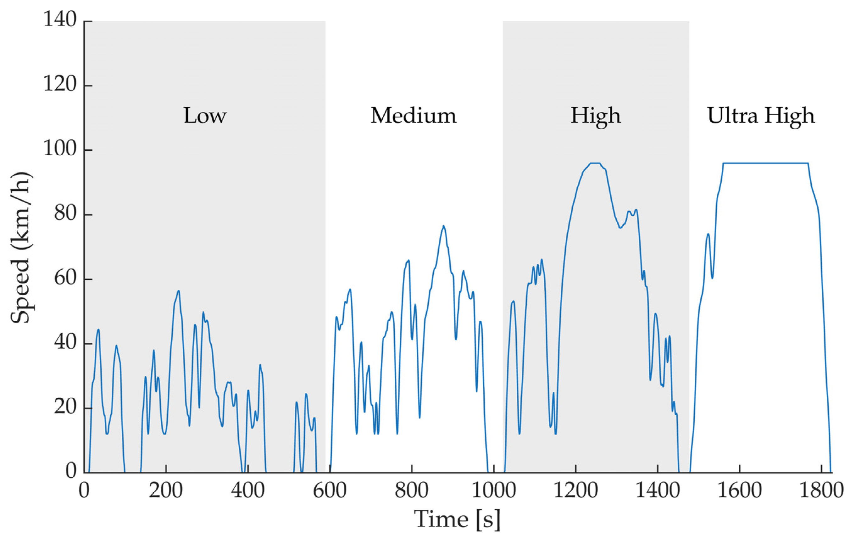
If, after applying the downscaling, the vehicle’s maximum speed remains lower than the maximum cycle speed, a cycle modification process is applied to cap the cycle’s peak speed. While the vehicle considered in this work can momentarily reach a speed of 126 km/h on a level road, the regulations define the maximum speed as that which the vehicle can maintain continuously for at least 30 min. Consequently, the WLTP cycle speed has been capped at 96 km/h, which is the maximum speed that can theoretically be sustained given the overall system limitations.
When capping the cycle speed, the cycle duration must be extended to ensure that the total distance travelled remains identical for both the downscaled and capped cycles. This adjustment increases the total duration of the cycle from the original 1800 s to approximately 2000 s. Table 4 shows the durations and distances covered in each phase, depending on the version of the cycle. Figure 5 shows the High and Extra-High speed phases for the original, downscaled, and capped cycles. It confirms that the distance travelled in the capped cycle is maintained (within a margin of ±26 m).
The modification of the cycle requires verifying that the vehicle can reproduce the accelerations demanded by the WLTP at every instant of the speed profile. To this end, a point-by-point evaluation was performed to determine whether the traction system provides the required torque, at the corresponding speed, to generate the acceleration prescribed by the cycle.
Additionally, the energy consistency of the modified cycle was assessed by verifying that, at every instant, the energy flow required to follow the WLTP profile does not exceed the power that can be supplied by the system components—battery, inverter, and motor. Complementarily, it was verified that, during regenerative-braking phases, the recovered power does not exceed the maximum charging capability of the battery nor the limits of the charge-management system, thus avoiding saturations or artefacts that could distort consumption calculations and range estimation.
Energy consumption due to traction has been converted to electrical consumption in the battery, considering the efficiencies of the transmission, motor, inverter, and batteries. To calculate the vehicle’s range, the energy consumption of other systems typical of commercial vehicles has also been considered: the cooling system, brake vacuum pump, air suspension, lighting, control systems and windscreen wipers. To this end, consumption figures have been obtained from the technical specifications of these components. In the case of components that are not switched on all the time, such as windscreen wipers or brake pumps, a usage factor has been applied to each consumption figure.

5. Results

This methodological procedure enables the estimation of the energy consumption and driving range of the traction system under representative dynamic conditions, forming the basis for the results analysis presented in the following section.

5.1. Validation of the Traction System

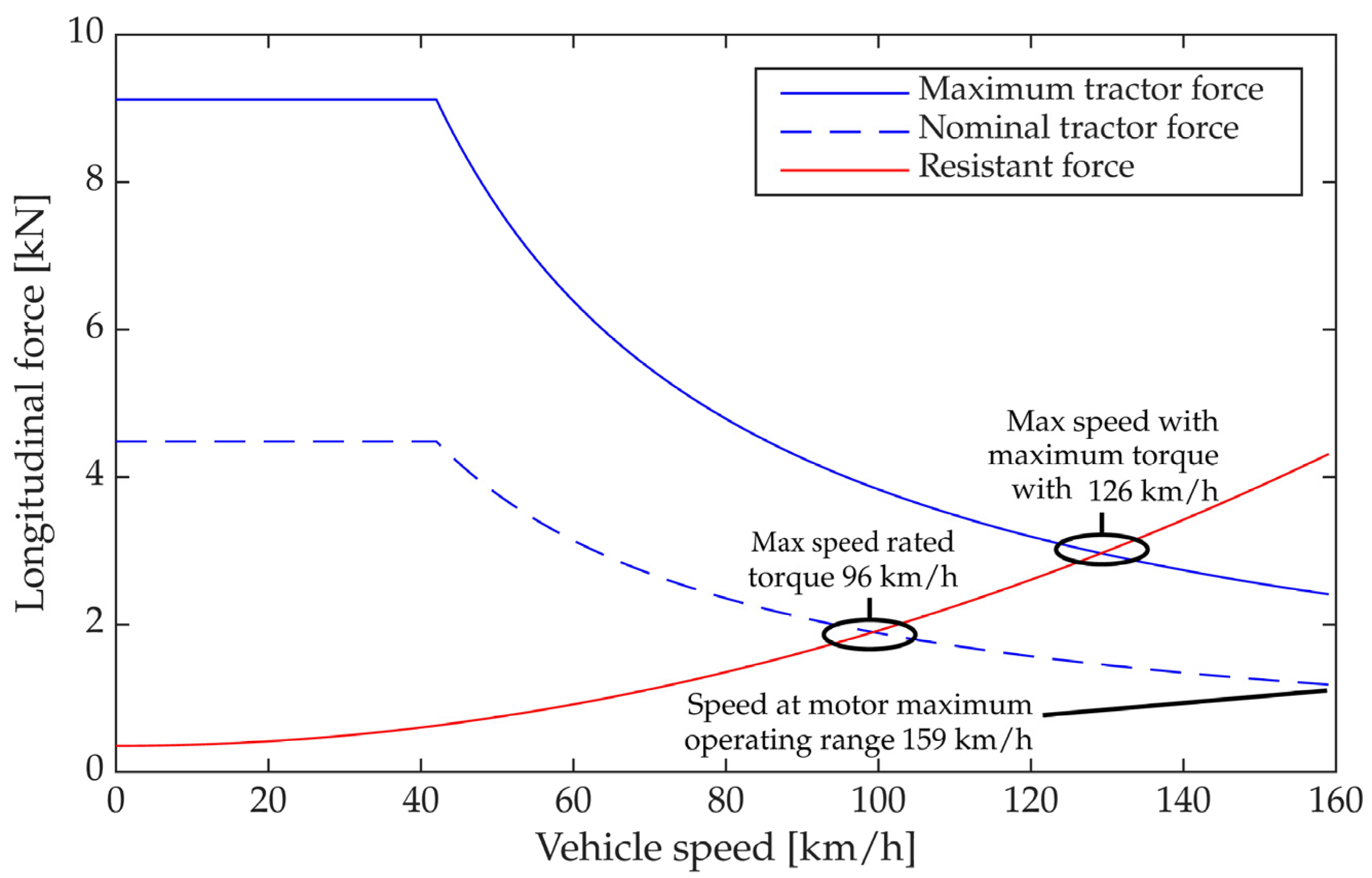
Before analysing the behaviour of the system during the modified WLTP cycle, the capability of the propulsion module to generate the required force under representative real-use limit conditions was evaluated. Figure 6 shows the comparison between the available tractive force at the wheels and the resistive forces to motion (rolling and aerodynamic) during flat-road driving with the vehicle loaded to its MTPM. At low speeds, the available tractive force is significantly higher than the total resistance, ensuring excellent starting performance and manoeuvrability in urban or industrial environments. At medium speeds, aerodynamic resistance becomes dominant, although it remains clearly below the available force.
A relevant aspect of this graph is the crossing point between both curves, which makes it possible to identify the maximum achievable speed as a function of the different motor torque curves. With the nominal torque curve, the selected transmission ratio, and taking into account the thermal limitations of the batteries, the theoretical maximum speed that the vehicle can maintain under those driving conditions is 96 km/h, a value above the regulatory limit of 90 km/h for N2 vehicles. This confirms that the system is oversized with respect to the legal requirement. If the maximum power curve is considered—maintainable for short intervals during overtaking manoeuvres—the maximum achievable speed increases to around 126 km/h. Finally, if only the maximum motor speed and the transmission ratio are considered, without accounting for resistive forces, the theoretical limit speed reaches 159 km/h, which corresponds to the end of the curves shown in Figure 6. This comparison demonstrates that the traction system provides a generous dynamic margin and that the actual speed limitation is imposed by regulation rather than by the capability of the powertrain.
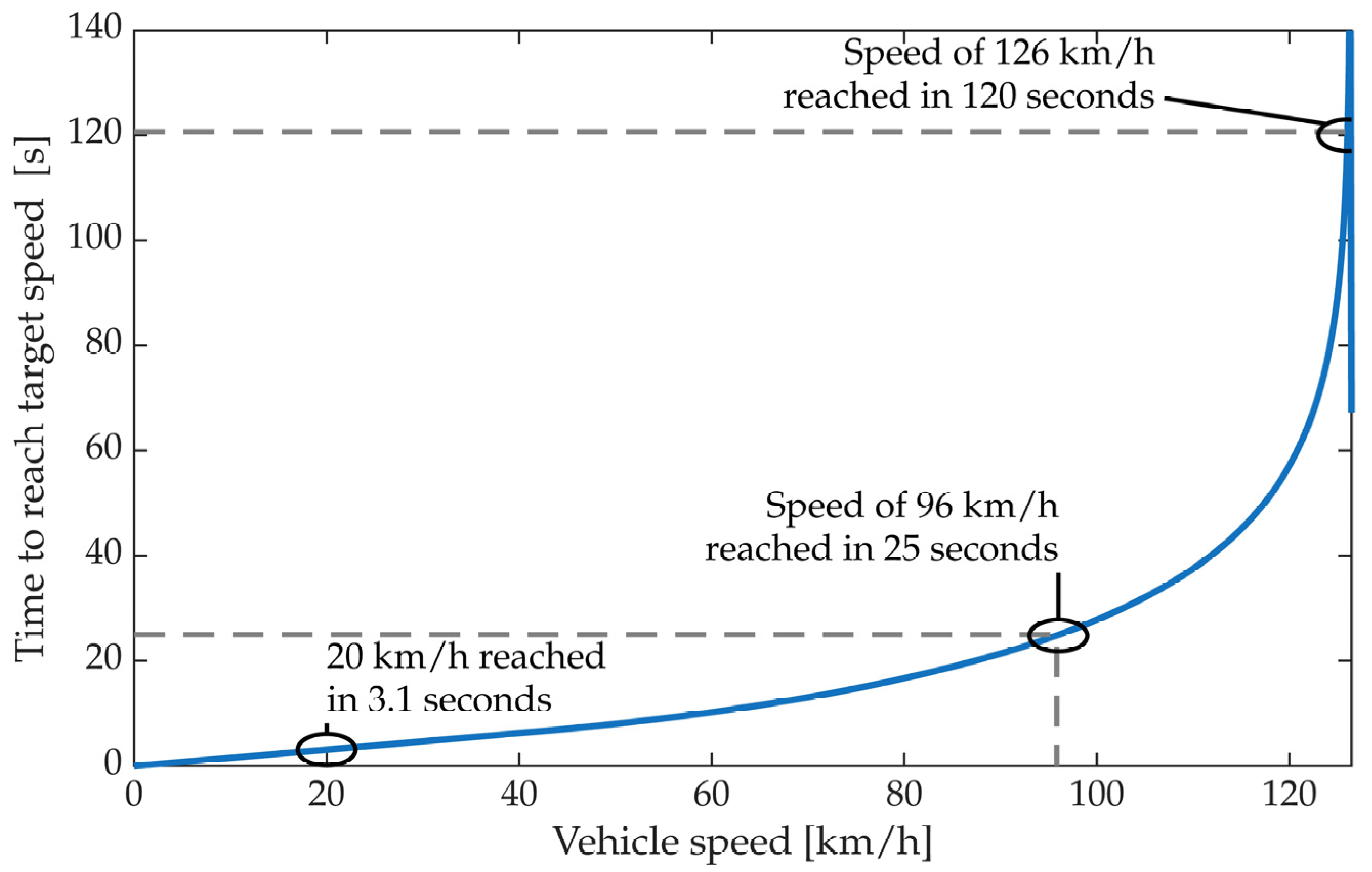
Figure 7 shows the evolution of the time required to reach different speeds on flat terrain and at the MTPM. The vehicle reaches 20 km/h within a few seconds, demonstrating an agile response during low-speed manoeuvres. The acceleration up to 6.3 s and 9.5 s falls within the typical range for electric industrial vehicles of equivalent power, while the rise to 80 km/h reflects the increasing influence of aerodynamic resistance. The time required to reach 96 km/h from standstill is 25 s, a value consistent with light industrial vehicles of similar characteristics.
With the selected traction system, the vehicle can momentarily reach speeds of up to 126 km/h. The time required to reach this speed is 120 s.
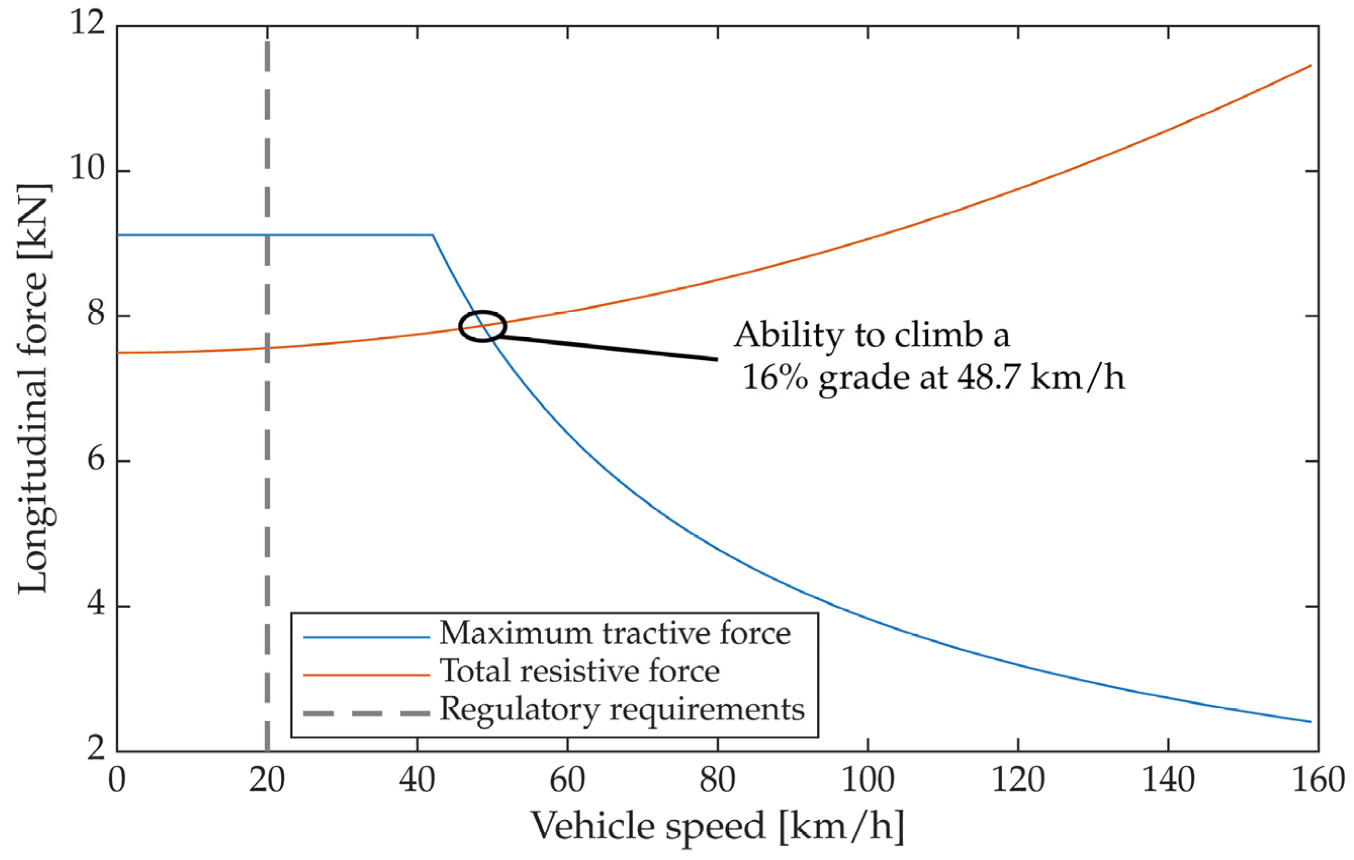
Figure 8 compares the available tractive force with the total resistive force on a 16% gradient with the vehicle loaded to its MTPM. At low speeds, the tractive force clearly exceeds the resistance, ensuring hill-start capability—an essential requirement in industrial and logistics applications. As speed increases, the resistive force grows due to the aerodynamic component, approaching the limit of the available tractive force. The system enables the vehicle to overcome 16% gradients at speeds below 48.7 km/h, well above the minimum threshold of 20 km/h required by regulation. The analysis of the tractive-force curve indicates that, in the absence of adhesion limitations, the vehicle could climb gradients of up to 26%. The system allows the vehicle to maintain low speeds on steep ramps, confirming its suitability for demanding operating scenarios.
Taken together, these results demonstrate that the MODULe traction system provides sufficient margin to propel the vehicle at MTPM on flat terrain, meet the acceleration requirements of the modified WLTP cycle, and operate on severe gradients without compromising safety or drivability. This validation confirms that the system is properly sized to undertake the modified WLTP cycle, whose results are presented in the following sections.

5.2. Speed Profile of the Modified WLTP Cycle

Based on the modified WLTP cycle described in Section 4.4, Figure 9 shows the speed profile used in the simulation of the traction system. The cycle preserves the sequential structure of the four original phases—Low, Medium, High, and Extra-High.
The resulting profile reflects a progressive transition from urban conditions with frequent starts and stops (Low phase), to segments of medium and sustained speed (Medium and High phases), ending with an Extra-High phase constrained by the maximum speed that the vehicle can maintain. This speed profile forms the basis for the analyses of acceleration, tractive force and power carried out in the following sections.

5.3. Longitudinal Acceleration in the Modified WLTP Cycle

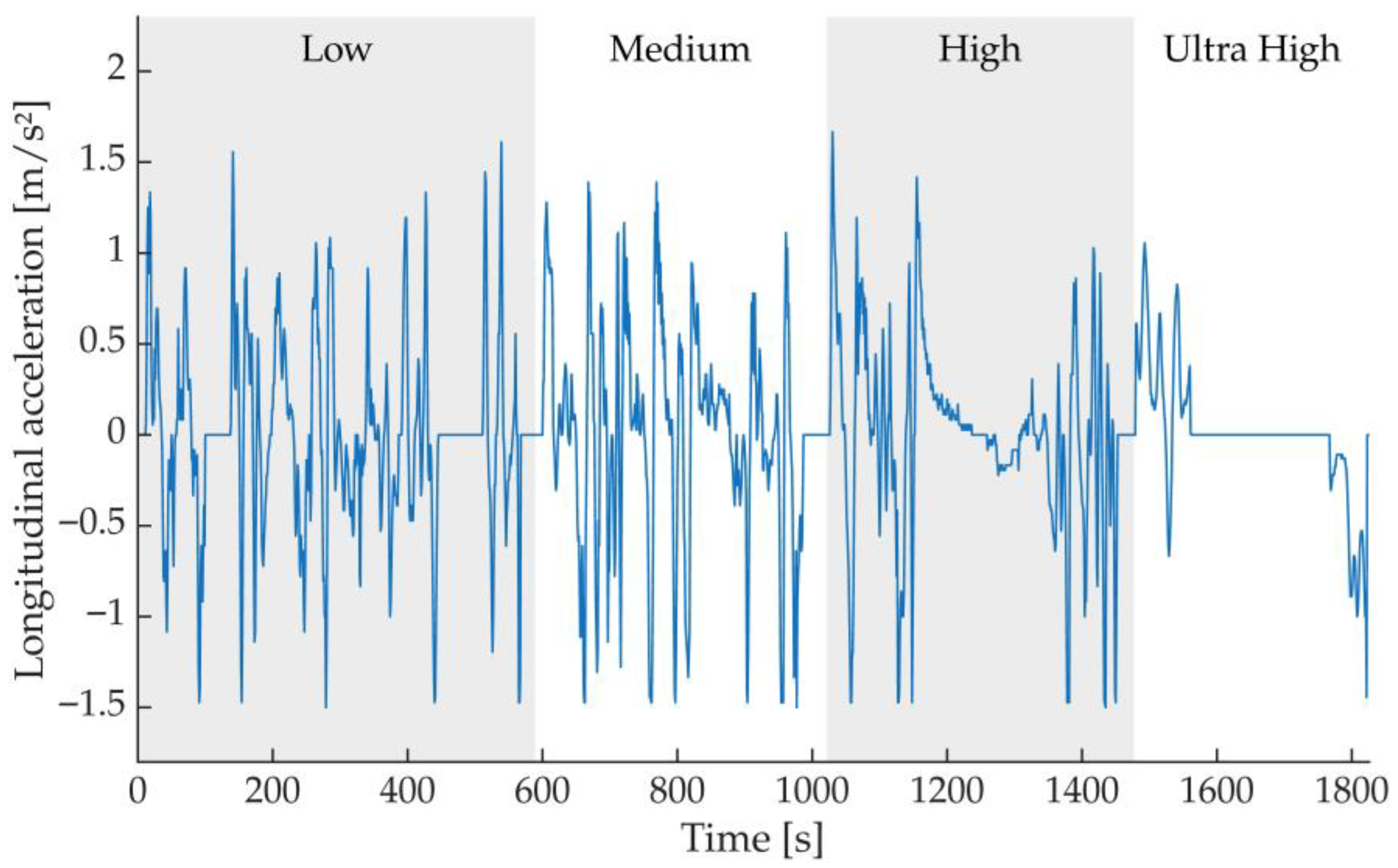
Figure 10 shows the longitudinal acceleration obtained from the time derivative of the speed curve. The cycle exhibits a characteristic alternation between acceleration and deceleration phases, particularly pronounced in the Low and Medium phases, where frequent starts and stops generate peaks of positive and negative acceleration. The High and Extra-High phases, limited to 96 km/h, show accelerations close to zero for most of their duration, due to zones where the speed remains constant or zones where the speed is high but varies little.
The peaks of positive acceleration have values of around 1.5 m/s2 and they coincide with the instants of highest torque demand at the wheels, while negative accelerations correspond to periods of regenerative braking. This behaviour is the direct origin of the tractive-force and power peaks analysed in Section 5.4.

5.4. Tractive Force, Power, and Energy Flow During the Modified WLTP Cycle

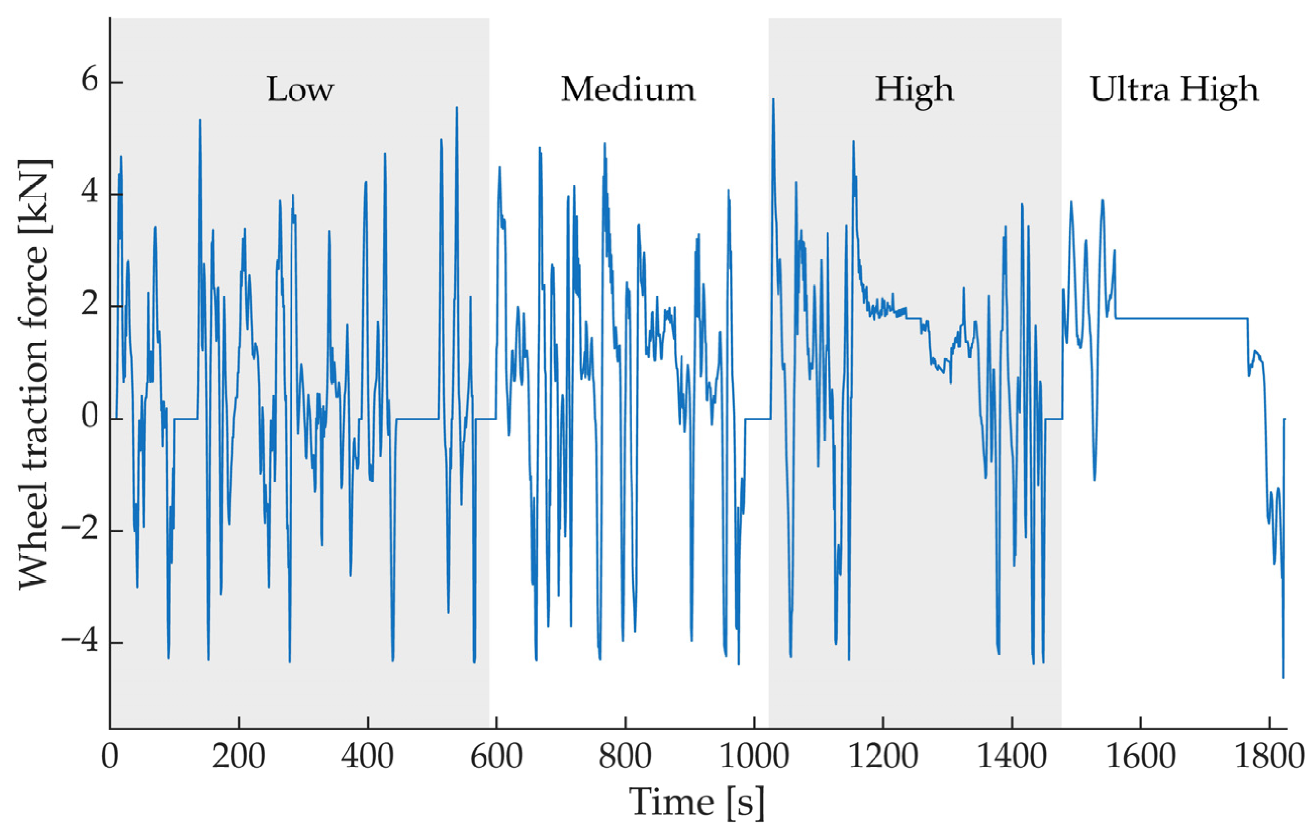
Based on the longitudinal acceleration obtained in Section 5.3 and the resistive forces defined in Section 5.1, Figure 11 shows the evolution of the required tractive force throughout the modified WLTP cycle. The force peaks coincide with the instants of highest acceleration in the Low and Medium phases, whereas in the High and Extra-High phases, there are areas where the force required remains close to the value needed to counteract the resistive forces generated by the constant speed.
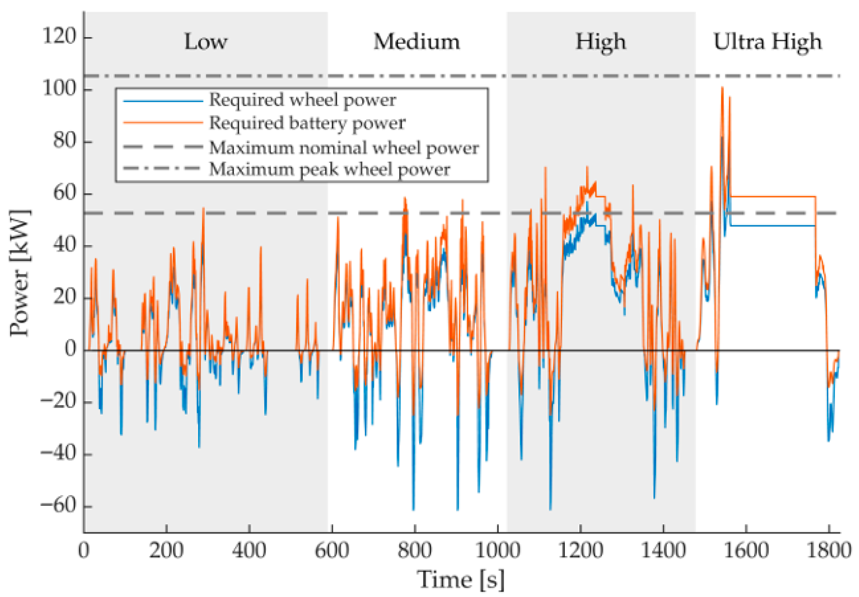
Figure 12 (blue line) shows the mechanical power at the wheels, calculated as the product of the tractive force and the instantaneous speed. The power peaks are concentrated in the periods of most intense acceleration, reaching values close to the maximum nominal power available at the wheels. At certain points during the High and Extra-High speed phase, it even momentarily exceeds the maximum nominal power at the wheels (grey dashed line), although it remains below the maximum peak power at the wheels (grey dash-dotted line).
The battery power flow, represented in Figure 12 (orange line), clearly distinguishes the periods of energy demand (positive power) from the intervals of regenerative braking (negative power). Regeneration occurs mainly in the Low and Medium phases, where decelerations are more frequent. Although the recovered energy is limited compared with the energy consumed, it contributes to reducing the net cycle consumption and improves the overall efficiency of the system.
Taken together, the evolution of the tractive force, mechanical power, and energy flow provides a complete characterisation of the vehicle’s dynamic behaviour during the modified WLTP cycle. These results form the basis for the statistical analysis of tractive effort presented in Section 5.5 and for the estimation of energy consumption and driving range developed in Section 5.6.

5.5. Distribution of Tractive Effort as a Function of Speed

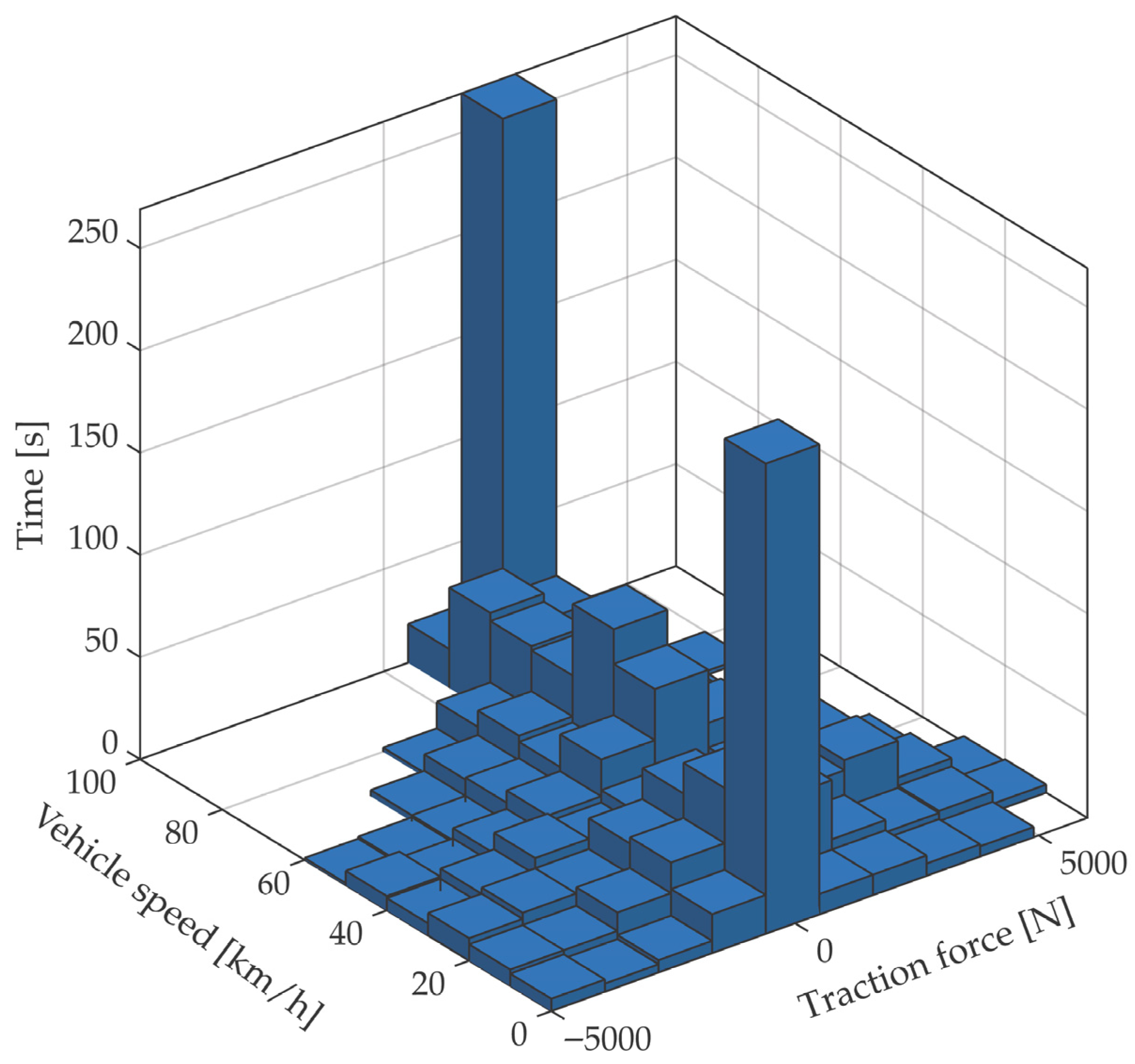
In addition to the time-domain analysis presented in Section 5.4, it is useful to examine the distribution of the required tractive effort as a function of speed, in order to identify the most frequent operating regimes during the modified WLTP cycle. Figure 13 shows the histogram of the required tractive force versus the instantaneous vehicle speed, constructed from the values obtained at each instant of the cycle.
The plot in Figure 13 shows that most of the operating time is concentrated at speeds between 30 and 70 km/h, where the required tractive force remains at moderate levels. This behaviour is consistent with the structure of the cycle, in which the Medium and High phases represent a significant proportion of the total duration. In these regions, aerodynamic resistance begins to play a relevant role, although it remains clearly below the maximum capability of the traction system. These driving speeds correspond, considering the selected gear ratio, to an engine speed of between 1500 rpm and 5300 rpm, which is a range where an electric motor with the characteristics of the one selected operates at high efficiency.
At low speeds, particularly below 20 km/h, peaks of tractive effort appear, associated with the starts and sharp accelerations of the Low speed phase. At the opposite end, at speeds above 80 km/h, the force required is close to the force needed to maintain the maximum cruising speed under steady-state conditions.
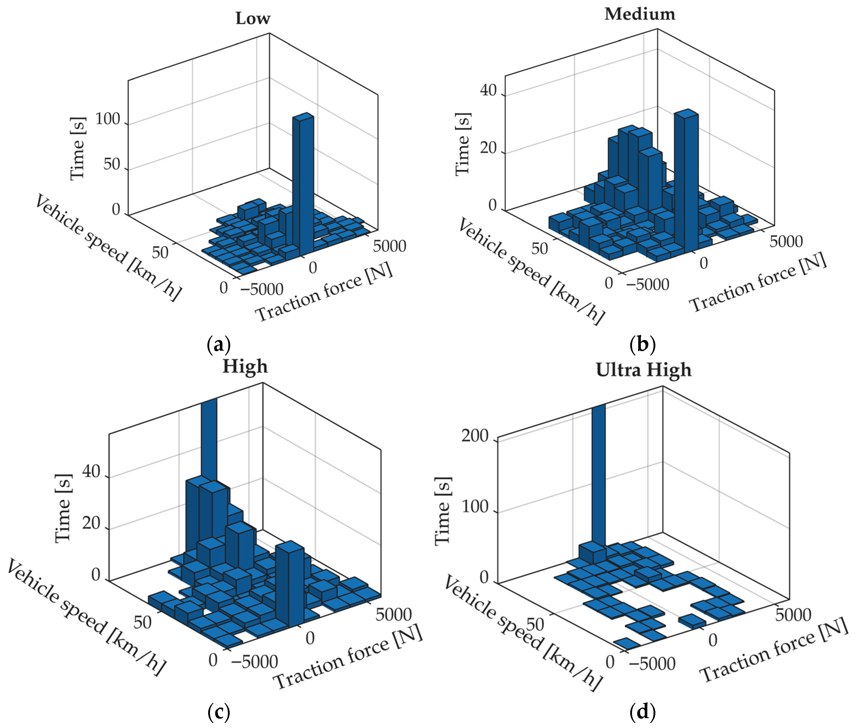
To complement the global analysis, Figure 14 presents the distribution of tractive effort as a function of speed and time for each of the phases of the modified WLTP cycle. The Low phase concentrates the most intense effort peaks at low speed, whereas the Medium and High phases exhibit a more homogeneous distribution. The Extra-High phase shows a concentration of effort around the maximum speed of the capped cycle. This phase-wise decomposition makes it possible to identify the most demanding operating regimes and provides key information for optimising the control of the traction system.
Taken together, the distribution of tractive effort makes it possible to identify the most representative operating ranges of the modified WLTP cycle and provides essential information for estimating energy consumption and driving range, analysed in Section 5.6.

5.6. Distribution of Wheel and Battery Power

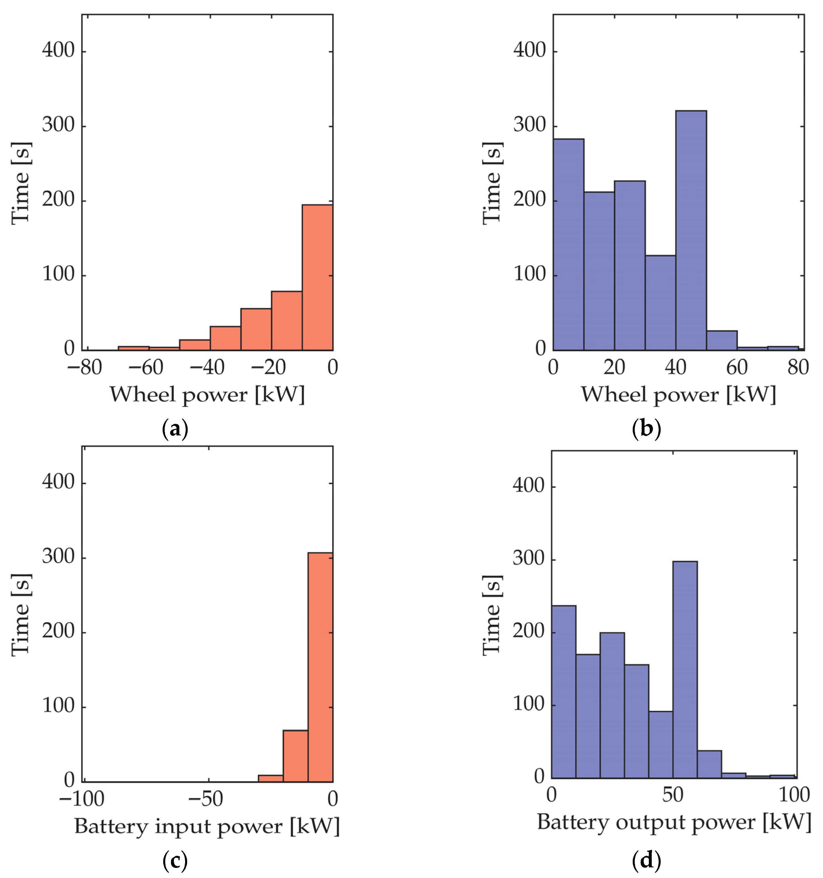
To analyse the energy behaviour of the traction system during the modified WLTP cycle, the distribution of wheel power and battery power has been evaluated as a function of accumulated time. Figure 15 presents four sub-figures, each corresponding to a different operating mode: power inflow and outflow at the wheels, and power inflow and outflow at the battery.
Figure 15a,b show the distribution of wheel power. Figure 15a represents the recovered wheel power (negative values), associated with periods of regenerative braking. Most of the operating time is concentrated around power levels close to 0 kW, indicating that energy recovery occurs predominantly within moderate ranges compatible with the system’s absorption capability. Figure 15b shows the wheel power output (positive values), corresponding to traction. The distribution is broader and exhibits a maximum around 50 kW, reflecting that the system operates more frequently at moderate power levels during propulsion.
Figure 15c,d represent the battery power. Figure 15c shows the battery power inflow (regeneration). The distribution is concentrated near 0 kW, confirming that most of the recovered energy remains within the admissible charging limits of the battery. Figure 15d shows the battery power outflow, that is, the energy supplied to the traction system. This distribution is broader and presents a peak around 50 kW, consistent with the energy demand observed during acceleration and sustained-speed segments.

5.7. Energy Consumption and Estimated Driving Range

To calculate the energy consumption associated with the modified WLTP cycle, the battery power flow was integrated over the entire simulation, considering both discharge periods and regenerative events. During this process, it was verified that the energy recovered through regenerative braking did not exceed the maximum admissible charging power of the battery at any time. As shown in the sub-figures of Figure 14, most regenerative events are concentrated below 10 kW, allowing virtually all recovered energy to be utilised without saturating the storage system.
The total energy required to complete the modified WLTP cycle was 10.44 kWh, which corresponds to a specific consumption of 44.99 kWh/100 km associated exclusively with traction. This value lies within the expected range for medium-duty electric industrial vehicles operating in urban environments, where low-speed phases and frequent accelerations predominate.
An additional 6.45 kWh/100 km was added to account for the vehicle’s auxiliary systems, including HVAC, ventilation, power steering, lighting, cooling, and electronic control systems. The resulting total consumption is therefore 51.4 kWh/100 km, a representative value for a realistic operating scenario of an N2-category industrial vehicle.
Considering the usable energy storage capacity of the MODULe system, equal to 82.27 kWh, the estimated driving range of the vehicle under the modified WLTP cycle is 160 km. This range comfortably meets the operational requirement defined for logistics and public-service applications, enabling full work shifts without the need for intermediate recharging. Consequently, both the traction system and the battery capacity are adequate for urban and industrial operations with usage profiles similar to the analysed cycle.
Table 5 summarises the main energy results obtained for the modified WLTP cycle.

6. Discussion

6.1. Technical Applicability of the MODULe System to Industrial Vehicles

The results obtained from the simulations allow the operating range of vehicles in which the MODULe system can be integrated to be defined with precision. The nominal power of 90 kW, the torque available at the rear axle, and the energy capacity of 82.27 kWh make it compatible with N1 and N2-category vehicles, particularly those intended for urban delivery, municipal services, infrastructure maintenance, street cleaning, or goods transport in industrial environments.
The module has been sized to maintain sustained speeds of 96 km/h, overcome 16% gradients at full load, and achieve driving ranges above 160 km, covering the typical operational requirements of urban and peri-urban fleets. In addition, its architecture allows rear-mounted, central, or axle-mounted configurations, facilitating integration into chassis-cab platforms or vehicles with interchangeable bodies.

6.2. Integration into Existing Vehicles: Retrofit and Progressive Electrification

Figure 16 shows the propulsion module as an ITU, designed for installation in industrial vehicles without the need to redesign the entire powertrain. This configuration enables retrofit strategies in existing fleets, replacing the diesel power unit with an electric system suitable for type approval.
Figure 17 illustrates the integration of the MODULe system into an N2-category chassis-cab, developed within the framework of a municipal-truck electrification project. The module is installed on the original frame, preserving the mass distribution and the structural mounting points. The multiphase architecture allows the vehicle’s functional bodywork—such as toolboxes, tanks, or loading platforms—to be retained, while adapting the electrical system without compromising safety or operational efficiency.
This approach is particularly useful in urban contexts where the electrification of public and commercial fleets faces budget constraints, emission regulations, and interoperability requirements. The modularity of the system facilitates technical validation, reduces homologation costs, and enables a progressive transition towards electric mobility without the need to replace the entire vehicle.

6.3. Technical Constraints for Structural Integration

The feasibility of integrating the MODULe system into existing vehicles depends on several technical factors:
  • Availability of space on the chassis to accommodate the complete module.
  • Compatibility with rigid or independent axles and with existing suspension systems.
  • Adaptability of mounting points and supporting substructures.
  • Mass distribution and its impact on the vehicle’s center of gravity.
  • Accessibility for maintenance and protection against vibrations and impacts.
These criteria have been considered in the design of the module, which incorporates a reinforced load-bearing structure, internal channels for wiring, technical trays for power electronics, and distributed cooling systems. Validation through simulation and testing confirms that the system can operate autonomously and safely in real configurations.

6.4. Industrial Advantages of the Modular Approach

Adopting a modular architecture offers significant advantages in terms of scalability, maintenance, and industrial deployment:
  • Reduction of development and validation times.
  • Reuse of the module across different platforms and configurations.
  • Simplified maintenance through interchangeable units.
  • Scalability of power and energy capacity depending on the application.
  • Reduced homologation costs through certification of ITUs.
These characteristics position the MODULe system as a viable solution for the electrification of urban and industrial fleets, both in new vehicles and in retrofit processes. The flexibility of the design, regulatory compliance, and structural adaptability reinforce its applicability in real-world energy-transition scenarios.

7. Conclusions

The conceptual development of the MODULe system has demonstrated the technical and regulatory feasibility of a modular electric-propulsion architecture oriented towards urban and industrial vehicles. The integration of the main subsystems—motor, inverter, batteries, cooling system, and control unit—into a compact technical module effectively addresses the challenges of scalability, flexibility, and homologation associated with the electrification of commercial fleets.
Validation against a modified WLTP driving cycle has confirmed that the selected components respond appropriately to the dynamic demands of real operating environments, while maintaining electrical safety, EMC, and thermal stability. This validation methodology, based on speed, acceleration, and tractive-force profiles, provides a solid foundation for the technical sizing of the system and its adaptation to different vehicle configurations.
The proposed modular approach facilitates homologation through small-series certification and individual approval, in accordance with Regulation (EU) 2018/858 and the applicable UNECE regulations. The possibility of certifying the module as an ITU enables its subsequent integration into incomplete vehicles without repeating critical tests, significantly reducing development time and cost.
Overall, the MODULe system represents a robust technical and regulatory solution for the transition towards sustainable, efficient, and adaptable industrial mobility. Its potential application in public services, urban logistics, and specialised transport positions it as a versatile platform for the progressive electrification of vehicle fleets in urban and interurban contexts.
In addition to the practical implementation of the prototype, the study provides methodological elements that may be useful for future research on modular electric platforms. The sizing criteria, the regulatory-oriented integration approach and the WLTP-based performance evaluation offer a structured framework that can be adapted to other vehicle categories or modular architectures. Future work will focus on extending the experimental validation, refining the thermal–energy management strategies and analysing the behaviour of the module under different operational profiles.

Future Work

Once the conceptual design phase of the MODULe system has been completed, the next stages of the project will focus on the manufacturing and validation of functional prototypes to demonstrate the technical feasibility of the concept under real operating conditions. This phase will include the development of complete traction and energy-storage units, integrated into vehicle configurations representative of urban and industrial applications.
In parallel, the exploration of hybridisation technologies is envisaged, incorporating alternative energy-storage systems such as hydrogen and fuel cells. This line of work responds to recent technological developments and to sustainability strategies that promote energy diversification in transport. The possibility of combining different technologies within the same vehicle—for example, batteries and a fuel cell—will enable extended driving range, improved operational efficiency, and adaptation to environments with diverse energy infrastructures.
Structural and thermal testing of the designed modules is also planned, using finite-element models and bench tests to validate mechanical strength, thermal management, and EMC. These tests will be essential to ensure that the modules can be certified as ITUs in accordance with electrical-safety requirements and applicable UNECE regulations.
Finally, preparatory actions for the industrialisation of the system will be initiated, defining multiphase manufacturing protocols, integration standards for bodybuilders, and short-series homologation strategies. This phase will require collaboration with industrial partners interested in adopting the technology, as well as the planning of technology-transfer and dissemination activities within the industrial sector.

8. Patents

This work is supported by two Spanish utility models, a national industrial property right comparable to a patent but focused on protecting technical innovations with shorter development cycles. The first protection is the utility model ES 1 229 869 U, titled “Vehículo modular eléctrico de transporte y reparto de mercancías”, owned by Universidad Miguel Hernández and filed on 30 January 2019, published on 23 May 2019 [27]. This utility model establishes the conceptual basis for a modular electric vehicle designed for urban logistics, featuring configurable load areas and a flexible structural layout.
The developments presented in this article are also related to the utility model ES 1 311 746 U, titled “Dispositivo modular de propulsión eléctrica acoplable al chasis de un camión”, filed in 2024 and owned by Universidad Miguel Hernández [28]. This second protection focuses on a modular electric propulsion device conceived as an ITU, enabling its integration into multistage approval processes and its installation in different industrial vehicle platforms.
Together, these two Spanish utility models provide the legal and technological foundation for the modular propulsion architecture described in this work, reinforcing its applicability, scalability, and industrial relevance.

Author Contributions

Conceptualization, M.S.-L., D.A.-L., F.J.S.-P. and A.R.N.-A.; methodology, M.S.-L.; validation, D.A.-L. and F.J.S.-P.; investigation, M.S.-L. and A.R.N.-A.; resources, M.S.-L.; data curation, D.A.-L.; writing—original draft preparation, A.R.N.-A.; writing—review and editing, M.S.-L. and D.A.-L.; supervision, M.S.-L.; project administration, M.S.-L.; funding acquisition, M.S.-L. All authors have read and agreed to the published version of the manuscript.

Funding

This work is part of the MODULe project, funded by the Valencian Innovation Agency (AVI) within the programme for the Valorisation and Transfer of Research Results to Companies 2022 (reference INNVA1/2022/33).

Data Availability Statement

The data supporting the findings of this study are openly available in the MODULe project repository at: https://github.com/IVBDM-UMH/MODULe, accessed on 29 January 2026.

Acknowledgments

The authors acknowledge the collaboration of the staff of the Centro Integrado de Formación Profesional La Torreta de Elche, as well as the technical and logistical support provided by the Instituto Tecnológico de la Energía (ITE) during the electrical system design and component selection. The participation of PIMESA, Desguaces Mora, Grupo Volund, Odyssey Robotics and LAVEL Servicios Técnicos e Innovación is also gratefully recognized, as their involvement was essential for the development and validation of the proposed concept. The authors further acknowledge the administrative assistance from the Institute for Engineering Research (I3E) of the Universidad Miguel Hernández during the preparation of the experimental setup and documentation. During the preparation of this manuscript, the authors used Microsoft Copilot (2025 version) exclusively for language-related assistance, including clarification of wording and translation of specific paragraphs. No generative artificial intelligence was used to create scientific content, perform data analysis, design the study, or interpret results. The authors have reviewed and edited all language-related output and take full responsibility for the final content of this publication.

Conflicts of Interest

The authors declare no conflicts of interest. The funders had no role in the design of the study; in the collection, analyses, or interpretation of data; in the writing of the manuscript; or in the decision to publish the results.

Abbreviations

The following abbreviations are used in this manuscript:
BMSBattery Management System
CANController Area Network
EMCElectromagnetic Compatibility
EVElectric Vehicle
HVHigh Voltage
ITUIndependent Technical Unit
LVLow Voltage
MROMass in Running Order
MTPMMaximum Technically Permissible Mass
OBCOn-Board Charger
PMRPower-to-Mass Ratio
TPMLMTechnically Permissible Maximum Laden Mass
UNECEUnited Nations Economic Commission for Europe
WLTPWorldwide Harmonised Light-Duty Vehicles Test Procedure

References

  1. Cai, W.; Wu, X.; Zhou, M.; Liang, Y.; Wang, Y. Review and development of electric motor systems and electric powertrains for new energy vehicles. Automot. Innov. 2021, 4, 3–22. [Google Scholar] [CrossRef]
  2. Hussein, H.M.; Ibrahim, A.M.; Taha, R.A.; Rafin, S.M.S.H.; Abdelrahman, M.S.; Kharchouf, I.; Mohammed, O.A. State-of-the-art electric vehicle modeling: Architectures, control, and regulations. Electronics 2024, 13, 3578. [Google Scholar] [CrossRef]
  3. Ferreira, J.C.; Esperança, M. Enhancing sustainable last-mile delivery: The impact of electric vehicles and AI optimization on urban logistics. World Electr. Veh. J. 2025, 16, 242. [Google Scholar] [CrossRef]
  4. Darwish, A. A modular step-up DC/DC converter for electric vehicles. Energies 2024, 17, 6305. [Google Scholar] [CrossRef]
  5. Darwish, A.; Elgenedy, M.A.; Williams, B.W. A review of modular electrical sub-systems of electric vehicles. Energies 2024, 17, 3474. [Google Scholar] [CrossRef]
  6. Kardasz, M.R.; Kazerani, M. Design and experimental evaluation of a scaled modular testbed platform for the drivetrain of electric vehicles. Vehicles 2023, 5, 830–845. [Google Scholar] [CrossRef]
  7. Kraus, D.; Baumann, D.; Vučinić, V.; Sax, E. Cloud-enabled reconfiguration of electrical/electronic architectures for modular electric vehicles. World Electr. Veh. J. 2025, 16, 111. [Google Scholar] [CrossRef]
  8. Ferreira, M.A.S.; Begazo, M.F.T.; Lopes, G.C.; Oliveira, A.F.; Colombini, E.L.; Simões, A.S. Drone reconfigurable architecture (DRA): A multipurpose modular architecture for unmanned aerial vehicles (UAVs). J. Intell. Robot. Syst. 2020, 99, 517–534. [Google Scholar] [CrossRef]
  9. Schneider, R.; Kockisch, R.; Clauß, M.; Ambrosius, V. Modular systems for sustainable electrified powertrains. ATZ Worldw. 2021, 123, 48–53. [Google Scholar] [CrossRef]
  10. Schindewolf, M.; Guissouma, H.; Sax, E. Analysis and modeling of future electric/electronic architectures for modular vehicle concepts. In Proceedings of the 21st Internationales Stuttgarter Symposium; Springer Vieweg: Wiesbaden, Germany, 2021; pp. 32–46. [Google Scholar] [CrossRef]
  11. Robinette, D. Electric motor and transmission integration for light-duty electric vehicles: A 2023 benchmarking perspective and component sizing for a fleet approach. Vehicles 2023, 5, 1167–1195. [Google Scholar] [CrossRef]
  12. Savio, F.M.; Dharmalingam, K.; Chakkarapani, K. A dual-mode interleaved bridgeless converter with improved efficiency for electric vehicle battery charger. J. Electr. Eng. Technol. 2025, 21, 1641–1660. [Google Scholar] [CrossRef]
  13. Cao, J. Reduce EV Cost and Improve Drive Range by Integrating Powertrain Systems. Texas Instruments Technical Article. 2020. Available online: https://www.ti.com/lit/pdf/sszt170 (accessed on 12 January 2026).
  14. Pan, C.; Li, Y. Koopman model predictive control of an integrated thermal management system for electric vehicles. J. Dyn. Syst. Meas. Control 2023, 145, 051005. [Google Scholar] [CrossRef]
  15. Moreno, G.; Narumanchi, S.; Feng, X.; Anschel, P.; Myers, S.; Keller, P. Electric-drive vehicle power electronics thermal management: Current status, challenges, and future directions. J. Electron. Packag. 2022, 144, 011004. [Google Scholar] [CrossRef]
  16. European Parliament and Council of the European Union. Regulation (EU) 2018/858 of the European Parliament and of the Council of 30 May 2018 on the Approval and Market Surveillance of Motor Vehicles and Their Trailers, and of Systems, Components and Separate Technical Units Intended for Such Vehicles, Amending REGULATIONS (EC) No 715/2007 and (EC) No 595/2009 and Repealing Directive 2007/46/EC. Off. J. Eur. Union 2018, 151, 1–218. [Google Scholar]
  17. United Nations Economic Commission for Europe (UNECE). UN Regulation No. 100—Uniform Provisions Concerning the Approval of Vehicles with Regard to Specific Requirements for the Electric Power Train. Off. J. Eur. Union 2024, L 1955, 1–88. Available online: http://data.europa.eu/eli/reg/2024/1955/oj (accessed on 29 January 2026).
  18. Roth, A. Certification of High-Voltage Batteries According to ECE R100; Battery University GmbH: Karlstein, Germany, 2023; Available online: https://batteryuniversity.eu/en/standards/ece-r100 (accessed on 12 January 2026).
  19. Cerne, S. New Mandatory Safety Testing Requirements for Electric Vehicle Batteries under R100. TÜV SÜD White Paper. 2024. Available online: https://www.tuvsud.com (accessed on 12 January 2026).
  20. ISO 26262; Road Vehicles—Functional Safety. International Organization for Standardization (ISO): Geneva, Switzerland, 2018.
  21. United Nations Economic Commission for Europe (UNECE). Regulation No. 154—Uniform Provisions Concerning the Approval of Passenger Cars and Light Commercial Vehicles with Regard to Emissions and Energy Consumption (WLTP). Off. J. Eur. Union 2022, L 290, 1–625. Available online: http://data.europa.eu/eli/reg/2022/2124/oj (accessed on 29 January 2026).
  22. European Commission. Worldwide Harmonised Light-Duty Vehicles Test Procedure (WLTP) and Real Driving Emissions (RDE). Regulation (EU) 2017/1151—Summary. Available online: https://eur-lex.europa.eu (accessed on 12 January 2026).
  23. IEC 61851-1; Electric Vehicle Conductive Charging System—Part 1: General Requirements. International Electrotechnical Commission (IEC): Geneva, Switzerland, 2017.
  24. ISO 11898-1:2024; Road Vehicles—Controller Area Network (CAN)—Part 1: Data Link Layer and Physical Coding Sublayer. ISO: Geneva, Switzerland, 2024.
  25. FMVSS 305; Electric-Powered Vehicles: Electrolyte Spillage and Electrical Shock Protection. U.S. Department of Transportation: Washington, DC, USA, 2011.
  26. SAE J1772; Electric Vehicle and Plug-in Hybrid Electric Vehicle Conductive Charge Coupler. SAE International: Warrendale, PA, USA, 2017.
  27. GB/T 18384; Electric Vehicles—Safety Requirements. SAC: Beijing, China, 2020.
  28. GB/T 18487; Electric Vehicle Conductive Charging System. SAC: Beijing, China, 2015.
  29. GB/T 31467; Lithium-Ion Traction Battery Packs and Systems for Electric Vehicles—Specifications and Test Methods. SAC: Beijing, China, 2015.
  30. Forti, A.W.; Ramos, C.C.; Muniz, J. Integration of design structure matrix and modular function deployment for mass customization and product modularization: A case study on heavy vehicles. Int. J. Adv. Manuf. Technol. 2023, 125, 1987–2002. [Google Scholar] [CrossRef]
  31. Aiello, G.; Quaranta, S.; Certa, A.; Inguanta, R. Optimization of urban delivery systems based on electric assisted cargo bikes with modular battery size. Energies 2021, 14, 4672. [Google Scholar] [CrossRef]
  32. Sánchez Lozano, M.; Simón Portillo, F. Propuesta de nuevas arquitecturas para vehículos comerciales eléctricos ligeros. In Actas del XXII Congreso Nacional de Ingeniería Mecánica; Oficina Española de Patentes y Marcas: Madrid, Spain, 2018; pp. 773–780. [Google Scholar]
  33. Sánchez Lozano, M.; Simón Portillo, F.J.; Abellán López, D.; Navarro Arcas, A.R. Vehículo Modular Eléctrico de Transporte y Reparto de Mercancías (Modelo de Utilidad nº ES1229869); Oficina Española de Patentes y Marcas: Madrid, Spain, 2019. [Google Scholar]
  34. Sánchez Lozano, M.; Simón Portillo, F.J.; Abellán López, D.; Navarro Arcas, A.R. Dispositivo Modular de Propulsión Eléctrica Acoplable al Chasis de un Camión (Modelo de Utilidad nº ES1311746); Oficina Española de Patentes y Marcas: Madrid, Spain, 2024. [Google Scholar]
  35. Farzam Far, M.; Miljavec, D.; Manko, R.; Pippuri-Mäkeläinen, J.; Ranta, M.; Keränen, J.; Kinder, J.; Vukotić, M. Modular and scalable powertrain for multipurpose light electric vehicles. World Electr. Veh. J. 2023, 14, 309. [Google Scholar] [CrossRef]
  36. Van Gemert, C.G. Modular Vehicle Architecture. EP1628854B1, 7 November 2012. [Google Scholar]
  37. Hagemann, G.S.; Hoelzel, G.; Kristl, R. Modulares Nutzfahrzeug mit austauschbaren Funktionsmodulen. DE19926607A1, 15 March 2001. [Google Scholar]
  38. Bisser, M.; Pedrotti, W.; Sakrzewski, S. Commercial Vehicle and Modular System for a Commercial Vehicle. DE102013004837A1, 21 March 2013. [Google Scholar]
  39. Byrnes, P.; Lockerbie, M. Modular Electric Vehicle System. US20160129958A1, 19 December 2017. [Google Scholar]
  40. Hinov, N.; Punov, P.; Gilev, B.; Vacheva, G. Model-Based Estimation of Transmission Gear Ratio for Driving Energy Consumption of an EV. Electronics 2021, 10, 1530. [Google Scholar] [CrossRef]
  41. Yildirim, M.; Kurt, S. Effect of Different Types of Electric Drive Units on the Energy Consumption of Heavy Commercial Electric Vehicles. World Electr. Veh. J. 2022, 13, 92. [Google Scholar] [CrossRef]
  42. Ma, S.; Jiang, M.; Tao, P.; Song, C.; Wu, J.; Wang, J.; Deng, T.; Shang, W. Temperature effect and thermal impact in lithium-ion batteries: A review. Prog. Nat. Sci. Mater. Int. 2018, 28, 653–666. [Google Scholar] [CrossRef]
Figure 1. Examples of customizable configurations: (a) Rear-mounted traction module with a central cargo area. (b) Centrally mounted traction module with two cargo areas. (c) Possibility of accessing the cargo area directly from the cabin.
Vehicles 08 00091 g001
Figure 2. CAD representation of one of the dual-motor alternative initially evaluated, showing the independent transmission arrangement and battery placement above the axle.
Vehicles 08 00091 g002
Figure 3. General arrangement of the traction-module components.
Vehicles 08 00091 g003
Figure 4. Downscaling of the Extra-High speed phase of the WLTP cycle for a Class 3a vehicle based on the acceleration capacity of the designed vehicle. The arrows indicate the maximum speed reached in each cycle, and the dotted vertical lines mark the interval where the downscaling procedure is applied.
Vehicles 08 00091 g004
Figure 5. Comparison between the original WLTP cycle, the reduced cycle, and the capped cycle. Speed profile as a function of time and distance. The blue line represents the original WLTP cycle, the orange line the reduced cycle, and the yellow line the capped cycle.
Vehicles 08 00091 g005
Figure 6. Longitudinal force balance under flat-road conditions for a vehicle loaded to its MTPM. Comparison between maximum and nominal tractive force of the tractor and the total resistive force as a function of vehicle speed.
Vehicles 08 00091 g006
Figure 7. Time required to reach a given speed under flat-road conditions for a vehicle loaded to its MTPM.
Vehicles 08 00091 g007
Figure 8. Longitudinal force curves under a 16% road gradient for a vehicle loaded to its MTPM. Comparison between tractive force and total resistive force as a function of vehicle speed.
Vehicles 08 00091 g008
Figure 9. Vehicle speed profile during the modified WLTP cycle.
Vehicles 08 00091 g009
Figure 10. Longitudinal acceleration profile during the modified WLTP cycle.
Vehicles 08 00091 g010
Figure 11. Required wheel traction force during the modified WLTP cycle for a vehicle loaded to its MRO.
Vehicles 08 00091 g011
Figure 12. Mechanical power at the wheel and battery power flow during the modified WLTP cycle for a vehicle loaded to its MRO.
Vehicles 08 00091 g012
Figure 13. Three-dimensional histogram of required traction force as a function of vehicle speed and time during the modified WLTP cycle.
Vehicles 08 00091 g013
Figure 14. Distribution of required traction force by phase of the modified WLTP cycle. (a). Low phase. (b). Medium phase. (c). High phase. (d). Extra-High phase.
Vehicles 08 00091 g014
Figure 15. Histograms of power distribution during the modified WLTP cycle. (a). Regenerative power at the wheel. (b). Propulsive power at the wheel. (c). Battery input power. (d). Battery output power.
Vehicles 08 00091 g015
Figure 16. Compact propulsion module.
Vehicles 08 00091 g016
Figure 17. Integration of the module within a municipal-truck electrification project.
Vehicles 08 00091 g017
Table 1. Comparison between existing modular vehicle architectures and the proposed traction-module approach.
ArchitectureModule DecompositionMotor LocationBattery LocationTraction–Cargo SeparationDedicated Traction Module 1
Proposed architectureCab, traction module, one or more cargo modulesAxle-mounted motor inside traction moduleInside traction module (over axle)Independent traction module, with optional load on topYes
EP1628854B1 [36]Cab + combined rear drive-and-load moduleRear in-wheel motorsOver rear wheel archesDrive and load combinedNo
DE19926607A1 [37]Cab, front drive module, passenger module, rear drive moduleFront and rear drive modulesIn energy modules/over axlesPassenger module between drive modulesNo
DE102013004837A1 [38]Cab, cargo module, rear drive moduleRear drive moduleOver rear wheel archesCargo separate, drive integrated in chassisNo
US2016129958A1 [39]Cab, multiple powered axle modules, deck modulesPowered axle modulesIn powered modules/along chassisDeck modules separateNo
1 A “dedicated traction module” is defined as a self-contained unit that integrates all propulsion subsystems, remains independent from the vehicle chassis, and is suitable for certification as an ITU.
Table 2. Geometric, aerodynamic, rolling-resistance and transmission characteristics of the vehicle.
CategoryParameterValue
Masses and dimensionsMTPM4500 kg
MRO3000 kg
Width2.3 m
Height3 m
Aerodynamics rnFrontal area (A)5.52 m2
Cx0.6
Tyresrn0.342 m
Slip ratio ( κ )0.05
fr0.012
rc0.328 m
re0.325 m
Transmissioni04.2
nT0.9
Table 3. Characteristics of the selected motor.
CategoryValue
Brand and modelZonic 180
Maximum torque360 Nm
Nominal torque177 Nm
ω b a s e (base speed)4100 rpm
ω m a x (maximum speed)12,000 rpm
Maximum power180 kW
Nominal power90 kW
Reduction gear (igear)2.2
Voltage Range270–420 V
Table 4. Phases of the WLTP Class 3 Cycle (original, reduced, and capped cycle).
PhaseEnvironment DescriptionDuration Original CycleDuration Downscale CycleDuration Capped Cycle
Low speedUrban traffic, frequent starts and stops590 s/
3095 m
590 s/
3095 m
590 s/
3095 m
Medium speedSuburban traffic, moderate speeds433 s/
4721 m
433 s/
4721 m
433 s/
4721 m
High speedInterurban traffic, sustained speeds455 s/
7124 m
455 s/
7124 m
455 s/
7117 m
Extra-High speedMotorway, high-speed conditions323 s/
8254 m
323 s/
7815 m
349 s/
7810 m
Total 1800 s/
23,194 m
1800 s/
22,754 m
1827 s/
22,743 m
Table 5. Summary of results for the modified WLTP cycle.
ConceptValue
Total cycle energy10.44 kWh
Distance travelled22.7 km
Traction consumption44.99 kWh/100 km
Auxiliary consumption6.45 kWh/100 km
Total consumption51.4 kWh/100 km
Driving range160 km
Disclaimer/Publisher’s Note: The statements, opinions and data contained in all publications are solely those of the individual author(s) and contributor(s) and not of MDPI and/or the editor(s). MDPI and/or the editor(s) disclaim responsibility for any injury to people or property resulting from any ideas, methods, instructions or products referred to in the content.