Article

Automated Mid-Surface Mesh Reconstruction for Automotive Plastic Parts Based on Point Cloud Registration


1
National key Laboratory of Advanced Vehicle Integration and Control, FAW Global R&D Center, Changchun 130013, China
2
CATARC (Tianjin) Automotive Engineering Research Institute Co., Ltd., Tianjin 300000, China
*
Author to whom correspondence should be addressed.
Vehicles 2026, 8(4), 89; https://doi.org/10.3390/vehicles8040089
Submission received: 1 January 2026 / Revised: 24 March 2026 / Accepted: 7 April 2026 / Published: 10 April 2026

Abstract

In automotive Computer-Aided Engineering (CAE), the fidelity of high-quality shell element meshes is fundamentally governed by the accuracy of mid-surface geometry extraction. Conventional manual extraction for complex automotive plastic components is labor-intensive, error-prone, and often compromises mesh quality. To address these issues, this paper proposes an automated mid-surface mesh reconstruction method based on point cloud registration, establishing an integrated framework comprising “Multimodal Registration—Displacement Binding—Surface Correction.” Using a source part with an ideal mid-surface as a template, the method integrates Random Sample Consensus (RANSAC) and Iterative Closest Point (ICP) for rigid registration and Coherent Point Drift (CPD) for non-rigid registration to achieve high-precision alignment between the target and source outer-surface point clouds. Subsequently, a K-Nearest Neighbor (K-NN) search-based displacement binding mechanism smoothly transfers the outer-surface displacement field to the source mid-surface point cloud. Following position correction and surface smoothing, a complete and high-quality target mid-surface mesh is generated. Experimental results on typical plastic snap-fit components demonstrate that the normal projection error between the generated mid-surface and the manually refined “gold standard” mesh is less than 0.05 mm. The processing time per component is approximately 38 s, representing an efficiency improvement of over 73% compared to manual extraction using commercial CAE software. This method effectively mitigates common issues such as mid-surface distortion and feature loss, offering a high-precision, fully automated solution for automotive CAE pre-processing.

1. Introduction

In modern automotive design, Computer-Aided Engineering (CAE) leverages numerical simulation to significantly shorten product development cycles, reduce testing costs, and enhance structural performance [1,2]. Finite Element Analysis (FEA), a cornerstone of CAE, is widely utilized in structural strength, Noise, Vibration, and Harshness (NVH), fatigue durability, and lightweight design [3]. Given the prevalence of thin-walled structures in vehicles—such as body panels and plastic brackets—discretization using shell elements is the industry standard due to its accuracy in capturing thin-walled mechanical behavior and computational efficiency [4]. Shell modeling essentially involves the dimensional reduction of 3D solids into a theoretical neutral layer, or “mid-surface.” The geometric accuracy and topological integrity of this mid-surface directly dictate the quality of the mesh and the reliability of the final simulation [5]. Therefore, extracting high-quality mid-surfaces from complex Computer-Aided Design (CAD) solid models is a critical bridge between geometric design and simulation analysis [6,7]. Inaccurate extraction can lead to mesh distortion and spurious stress concentrations, severely undermining the reliability of engineering decision-making [8]. However, automating the generation of ideal mid-surfaces from complex solids remains a significant challenge [9].
Currently, mid-surface extraction primarily relies on geometric reasoning algorithms, including Medial Axis Transform (MAT) [10], Chordal Axis Transform (CAT) [11], Face Pairing [12], and Virtual Decomposition [13,14]. While these methods are relatively mature for handling regular, uniform-thickness metal stampings [2], they exhibit significant limitations when applied to components with complex geometric topologies. Mounir et al. [15] noted that existing algorithms are often restricted to predefined feature sets, necessitating the prior removal of detailed features. Similarly, Ma’s research [6] indicates a lack of versatility and flexibility in processing complex scanning features. Although the solid deflation method proposed by Sheen et al. offers improvements, it remains constrained by the complexity of feature interactions [16]. Further studies by Qin et al. [17] and Jiang et al. [18] confirm that the robustness of traditional methods declines significantly when dealing with occlusions or non-rigid deformations. In summary, traditional methods suffer from three major drawbacks: First, they have a weak capability for identifying and retaining local fine features (e.g., small fillets, snap-fits, thin ribs), often resulting in the loss or erroneous simplification of key mechanical characteristics [19]. Second, they exhibit poor adaptability to complex surfaces; core algorithms based on offsets and Boolean operations struggle to robustly handle non-uniform wall thicknesses and free-form surfaces, frequently leading to topological errors such as geometric distortion, surface discontinuity, or self-intersection at feature junctions [20]. Finally, the level of automation is low; processing complex models often requires extensive manual intervention for parameter tuning and patch repair, resulting in low efficiency, heavy reliance on operator experience, and a lack of reproducibility [21].
These challenges are particularly acute in the mid-surface extraction of automotive plastic parts (e.g., snap-fits, interior trims, and brackets). Such components typically possess high geometric complexity, characterized by thin walls, complex spatial surfaces, multi-level snap structures, and local thickness variations caused by bosses or mounting pillars [22]. These features make traditional geometric reasoning methods highly susceptible to severe topological errors, such as holes and missing patches, rendering the extracted mid-surface meshes unusable for simulation [23]. Even the graphical tools within mainstream commercial CAE software (e.g., ANSYS Design Modeler, version 2023 R2) face bottlenecks of unstable results and cumbersome manual interaction when processing such parts, which severely constrains the efficiency of CAE pre-processing [24].
To overcome the limitations of traditional geometric methods, researchers have begun exploring new approaches based on 3D point cloud data. As the foundation of reverse engineering and 3D reconstruction, point cloud registration technology has demonstrated broad application potential across various fields [25,26], providing technical support for model reconstruction based on scanned data in CAE. Registration can be categorized into rigid and non-rigid types based on the nature of deformation [27]. While rigid registration can resolve global pose alignment, Huang et al. [28] pointed out that its assumption of isometric deformation is inapplicable to the non-uniform deformations observed in reality. Therefore, non-rigid registration must be introduced to estimate complex deformation fields. Although non-rigid registration has shown increasing robustness in handling large deformations, noise, and outliers [17,29], its adaptability to local deformations and topological structures requires further enhancement [30,31,32].
In recent years, advancements in deep learning—such as feature matching-based methods like PPFNet [33] and 3DSmoothNet [34], as well as end-to-end approaches like FlowNet3D [35] and PRNet [36]—have enabled the precise capture of local and global point cloud features [37,38]. These methods focus on improving robustness against occlusion [39], large deformations [40], and outliers [17,21], significantly elevating the accuracy and automation of registration. However, existing advanced point cloud registration methods largely focus on the global alignment of object outer surfaces, lacking a specific deformation migration mechanism for the mid-surface, which represents the internal geometric layer. In particular, there is a lack of specialized research and validation on how to ensure feature fidelity after deformation for critical fine features (such as snap-fits) in automotive plastic parts.
Addressing the challenges of automation and accuracy in processing the complex geometry of automotive plastic parts, this paper proposes an automated mid-surface mesh reconstruction method based on point cloud registration. Distinct from traditional geometric reasoning technical routes, this study innovatively introduces non-rigid point cloud registration technology to construct an integrated solution of “Multimodal Point Cloud Registration—Displacement Field Binding—Mid-surface Geometry Correction”. This method aims to achieve displacement migration and adaptive correction of mid-surface geometric information through high-precision alignment between the outer-surface point clouds of the source and target parts, thereby realizing the automated reconstruction of high-quality mid-surface meshes.
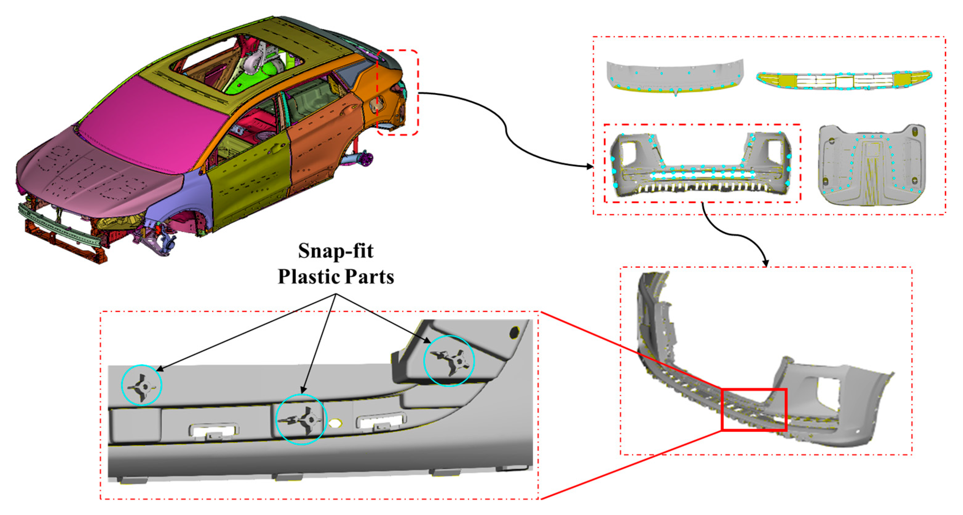
Plastic components are extensively used in automotive interiors, exteriors, and structural applications, such as bumpers, door panels, instrument panels, and battery pack casings, due to their lightweight properties, design flexibility, and corrosion resistance, as shown in Figure 1.
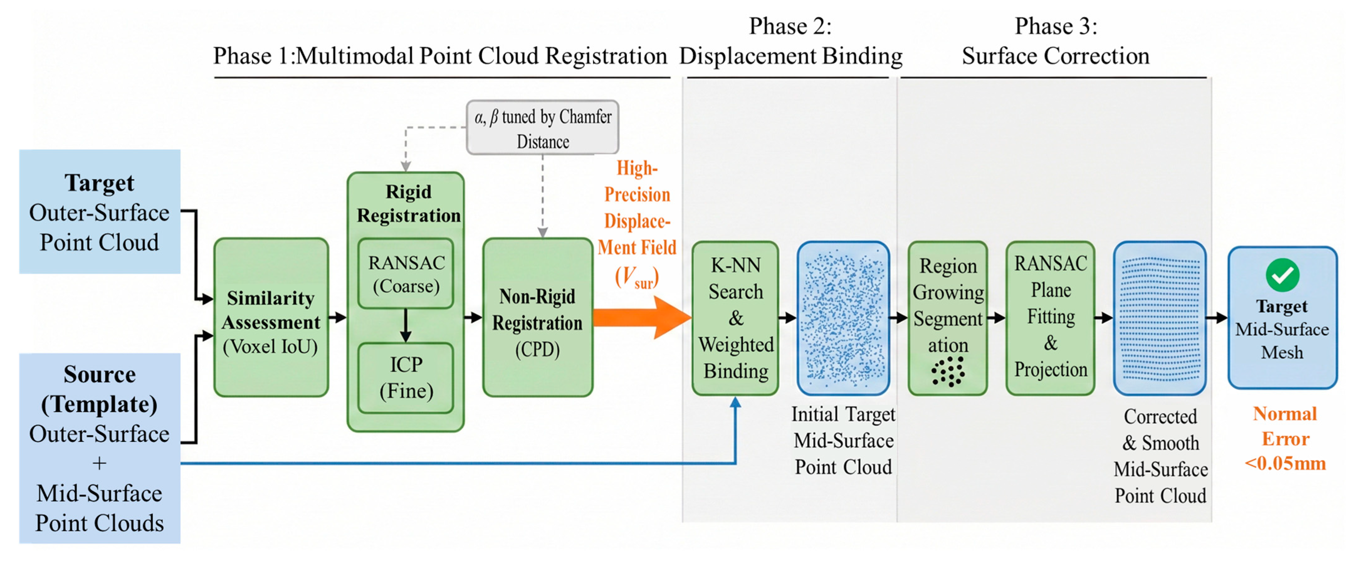
In this study, we propose an automated method for reconstructing mid-surface meshes of automotive plastic parts based on point cloud registration. The core mechanism is the generation of the target mid-surface point cloud via “displacement migration”. The method utilizes a source component with complete geometric information, comprising a high-precision outer-surface point cloud and a corresponding standard mid-surface point cloud, as a reference template. For a target component with similar topology but local geometric variations, a multi-step point cloud registration process is first employed to obtain a high-precision displacement field mapping the source outer surface to the target outer surface. The displacement field is then transferred to the source standard mid-surface point cloud, driving it to deform adaptively to match the geometric features of the target outer surface, thereby generating the target mid-surface point cloud. This workflow avoids complex direct mid-surface extraction operations on the target component, enabling efficient and automated mid-surface mesh generation. The specific technical roadmap is illustrated in Figure 2.
The remainder of this paper is organized as follows: Section 2 details the overall framework and key technical route of the automated mid-surface mesh reconstruction method; Section 3 proposes a position correction algorithm based on region growing and RANSAC fitting to resolve local distortion and jitter issues; Section 4 systematically validates the geometric accuracy, processing efficiency, and robustness of the method using typical automotive plastic snap-fits, and discusses the advantages and limitations of the method; and Section 5 concludes the paper and outlining future research directions.

2. Mid-Surface Point Cloud Generation

2.1. Similarity Assessment for Snap-Fits

A standardized source point cloud database is first established by selecting typical automotive plastic snap-fits as source components. Standard outer-surface and mid-surface mesh models are created using commercial CAE software, and vertex coordinates are extracted via the software’s application programming interface (API) to automatically convert these mesh models into point cloud data. By processing multiple sets of source components in batches, a library of “outer surface–mid-surface” point cloud correspondences is constructed. This data conversion process, implemented via the CAE software API, forms a closed technical loop that supports both mesh-to-point-cloud conversion and the subsequent reconstruction of the generated target mid-surface point cloud into a CAE-software-readable format.
For a given target component, only the outer-surface point cloud (containing 3D coordinate information) is required as input. The system automatically matches it against the source library to determine if a suitable template exists. The matching process consists of two main steps: 3D coordinate flattening and overlap quantification.

2.1.1. 3D Coordinate Flattening

A voxel-based discretization strategy is adopted to enable efficient spatial overlap assessment. To circumvent computationally intensive continuous 3D distance calculations, the continuous space is quantized into a voxel grid. Each point is assigned a unique 1D voxel index, converting the problem into a comparison of discrete representations, thereby greatly enhancing computational efficiency for the set operations required for Intersection over Union (IoU) calculation.
First, spatial voxelization is performed: using the union of the minimum bounding boxes of the target and current source point clouds as the spatial boundary, the 3D space is uniformly discretized into cubic voxels with a side length of 1 mm. Next, 1D index mapping is applied: for any 3D point (x, y, z) in the target or source point cloud, global positional differences are eliminated via coordinate normalization. The point’s offsets (x, y, z) relative to the bounding box boundaries in three directions are calculated, and its 3D voxel index is determined by flooring these values, which is given as follows:
( i , j , k ) = ( x d , y d , z d ) ,
where i, j, k are the voxel indices in the x, y, z directions, respectively, and d is the distance from the 3D point to the bounding box boundary, defined as:
d = ( x ) 2 + ( y ) 2 + ( z ) 2 .
Finally, the 3D indices are mapped to a 1D feature index using equation:
h = i + j S x + k S x S y ,
where Sx, Sy, Sz represent the number of voxel divisions in the x, y, z directions, respectively. This process retains the spatial distribution characteristics of the point cloud while converting the 3D matching problem into a rapid 1D feature comparison.

2.1.2. Similarity Assessment Based on Intersection over Union (IoU)

Following dimensionality reduction, the spatial overlap between the target and source point clouds is quantified using the 3D IoU to assess similarity. Based on the voxel mapping results, voxel sets Vtar and Vsrc are constructed using the voxel grid occupancy method. Specifically, coordinate offset correction is first performed on the outer-surface point clouds of both the target and source to eliminate global positional differences, setting the minimum coordinate vector of the merged set as the local origin. The number of intersection voxel indices and union voxel indices are then calculated. The IoU is defined as:
3 D   I o U = V t a r V s r c V t a r V s r c .
The IoU value ranges from [0, 1], with higher values indicating greater spatial overlap and geometric consistency. As shown in Table 1, experimental results indicate that an IoU threshold of 0.95 yields a recognition accuracy exceeding 99.2% while maintaining computational efficiency. This threshold effectively facilitates the “similarity assessment–source selection” process.

2.2. Rigid Registration

To establish an accurate spatial correspondence between the source and target outer-surface point clouds, rigid registration is first performed. This step aims to eliminate global translation and rotation differences, providing a well-aligned initial pose with controlled error for subsequent non-rigid deformation analysis.

2.2.1. RANSAC Rigid Coarse Registration

RANSAC coarse registration rapidly estimates the initial spatial transformation through a random sampling strategy. The core workflow includes point cloud downsampling, local feature extraction, and RANSAC-based global transformation estimation.
(1)
Voxel Grid Downsampling
Voxel grid filtering is used to downsample the raw point cloud. The voxel size is determined based on the scanning accuracy and feature retention requirements of automotive plastic parts. A size smaller than 0.8 mm significantly increases computation, while a size larger than 1.2 mm risks losing detail features like snap-fits. A voxel side length of 1.0 mm was selected to balance efficiency and feature integrity. The raw 3D outer-surface point cloud P is processed to output the downsampled point cloud P.
(2)
Fast Point Feature Histogram (FPFH) Extraction
FPFH is employed to describe the local geometric structure of the point cloud via an integrated “preprocessing–feature calculation” approach. Using the downsampled point cloud P as input, a feature descriptor fi is generated for each point pi, forming a feature matrix F. The specific steps are as follow:
1. Neighborhood Search: For any point pi, its K-NN are retrieved. As shown in Table 2, matching accuracy increases with K and stabilizes. When the K value is small, the feature descriptor is more sensitive to noise, resulting in a relatively low matching accuracy (below 80%). As K increases to 30, the matching accuracy stabilizes at around 92%, with the computational time remaining within an acceptable range. At K = 40, the computation time increases by 45% compared to K = 30, while the improvement in matching accuracy is marginal. Therefore, K = 30 was chosen for an optimal balance between accuracy and efficiency.
2. Local Coordinate System Construction: A local Darboux frame {u, v, w} is constructed at pi to decouple local geometric description from global rotation:
u = n i v = p j p i p j p i ω = u × v ,
where u is the point normal, v represents the relative position direction, and ω is orthogonal to the u-v plane.
3. Angular Feature Calculation: Three angular features (αj, φj, θj) are calculated between pi and each neighbor pj to characterize local geometry:
α j = v T n j φ j = u T p j p i p j p i 2 θ j = arc tan 2 ω T n j , u T n j ,
where αj is the projection of the neighbor point’s normal vector onto the v-axis, φj represents the projection of the relative position onto the u-axis, and θj denotes the azimuth angle of the neighbor point’s normal vector. Through the quantification and statistical description of these geometric relationships, a histogram capable of reflecting the local geometric features of the point cloud is generated.
4. Feature Fusion and Normalization: The SPFH of the point pi and its neighbors are fused through distance-weighted averaging. The introduction of a distance weighting factor enables a local focusing effect that prioritizes contributions from closer neighbors, meaning that neighbors closer to the point contribute more significantly to its feature. After the weighted fusion, the result undergoes normalization to produce the final feature vector, which is then used to construct the feature matrix. The specific calculation process is as follows:
f i i n i t i a l = h i + j N i 1 p j p i 2 h j f i = h i + j N i 1 p j p i 2 h j / f i i n i t i a l 2 F = f 1 , f 2 , f P T .
At this point, the feature matrix comprehensively and accurately captures the local geometric features of each point in the downsampled source point cloud, providing a reliable data foundation for the subsequent global point cloud registration based on the RANSAC algorithm.
(3)
RANSAC Coarse Registration Estimation
RANSAC coarse registration is a critical step in point cloud registration. It is responsible for quickly and robustly obtaining the initial spatial transformation relationship between the source and target point clouds, thereby providing a reliable initial value for fine registration. Based on the extracted FPFH features, the RANSAC algorithm is employed to solve for the optimal rigid body transformation matrix. The specific procedure is as follows:
Initially, a candidate corresponding point set was constructed, yielding geometrically compatible initial matches. And then a feature distance threshold was defined to screen out credible matching pairs, with the calculation formula presented as follows:
τ f = 0.85 m e d i a n δ i , i = 1 , 2 , , P δ i = f i f N N i 2 ,
where δi represents the L2 distance between the source point feature fi and its nearest neighbor feature fNN(i) in the target point cloud. The operation median(·) denotes taking the median, which helps reduce the interference of outliers on the threshold. Additionally, the following initial matching pair screening condition is set:
δ i < τ f .
For the initial matching pairs (pi, qNN(i)) that meet the condition, further screening is performed using a reverse matching condition. Only point pairs satisfying this condition are retained to form a reliable candidate correspondence set C. The screening mechanism effectively eliminates potential incorrect matches, significantly improving the quality of the correspondence set.
Next, the transformation matrix is solved by randomly sampling three sets of non-collinear corresponding points from candidate set C, the calculation formula is as follows:
p s , q s s = 1 3 .
And the geometric centers of the source and target points are calculated separately using the following formulas:
μ p = 1 3 s = 1 3 p s μ q = 1 3 s = 1 3 q s .
Subsequently, the covariance matrix of the centered coordinates is constructed:
C = s = 1 3 p s μ p q s μ q T .
The covariance matrix is then subjected to singular value decomposition:
C = U V T ,
where both U and V are orthogonal matrices. The rotation matrix is then computed as:
R = V d i a g 1 , 1 , s i g n det V U T U T ,
where diag(1,1,sign(det(VUT))) is a correction term used to ensure that the rotation matrix satisfies the constraint of having a determinant of 1, thereby guaranteeing the validity and correctness of the spatial transformation. The translation vector is defined as:
t = μ q R μ p .
Then, the transformation matrix is defined as follows:
T = R t .
Finally, after initially aligning the source point cloud P with the target point cloud Q using transformation matrix T, inlier determination and iterative optimization are performed. And the inlier criterion must satisfy the following conditions, namely:
min q Q R p i + t q 2 < τ d , τ d = 1.5 v ,
where v is the voxel side length used in voxel grid filtering. To accommodate the downsampling accuracy and the range of measurement noise, the geometric distance threshold is set to 1.5v.
Furthermore, to ensure finding the optimal transformation with high confidence, a reasonable number of iterations must be determined based on theoretical derivation. According to statistical principles, to guarantee finding the optimal transformation at a confidence level of p = 0.999, the number of iterations K can be calculated as:
K = log 1 p log 1 ε 3 , ε = N i n P ,
where ε represents the interior point ratio, typically ranging from 0.6 to 0.8. This yields an iteration count K in the range of 200 to 300. And K = 300 is used in this study to ensure confidence. Nin denotes the number of inner points. During the iterative process, the algorithm continuously selects the transformation with the highest number of inner points. The final inner point set is then used to optimize the transformation via the least square method, yielding the optimal rigid transformation matrix:
T * = R * t * .
Finally, coarse registration stops if the inlier ratio stabilizes, the maximum number of iterations is reached, or a predefined time limit is exceeded.

2.2.2. ICP Rigid Fine Registration

While the RANSAC coarse registration can preliminarily eliminate the global pose differences between the outer surface point clouds of the source and target parts, its accuracy is inherently constrained by limitations in local feature matching and the stochastic nature of sampling. Moreover, the method is sensitive to initial pose deviations and prone to convergence toward local suboptimal solutions, potentially leading to alignment errors that exceed permissible tolerances for downstream processing. Therefore, rigid fine registration must be performed on top of coarse registration to refine parameters and enhance accuracy. Given that the ICP algorithm can optimize transformation parameters by iteratively minimizing the Euclidean distance error between point clouds, this study introduces it as the rigid fine registration method. The use of ICP ensures a precise initialization with minimal residual error, thereby establishing a reliable foundation for the subsequent non-rigid registration and safeguarding the accuracy continuity throughout the entire registration pipeline.
The ICP algorithm minimizes the average Euclidean distance between the transformed source and target point clouds through a cycle of searching for nearest neighbors, formulating an error function, computing the optimal transformation, and updating point positions. The objective function is defined as follows:
min R , t 1 N i = 1 N R p i + t q i 2 2 ,
where R is the rotation matrix, t is the translation vector, piP, P represents the downsampled source point cloud, qiQ, Q represents the downsampled target point cloud, and N is the number of valid corresponding points.
Each iteration is solved via Singular Value Decomposition (SVD). SVD is utilized to update the optimal rotation matrix R and translation vector t for the current correspondence. This iterative process continues until either the preset maximum number of iterations is reached or the error convergence criterion is satisfied (defined as a variation in error between adjacent iterations of less than 10−6 mm, thereby ensuring high-precision point cloud alignment. The termination criteria for fine registration are configured as follows: convergence is determined if both the inlier ratio (number of inner points divided by the total number of target points) and the Root Mean Square Error (RMSE) of the inner points remain constant between two consecutive iterations. Alternatively, the registration terminates if the maximum iteration count is reached.

2.3. CPD Non-Rigid Registration

Following rigid registration, the global poses of the source and target components are coarsely aligned. However, automotive plastic parts frequently exhibit local non-rigid deformations, primarily attributable to assembly constraints and manufacturing tolerances. To achieve high-fidelity matching of these local geometric details, a non-rigid registration step is indispensable. This study employs the CPD algorithm for this purpose and proposes a novel parameter adaptation strategy, which leverages the Chamfer Distance (CD), specifically tailored to model the geometric relationship between the outer surface and the mid-surface of thin-walled plastic parts. By dynamically adjusting the deformation constraint strength in response to local surface features, this approach enables the CPD algorithm to achieve high-precision alignment of the outer-surface point clouds. Consequently, it generates an accurate and spatially continuous deformation field, which serves as a critical foundation for the subsequent transfer of displacements to the mid-surface.

2.3.1. Principles of the CPD Algorithm

  • Probabilistic Modeling
The CPD algorithm formulates non-rigid registration as a probability density estimation problem, treating the target point cloud as observation data generated by a Gaussian Mixture Model (GMM), with the source point cloud acting as the centroids of the GMM components undergoing deformation under motion coherence constraints. The mathematical description is as follows:
p y = n = 1 N + 1 P n p y n ,
where P(n) represents the uniform weight for the first N Gaussian components, namely:
P n = 1 / N .
The probability density of the n-th Gaussian distribution is given by:
p y n = N y T x n ; θ , σ 2 I ,
where the deformation function T(xn; θ) serves as the mean, σ2I is the covariance, and I is the identity matrix. Furthermore, an additional (N + 1)-th uniform distribution component is introduced to handle outliers, with its weight set as:
P N + 1 = ω 1 ω ,
where ω is a preset outlier ratio. Setting ω = 0.5 helps prevent inliers from being misclassified as outliers.
2.
Regularized Deformation Model
The deformation function is defined as the sum of the initial position and a displacement field:
T x n ; θ = x n + v x n ,
where v(xn) is the displacement field, and the parameter set θ = {vn}corresponds to the displacement vectors for each point in the source point cloud. To avoid non-physical phenomena such as local fractures or wrinkles during deformation and to ensure geometric coherence, a regularization term is introduced to constrain the smoothness of the displacement field:
E r e g θ = λ 2 n = 1 N v n 2 + γ 2 t r V T K 1 V ,
where λ and γ are regularization coefficients; V = [v1, v2,…, vN]T is the displacement matrix; K is the kernel matrix constructed based on the Radial Basis Function (RBF). Each element of the kernel matrix is defined by the RBF, and β is the kernel width parameter. Leveraging the property of RBF where its value decays with increasing distance, the kernel matrix can accurately characterize the local correlation of the deformation. A larger β value results in a smaller influence range of a single point’s deformation on its surrounding area.
3.
Optimization and Convergence
By maximizing the likelihood function while minimizing the regularization term, the total energy function is constructed:
E θ , σ 2 = m = 1 M log n = 1 N + 1 P n p y m n + E r e g θ .
The Expectation-Maximization (EM) algorithm is employed to alternately optimize the displacement parameters θ and the noise variance σ2 until convergence, yielding the deformed source point cloud.

2.3.2. Adaptive Tuning of α–β Parameters Based on CD

The performance of the CPD algorithm critically depends on the values of the smoothness parameter α and the width parameter β. α controls the overall smoothness and influence range of the deformation field, while β modulates local fitting accuracy and deformation continuity. Traditional CPD relies on empirical settings, which struggle to adapt to plastic parts with varying geometric features. Fixed parameter sets often failed to generalize across the diverse local features (e.g., snap-hooks, ribs, bosses) and varying deformation scales present in a single part. A fixed setting might provide good alignment in one region but cause under-fitting or over-smoothing in another, ultimately compromising the fidelity of the displacement field transferred to the mid-surface.
Therefore, a parameter adaptation method based on the CD was proposed, which dynamically adjusts α and β by quantifying the geometric discrepancy between point clouds, thereby achieving an optimal balance between fitting accuracy and deformation smoothness:
The CD measures the geometric deviation between the source point cloud S1 and the target point cloud S2 after rigid registration:
d C D S 1 , S 2 = 1 S 1 x S 1 min y S 2 x y 2 2 + 1 S 2 y S 2 min x S 1 y x 2 2 .
Based on this distance, a Sigmoid function is introduced for adaptive parameter adjustment:
α d = 1.0 0.9 1 + e 10 d 0.55 , d 0.55 0.1 , 0.55 < d < 1.05 0.1 + 0.7 1 + e 10 1.05 d , d 1.05 β d = 0.3 + 0.1 1 + e 10 d 0.55 , d 0.55 0.4 0.4 1 + e 10 1.05 d , 0.55 < d < 1.05 0.8 , d 1.05 .

2.4. Displacement Binding

Non-rigid registration yields a high-precision displacement field Vsur for the outer surface. To generate the target mid-surface, this field must be transferred to the source standard mid-surface point cloud. Based on the principle that the mid-surface lies at the geometric center of the thin-walled structure, the displacement of mid-surface points can be derived from the weighted displacements of neighboring outer-surface points. The above approach avoids the need for performing complex non-rigid registration directly on the mid-surface point cloud, ensuring accuracy while significantly improving computational efficiency. Accordingly, this paper proposes a displacement transfer mechanism based on K-NN search, detailed as follows.
For each point mi in the source mid-surface point cloud, a KD-tree is used to search for its K nearest neighbors within the corresponding outer surface point cloud. As shown in Table 3, when K = 20, the mesh matching accuracy reaches 92%, with a single search time of only 0.06 s, striking a good balance between precision and efficiency.
To mitigate noise interference and enhance geometric consistency, weighting coefficients are computed based on Euclidean distances. The distance between the mid-surface point mi and its nearest outer surface neighbor s i j * is defined as:
d i j = m i s i j * 2 .
And the normalized weight is then:
ω i j = 1 d i j j = 1 20 1 d i j .
Subsequently, the displacement vmi for the mid-surface point mi is obtained by a weighted summation of the displacements of its neighboring outer surface points:
v m i = j = 1 20 ω i j v i j ,
where vij is the displacement vector of the corresponding outer surface point obtained via CPD. Thus, the displacement field of the outer surface point cloud is smoothly and accurately transferred to the mid-surface point cloud, generating a mid-surface point cloud that closely conforms to the outer surface geometry of the target part. This forms a solid foundation for subsequent surface correction and mesh generation.

3. Mid-Surface Point Cloud Position Correction

Following the displacement binding process described in Section 2, the source mid-surface point cloud is deformed to generate the initial mid-surface of the target component. However, due to local geometric discrepancies between the outer surfaces and accumulated errors from the registration process, the generated initial mid-surface point cloud typically exhibits two types of defects. First, non-physical distortions may occur in regions with sharp geometric transitions, such as the roots of snap-fits. Second, in originally flat regions, the point cloud often contains local normal jitter caused by noise and discretization errors, which compromises the smoothness of the subsequent mesh.
To address these issues, a combined framework of “Region Growing Segmentation & RANSAC Plane Fitting” is proposed. The framework operates in two sequential stages. Initially, a region-growing algorithm is employed to intelligently segment the point cloud based on normal vector consistency, identifying distinct planar regions. Subsequently, the RANSAC algorithm is applied to robustly fit an optimal plane to each segmented point cluster. This process effectively filters outliers and corrects distorted areas, ultimately outputting a smooth, complete, and high-quality mid-surface point cloud that meets the requirements for CAE pre-processing.

3.1. Snap-Fit Plane Segmentation Based on Region Growing

To precisely segment different planar regions of the mid-surface point cloud, particularly those corresponding to snap-fit structures, this study adopts a region-growing algorithm based on Breadth-First Search (BFS). The algorithm utilizes the geometric consistency of point normal vectors as the growth criterion, effectively clustering points with continuous and consistent normal features into independent regions. The core workflow includes neighborhood search, consistency evaluation, iterative growth, and noise post-processing. The specific steps are as follows:
(1)
Initialization: Mark all points as “unvisited” and construct a KD-tree spatial index to accelerate nearest neighbor searches.
(2)
Seed Selection: Randomly select an “unvisited” point as the current seed point, add it to the processing queue Q, and assign it a new region label.
(3)
Iterative Region Growth: Extract the current point pi from queue Q. Query its K nearest neighbors via the KD-tree (where K = 30 in this study). For each neighbor pj, calculate the angle θ between its unit normal vector ni and the current point’s unit normal vector nj:
θ i j = arccos n i n j .
If the angle θ is less than the preset threshold of 10°, the two points are determined to be geometrically consistent. Point pj is then marked as belonging to the current region and added to queue Q (if it has not been visited).
(4)
Loop and Termination: Repeat step (3) until queue Q is empty, at which point all points with continuous normal consistency relative to the seed are grouped into the same point cloud cluster C.
(5)
Cluster Validity Check: If the number of points in cluster C exceeds a preset minimum threshold (set to 70 in this study), it is stored as a valid cluster and assigned a unique label; otherwise, it is tentatively classified as noise.
(6)
Global Iteration: Repeat steps (2) through (5), selecting new unvisited seed points until all points have been processed.
(7)
Noise Post-processing: For isolated points not assigned to any valid cluster after traversal, calculate their Euclidean distance to the centroid of each valid cluster. If the minimum distance is less than 0.5 mm, the point is merged into the corresponding cluster; if the distance exceeds 0.5 mm, it is identified as an isolated noise point and removed. Empirical tests show that such isolated noise points typically account for less than 1% of the total, and this operation effectively prevents holes in the subsequent mesh.

3.2. Plane Fitting and Jitter Removal Based on RANSAC

While region growing yields clusters with coherent normal trends, residual high-frequency noise, arising from scanning artifacts and the propagation of registration errors, often manifests as local jitter along the normal direction within each cluster. This geometric imperfection would impair the planarity of any mesh generated directly from the unprocessed data. Consequently, a RANSAC-based plane fitting is applied independently to each cluster. This robust fitting procedure filters outliers and corrects the jitter, producing a final point cloud with the geometric regularity required for subsequent meshing.
For any point cloud cluster C, the goal of plane fitting is to find the optimal plane model parameters:
A x + B y + C z + D = 0
where (A, B, C) is the unit normal vector of the plane. The RANSAC algorithm proceeds as follows:
(1)
Sampling: Randomly select three non-collinear points from cluster C.
(2)
Model Hypothesis: Calculate an initial plane model (normal vector and distance parameter) based on these three points.
(3)
Inlier Determination: Calculate the Euclidean distance from all other points in cluster C to the hypothesized plane. If the distance is less than a preset threshold (set to 0.001 mm in this study), the point is classified as an inlier for the current model.
(4)
Iterative Optimization: Repeat steps 1 to 3 for N iterations (set to N = 1000 to ensure high confidence). Throughout the iterations, maintain the plane model with the highest number of inliers as the current optimal model.
(5)
Model Refinement: After iteration, use all inliers corresponding to the optimal model determined in step (4) to re-fit the plane using the Least Squares method, obtaining the final optimal plane parameters.
(6)
Point Cloud Projection and Jitter Removal: Orthogonally project all points in cluster C onto the final optimal fitted plane along the direction of the plane normal. This operation strictly preserves the global geometric shape of the planar region while completely eliminating random perturbations along the normal, generating a flat and smooth final mid-surface point cloud.

4. Typical Example Validation and Discussion

An experimental evaluation framework is established to assess the method’s performance in terms of effectiveness, accuracy, and practical utility. The validation employs two pairs of automotive plastic snap-fit components, each consisting of a source and a target part exhibiting typical geometric characteristics. The source parts act as reference templates possessing complete and high-fidelity mid-surface geometry. In contrast, the target parts maintain global contour similarity while incorporating asymmetric local feature deviations, such as varied hole patterns at opposite ends. These configured differences simulate plausible geometric variations encountered in actual engineering due to design updates or assembly requirements, thus constituting suitable test cases for robustness analysis. Furthermore, the selected pairs correspond to two prevalent failure modes in mid-surface generation: large-scale mesh loss and localized mesh separation from the underlying surface.

4.1. Experimental Data and Setup

This section details the experimental data and setup, covering three key aspects, as follows:
(1)
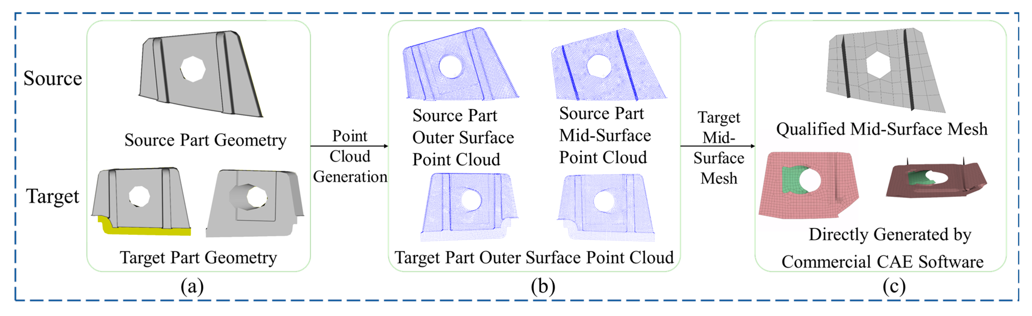
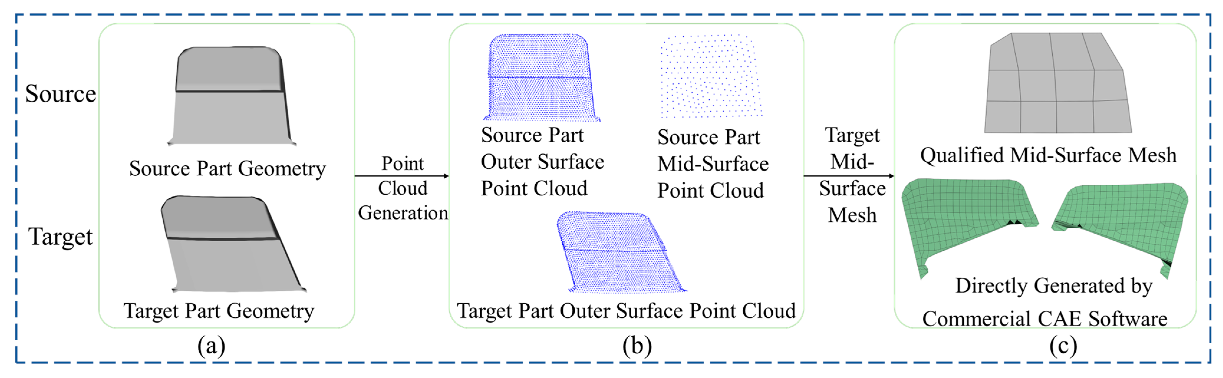
Data Preparation: The source parts possess high-quality standard mid-surface meshes generated by commercial CAE software and verified manually. The corresponding geometric solid models and mid-surface meshes are shown in Figure 3a,c and Figure 4a,c. The derived outer-surface point clouds (Figure 3b and Figure 4b) exhibit uniform density and no significant noise. The normal distance between the mid-surface point cloud and the outer surface is strictly equal to half the design wall thickness, establishing a precise geometric relationship that serves as the baseline template. The target parts provide only the 3D solid models and the derived outer-surface point clouds, designed to verify the method’s capability to handle “globally similar but locally variable” geometries.
(2)
Comparative Baseline: The mid-surface generation module built into mainstream commercial CAE software (ANSYS Design Modeler) was selected as the comparative baseline. As shown in Figure 3c and Figure 4c, the target mid-surface meshes directly generated by this software exhibit significant defects: the former shows obvious geometric deviation in the complex snap-fit region (highlighted in green), while the latter suffers from large-scale mesh loss and detachment from the mid-surface. Both cases require further manual repair.
(3)
Evaluation Metrics: The design is evaluated based on geometric accuracy, processing efficiency, and result quality. First, using the manually repaired mid-surface mesh as the “gold standard,” the normal projection distance between the point cloud generated by the proposed method and the benchmark point cloud is calculated to assess the maximum error and distribution. Second, the total time consumption—from the input of the target outer-surface point cloud to the output of the final mid-surface mesh—is recorded and compared with the average time required by a skilled engineer to complete the “mid-surface extraction–manual repair” workflow using the commercial software. Finally, the topological integrity, feature fidelity, and surface smoothness of the generated meshes are compared qualitatively and quantitatively.

4.2. Analysis of Registration Process and Intermediate Results

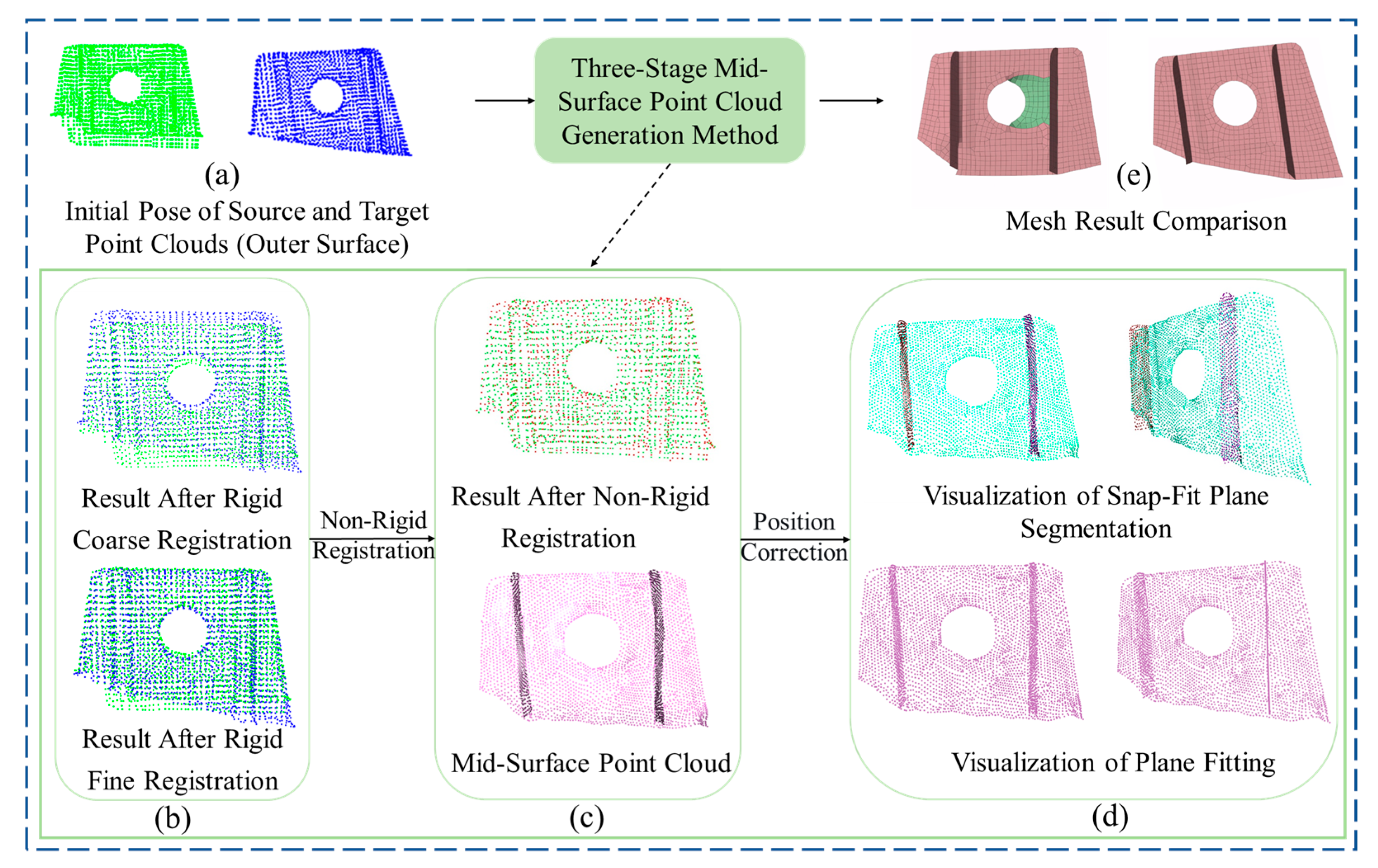
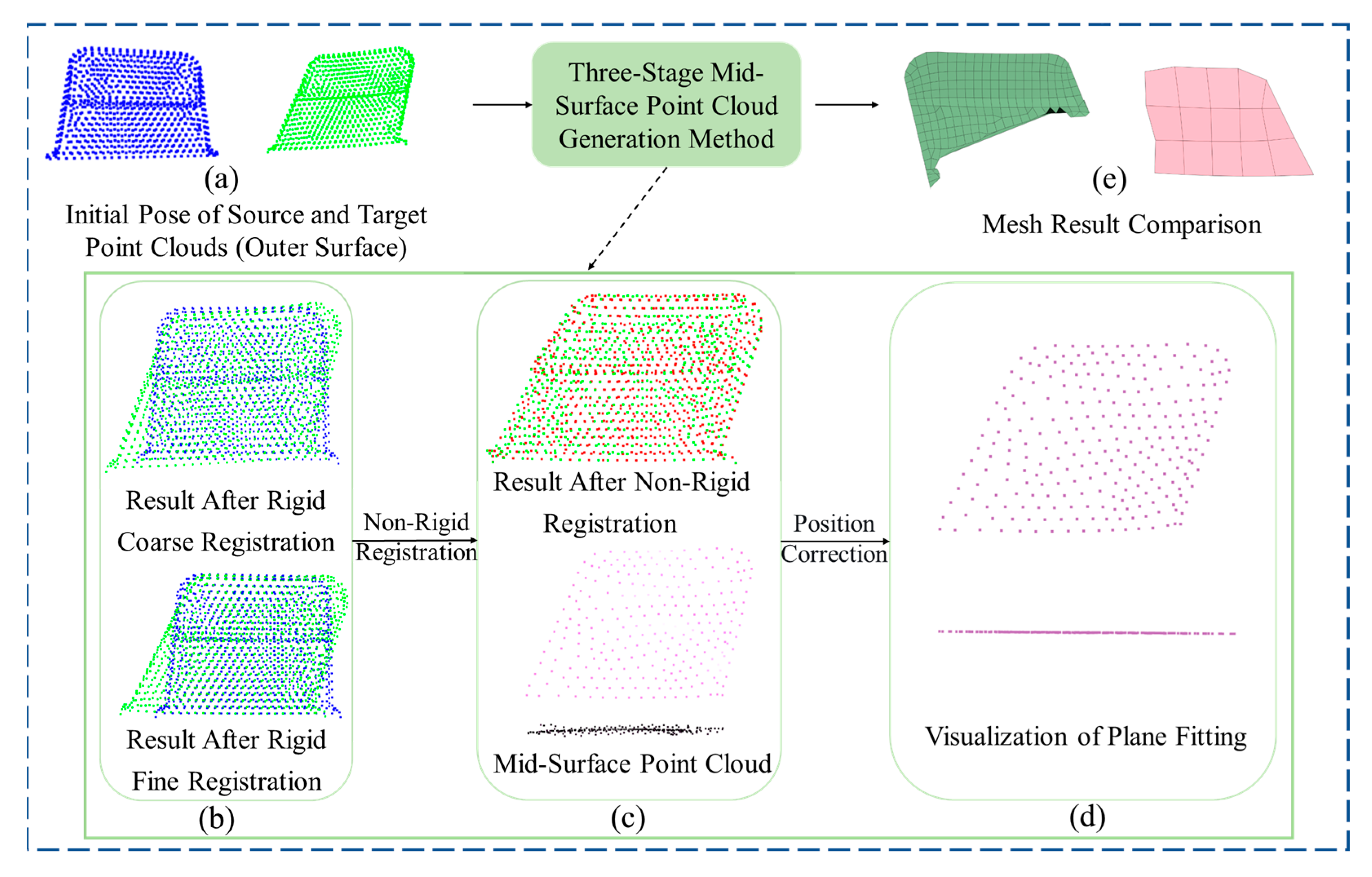
The mid-surface reconstruction process begins with the precise alignment of the outer-surface point clouds of the source and target parts. Figure 5a and Figure 6a illustrate the initial spatial poses of the two, which exhibit significant global offsets. The registration process first employs the RANSAC algorithm for coarse registration. As shown in Figure 5b and Figure 6b, the point cloud poses are preliminarily aligned, but substantial spatial gaps remain (blue indicates source outer surface; green indicates target outer surface). The accuracy at this stage does not yet meet the geometric alignment requirements for subsequent displacement field migration. Subsequently, ICP fine registration is performed to further refine the alignment. By iteratively optimizing the correspondence between the source and target point clouds to minimize the global registration error, a highly overlapped pose alignment is achieved upon completion. Since rigid registration cannot eliminate inherent shape differences between the parts, CPD non-rigid deformation is applied to the rigid registration result of the source point cloud to further compensate for local geometric discrepancies and enhance accuracy. As shown in Figure 5c and Figure 6c, the deformed source outer-surface point cloud (red) achieves a high-precision fit with the target point cloud (green) in both global contours and local details, yielding a high-quality displacement field Vsur.

4.3. Mid-Surface Correction and Final Results

The displacement field Vsur is transferred to the source mid-surface point cloud via the K-NN displacement binding mechanism described in Section 2.4, generating the initial mid-surface point cloud for the target part. At this stage, while the point cloud possesses the target contour, it exhibits obvious local normal jitter, and its accuracy and integrity do not yet meet the standards for direct application. Therefore, a flattening treatment is required.
To address the jitter in the initial mid-surface point cloud, the “Region Growing Segmentation—RANSAC Plane Fitting” combined correction framework proposed in Section 3 is applied. The region growing algorithm clusters and segments the point cloud based on normal vector consistency. The results, shown in Figure 5d and Figure 6d, display different point cloud clusters representing distinct planar regions, with the snap-fit structure clearly separated (the latter case contains only a single plane, thus requiring no segmentation). For each segmented planar cluster, the RANSAC algorithm performs robust plane fitting, and all points are projected onto the fitted plane. This effectively eliminates local normal jitter, resulting in a smooth and flat mid-surface point cloud.
Finally, the corrected point cloud is imported into the CAE software to generate the mid-surface mesh. The side-by-side comparison in Figure 5e and Figure 6e show the mesh cross-sections from the commercial software’s direct output versus the proposed method. Evidently, the mesh generated by the proposed method exhibits no geometric deviation in the snap-fit region and demonstrates superior planarity.

4.4. Comprehensive Performance Evaluation and Discussion

A quantitative analysis of accuracy and efficiency was conducted by comparing the mid-surface mesh generated by the proposed method with the high-quality standard mid-surface mesh (manually generated and verified). The thickness offset rate was used as a metric for accuracy, with results presented in Table 4. Measurements indicate that the maximum normal projection error between the final generated mid-surface point cloud and the “gold standard” benchmark is within 0.05 mm, fully satisfying the geometric model accuracy requirements for engineering CAE analysis (typically on the order of 0.1 mm). Additionally, the total time for the fully automated process is approximately 38 s per part. In contrast, an engineer using commercial software requires an average of approximately 161 s to complete mid-surface extraction and manual repair for snap-fit parts of similar complexity. The proposed method improves processing efficiency by over 73% while ensuring accuracy.
It should be noted that the two cases presented here as exemplary validation studies, which are designed to account for the diverse characteristics of automotive plastic fasteners and the different application scenarios. They verify the effectiveness of the proposed framework in dealing with high-complexity features, while demonstrating the workflow and key advantages of the approach.
In future work, the framework will be extended to a broader range of geometric categories (e.g., large interior panels, complex brackets), and a larger and more diverse dataset will be employed to strengthen statistical validation and significance.
The “Point Cloud Registration—Displacement Binding” pathway proposed in this paper bypasses the step of direct complex mid-surface geometric reasoning and extraction on the target part. Instead, it utilizes deformation migration from a known template, fundamentally avoiding the topological errors and geometric distortions common in traditional feature recognition and Boolean operations. Furthermore, by leveraging the capability of non-rigid registration (CPD) to model local deformations combined with a distance-weighted displacement binding strategy, the method maintains the geometric morphology of fine features such as snap-fits and thin ribs exceptionally well—a feat difficult to achieve with traditional geometric simplification methods. The entire workflow requires no manual parameter intervention; it achieves high automation through voxel IoU-based automatic template matching and Chamfer distance-based adaptive registration parameter adjustment, thereby reducing reliance on operator experience and improving result consistency and reproducibility.
Despite the excellent performance on the typical snap-fit parts described above, the method has certain limitations. First is the dependency on the source library; reconstruction quality depends to some extent on the topological similarity between the source (template) and the target. If the target part presents a completely new topology lacking a corresponding template in the database, registration accuracy will be compromised. Second is the computational cost; the complexity of CPD non-rigid registration is high when processing large-scale dense point clouds, limiting its direct application to ultra-large full-vehicle models. Additionally, the current experiments focus on specific types of plastic snap-fits; the generalizability of the method requires further validation on a broader variety of automotive plastic parts.
Future research will focus on the following directions. First, the standardized source point cloud library will be expanded to cover a wider variety of complex interior panels and structural components, thereby broadening the method’s applicability. Second, further validation is needed on a broader range of automotive plastic parts—such as large interior panels and structural components with complex reinforcement ribs—to better assess the robustness and generalizability of the method, particularly when applied to real scanned data. Third, exploring the deep integration of deep learning techniques (e.g., PointNet++) into the registration process to replace traditional iterative optimization algorithms, further enhancing the intelligence and generalization capability of the reconstruction process. And forth, optimizing algorithm efficiency to support the rapid generation of mid-surfaces for large-scale full-vehicle assemblies.

5. Conclusions

To address persistent industry challenges in CAE preprocessing of automotive plastic parts, notably low accuracy in mid-surface extraction, inadequate automation, and high labor costs stemming from complex geometries, this paper proposes an automated mid-surface mesh reconstruction method based on point cloud registration. An integrated technical framework of “Multimodal Registration—Displacement Binding—Surface Correction” is established, enabling fully automated, high-precision generation of mid-surface meshes directly from target outer-surface point clouds. Based on theoretical derivation and comparative experiments using representative components, the following principal conclusions are drawn:
(1)
A multimodal registration strategy that combines RANSAC-ICP rigid registration with CPD non-rigid registration is proposed. This approach effectively addresses point-cloud alignment challenges induced by local deformations and manufacturing tolerances, providing a precise foundation for displacement-field computation. Furthermore, an innovative displacement-binding mechanism based on K-NN search is designed, which establishes a robust geometric correlation between the outer surface and the mid-surface. This mechanism achieves high-fidelity transfer of deformation information without the need for direct mid-surface registration. Finally, an adaptive surface-correction algorithm integrating region growing and RANSAC plane fitting is developed, effectively eliminating point-cloud noise and local distortions to ensure geometric integrity and smoothness of the final mid-surface mesh.
(2)
An adaptive parameter-tuning mechanism based on Voxel IoU and Chamfer Distance is introduced, allowing the algorithm to automatically adjust registration parameters according to the geometric discrepancy of the target part, without manual intervention. This design ensures robust performance for plastic parts within the same category that exhibit local design variations, such as changes in hole positions or fine-tuning of reinforcement ribs, thereby realizing the engineering objective of “model once, reuse in batches”.
(3)
Validation on typical automotive plastic snap-fit components demonstrates that the normal projection error between the mid-surface mesh generated by the proposed method and the manually verified reference mesh remains below 0.05 mm. The single-part processing time is only 38 s, representing an efficiency improvement of over 73% compared to the manual workflow in commercial CAE software. The method successfully avoids common drawbacks of traditional approaches, such as mid-surface distortion and feature loss, significantly enhancing both the automation level and geometric precision of CAE preprocessing for complex plastic parts.
In summary, the proposed method reduces the traditional reliance on manual intervention in mid-surface extraction, markedly improving the efficiency and reliability of CAE preprocessing for automotive plastic components. Its compatibility with existing engineering workflows, along with its potential for extension to multi-material and large-scale models, indicates broad application prospects in automotive design and other fields involving thin-walled parts.

Author Contributions

Conceptualization, Y.M.; methodology, Y.M.; software, Y.M.; validation, H.T. and J.D.; formal analysis, J.W.; investigation, S.W.; resources, Z.H.; data curation, Z.Z.; writing—original draft preparation, Y.M.; writing—review and editing, Z.H.; visualization, Z.W.; project administration, Z.H.; funding acquisition, Z.H. All authors have read and agreed to the published version of the manuscript.

Funding

This research was funded by the MAJOR SCIENCE AND TECHNOLOGY SPECIAL PROJECT OF JILIN PROVINCE AND CHANGCHUN CITY, grant number 20240301010ZD.

Data Availability Statement

The data presented in this study are available on request from the corresponding author due to privacy restrictions.

Acknowledgments

The authors would like to thank the editor and the anonymous reviewers for their careful reading and constructive comments, which have greatly improved this work.

Conflicts of Interest

Yan Ma, Hongbin Tang, Zehui Huang, Jianjiao Deng, Jingchun Wang, and Shibin Wang are employee of National Key Laboratory of Advanced Vehicle Integration and Control, FAW Global R&D Center, Changchun 130013, China. Zhiguo Zhang, and Zhenjiang Wu are employee of CATARC (Tianjin) Automotive Engineering Research Institute Co., Ltd., Tianjin 300000, China. The remaining authors declare that the research was conducted in the absence of any commercial or financial relationships that could be construed as a potential conflict of interest.

Abbreviations

The following abbreviations are used in this manuscript:
CAEComputer-Aided Engineering
FEAFinite Element Analysis
NVHNoise, Vibration, and Harshness
CADComputer-Aided Design
APIApplication Programming Interface
MATMedial Axis Transform
CATChordal Axis Transform
RANSACRandom Sample Consensus
ICPIterative Closest Point
CPDCoherent Point Drift
K-NNK-Nearest Neighbor
IoUIntersection over Union
FPFHFast Point Feature Histogram
SVDSingular Value Decomposition
RMSERoot Mean Square Error
CDChamfer Distance
GMMGaussian Mixture Model
EMExpectation-Maximization
RBFRadial Basis Function
BFSBreadth-First Search
L2Euclidean Distance
KD-treeK-Dimensional Tree

References

  1. Gao, J.; Gindy, N.; Chen, X. An automated GD&T inspection system based on non-contact 3D digitization. Int. J. Prod. Res. 2006, 44, 117–134. [Google Scholar]
  2. Wang, F.; Wang, H.; Zhao, X.; Ran, Q.; Wang, G.; Zhang, H.; Hu, X.; Li, S.; Cui, X. Mid-surface mesh abstraction for thin-walled structures based on virtual topology. Comput.-Aided Des. 2025, 183, 103865. [Google Scholar] [CrossRef]
  3. Li, Y.; Gu, P. Inspection of free-form shaped parts. Robot. Comput. Integr. Manuf. 2005, 21, 421–430. [Google Scholar] [CrossRef]
  4. Gentilini, I.; Shimada, K. Predicting and evaluating the post-assembly shape of thin-walled components via 3D laser digitization and FEA simulation of the assembly process. Comput.-Aided Des. 2011, 43, 316–328. [Google Scholar] [CrossRef]
  5. Lu, Q.; Xiao, M.; Lu, Y.; Yuan, X.; Yu, Y. Attention-based dense point cloud reconstruction from a single image. IEEE Access 2019, 7, 137420–137431. [Google Scholar] [CrossRef]
  6. Ma, S.; Tian, L. Analysis feature recognition and mixed-dimensional model reconstruction from finite element analysis mesh model. Proc. Inst. Mech. Eng. Part C J. Mech. Eng. Sci. 2014, 228, 1197–1211. [Google Scholar] [CrossRef]
  7. Yuan, X.; Kong, L.; Feng, D.; Wei, Z. Automatic feature point detection and tracking of human actions in time-of-flight videos. IEEE/CAA J. Autom. Sin. 2017, 4, 677–685. [Google Scholar] [CrossRef]
  8. Radvar-Esfahlan, H.; Tahan, S. Nonrigid geometric metrology using generalized numerical inspection fixtures. Precis. Eng. 2012, 36, 1–9. [Google Scholar] [CrossRef]
  9. Marchand, Y.; Caraffa, L.; Sulzer, R.; Clédat, E.; Vallet, B. Evaluating Surface Mesh Reconstruction Using Real Data. Photogramm. Eng. Remote Sens. 2023, 89, 625–638. [Google Scholar] [CrossRef]
  10. Blum, H. A transformation for extracting new descriptions of shape. In Models for the Perception of Speech and Visual Form; MIT Press: Cambridge, MA, USA, 1967; pp. 362–380. [Google Scholar]
  11. Quadros, W.R.; Shimada, K. Hex-layer: Layered all-hex mesh generation on thin section solids via chordal surface transformation. In Proceedings of the 13th International Meshing Roundtable, Williamsburg, VA, USA, 19–22 September 2004; pp. 169–180. [Google Scholar]
  12. Lee, H.; Nam, Y.; Park, S. Graph-based midsurface extraction for finite element analysis. In Proceedings of the 2007 11th International Conference on Computer Supported Cooperative Work in Design, Melbourne, Australia, 26–28 April 2007; pp. 1055–1058. [Google Scholar]
  13. Chong, C.; Senthil Kumar, A.; Lee, K. Automatic solid decomposition and reduction for non-manifold geometric model generation. Comput.-Aided Des. 2004, 36, 1357–1369. [Google Scholar] [CrossRef]
  14. Woo, Y. Abstraction of mid-surfaces from solid models of thin-walled parts: A divide-and-conquer approach. Comput.-Aided Des. 2014, 47, 1–11. [Google Scholar] [CrossRef]
  15. Mounir, H.; Nizar, A.; Abdelmajid, B. CAD model simplification using a removing details and merging faces technique for a FEM simulation. J. Mech. Sci. Technol. 2012, 26, 3539–3548. [Google Scholar] [CrossRef]
  16. Sheen, D.; Son, T.; Myung, D.; Ryu, C.; Lee, S.; Lee, K. Transformation of a thin-walled solid model into a surface model via solid deflation. Comput.-Aided Des. 2010, 42, 720–730. [Google Scholar] [CrossRef]
  17. Qin, Z.; Yu, H.; Wang, C.; Peng, Y.; Xu, K. Deep graph-based spatial consistency for robust non-rigid point cloud registration. In Proceedings of the IEEE/CVF Conference on Computer Vision and Pattern Recognition (CVPR), Vancouver, BC, Canada, 18–22 June 2023; pp. 5394–5403. [Google Scholar]
  18. Jiang, P.; Sun, M.; Huang, R. Neural intrinsic embedding for non-rigid point cloud matching. In Proceedings of the IEEE/CVF Conference on Computer Vision and Pattern Recognition (CVPR), Vancouver, BC, Canada, 18–22 June 2023; pp. 1–10. [Google Scholar]
  19. Kovács, I.; Varady, T. Constrained fitting with free-form curves and surfaces. Comput.-Aided Des. 2020, 122, 102816. [Google Scholar] [CrossRef]
  20. Zhang, H.; Li, C.; Gao, L.; Li, S.; Wang, G. Shape segmentation by hierarchical splat clustering. Comput. Graph. 2015, 51, 136–148. [Google Scholar] [CrossRef]
  21. Li, Y.; Harada, T. Non-rigid point cloud registration with neural deformation pyramid. Adv. Neural Inf. Process. Syst. 2022, 35, 27757–27768. [Google Scholar]
  22. Myronenko, A.; Song, X. Point set registration: Coherent point drift. IEEE Trans. Pattern Anal. Mach. Intell. 2010, 32, 2262–2275. [Google Scholar] [CrossRef]
  23. Qi, C.; Su, H.; Mo, K.; Guibas, L. Pointnet: Deep learning on point sets for 3d classification and segmentation. In Proceedings of the IEEE Conference on Computer Vision and Pattern Recognition (CVPR), Honolulu, HI, USA, 21–26 July 2017; pp. 652–660. [Google Scholar]
  24. Huang, X.; Zhang, J.; Fan, L.; Wu, Q.; Yuan, C. A systematic approach for cross-source point cloud registration by preserving macro and micro structures. IEEE Trans. Image Process. 2017, 26, 3261–3276. [Google Scholar] [CrossRef]
  25. Zhao, F.; Huang, H.; Hu, W. An optimized hierarchical point cloud registration algorithm. Multimed. Syst. 2025, 31, 14. [Google Scholar] [CrossRef]
  26. Monji-Azad, S.; Kinz, M.; Kothari, S.; Khanna, R.; Mihan, A.; Männel, D.; Scherl, C.; Hesser, J. DefTransNet: A transformer-based method for non-rigid point cloud registration in the simulation of soft tissue deformation. Meas. Sci. Technol. 2025, 38, 076006. [Google Scholar] [CrossRef]
  27. Monji-Azad, S.; Hesser, J.; Low, N. A review of non-rigid transformations and learning-based 3D point cloud registration methods. ISPRS J. Photogramm. Remote Sens. 2023, 196, 58–72. [Google Scholar] [CrossRef]
  28. Huang, J.; Birdal, T.; Gojcic, Z.; Guibas, L.; Hu, S. Multiway non-rigid point cloud registration via learned functional map synchronization. IEEE Trans. Pattern Anal. Mach. Intell. 2022, 44, 8983–9000. [Google Scholar] [CrossRef] [PubMed]
  29. Deng, B.; Yao, Y.; Dyke, R.; Zhang, J. A survey of non-rigid 3D registration. Comput. Graph. Forum 2022, 41, 559–589. [Google Scholar] [CrossRef]
  30. Li, Y.; Liu, Y.; Dong, Z.; Jiang, L.; Lin, Y. Unsupervised Non-Rigid Human Point Cloud Registration Based on Deformation Field Fusion. IEEE Trans. Vis. Comput. Graph. 2025, 31, 7566–7588. [Google Scholar] [CrossRef] [PubMed]
  31. Zhou, Z.; Sun, Z.; Luo, P. Adaptive Robotic Deburring of Molded Parts via 3D Vision and Tolerance-Constrained Non-Rigid Registration. J. Manuf. Mater. Process. 2025, 9, 294. [Google Scholar] [CrossRef]
  32. Chen, B.; Zhou, Z.; Liu, L.; Yu, L.; Li, X. A two-stage point elimination with salient fusion features for point cloud registration. Eng. Appl. Artif. Intell. 2025, 162, 112563. [Google Scholar] [CrossRef]
  33. Deng, H.; Birdal, T.; Ilic, S. Ppfnet: Global context aware local features for robust 3d point matching. In Proceedings of the IEEE Conference on Computer Vision and Pattern Recognition (CVPR), Salt Lake City, UT, USA, 18–23 June 2018; pp. 195–205. [Google Scholar]
  34. Gojcic, Z.; Zhou, C.; Wegner, J.; Wieser, A. The perfect match: 3D point cloud matching with smoothed densities. In Proceedings of the IEEE/CVF Conference on Computer Vision and Pattern Recognition (CVPR), Long Beach, CA, USA, 15–20 June 2019; pp. 5545–5554. [Google Scholar]
  35. Liu, X.; Qi, C.; Guibas, L. Flownet3d: Learning scene flow in 3d point clouds. In Proceedings of the IEEE/CVF Conference on Computer Vision and Pattern Recognition (CVPR), Long Beach, CA, USA, 15–20 June 2019; pp. 529–537. [Google Scholar]
  36. Wang, Y.; Solomon, J. Prnet: Self-supervised learning for partial-to-partial registration. Adv. Neural Inf. Process. Syst. 2019, 32, 8812–8824. [Google Scholar]
  37. Hu, X.; Zhang, D.; Chen, J.; Wu, Y.; Chen, Y. Nrtnet: An unsupervised method for 3d non-rigid point cloud registration based on transformer. Sensors 2022, 22, 5128. [Google Scholar] [CrossRef]
  38. Gustavo Marques, N.; Oliveira, M. Robust point-cloud registration based on dense point matching and probabilistic modeling. Vis. Comput. 2022, 38, 3217–3230. [Google Scholar] [CrossRef]
  39. Ouyang, B.; Raviv, D. Occlusion guided scene flow estimation on 3D point clouds. In Proceedings of the 2021 IEEE/CVF Conference on Computer Vision and Pattern Recognition Workshops (CVPRW), Nashville, TN, USA, 19–25 June 2021; pp. 2799–2808. [Google Scholar]
  40. Monji-Azad, S.; Kinz, M.; Hesser, J. Robust-defreg: A robust deformable point cloud registration method based on graph convolutional neural networks. arXiv 2023, arXiv:2306.04701. [Google Scholar]
Figure 1. Distribution and geometric features of typical automotive plastic components.
Vehicles 08 00089 g001
Figure 2. Flowchart of the automated mid-surface mesh generation method.
Vehicles 08 00089 g002
Figure 3. Data preparation and baseline comparison for Case 1: (a) Geometric models of the source and target parts; (b) Generated point cloud data for outer surfaces and mid-surfaces; (c) Comparison between the qualified source mid-surface mesh and the target mid-surface mesh directly generated by commercial CAE software.
Vehicles 08 00089 g003
Figure 4. Data preparation and baseline comparison for Case 2: (a) Geometric models of the source and target parts; (b) Generated point cloud data for outer surfaces and mid-surfaces; (c) Comparison between the qualified source mid-surface mesh and the target mid-surface mesh directly generated by commercial CAE software.
Vehicles 08 00089 g004
Figure 5. Analysis of the registration process and intermediate results for Case 1: (a) Initial spatial pose of source and target outer-surface point clouds; (b) Results of rigid registration stages; (c) Outcomes of non-rigid registration showing the aligned outer surfaces and the migrated mid-surface point cloud; (d) Visualization of the position correction process including plane segmentation and fitting; (e) Comparison of final mesh quality between commercial software (left) and the proposed method (right).
Vehicles 08 00089 g005
Figure 6. Analysis of the registration process and intermediate results for Case 2: (a) Initial spatial pose of source and target outer-surface point clouds; (b) Results of rigid registration stages; (c) Outcomes of non-rigid registration showing the aligned outer surfaces and the migrated mid-surface point cloud; (d) Visualization of the position correction process including plane segmentation and fitting; (e) Comparison of final mesh quality between commercial software (left) and the proposed method (right).
Vehicles 08 00089 g006
Table 1. Comparison of performance results under different IoU thresholds.
IoU ThresholdsRecognition AccuracyAverage Time
0.8584.3%1.1 h
0.992.3%1.2 h
0.9396.7%1.5 h
0.9599.2%2.0 h
0.9899.8%2.6 h
Table 2. Performance comparison of neighbor search under different K-NN values.
K ValuesRecognition AccuracyAverage Time
1072%0.06 s
2078%0.09 s
3092%0.11 s
4094%0.16 s
5095%0.21 s
Table 3. Performance comparison of neighbor search under different KD-tree values.
KD-tree ValuesMesh Matching AccuracySingle Search Time
575%0.03 s
1078%0.04 s
2092%0.06 s
3093%0.09 s
4095%0.13 s
Table 4. Comprehensive Performance Evaluation.
Input ModelCase 1Case 2
Commercial CAE Time180 s161 s
Commercial CAE Thickness Offset Rate28%23%
Proposed Method Time41 s38 s
Proposed Method Thickness Offset Rate7%5%
Normal Projection Error 0.04 mm0.03 mm
Disclaimer/Publisher’s Note: The statements, opinions and data contained in all publications are solely those of the individual author(s) and contributor(s) and not of MDPI and/or the editor(s). MDPI and/or the editor(s) disclaim responsibility for any injury to people or property resulting from any ideas, methods, instructions or products referred to in the content.