Abstract
The accurate prediction of tire and brake thermomechanical behavior is crucial for various applications in the automotive industry, including vehicle dynamics analysis, racing performance optimization, and driver assistance system development. The temperature of the brakes plays a crucial role in determining the performance of rubber by altering its temperature. This change impacts the rim and the air within the tire, leading to variations in temperature and tire pressure, which consequently affect the vehicle’s overall performance. Traditionally, these components have been modeled separately, neglecting the crucial thermal interaction between them, thereby losing a lot of important information from the outside that influences the tire. This paper presents a novel method that overcomes this limitation by coupling the thermomechanical models of the tire and brake, enabling a more comprehensive understanding of their combined behavior. Therefore, the present work could be an interesting starting point to understand how a control system can be influenced by the thermodynamic of the wheel–brake system.
1. Introduction
Within the automotive industry, particularly in the fiercely competitive world of racing, the knowledge of the correct operating window of a tire is essential to achieve maximum grip, performance, and safety [1,2,3,4]. Furthermore, along with the suspension system, it assumes a main role in the vibrational field [5,6,7,8,9]. An accurate analysis of the tire can be performed through multi-physics analysis or via CFD simulations [10,11,12], and the fundamental characteristics to be included in the model can be obtained through various types of non-destructive tests, including in the world of motorsport [13,14,15,16,17,18]. Furthermore, cutting-edge numerical methodologies have paved the way for precise estimations, enabling real-time applications in vehicle design and performance optimization [19,20,21,22,23]. The temperature range in which tires operate is impacted by various elements, such as road conduction, internal air circulation, external air movement, and frictional forces [24,25,26]. The heat produced from the friction between the pads and brake disc generates a significant amount of heat, and the portion of this heat that is not dissipated into the surroundings influences the temperature of the tire’s rim, consequently warming the wheel’s internal air. This affects the pressure and subsequently alters the thermal gradient of tire’s inner layer, which directly interacts with the tire internal air [27,28]. This portion of heat therefore cannot be neglected and must be made so that it becomes an input of the thermal model concerning the tire [29,30]. Most of the literature reviews study the brake and the tire thermal model separately. Guner et al. [31] developed a dynamic model of braking system; they conducted thermal analysis on both disk and drum brakes. A great number of authors have focused their studies on the modeling of the brake disk since it is the most critical component of brake system. Bakar et al. [32] developed an FEM model of the brake disk considering its wear and how it affects its performance and the thermal distribution between disk and pads. Concerning the tire thermal model, Clabrese et al. [33] presented an interesting thermal model based on the diffusion law of Fourier coupled with a structural MBD tire model and the MF formulation. The authors highlighted the importance of considering the thermal behavior of the tire to improve the vehicle safety and performance. The interest in the thermal behavior of tires to ensure safety is not limited to passenger or sports vehicles but also to truck vehicles [34]; the paper shows that monitoring the temperature of the side of the tires by thermal infrared images is an innovative and effective method to evaluate in real time the load of trucks’ overload. This paper offers a more comprehensive and accurate representation of the thermomechanical interaction between the tire and brake, paving the way for improving vehicle dynamics analysis, performance optimization, and safety-critical applications. An example of how performance and safety could be improved, by considering the influence of the brake thermodynamics, could be found in a different behavior of the control safety systems such as ABS and ECS [35,36]. The developed models incorporate various factors such as material properties, geometric configurations, and operational conditions to predict the thermomechanical behavior accurately. The simulation results are then validated through experimental tests using instrumented race vehicles equipped with infrared (IR) sensors and thermocouples to measure temperature. The experimental setup also includes the use of Tire Pressure Monitoring Systems (TPMSs) to capture the internal air pressure, providing a comprehensive dataset for validation.
2. Tire and Brake Simulation Platform
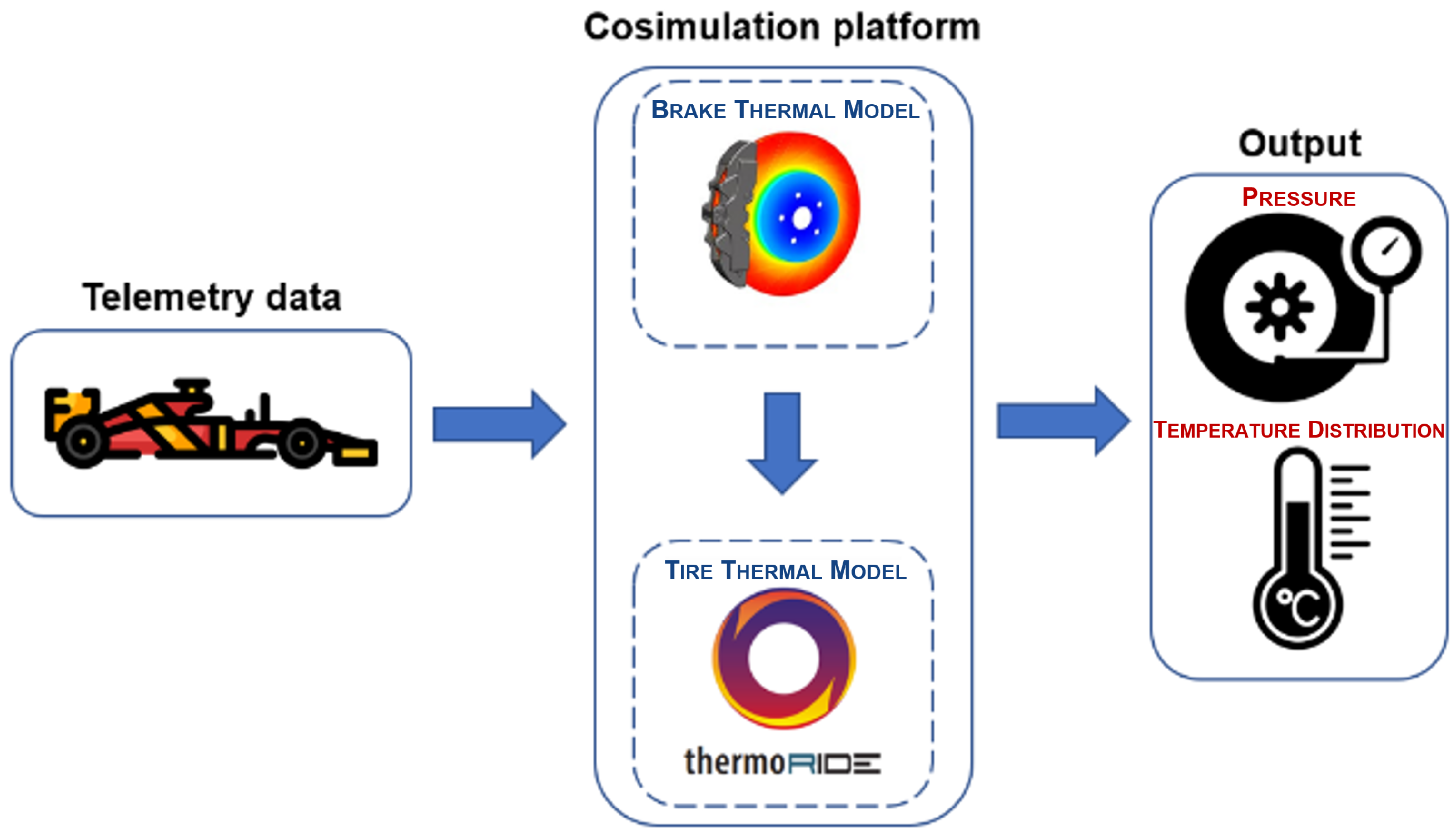
Two models are integrated on this platform: the brakes thermal model and the tire thermal model. Starting from the left side of the diagram in Figure 1, the input channels of various sensors placed on the car are shown, which are useful to obtain information that directs the subsequent phases of the analysis and are also important to have information about brakes. The information extracted from the vehicle’s sensor during the initial estimation serves as input to the tire model, which is a fundamental part of the integrated platform. At this point, the thermal brake and the tire model work together, then output the tire pressure and temperature distribution.
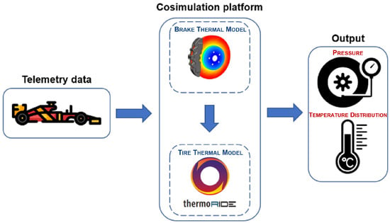
Figure 1.
Integrated platform between the tire and brake thermal model.
2.1. Brake Thermal Model
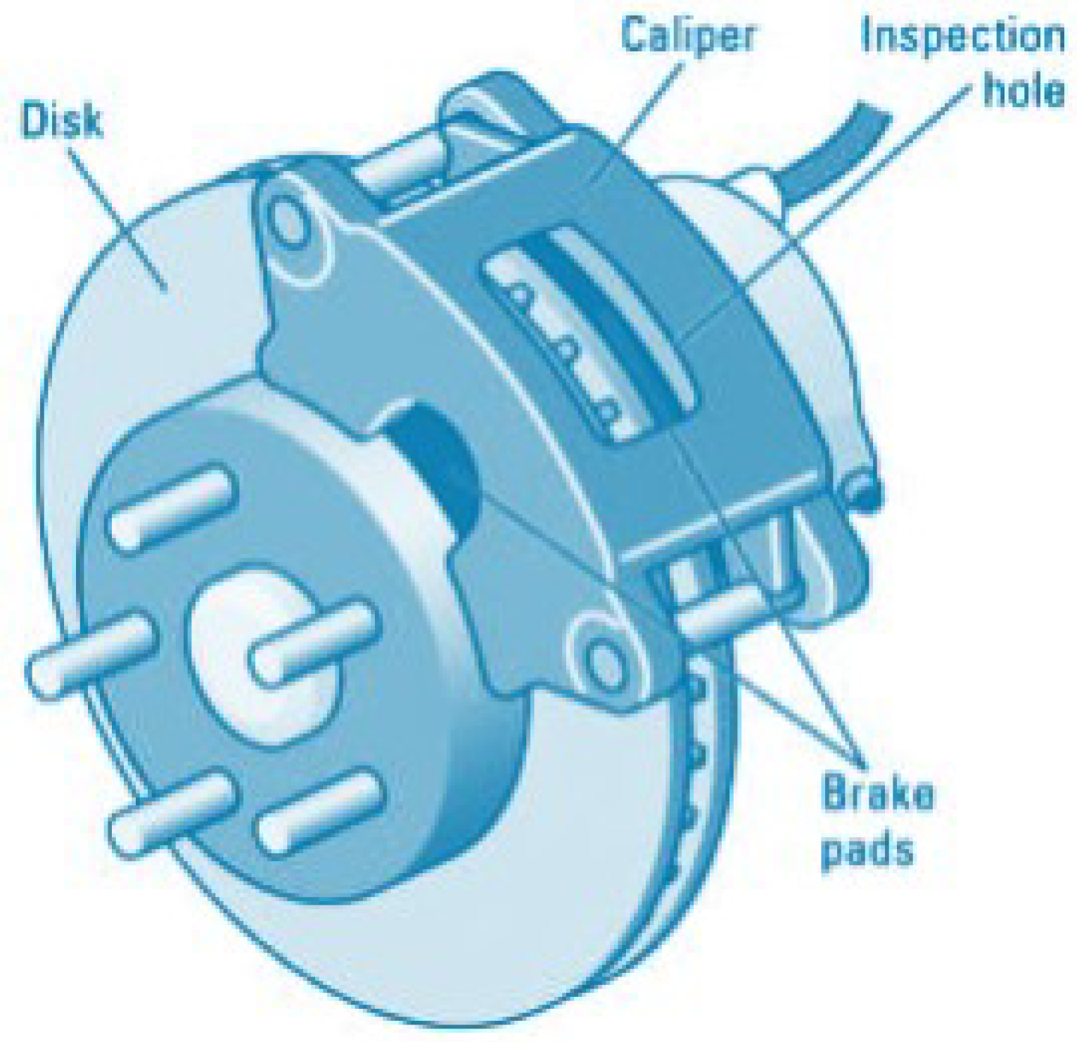
The effectiveness of disc brakes, a critical safety component in vehicles, is influenced by a multitude of factors, including the design, material characteristics, and operating conditions [37,38]. A scheme of the brake system is shown in Figure 2. The developed brake thermal model considers four factors that impact temperature, like the heat generation through friction, the brake’s convection heating or cooling with the surrounding air, the radiation emitted from the wheel affecting the brake temperature, and the heat transfer through conduction between the brake and the wheel.
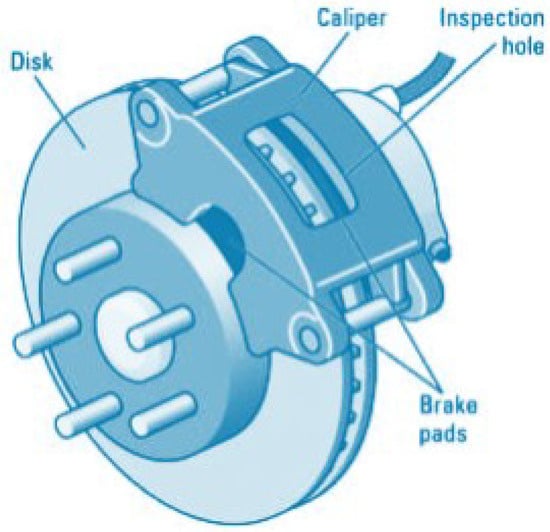
Figure 2.
Brake system.
To model the heat exchanges mentioned, it is essential to identify precise analytical expressions for these heat exchange processes. This enables a detailed description of thermal behavior associated with the brake system.
Regarding the brake friction power, it can be evaluated as follows:
where
- is the brake friction power;
- is the brake torque measured by sensor defined in Section 3;
- is the wheel speed.
The brake torque , in turn, can be computed as
Equation (2) includes the following variables in order to evaluate the brake torque: representing the brake pressure measured with the sensor, denoting the coefficient of friction of the brakes, indicating the sum of the piston area of both the inboard and outboard sides of a single front caliper, and , which is the effective radius of the brake discs. The brake friction power, shown in Equation (1), is distributed between the brake disc and the pad through the following heat partition coefficient:
In this equation, and are the contact surface area of the disc and of the pad, respectively, while represents the thermal effusivity:
where k is the thermal conductivity, and is the thermal capacity. Then, it is possible to obtain the disc temperature increase:
The heat input is generated by the brake torque :
The heat output is represented by the amount of heat lost through convection with the surrounding air and it can be computed as follows [39]:
where represents the convective heat transfer power, denotes the convective coefficient, is the area of the disc brakes, encompassing both the frictional and side surfaces of the disc, is the air temperature, and is the brake disc temperature [40,41,42]. The rate of heat transfer is expressed as follows:
where is the Boltzmann constant, and represents the wheel temperature. The conductive heat transfer power of the brake can be assessed by considering the thermal conductivity between the wheel and the brake, , as presented in Equation (9):
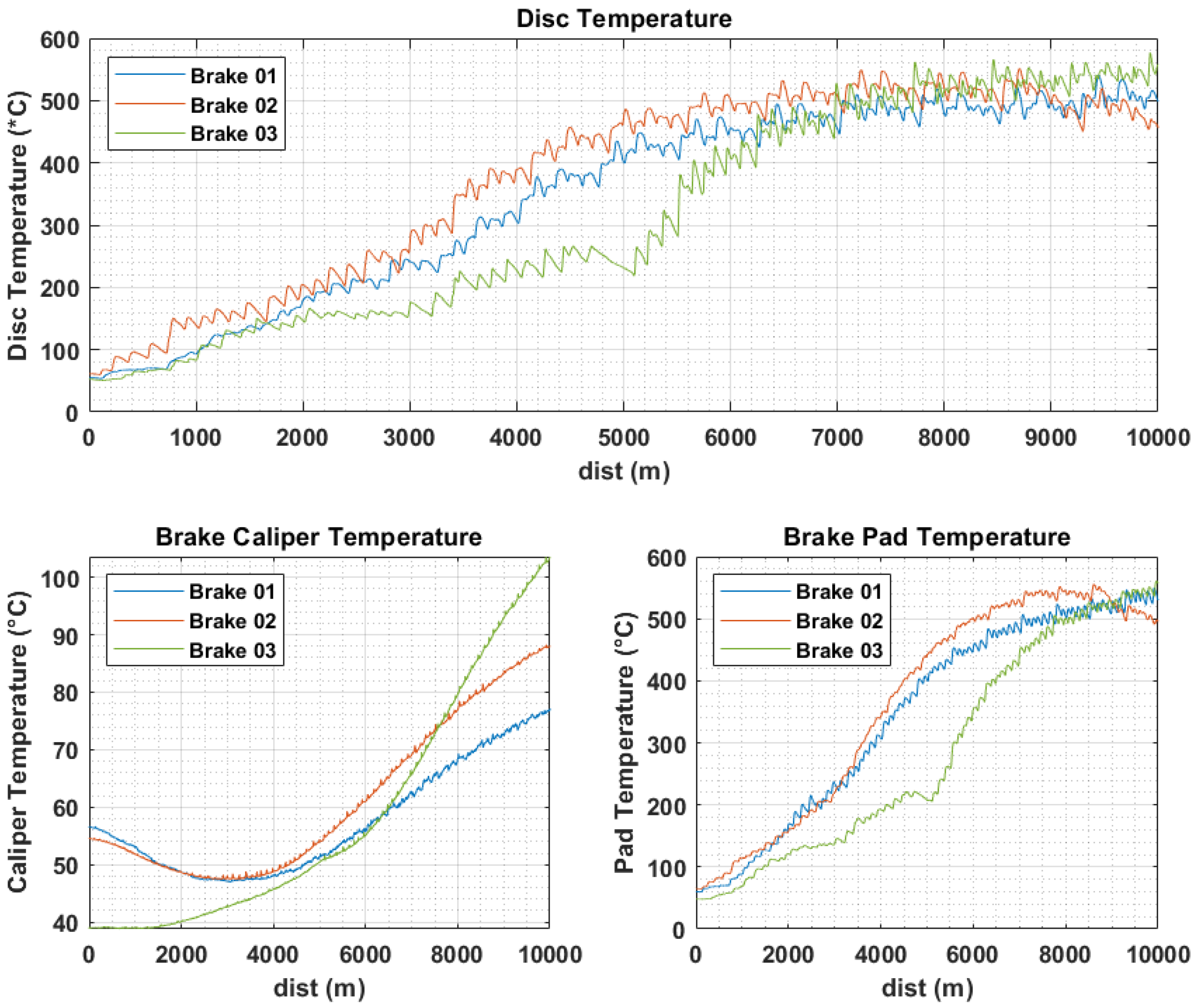
However, the formulas provided include coefficients and values that vary based on the brake type, materials used, and geometries of the brake components, and to address this, a series of tests were conducted in collaboration with our partners on diverse brake systems. These systems encompass different types of calipers (both fixed and floating), as well as vented and non-vented discs. In Figure 3, the temperatures of the disc, brake pad, and caliper for three different brake system types can be seen.
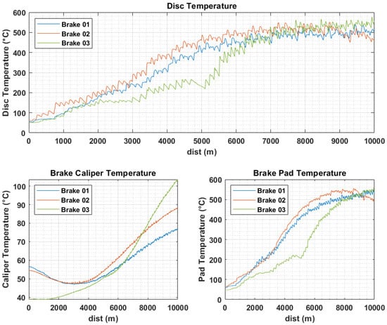
Figure 3.
Acquired temperatures of the disc, brake pad, and brake caliper.
The test scenarios encompass a range of factors, including vehicle velocities, rotor configurations, brake pad compositions, and external conditions [43,44]. These tests unveiled different temperature profiles and gradient changes, especially after alterations to the brake material. These results provide valuable insights for improving the model’s adaptability and usefulness.
2.2. Tire Thermal Model
An important requirement to ensure traction in various driving conditions requires that the vehicle’s tires operate at an ideal temperature so that the tire–road interaction force is achieved as best as possible in this way. However, the accurate measurement and control of the tire core temperature is a significant challenge, and thermoRIDE, a physical analytical model, can be used to solve this particular problem. This model enables the evaluation of tire pressure trends and provides insight into some mechanisms which affect the tire thermal evolution. thermoRIDE studies the physical mechanisms of heat exchange and heat production, such as heat generation in the tire structure from the tangential interaction between the tire and the road, heat exchange with the external environment from the thermal conductivity between the tire tread and the road, and surface and thermal conductivity between the tire layers due to temperature gradient. When inspecting a tire, the existence of its curvature and the shoulder and sidewall has to be taken into account during this type of study. The lateral nodes are divided in ribs, typically three cars and up to fifteen motorcycles. The model is fed from telemetry data, which are defined in Table 1:

Table 1.
ThermoRIDE model inputs.
The model provides us with thermal data in the output, which are then compared with the acquired temperature data. Concerning the mathematical tire model, it is based on the use of the diffusion law of Fourier applied to a three-dimensional domain:
3. Experimental Tests
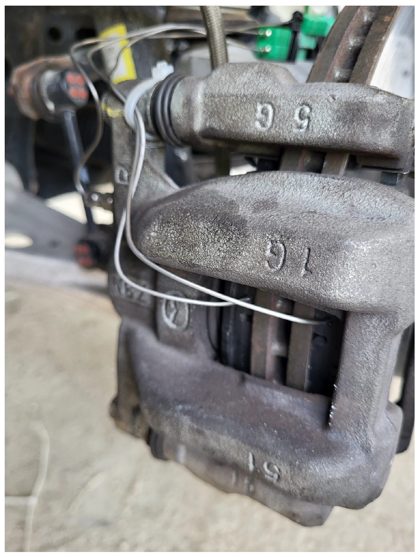
The experimental tests were conducted with the aim to calibrate the brake systems correctly in the thermal model and the heat transfer between brakes and tires. This method was selected to guarantee that the calibration aligns the internal surfaces and internal air temperatures of the proposed models with the actual temperatures measured by the sensors throughout all stages of operation. The main goal was to achieve a good level of agreement between our modeled predictions and the experimental data collected by the sensors used to acquire the brake temperature and set it in the brake system as can be seen in Figure 4.
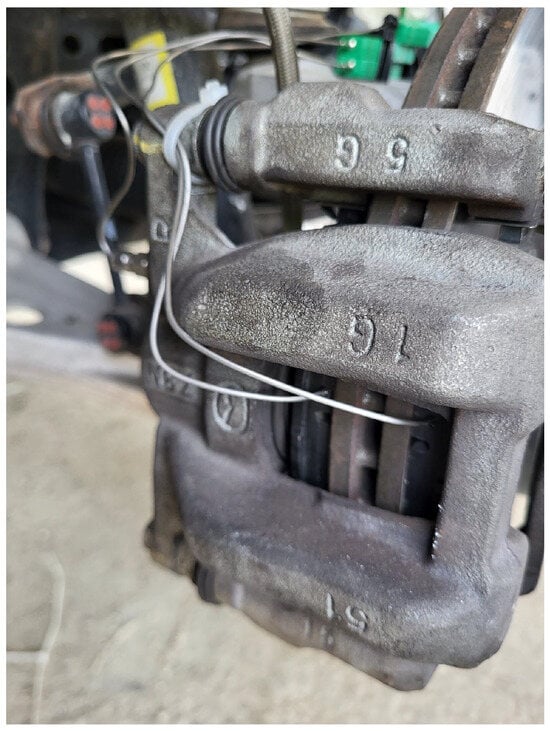
Figure 4.
Thermocouples installed to acquire temperatures of disc and brake pad.
The original brake discs were substituted by the ones provided by the partner using the same assembly procedure for each of them. For example, a torque wrench was used to ensure the same tightening torque. Therefore, the same tire was used for each test, starting from the same initial condition in terms of temperature and pressure. The value of the ambient temperature was about 25 °C for each test. The test protocol defined the first four laps of each run as warm-up laps to raise the tires to the operating temperature, followed by 13 push laps to raise the tires to the maximum temperature and then pass the initial transient, which differed from previous tests in [28] to calibrate the model with blanking.
Tire and Vehicle Models Parameterization
The main goal of parameterizing models is to accurately replicate experimental data, trying to minimize the gap between simulation results and sensor measurements. For the current test session, the following sensors are employed. These sensors allow to obtain the parameters that are used for the thermal model of wheel and brake, for example vSlidingSpeed and the Fx, Fy and Fz forces on the wheel:
- S-Motion: A Correvit S-Motion Type 2055 A sensor is used for the measurement of longitudinal and lateral velocity, sideslip angle, and run distance. It has a range of 400 km/h, a linear velocity measurement accuracy < and an angle resolution <0.01°. The acquisition frequency is 100 Hz.
- IMU: The OXTS 3000 is an inertial platform which measures pitch, roll and yaw rate. It presents the following specifications: accelerometer, bias stability 2 μg, Servo technology, range 10 g, gyroscope, bias stability 2°/h, MEMS technology, and range 100°/s.
- Encoders: The Bosch HA-M is used to measure the wheel angular speed. It has a max frequency of 4.2 kHz and an accuracy repeatability of the falling edge of tooth <4%.
- An infrared sensor is used to measure the tread surface temperature. The acquisition frequency is 10 Hz.
- Internal powered pressure and IR temperature array sensor pressure accuracy <|10 mBar| and temperature accuracy <|3 °C|.
- Wheel force transducers: These are multi-axial measurement systems for use in the development and testing of complete vehicle chassis and components. During measurements, the WFT RoaDyn S6 replaces standard wheel and measures forces (Fx, Fy, and Fz) and torque (Mx, My, and Mz) applied across the tire contact area in the three directions of the wheel coordinate system.
- Brake pressure sensors: AIM M10 0–160 bar comes with 719 black four pin male connectors to fit all AIM loggers and dashboard displays/loggers.
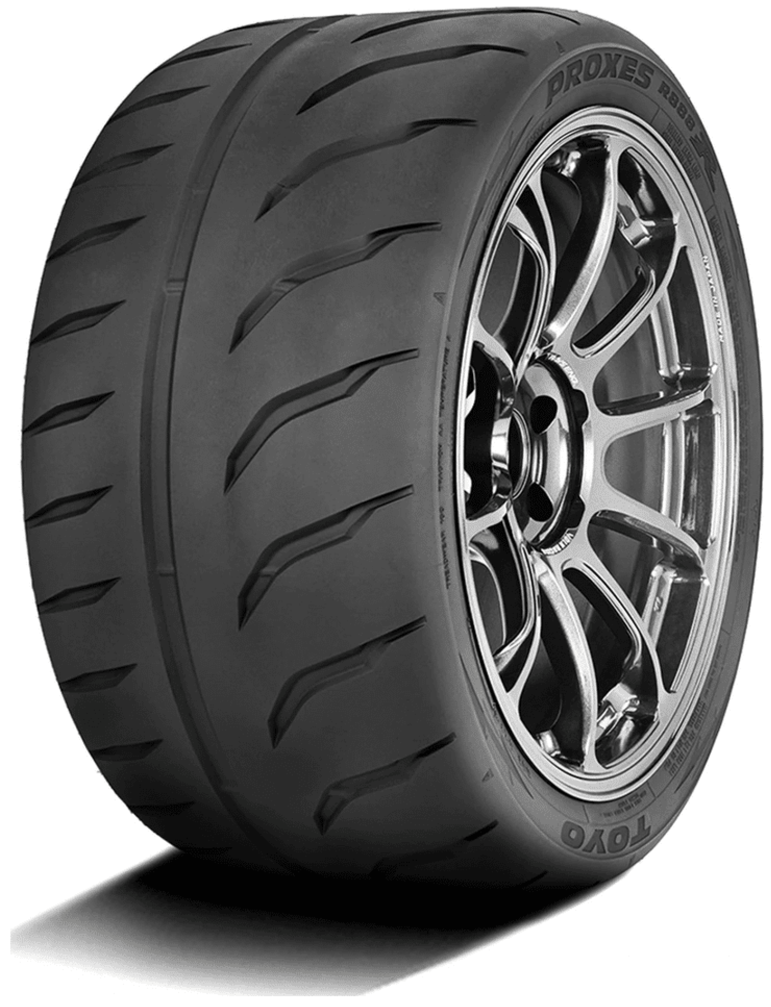
The tires used during these tests are ToyoR16 Toyo Proxes R888R 195/50 R16 (Figure 5).
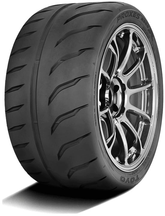
Figure 5.
ToyoR16 Toyo Proxes R888R 195/50 R16 used during the tests.
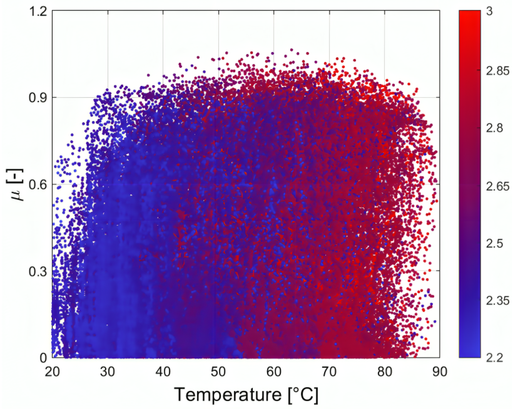
These particular tires are chosen for two fundamental reasons. The first reason is that they are high-performance wheels; their working range temperature is higher than that of the passenger wheels that are usually mounted under the road car, and this allows to bring the data to motorsport competitions in which the temperature is clearly higher than for road cars, which can be seen in Figure 6, in which the peak is about 60 ºC. The other reason is that slick tires in the road world are banned, and these Toyo are semi-slick because they still have grooves and therefore can run on common roads. This allows to use these acquisitions to validate the forces and slips that can be obtained in everyday passengers car by driving the car differently, and thus help not only the brake manufacturers of the motorsport world but also brake manufacturers for road cars in properly designing the braking system according to the forces to which the tire is subject.
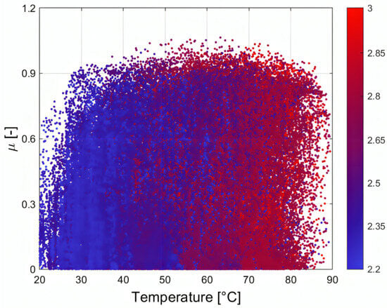
Figure 6.
Diagram of by varying the tire temperature.
The three different brake systems investigated differ in terms of the caliper type (fixed or floating) and material. The general parameters for each are the following:
- Piston Area: 18.74 cm2 for brake 1 and 2, 17.62 for brake 3;
- Effective Radius: 134 mm for brake 1, 111 mm for brake 2 and 105 mm for brake 3;
- Pad dimensions: 280 × 22 mm for brake 1 and 2275 × 20 mm for brake 3;
- Friction material: the Ferodo 4209 for all brake systems evaluated;
- Disk material: cast iron for all brake systems evaluated.
4. Results Validation
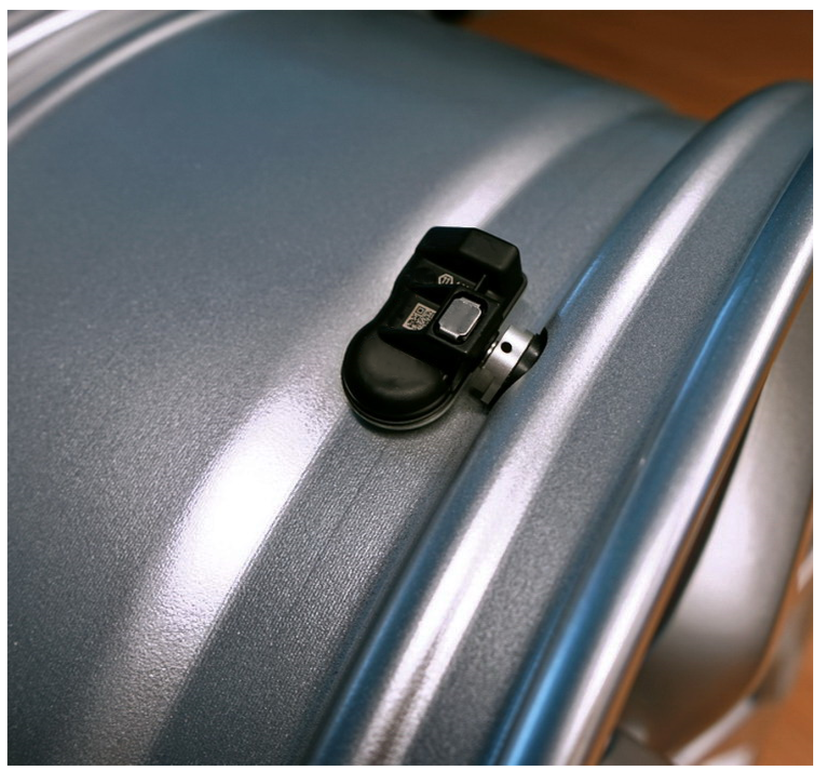
To evaluate how it works together with the thermal model of the tire, simulations were carried out to compare the wheel internal air pressure and the temperatures of the layers. The pressure value was measured with the TPMS sensor in Figure 7.
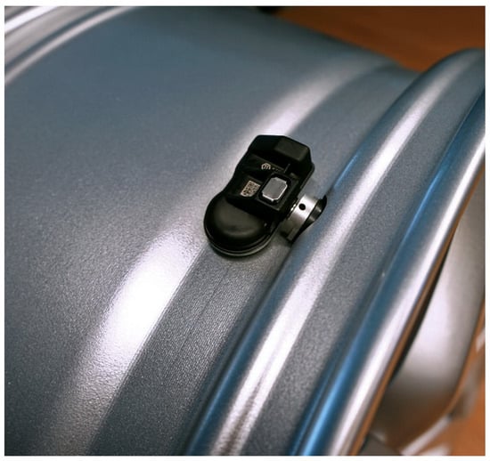
Figure 7.
TPMS sensor to measure pressure and temperature inside the tire.
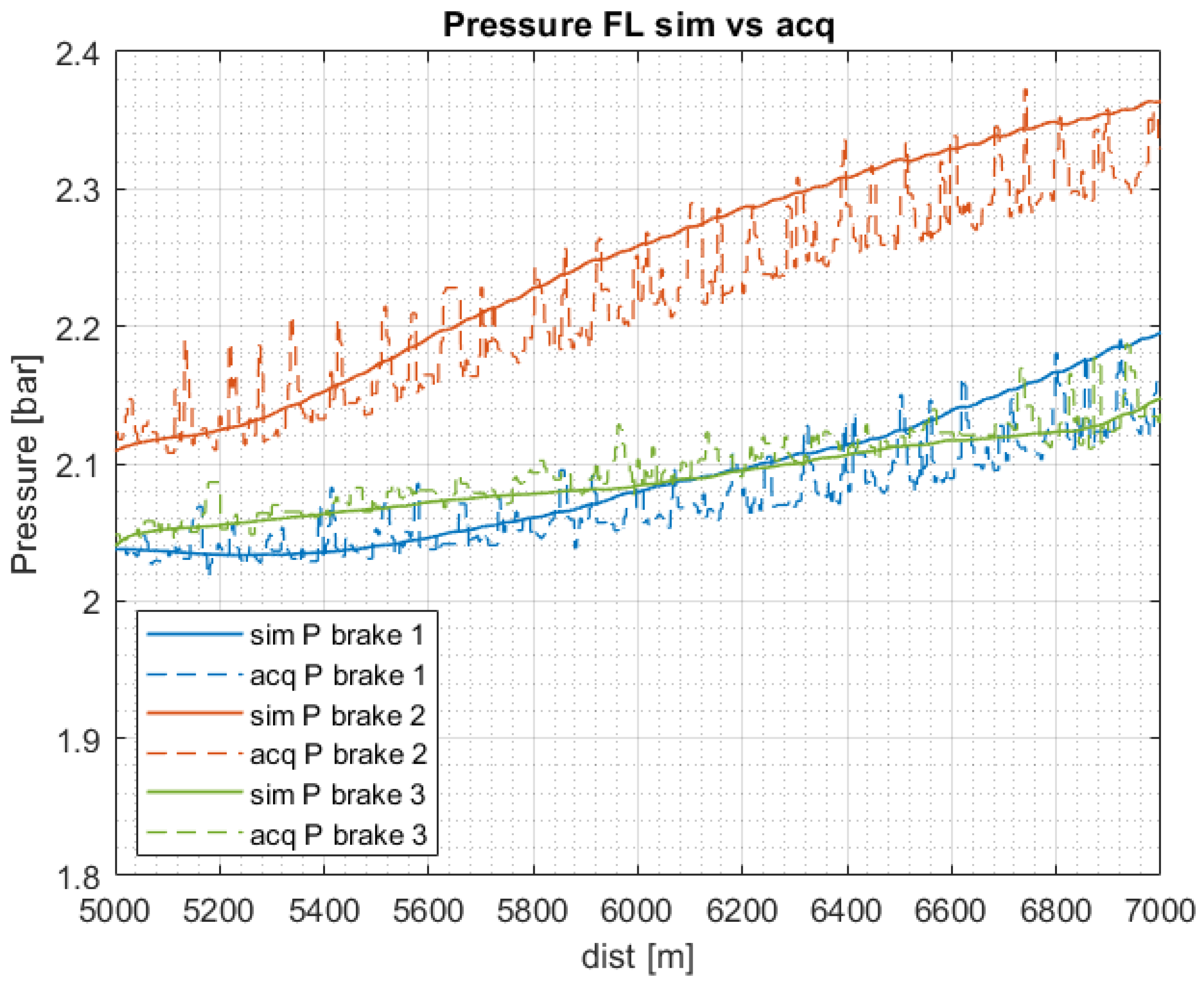
Figure 8 presents the comparison between the simulated internal air pressure (solid lines) and the acquisition values (dashed lines) for each braking system considered in a specific circuit sector of relevant importance. Obviously, the experimental model includes significantly higher frequencies of updates compared to the simulated model, which follows a smoother trajectory. As highlighted in the figure, the first two brake systems show a different behavior with respect to the other one in the final phase. The first reason for this behavior may lie in the different dimensions of the braking systems. It is also possible to observe that not all simulated curves are exactly positioned around the average value of the data purchases throughout the time history. In fact, you can see how the curve that resembles the second braking system in some sections is almost taken out of the acquired one.This is due to the fact that there was a need to find a trade-off for all simulations, as the tested tire was unique and, consequently, the parameters describing its thermodynamic behavior had to remain constant for each simulation. It is evident that these systems present a different pressure increase due to the diverse configurations. Furthermore, the first system reaches higher values since its initial condition is different from the others. This can be explained by the fact that the external environmental conditions were different.
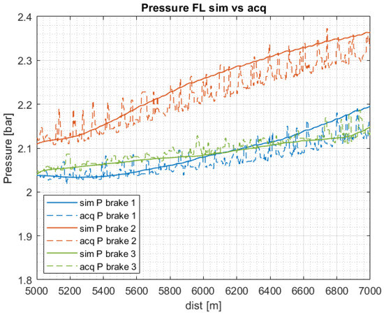
Figure 8.
Comparison between the simulated and acquired pressure.
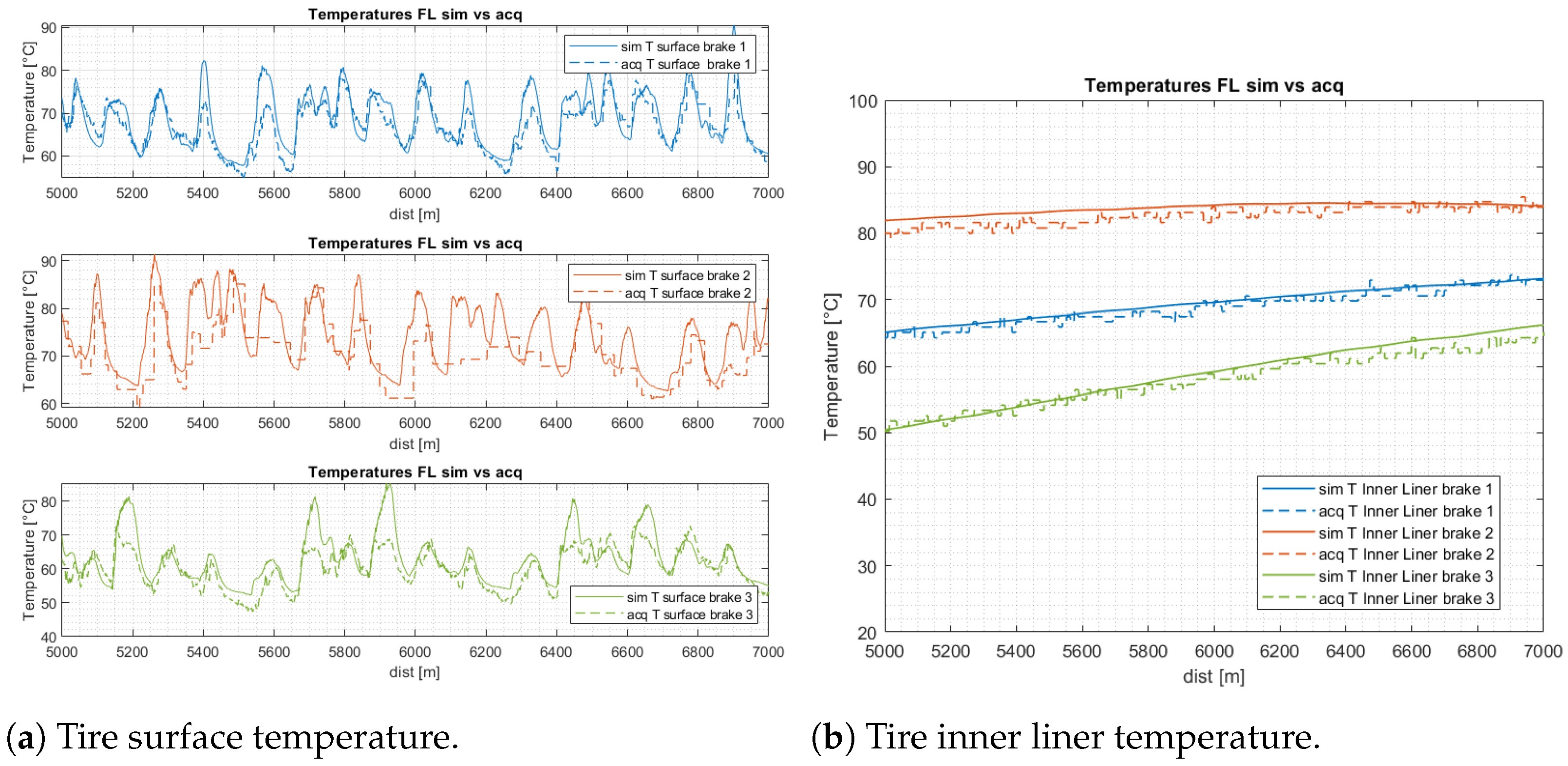
Figure 9a,b show the comparison between the simulated and the acquired temperatures of tire surface and inner liner. It can be seen that the simulated data tend toward the experimental ones. The results obtained are in agreement with the previous ones, as the inner liner temperature of the second system is higher than the others, as is also noted for the pressure. This is a fundamental aspect due to the fact that these two measures are strictly connected.
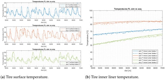
Figure 9.
Comparison between simulated and acquired surface (a) and inner liner (b) temperatures.
This result shows promise to be able to simulate the thermal trend of the brakes to vary the forces acting on the wheels and the type of brake configuration. The results show that different brakes can have a very different thermal trend depending on the material and the design on the brake itself, and this can also greatly affect the internal air temperature of the tire that leads to a great variation in terms of grip and vehicle performance.
5. Conclusions
In this paper, several braking systems provided by an industrial partner were compared with the aim of calibrating the integrated tire–brake model and simulating different thermal evolution examples with the aim of achieving maximum performance and safety. The tests were performed on an instrumented race vehicle. The experimental temperatures of the brakes were obtained through IR sensors. The temperature of the pads were installed inside the braking system through thermocouples, and the caliper temperatures were installed through the oil temperature of the braking system. As for the tire, the temperatures of the inner liner and the surface were obtained using IR sensors, and through the TPMS, the internal air pressure was obtained. The results shown in this work show how it is possible, starting from the simulation of the temperature of the brakes, to influence in a clear way the conditions of pressure and temperature of the tire, which affect the grip available and the performance of the vehicle. As the temperature of the brake varies its performance, it consequently can vary the control action to allow optimal braking under the various conditions of use to ensure maximum safety. This study also provides the basis for manufacturers to help design brake systems for the choice of design and materials.
Author Contributions
Conceptualization, A.S.; methodology, F.C. and P.C.; validation, A.S., M.A., F.R. and R.S.; formal analysis, F.R.; investigation, M.A.; resources, F.C. and P.C.; data curation, P.C.; writing—original draft, A.S., F.R. and R.S.; writing—review & editing, M.A., F.C. and P.C.; visulaization, F.C.; supervision, F.C. All authors have read and agreed to the published version of the manuscript.
Funding
This research received no external funding.
Data Availability Statement
Data sharing is not applicable to this article.
Conflicts of Interest
Authors Fabio Carbone and Pietro Caresia were employed by the company Brembo S.p.A. The remaining authors declare that the research was conducted in the absence of any commercial or financial relationships that could be construed as a potential conflict of interest.
References
- Farroni, F.; Sakhnevych, A. Tire multiphysical modeling for the analysis of thermal and wear sensitivity on vehicle objective dynamics and racing performances. Simul. Model. Pract. Theory 2022, 117, 102517. [Google Scholar] [CrossRef]
- Romano, L.; Sakhnevych, A.; Strano, S.; Timpone, F. A hybrid tyre model for in-plane dynamics. Veh. Syst. Dyn. 2019, 58, 1123–1145. [Google Scholar] [CrossRef]
- Romano, L.; Timpone, F.; Bruzelius, F.; Jacobson, B. Rolling, tilting and spinning spherical wheels: Analytical results using the brush theory. Mech. Mach. Theory 2022, 173, 104836. [Google Scholar] [CrossRef]
- Barbaro, M.; Genovese, A.; Timpone, F.; Sakhnevych, A. Extension of the multiphysical magic formula tire model for ride comfort applications. Nonlinear Dyn. 2024, 112, 4183–4208. [Google Scholar] [CrossRef]
- Niola, V.; Spirto, M.; Savino, S.; Cosenza, C. Vibrational analysis to detect cavitation phenomena in a directional spool valve. Int. J. Mech. Control. 2021, 22, 11–16. [Google Scholar]
- Calabrese, A.; Losanno, D.; Barjani, A.; Spizzuoco, M.; Strano, S. Effects of the long-term aging of glass-fiber reinforced bearings (FRBs) on the seismic response of a base-isolated residential building. Eng. Struct. 2020, 221, 110735. [Google Scholar] [CrossRef]
- Calabrese, A.; Quaglini, V.; Strano, S.; Terzo, M. Online estimation of the friction coefficient in sliding isolators. Struct. Control. Health Monit. 2020, 27, e2459. [Google Scholar] [CrossRef]
- Califano, F.; Cosenza, C.; Niola, V.; Savino, S. Multibody model for the design of a rover for agricultural applications: A preliminary study. Machines 2022, 10, 235. [Google Scholar] [CrossRef]
- Niola, V.; Savino, S.; Quaremba, G.; Cosenza, C.; Nicolella, A.; Spirto, M. Discriminant analysis of the vibrational behavior of a gas micro-turbine as a function of fuel. Machines 2022, 10, 925. [Google Scholar] [CrossRef]
- Teodosio, L.; Timpone, F.; dell’Annunziata, G.N.; Genovese, A. RANS 3D CFD simulations to enhance the thermal prediction of tyre thermodynamic model: A hierarchical approach. Results Eng. 2021, 12, 100288. [Google Scholar] [CrossRef]
- Teodosio, L.; Alferi, G.; Genovese, A.; Farroni, F.; Mele, B.; Timpone, F.; Sakhnevych, A. A numerical methodology for thermo-fluid dynamic modelling of tyre inner chamber: Towards real time applications. Meccanica 2021, 56, 549–567. [Google Scholar] [CrossRef]
- Ballo, F.; Stabile, P.; Gobbi, M.; Mastinu, G. A lightweight ultra-efficient electric vehicle multi-physics modeling and driving strategy optimization. IEEE Trans. Veh. Technol. 2022, 71, 8089–8103. [Google Scholar] [CrossRef]
- Genovese, A.; Strano, S.; Terzo, M. Design and multi-physics optimization of an energy harvesting system integrated in a pneumatic suspension. Mechatronics 2020, 69, 102395. [Google Scholar] [CrossRef]
- Genovese, A.; Pastore, S.R. Development of a portable instrument for non-destructive characterization of the polymers viscoelastic properties. Mech. Syst. Signal Process. 2021, 150, 107259. [Google Scholar] [CrossRef]
- Genovese, A.; Maiorano, A.; Russo, R. A novel methodology for non-destructive characterization of polymers’ viscoelastic properties. Int. J. Appl. Mech. 2022, 14, 2250017. [Google Scholar] [CrossRef]
- Sakhnevych, A.; Genovese, A. Tyre wear model: A fusion of rubber viscoelasticity, road roughness, and thermodynamic state. Wear 2024, 542–543, 205291. [Google Scholar] [CrossRef]
- Sakhnevych, A.; Genovese, A.; Maiorano, A.; Timpone, F.; Farroni, F. An ultrasound method for characterization of viscoelastic properties in frequency domain at small deformations. Proc. Inst. Mech. Eng. Part J. Mech. Eng. Sci. 2021, 235, 7180–7191. [Google Scholar] [CrossRef]
- Jodhani, J.; Handa, A.; Gautam, A.; Rana, R. Ultrasonic non-destructive evaluation of composites: A review. Mater. Today Proc. 2023, 78, 627–632. [Google Scholar] [CrossRef]
- Mosconi, L.; Farroni, F.; Sakhnevych, A.; Timpone, F.; Gerbino, F.S. Adaptive vehicle dynamics state estimator for onboard automotive applications and performance analysis. Veh. Syst. Dyn. 2023, 61, 3244–3268. [Google Scholar] [CrossRef]
- Strano, S.; Terzo, M.; Tordela, C. Output-only estimation of lateral wheel-rail contact forces and track irregularities. Veh. Syst. Dyn. 2023. [Google Scholar] [CrossRef]
- Kaiser, I.; Salvatore Strano, M.T.; Tordela, C. Estimation of the railway equivalent conicity under different contact adhesion levels and with no wheelset sensorization. Veh. Syst. Dyn. 2022, 61, 19–37. [Google Scholar] [CrossRef]
- Kaiser, I.; Strano, S.; Terzo, M.; Tordela, C. Anti-yaw damping monitoring of railway secondary suspension through a nonlinear constrained approach integrated with a randomly variable wheel-rail interaction. Mech. Syst. Signal Process. 2021, 146, 107040. [Google Scholar] [CrossRef]
- Gandelli, E.; Lomiento, G.; Quaglini, V.; Strano, S.; Terzo, M.; Tordela, C. Estimation of the instantaneous friction coefficients of sliding isolators subjected to bi-directional orbits through a nonlinear state observer. Eng. Struct. 2021, 249, 113374. [Google Scholar] [CrossRef]
- Li, Y.; Zuo, S.; Lei, L.; Yang, X.; Wu, X. Analysis of impact factors of tire wear. J. Vib. Control 2012, 18, 833–840. [Google Scholar] [CrossRef]
- Conant, F. Tire temperatures. Rubber Chem. Technol. 1971, 44, 397–439. [Google Scholar] [CrossRef]
- Mavros, G. A thermo-frictional tyre model including the effect of flash temperature. Veh. Syst. Dyn. 2019, 57, 721–751. [Google Scholar] [CrossRef]
- Calabrese, A.; Gandelli, E.; Quaglini, V.; Strano, S.; Terzo, M.; Tordela, C. Monitoring of hysteretic friction degradation of curved surface sliders through a nonlinear constrained estimator. Eng. Struct. 2021, 226, 111371. [Google Scholar] [CrossRef]
- Romagnuolo, F.; Avolio, S.; Fichera, G.; Ruffini, M.; Stefanelli, R.; Timpone, F. A Co-Simulation Platform with Tire and Brake Thermal Model for the Analysis and Reproduction of Blanking. Vehicles 2023, 5, 1605–1621. [Google Scholar] [CrossRef]
- Schlanger, H. A one-dimensional numerical model of heat transfer in the process of tire vulcanization. Rubber Chem. Technol. 1983, 56, 304–321. [Google Scholar] [CrossRef]
- Whicker, D.; Browne, A.; Segalman, D.; Wickliffe, L. A thermomechanical approach to tire power loss modeling. Tire Sci. Technol. 1981, 9, 3–18. [Google Scholar] [CrossRef]
- Guner, R.; Yavuz, N.; Kopmaz, O.; Ozturk, F.; Korkmaz, I. Validation of analytical model of vehicle brake system. Int. J. Veh. Des. 2004, 35, 331–348. [Google Scholar] [CrossRef]
- Bakar, A.; Abu, R.; Ouyang, H.; Khai, L.C.; Abdullah, M.S. Thermal Analysis of a Disc Brake Model Considering a Real Brake Pad Surface and Wear. Int. J. Veh. Struct. Syst. (IJVSS) 2010, 2, 20–27. [Google Scholar]
- Calabrese, F.; Baecker, M.; Galbally, C.; Gallrein, A. A detailed thermo-mechanical tire model for advanced handling applications. Sae Int. J. Passeng.-Cars-Mech. Syst. 2015, 8, 501–511. [Google Scholar] [CrossRef]
- Li, X.; Han, J.; Dai, X.; Zheng, Z.; Niu, Y. Monitoring overloaded trucks with infrared thermal imaging of tire sidewall. Heliyon 2024, 10, e34358. [Google Scholar] [CrossRef] [PubMed]
- Stoumpos, S.; Bolbot, V.; Theotokatos, G.; Boulougouris, E. Safety performance assessment of a marine dual fuel engine by integrating failure mode, effects and criticality analysis with simulation tools. Proc. Inst. Mech. Eng. Part J. Eng. Marit. Environ. 2022, 236, 376–393. [Google Scholar] [CrossRef]
- Terzo, A.; Gobbato, P.; Masi, M.; Rossi, A. An engine/vehicle model to assess the theoretical increase of car safety by using the spark ignition engine to support the conventional braking system. Int. J. Thermodyn. 2016, 19, 187–196. [Google Scholar]
- Ilie, F.; Cristescu, A.C. Tribological behavior of friction materials of a disk-brake pad braking system affected by structural changes—A review. Materials 2022, 15, 4745. [Google Scholar] [CrossRef]
- Sethupathi, P.B.; Chandradass, J.; Saibalaji, M. Comparative study of disc brake pads sold in Indian market—Impact on safety and environmental aspects. Environ. Technol. Innov. 2021, 21, 101245. [Google Scholar] [CrossRef]
- Kreith, F.; Bohn, M. Principles of Heat Transfer, St; Paul: West Publishing Company: Eagan, MT, USA, 1993. [Google Scholar]
- Stevens, K.; Tirovic, M. Heat dissipation from a stationary brake disc, Part 1: Analytical modelling and experimental investigations. Proc. Inst. Mech. Eng. Part J. Mech. Eng. Sci. 2018, 232, 1707–1733. [Google Scholar] [CrossRef]
- Rout, S. Design and Analysis of Brake Disc. Ph.D. Thesis, Veer Surendra Sai University of Technology, Odisha, India, 2018. [Google Scholar]
- Thakur, A.S.; Dhakad, P. Thermal analysis of disc brake using ANSYS. Int. J. Tech. Innov. Mod. Eng. Sci. 2018, 4, 8–17. [Google Scholar]
- Day, A.J.; Bryant, D. Braking of Road Vehicles; Butterworth-Heinemann: Oxford, UK, 2022. [Google Scholar]
- Antanaitis, D.; Monsere, P.; Riefe, M. Brake system and subsystem design considerations for race track and high energy usage based on fade limits. SAE Int. J. Passeng.-Cars-Mech. Syst. 2008, 1, 689–708. [Google Scholar] [CrossRef]
Disclaimer/Publisher’s Note: The statements, opinions and data contained in all publications are solely those of the individual author(s) and contributor(s) and not of MDPI and/or the editor(s). MDPI and/or the editor(s) disclaim responsibility for any injury to people or property resulting from any ideas, methods, instructions or products referred to in the content. |
© 2024 by the authors. Licensee MDPI, Basel, Switzerland. This article is an open access article distributed under the terms and conditions of the Creative Commons Attribution (CC BY) license (https://creativecommons.org/licenses/by/4.0/).

