Abstract
The introduction of advanced driver assistance systems has significantly reduced vehicle accidents by providing crucial support for high-speed driving and alerting drivers to imminent dangers. Despite these advancements, current systems still depend on the driver’s ability to respond to warnings effectively. To address this limitation, this research focused on developing a neural network model for the automatic detection and classification of objects in front of a vehicle, including pedestrians and other vehicles, using radar technology. Radar sensors were employed to detect objects by measuring the distance to the object and analyzing the power of the reflected signals to determine the type of object detected. Experimental tests were conducted to evaluate the performance of the radar-based system under various driving conditions, assessing its accuracy in detecting and classifying different objects. The proposed neural network model achieved a high accuracy rate, correctly identifying approximately 91% of objects in the test scenarios. The results demonstrate that this model can be used to inform drivers of potential hazards or to initiate autonomous braking and steering maneuvers to prevent collisions. This research contributes to the development of more effective safety features for vehicles, enhancing the overall effectiveness of driver assistance systems and paving the way for future advancements in autonomous driving technology.
1. Introduction
Radar technology is increasingly used to detect both moving and stationary objects [1]. The word “radar”, from “radio detection and ranging”, means not only the detection of objects, but also the evaluation of certain parameters of these objects at the same time.
Radars emit a radio pulse, which is reflected by the target and typically received at the same position as the emitter. This “echo” allows for the extraction of a great deal of information [2]. The reflection of radar waves varies according to their wavelength and the shape and properties of the target. When the object is much smaller than the wavelength, it becomes invisible to the wave, that is, the wave passes through it as if it did not exist. When the sizes are similar, a part of the wave energy is reflected and another portion passes through the object, resulting in the diffraction effect [3]. Early radars used very long wavelengths, larger than the targets, which resulted in weak echo signals. Today’s radars use small wavelengths (a few centimetres or less) that allow objects the size of a human arm to be detected. Short-wave signals (3 kHz–30 MHz) reflect off curves and edges, just as light flashes off a curved piece of glass. The radar cross section (RCS) of an object is a key factor that determines the degree of reflectance of radio waves [4].
Radar sensors can also be used to measure velocities thanks to the Doppler effect [5]. By taking advantage of the fact that the return signal from a moving target is frequency shifted, it is possible to measure the relative velocity of the object with respect to the radar. The velocity components perpendicular to the radar line of sight cannot be estimated by the Doppler effect alone and would require memory to calculate them by tracking the evolution of the target’s position [6].
It is not uncommon to find radars integrated with other sensors in order to achieve complex applications. Some of the most noticeable uses of this technology integration include the following:
- Object tracking and classification [7,8,9,10,11,12].
- Non-contact heart and breathing rate estimation [13,14,15,16].
- Vehicle platoon control [17,18,19,20].
- Human gait recognition [21,22,23].
Specifically in the vehicle research field, the development of advanced driver assistance systems (ADASs) has led to a significant decrease in the number of traffic accidents [24,25]. ADASs commonly incorporate radar sensors to facilitate multiple tasks, such as cruise control, to automatically slow down or speed up the vehicle to maintain a set gap with the vehicle ahead [26]; emergency braking, where a vehicle may decelerate sharply without driver involvement in order to avoid a potential collision [27]; blind spot detection, where radar sensors are used to monitor the blind spots and alerts the driver in the event of a potential collision when changing lanes [28]; parking assistance, to precisely detect an open parking space nearby [29]; etc.
The integration of multiple sensors in ADASs will result in a significant computational burden, which may not be feasible in real-time applications with low-cost architectures [30,31]. Although it is now relatively inexpensive to include additional sensors in vehicles, we were curious as to whether a single sensor would be sufficient for some applications. Moreover, concerning radar features, most are based solely on the analysis of the distance and velocity measured from the radar, which fail to utilise the full potential of radar sensors. While it is often forgot that the RCS of an object determines how waves are reflected, numerous studies can been found on RCS reduction, useful for military and defence applications [32,33,34]. If the RCS is sufficiently low, the object cannot be detected. However, in detectable objects, the reflected power at a given distance will differ according to the object properties. In [35], the RCS and Doppler signature of targets are used to differentiate pedestrians and vehicles; however, targets can be stationary or there can be no observable Doppler signature, which limits the practical application. In [36], machine learning techniques are applied for target classification under static conditions. For some advanced radars that are capable of imaging, targets can be represented by radar images, as in [37], where targets are visualized as radar point clouds, discarding RCS and Doppler data. Nevertheless, the aforementioned sensors are prohibitively expensive and therefore unsuitable for inclusion in series production vehicles. The results of these works have led to the formulation of the following hypothesis: is it possible to detect and identify vehicles and pedestrians solely through the use of low-cost radar information such as RCS and distance?
The objective of this paper is to design a system for detecting and identifying objects in front of a vehicle, exclusively using two radar measurements: distance to the target and reflected power, which is correlated with the RCS of the target. A frequency-modulated continuous-wave (FCMW) radar was mounted on a vehicle during the experiments. A neural network was designed to classify each pair of measurements with the appropriate object. This information is provided to the user in order to assist them in driving. It can be used as part of ADAS systems in order to perform the appropriate response to a given stimulus. This may involve adapting the vehicle speed or performing emergency maneuvers in hazardous situations, such as when a pedestrian crosses the road unexpectedly, thereby enhancing safety. Potential applications of the proposed system include, but are not limited to, adaptive cruise control, automated emergency braking systems, and collision avoidance.
The manuscript is structured as follows: In Section 2, the fundamental principles of radar are formulated. In Section 3, a brief description of neural networks is provided. In Section 4, the experimental setup employed in this study is described. In Section 5, the experimental results are processed and a neural network is trained to identify the objects detected. In Section 6, the conclusions and future works related to this research are presented.
2. Radar Sensor
Radars emit a radio pulse, which is reflected when a target is hit. The reflected power to the radar receiving antenna is given by the following expression:
where is the reflected power, is the transmitter power, is the gain of the transmitting antenna, is the effective area of the receiving antenna, is the radar cross section of the target (typical RCS values are presented in Table 1), F is the pattern propagation factor (as reference, in a vacuum), is the distance from the transmitter to the target, and is the distance from the receiver to the target. In most common applications, transmitting and receiving antennas are located together, then , where R is the distance to the target.

Table 1.
Typical RCS values [38,39].
The use of separate transmit and receive antennas is recommended as it provides greater sensitivity and isolation. In the case of limited space and the only option being one common antenna, the receiver antenna can be removed. However, the received signal must be decoupled from the shared transmit/receive path, which results in a deterioration of data reception, with reduced sensitivity, as the received signal is fed into two ports: receive and transmit, where it is lost.
2.1. Pulse Radar
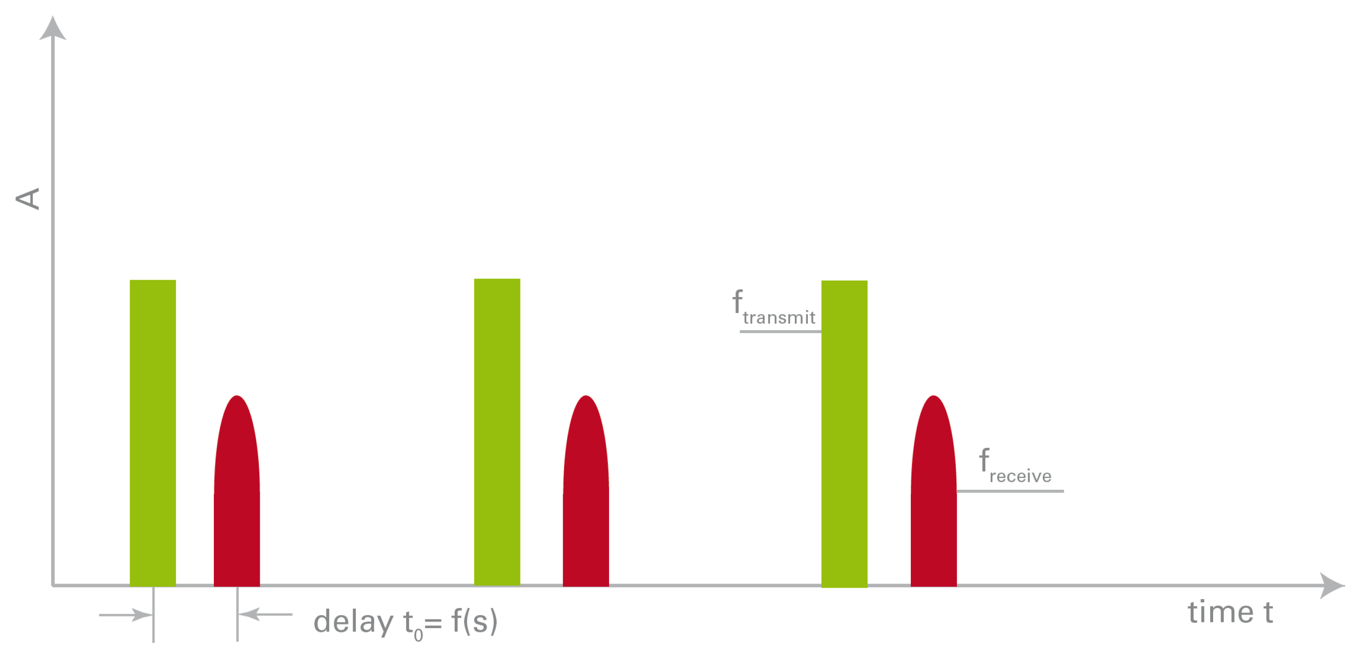
One method for measuring the distance between a radar and an object is to transmit a small electromagnetic pulse and subsequently measure the time taken for the echo to return (Figure 1) [40].
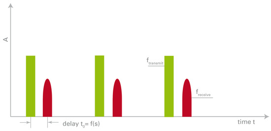
Figure 1.
Time-dependent shape of transmit and receive signal of a pulse radar [41].
In order to have a good resolution, especially for objects at close range, these pulses must be very short. The distance can be calculated as half the transit time multiplied by the propagation speed of the pulse. The accurate estimation of distance necessitates the utilisation of high-performance electronic components. The majority of radars utilise the same antenna for both sending and receiving; therefore, during the transmission of the pulse, no echo can be received. This establishes the so-called “blind distance” of the radar, below which the radar is rendered ineffective [42].
2.2. FMCW Radar
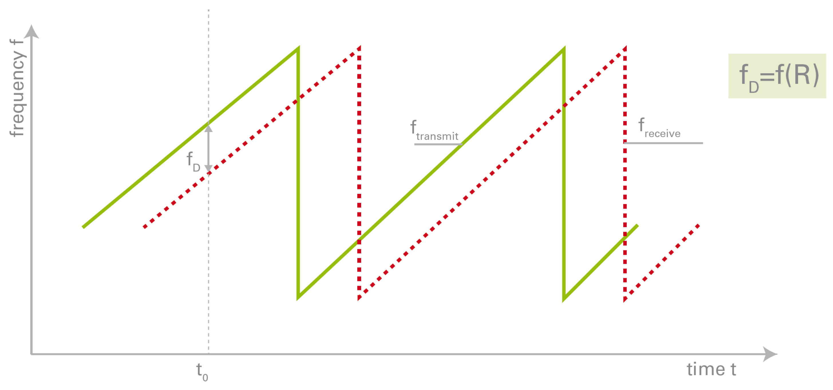
Frequency-modulated continuous-wave (FMCW) radar represents a different approach to detect stationary objects [43,44,45]. The comparison of frequencies is a more accurate and simpler method than the comparison of times. To achieve this, a sinusoidal signal is emitted at a frequency that varies continuously over time. Consequently, when the echo arrives, its frequency will differ from that of the original signal. By comparing the two signals, it is possible to ascertain the elapsed time and therefore the distance to the target (see Figure 2). The greater the frequency offset, the greater the distance, calculated using the following formula:
where is the speed of light, T is the sawtooth repetition time period, is the differential frequency and is the frequency deviation.
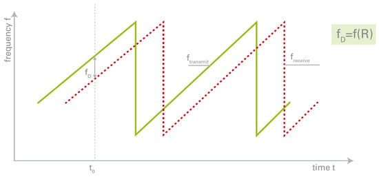
Figure 2.
Time-dependent shape of transmit and receive signal of a FMCW radar with sawtooth modulation scheme [41].
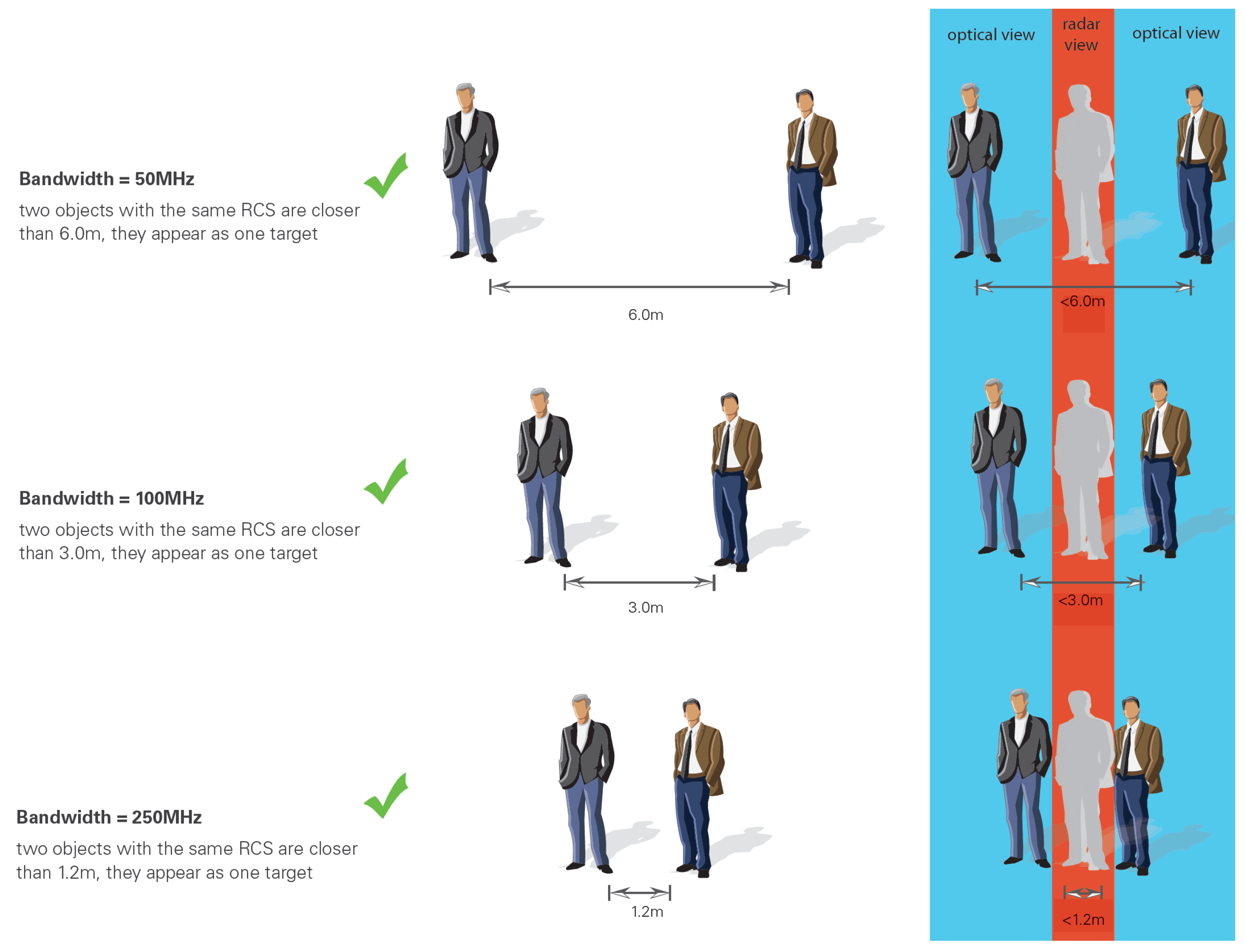
The accuracy of the measurement is dependent upon the bandwidth utilised. Furthermore, it is important to note that the laws of each country define which frequencies are permitted and which are prohibited. In the event that the bandwidth is insufficient, two distinct objects may be erroneously identified as a single entity, see Figure 3. A bandwidth higher than 250 MHz is not allowed because of regulation reasons in Europe (ETSI 300-440) and US (FCC 15.245). Therefore the best achievable resolution for the commercial radar iSYS-4004 used in this work is limited to 60 cm [41].
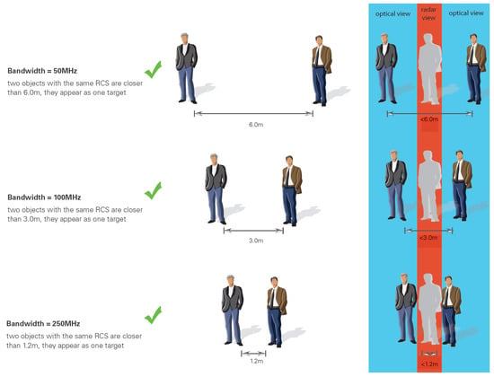
Figure 3.
Example of the bandwidth effect on the commercial radar iSYS-4004 [41].
3. Neural-Network-Based Identification
Artificial neural networks are computational systems inspired by the biological neural networks that are part of animal brains. Such systems are capable of learning to perform tasks through the feeding of a large set of examples, typically without the need for any task-specific rules to be programmed into them [46]. A neural network is based on a collection of interconnected units, or nodes, which are analogous to the neurons in a biological brain. Each connection functions in a manner analogous to synapses in a biological brain, transmitting a signal from one artificial neuron to another. An artificial neuron that receives a signal can process it and then signal additional artificial neurons that are connected to it.
In typical implementations, the signal at a connection between artificial neurons is a real number, and the output of each artificial neuron is calculated by some nonlinear function of the sum of its inputs. The connections between artificial neurons are designated as “edges”. The weights of the artificial neurons and edges are typically adjusted as the learning process progresses. The weight of the connection affects the strength of the signal transmitted at that point. It is possible for artificial neurons to have a threshold, whereby the signal is only transmitted if the aggregated signal crosses that threshold. Artificial neurons are typically aggregated in layers. The various layers are capable of implementing distinct types of transformations on their inputs. Signals are transmitted from the initial layer, designated the input layer, to the final layer, the output layer. This transmission can be performed in multiple stages, with signals passing through one or more intermediate layers.
An artificial neural network is composed of the following:
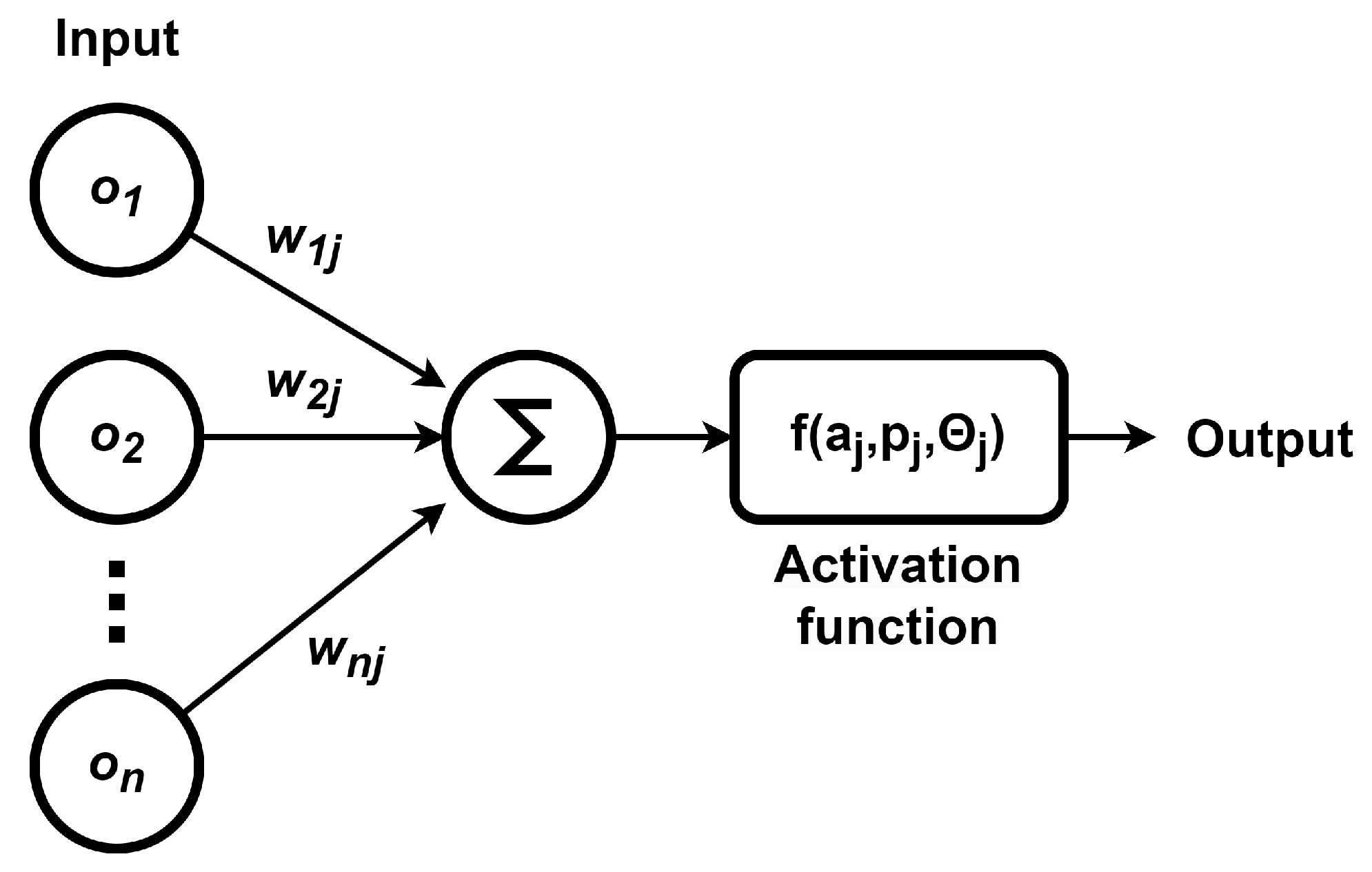
- Neurons. A neuron j (see Figure 4) that receives an input from the predecessor neurons has the following components:
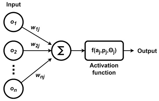 Figure 4. Artificial neuron.
- -
- An activation .
- -
- A threshold , which is usually fixed, unless a learning function updates it.
- -
- An activation function f, which evaluates the new activation in the following instant , using , , and the new input , leading toThe most commonly used activation functions are as follows [47]:
- *
- Sigmoid. The sigmoid activation function converts an input from range to the range . The sigmoid function is usually used in the output layer for classification purposes. One of the benefits of the sigmoid function is that it has a smooth derivative. The sigmoid activation function is defined as follows:
- *
- Hyperbolic tangent. This has a similar structure to the sigmoid function; however, the output is within the range . Compared to the sigmoid function, the hyperbolic tangent has a higher derivative. The hyperbolic tangent function is defined as follows:
- *
- Rectified linear unit (ReLU). This is a frequently employed activation function that returns the value of the input if it is positive; otherwise, it returns zero. The ReLU function is defined as follows:
- *
- Parametric leaky version of a ReLU (PReLU). In this case, instead of the function being zero for negative inputs, it returns a small negative slope . The PReLU function is defined as follows:
- *
- Exponential linear unit (ELU). This function provides some improvement to ReLU. The ELU activation function is defined as follows:
- *
- Scaled exponential linear unit (SELU). Another variation to ReLU. The SELU activation function is defined as follows:
- *
- Swish. The Swish function does not have an upper bound. The Swish function is defined as follows:
- *
- Mish. A variant with a similar shape to the Swish function. The Mish function is defined as follows:
- -
- An output signal that computes the activation outputIn the majority of cases, the output function is the identity function.
- Connections and weights. The neural network is based on connections. Each connection transmits the output of the neuron i to the input of the neuron j. Each connection is assigned the weight .
- Propagation functions. These calculate the input to the neuron j depending on the outputs from the predecessor neurons. A common propagation function is
- Learning rules. The learning rule is a rule or algorithm that modifies the parameters of the neural network in order to produce a desired outcome when presented with a specific input. This learning process involves modifying the weights and thresholds of variables within the network.
The network topology indicates the existence of two broad categories of artificial neural networks, which can be distinguished by the following characteristics:
- Feedforward neural network. This is the first and simplest type. In this network, the transfer of information occurs in a unidirectional manner, from the input layer to the output layer, without any loops. The process of learning occurs through the updating of connection weights in response to the processing of each piece of data, with the subsequent evaluation of the error between the actual and expected results.
- Recurrent neural network. These networks propagate data forward, but also backwards, from later processing stages to earlier stages. It is possible that recurrent neural networks may exhibit chaotic behaviour due to the backpropagation process.
The addition of further hidden layers to a neural network can enhance its performance, enabling it to learn more complex and abstract data representations, which are beneficial for tasks such as image recognition and natural language processing. However, this increases the number of parameters, computational requirements, and training time. The addition of excessive layers can result in overfitting, whereby the network performs well on training data but poorly on test data.
The capabilities of neural networks can be broadly categorised into the following areas:
- Function approximation or regression analysis, including time series prediction, fitness approximation and modelling.
- Classification, pattern and sequence recognition.
- Data processing, filtering and clustering.
- Robotics and control.
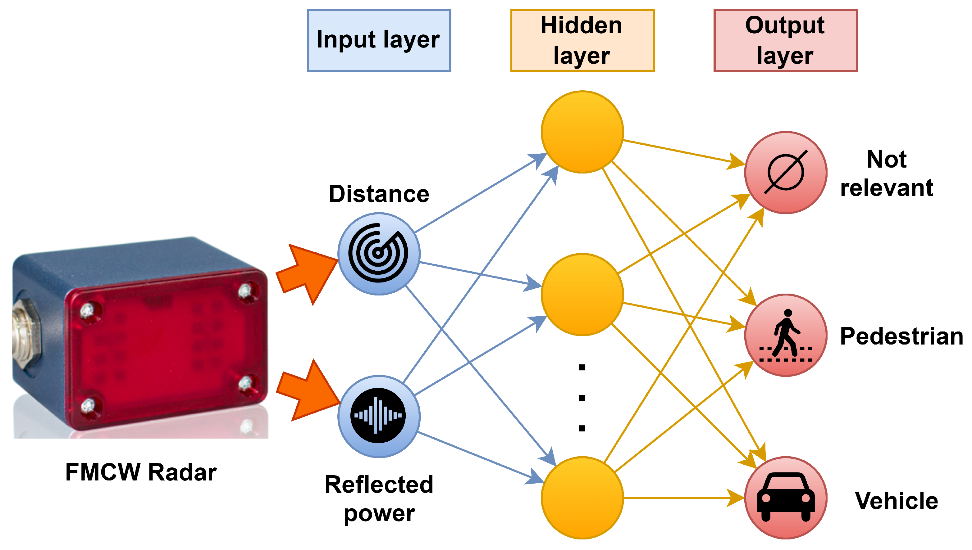
In order to detect and differentiate objects in the course of traffic, a neural network is to be designed which, by means of two input parameters (distance to the target and intensity of the signal returned by the object), is capable of determining whether the object detected is a person, a car, or nothing relevant.
The network is then constructed with two inputs: distance to target in metres and signal intensity in decibels; and three logical outputs: one for people, another for vehicles, and a third for irrelevant objects. The neural network will have two layers: one in which the neurons interpret the input values, and another, the output layer, which will provide the logic outputs based on the output values of the previous layer. In order to obtain a binary value for the object identification, a sigmoid activation function is to be used in the output layer. The network will be configured in a feedforward topology at each layer in order to reduce its overall complexity and the time required for learning. The learning process is supervised, which requires the training of the network with a substantial number of previously acquired and personally processed datasets derived from experimental tests. The greater the quantity of data utilised in the design of the network, the more reliable the resulting model will be. Two potential outcomes may be observed:
- In the event that the network functions as intended, with a low error rate, it can be applied to develop an autonomous driving system.
- In the event that the network exhibits a high number of errors, it is not reliable. In such instances, it is necessary to attempt to modify the number of neurons in the network, the data set with which it is trained, or the additional input parameters.
4. Experimental Setup
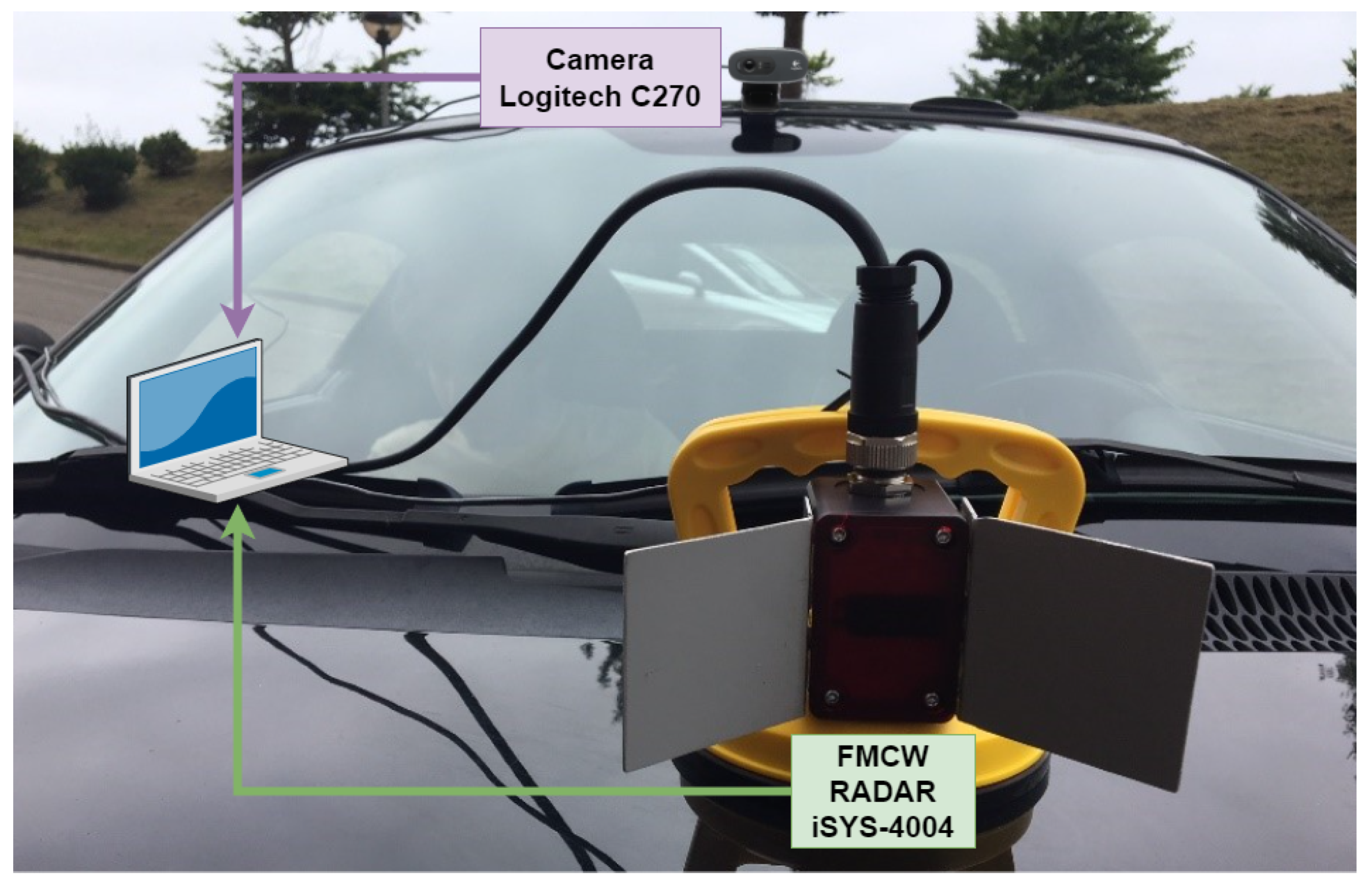
Figure 5 presents the architecture mounted on the vehicle. The experiments are recorded using a Logitech C270 camera. A commercial radar model, the iSYS-4004 from InnoSent, is employed for detecting objects. The technical specifications of the radar iSYS-4004 are presented in Table 2. Both the camera and the radar are connected to a laptop, on which the algorithms for object detection and identification are executed.
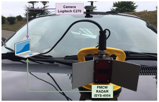
Figure 5.
Mounting of the radar on the vehicle.

Table 2.
Technical specifications of the radar iSYS-4004 [41].
The configuration presented here is designed to detect and identify vehicles and pedestrians in front of the vehicle. It should be noted that the radar is mounted on the vehicle bonnet and not on the front bump, in order to ensure that the minimum detection distance of 1.1 m is always met. The radar system is only capable of detecting the first object in front of the vehicle, and thus, the density of vehicles and pedestrians during driving does not affect the radar measurements.
For each object detected by the radar, two measurements must be analysed: the distance to the target and the reflected power, which is related to the object RCS. From that, a neural network will be designed so that it is capable of detecting and identifying pedestrians and vehicles. Any other object must be ignored. The procedure for processing the radar-measured information is illustrated Figure 6.
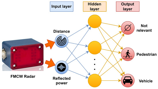
Figure 6.
Processing of radar information by a neural network for object detection and identification.
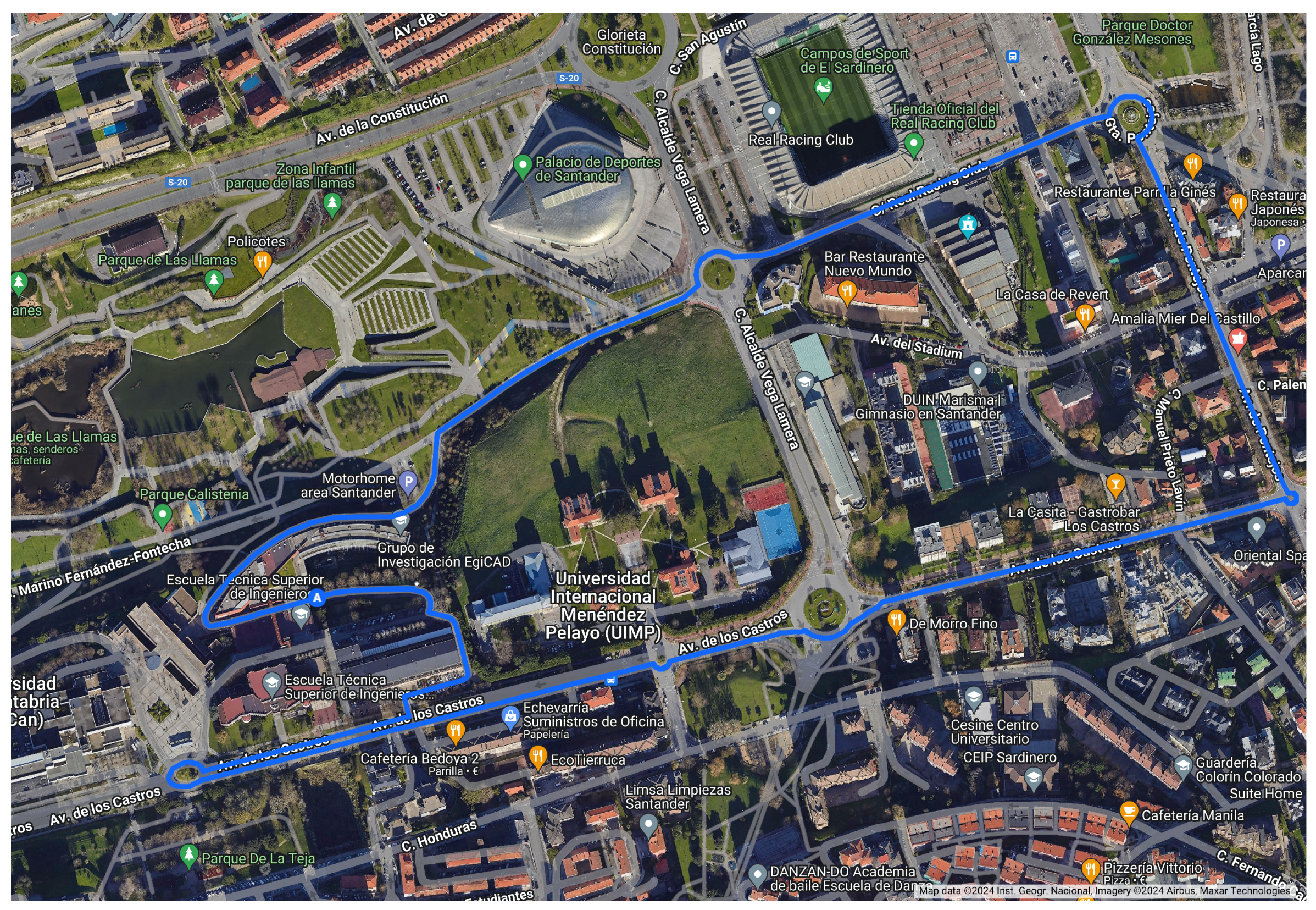
A series of experiments were conducted at different times of the day (morning, afternoon, evening, night) in the city of Santander, Spain. The experiment route is presented in Figure 7. From the initial processing of radar data, it has been demonstrated that the intensity of the signal returned by a vehicle is significantly greater than that returned by a person, and that these signals are distinct from those returned by other types of objects found on the road, such as traffic signs and rubbish bins. This is why the use of a neural network to differentiate each detection and classify it according to the type of object that produces it is an appropriate solution for the aim of the work. Further details will be provided in the subsequent section.
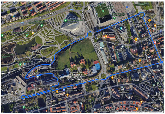
Figure 7.
Route followed during the experiments.
5. Experimental Results
A set of 2131 different objects were detected during driving using the experimental setup presented in Section 4. While the radar measured the distance to the target and reflected power, the user must first identify the objects in order to train the neural network for object detection and identification. Table 3 presents a sample of the data collected, which will constitute the input–output data employed in the training of the network. The first two columns are the input vectors, with the distance to the object and the intensity of the signal reflected. The final three columns represent the desired output vectors, which comprise three binary values indicating the type of object detected (pedestrian, vehicle or none of the above).

Table 3.
Sample input–output data from the neural network neural network.
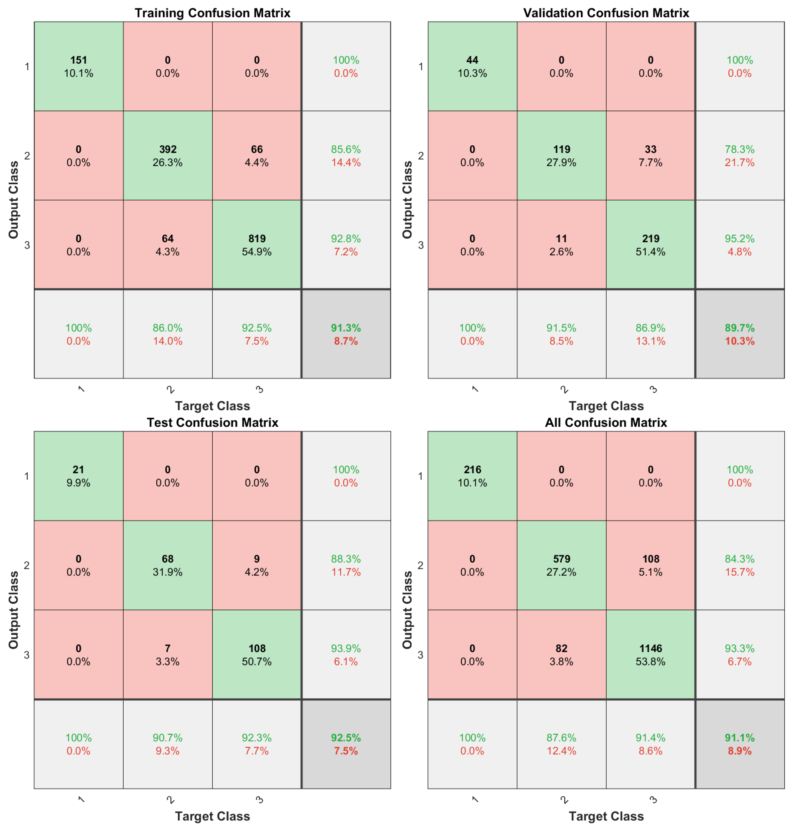
The collected data are then interpreted using the Deep Learning Toolbox from Matlab version 2024a, resulting in the generation of a neural network that contains 30 neurons in a hidden layer and 3 neurons in the output layer. A training set with 70% of the data is used to train the network, a validation set with 20% of the data is used to validate the generated network, and a test set with the remaining 10% of the data is used to test the performance of the network. During the training process, the data division is random, the training method chosen is the scaled conjugate gradient, and cross-entropy is selected as a performance indicator. Classes 1, 2 and 3 denote irrelevant objects, pedestrians, and vehicles, respectively. The network constructed from the dataset returned the confusion matrices presented in Figure 8, which indicates an overall 91.1% identification performance. Subsequent trials employed a residual neural network, resulting in an accuracy of 81%. Notably, this value is considerably inferior to the proposed solution, and thus, the use of a residual neural network was discarded.
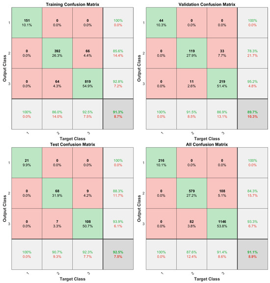
Figure 8.
Training, validation, test, and global confusion matrices.
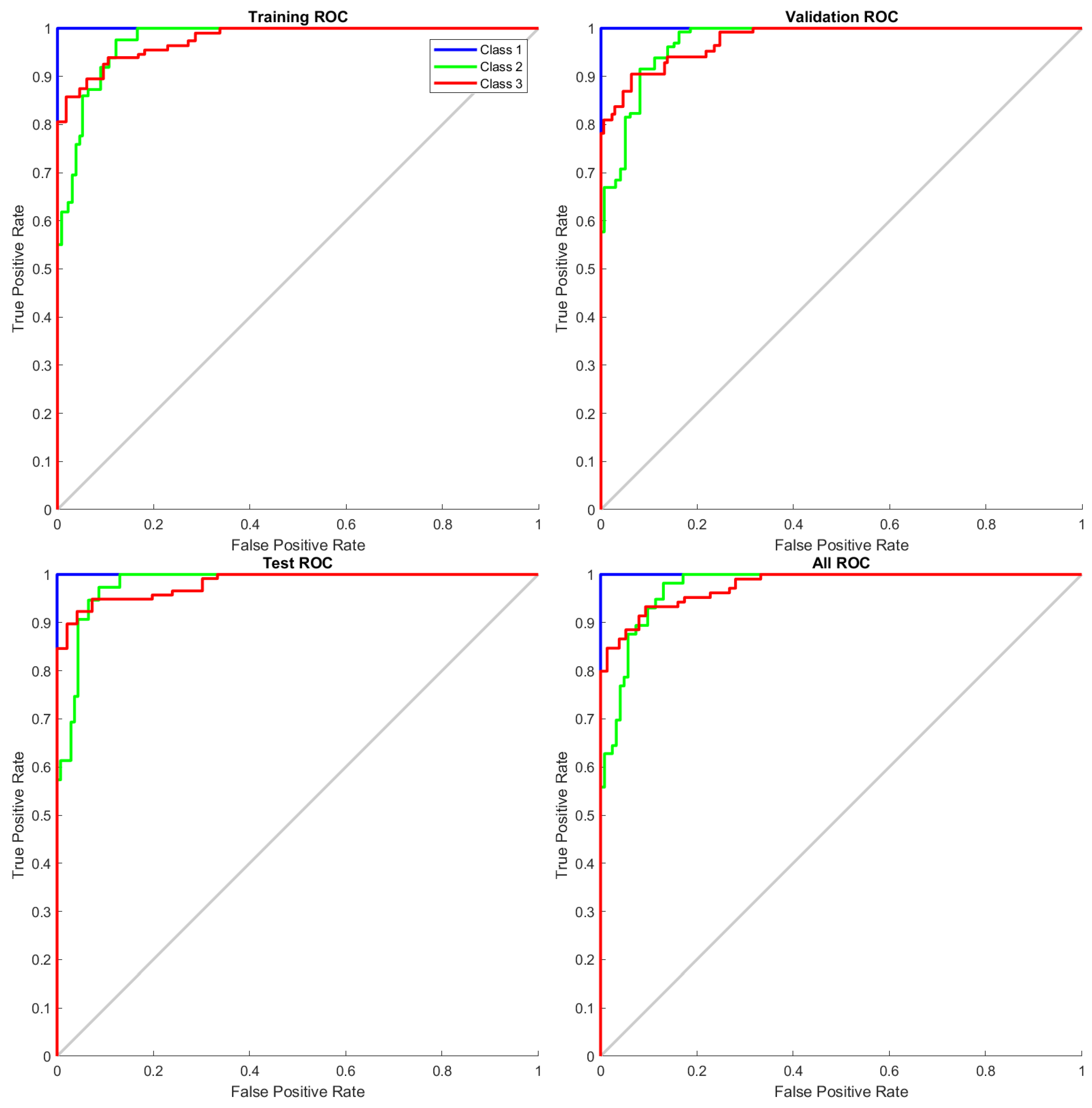
The true positive rate (TPR) against the false positive rate (FPR) of the proposed network is presented using the receiver operating characteristic curve (ROC), shown in Figure 9. It is important to note that pedestrians and vehicles are never misidentified as irrelevant objects. Furthermore, there are no irrelevant objects misidentified as pedestrians or vehicles. Although pedestrians can be misidentified as vehicles, this is not a severe issue: in the event that a pedestrian is erroneously identified as a vehicle, a possible safety protocol would adopt a cautious approach, such as slowing down or stopping, to avoid collisions. This conservative approach ensures that safety is maintained despite occasional classification errors.
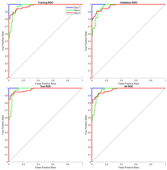
Figure 9.
ROC curve of the neural network.
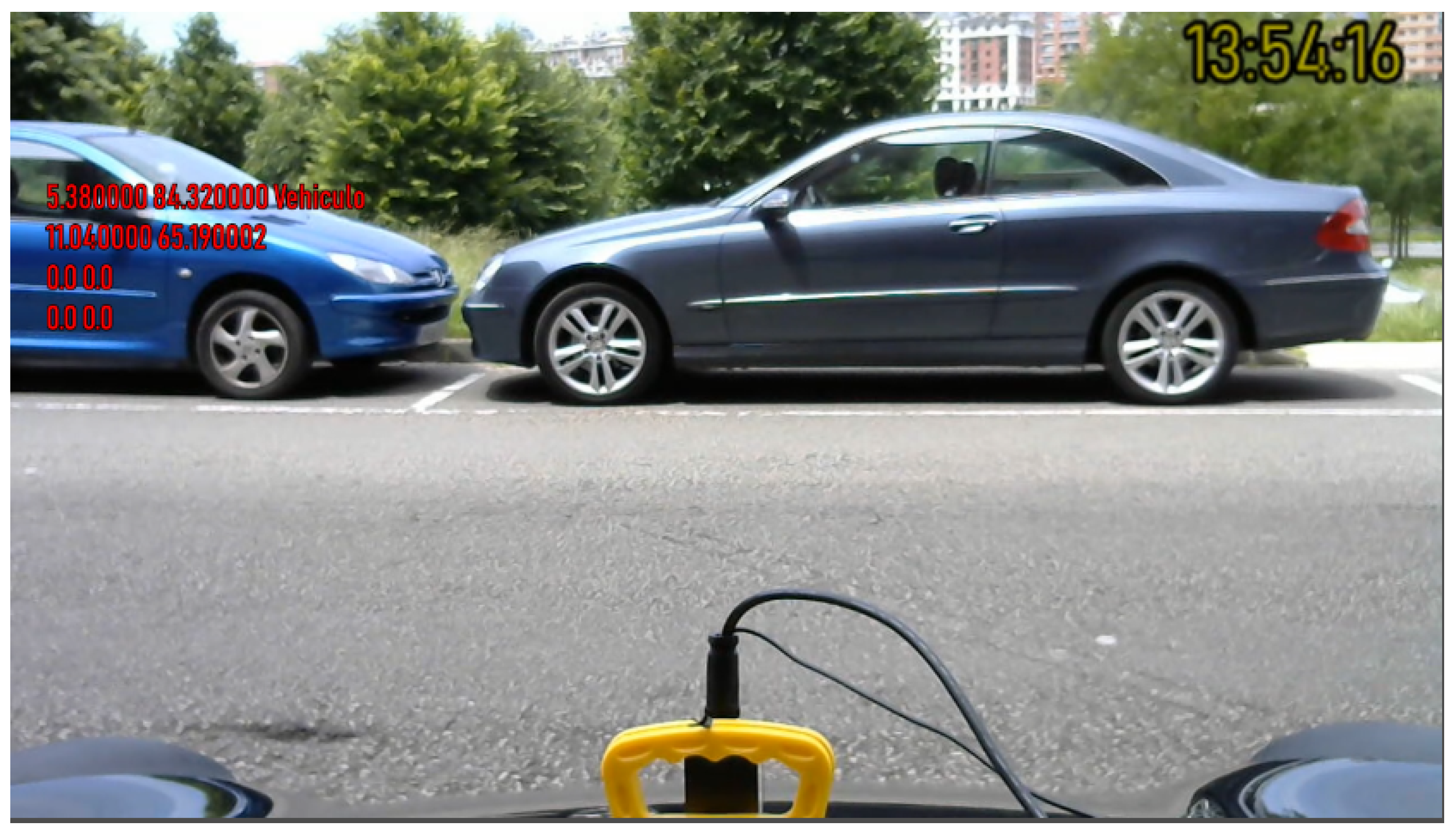
After the network had been designed, it was implemented on the vehicle architecture in order to detect objects in real time and to assist the driver, as seen in Figure 10. The aforementioned results have demonstrated the veracity of the hypothesis that it is possible to detect and identify vehicles and pedestrians solely through the use of low-cost radar information such as RCS and distance, which validates our work.
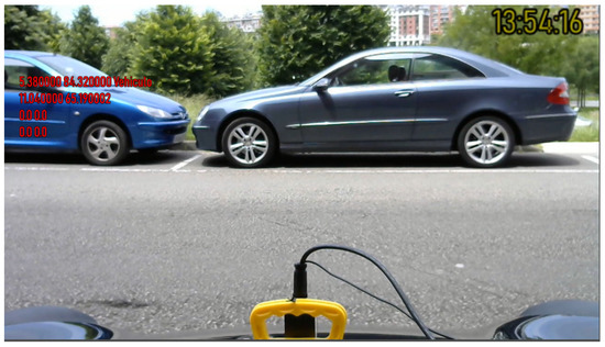
Figure 10.
On-screen display of radar data. Distance and type of objects.
6. Discussion and Conclusions
A pedestrian and vehicle detection and identification system has been developed based on a FCMW radar and a neural network. The radar provides the distance and intensity of the signal reflected by the nearest object, which constitute the input vector to the network. The network outputs a vector of three binary components, each corresponding to one of the possible classes (pedestrian, vehicle or irrelevant objects).
A high success rate in identification has been achieved (91.1% overall); additionally, the low false positive rate observed in the experiments reflects the robustness of the radar-based object detection system in avoiding incorrect hazard alerts. However, there is still room for improvement, and it would be beneficial to conduct further research before the system can be implemented commercially. One possible modification to the network structure would be to increase the number of layers and/or neurons per layer. Furthermore, deep learning techniques could even be used to process the raw signal provided by the radar (with the consequent computational cost), which would significantly improve the identification capability.
The successful implementation of the neural network model to process radar data signifies a step forward in developing autonomous driving systems that do not solely depend on driver intervention. This advancement paves the way for more sophisticated safety features, such as autonomous braking and steering maneuvers, which could significantly reduce the risk of collisions. Furthermore, this research highlights the potential for further enhancements in radar-based detection systems through the refinement of neural network algorithms and the expansion of the range of detectable objects and scenarios.
As a part of future work, the acquired data will be employed by ADAS to facilitate the generation of an appropriate response, such as deceleration, cessation of motion, or the execution of an evasive manoeuvre in the event of potential collisions according to the object type. Furthermore, event-triggering and fault detection mechanisms should be designed to filter the data and detect potential errors [48,49,50]. In addition, to increase the versatility of the proposed method, the neural network can be improved by including weather data such as temperature as an input.
Author Contributions
Conceptualization, F.V.-M., L.A.-R. and J.P.-O.; methodology, F.V.-M., L.A.-R., J.P.-O. and F.V.-R.; software, F.V.-M.; validation, F.V.-M., L.A.-R., J.P.-O. and F.V.-R.; formal analysis, F.V.-M., L.A.-R., J.P.-O. and F.V.-R.; investigation, F.V.-M., L.A.-R., J.P.-O. and F.V.-R.; resources, F.V.-M., L.A.-R. and J.P.-O.; data curation, F.V.-M.; writing, F.V.-M., L.A.-R., J.P.-O. and F.V.-R.; visualization, F.V.-M.; supervision, L.A.-R., J.P.-O. and F.V.-R.; project administration, L.A.-R. and J.P.-O. All authors have read and agreed to the published version of the manuscript.
Funding
This work has been supported by the Madrid Government (Comunidad de Madrid-Spain) under the Multiannual Agreement with UC3M in the line of Excellence of University Professors (EPUC3M20), and in the context of the V PRICIT (Regional Programme of Research and Technological Innovation). The APC was funded by MDPI.
Data Availability Statement
The original contributions presented in the study are included in the article, further inquiries can be directed to the corresponding author.
Conflicts of Interest
The authors declare no conflicts of interest.
Abbreviations
The following abbreviations are used in this manuscript:
| ADAS | Advanced Driver Assistance Systems |
| FMCW | Frequency-Modulated Continuous-Wave |
| FPR | False Positive Rate |
| PReLU | Parametric Rectified Linear Unit |
| Radar | Radio Detection And Ranging |
| RCS | Radar Cross Section |
| ReLU | Rectified Linear Unit |
| ROC | Receiver Operating Characteristic |
| SELU | Scaled Exponential Linear Unit |
| TPR | True Positive Rate |
References
- Song, H.; Shin, H.C. Classification and Spectral Mapping of Stationary and Moving Objects in Road Environments Using FMCW Radar. IEEE Access 2020, 8, 22955–22963. [Google Scholar] [CrossRef]
- Feghhi, R.; Oloumi, D.; Rambabu, K. Tunable Subnanosecond Gaussian Pulse Radar Transmitter: Theory and Analysis. IEEE Trans. Microw. Theory Tech. 2020, 68, 3823–3833. [Google Scholar] [CrossRef]
- Bauer, S.; Tielens, E.K.; Haest, B. Monitoring aerial insect biodiversity: A radar perspective. Philos. Trans. R. Soc. B 2024, 379, 20230113. [Google Scholar] [CrossRef] [PubMed]
- Ramachandran, T.; Faruque, M.R.I.; Singh, M.S.J.; Khandaker, M.U.; Salman, M.; Youssef, A.A. Reduction of Radar Cross Section by Adopting Symmetrical Coding Metamaterial Design for Terahertz Frequency Applications. Materials 2023, 16, 1030. [Google Scholar] [CrossRef] [PubMed]
- Gilson, L.; Imad, A.; Rabet, L.; Van Roey, J.; Gallant, J. Real-time measurement of projectile velocity in a ballistic fabric with a high-frequency Doppler radar. Exp. Mech. 2021, 61, 533–547. [Google Scholar] [CrossRef]
- Liu, H.; Wang, P.; Lin, J.; Ding, H.; Chen, H.; Xu, F. Real-Time Longitudinal and Lateral State Estimation of Preceding Vehicle Based on Moving Horizon Estimation. IEEE Trans. Veh. Technol. 2021, 70, 8755–8768. [Google Scholar] [CrossRef]
- Sengupta, A.; Cheng, L.; Cao, S. Robust Multiobject Tracking Using Mmwave Radar-Camera Sensor Fusion. IEEE Sens. Lett. 2022, 6, 5501304. [Google Scholar] [CrossRef]
- Bai, J.; Li, S.; Huang, L.; Chen, H. Robust Detection and Tracking Method for Moving Object Based on Radar and Camera Data Fusion. IEEE Sens. J. 2021, 21, 10761–10774. [Google Scholar] [CrossRef]
- Huang, X.; Tsoi, J.K.; Patel, N. mmWave radar sensors fusion for indoor object detection and tracking. Electronics 2022, 11, 2209. [Google Scholar] [CrossRef]
- Ravindran, R.; Santora, M.J.; Jamali, M.M. Camera, LiDAR, and Radar Sensor Fusion Based on Bayesian Neural Network (CLR-BNN). IEEE Sens. J. 2022, 22, 6964–6974. [Google Scholar] [CrossRef]
- Liu, P.; Yu, G.; Wang, Z.; Zhou, B.; Chen, P. Object Classification Based on Enhanced Evidence Theory: Radar–Vision Fusion Approach for Roadside Application. IEEE Trans. Instrum. Meas. 2022, 71, 5006412. [Google Scholar] [CrossRef]
- Song, Y.; Xie, Z.; Wang, X.; Zou, Y. MS-YOLO: Object Detection Based on YOLOv5 Optimized Fusion Millimeter-Wave Radar and Machine Vision. IEEE Sens. J. 2022, 22, 15435–15447. [Google Scholar] [CrossRef]
- Rong, Y.; Dutta, A.; Chiriyath, A.; Bliss, D.W. Motion-tolerant non-contact heart-rate measurements from radar sensor fusion. Sensors 2021, 21, 1774. [Google Scholar] [CrossRef]
- Xia, W.; Li, Y.; Dong, S. Radar-Based High-Accuracy Cardiac Activity Sensing. IEEE Trans. Instrum. Meas. 2021, 70, 4003213. [Google Scholar] [CrossRef]
- Yuan, S.; Fan, S.; Deng, Z.; Pan, P. Heart Rate Variability Monitoring Based on Doppler Radar Using Deep Learning. Sensors 2024, 24, 2026. [Google Scholar] [CrossRef] [PubMed]
- Gharamohammadi, A.; Pirani, M.; Khajepour, A.; Shaker, G. Multibin Breathing Pattern Estimation by Radar Fusion for Enhanced Driver Monitoring. IEEE Trans. Instrum. Meas. 2024, 73, 8001212. [Google Scholar] [CrossRef]
- Log, M.M.; Thoresen, T.; Eitrheim, M.H.; Levin, T.; Tørset, T. Using Low-Cost Radar Sensors and Action Cameras to Measure Inter-Vehicle Distances in Real-World Truck Platooning. Appl. Syst. Innov. 2023, 6, 55. [Google Scholar] [CrossRef]
- Lazar, R.G.; Pauca, O.; Maxim, A.; Caruntu, C.F. Control Architecture for Connected Vehicle Platoons: From Sensor Data to Controller Design Using Vehicle-to-Everything Communication. Sensors 2023, 23, 7576. [Google Scholar] [CrossRef] [PubMed]
- Pipicelli, M.; Gimelli, A.; Sessa, B.; De Nola, F.; Toscano, G.; Di Blasio, G. Architecture and potential of connected and autonomous vehicles. Vehicles 2024, 6, 275–304. [Google Scholar] [CrossRef]
- Hussain, S.A.; Shahian Jahromi, B.; Cetin, S. Cooperative highway lane merge of connected vehicles using nonlinear model predictive optimal controller. Vehicles 2020, 2, 249–266. [Google Scholar] [CrossRef]
- Shi, Y.; Du, L.; Chen, X.; Liao, X.; Yu, Z.; Li, Z.; Wang, C.; Xue, S. Robust Gait Recognition Based on Deep CNNs With Camera and Radar Sensor Fusion. IEEE Internet Things J. 2023, 10, 10817–10832. [Google Scholar] [CrossRef]
- Li, J.; Li, B.; Wang, L.; Liu, W. Passive Multiuser Gait Identification Through Micro-Doppler Calibration Using mmWave Radar. IEEE Internet Things J. 2024, 11, 6868–6877. [Google Scholar] [CrossRef]
- He, X.; Zhang, Y.; Dong, X. Extraction of Human Limbs Based on Micro-Doppler-Range Trajectories Using Wideband Interferometric Radar. Sensors 2023, 23, 7544. [Google Scholar] [CrossRef] [PubMed]
- Viadero-Monasterio, F.; Nguyen, A.T.; Lauber, J.; Boada, M.J.L.; Boada, B.L. Event-Triggered Robust Path Tracking Control Considering Roll Stability Under Network-Induced Delays for Autonomous Vehicles. IEEE Trans. Intell. Transp. Syst. 2023, 24, 14743–14756. [Google Scholar] [CrossRef]
- Meléndez-Useros, M.; Jiménez-Salas, M.; Viadero-Monasterio, F.; Boada, B.L. Tire slip H∞ control for optimal braking depending on road condition. Sensors 2023, 23, 1417. [Google Scholar] [CrossRef] [PubMed]
- Eichelberger, A.H.; McCartt, A.T. Toyota drivers’ experiences with dynamic radar cruise control, pre-collision system, and lane-keeping assist. J. Saf. Res. 2016, 56, 67–73. [Google Scholar] [CrossRef]
- Sidorenko, G.; Thunberg, J.; Sjöberg, K.; Fedorov, A.; Vinel, A. Safety of Automatic Emergency Braking in Platooning. IEEE Trans. Veh. Technol. 2022, 71, 2319–2332. [Google Scholar] [CrossRef]
- Kim, W.; Yang, H.; Kim, J. Blind Spot Detection Radar System Design for Safe Driving of Smart Vehicles. Appl. Sci. 2023, 13, 6147. [Google Scholar] [CrossRef]
- Kumar, K.; Singh, V.; Raja, L.; Bhagirath, S.N. A Review of Parking Slot Types and their Detection Techniques for Smart Cities. Smart Cities 2023, 6, 2639–2660. [Google Scholar] [CrossRef]
- Viadero-Monasterio, F.; Boada, B.L.; Zhang, H.; Boada, M.J.L. Integral-Based Event Triggering Actuator Fault-Tolerant Control for an Active Suspension System Under a Networked Communication Scheme. IEEE Trans. Veh. Technol. 2023, 72, 13848–13860. [Google Scholar] [CrossRef]
- Viadero-Monasterio, F.; García, J.; Meléndez-Useros, M.; Jiménez-Salas, M.; Boada, B.L.; López Boada, M.J. Simultaneous Estimation of Vehicle Sideslip and Roll Angles Using an Event-Triggered-Based IoT Architecture. Machines 2024, 12, 53. [Google Scholar] [CrossRef]
- Zaker, R.; Sadeghzadeh, A. Passive techniques for target radar cross section reduction: A comprehensive review. Int. J. RF Microw. Comput.-Aided Eng. 2020, 30, e22411. [Google Scholar] [CrossRef]
- Andrade, L.A.D.; Santos, L.S.C.D.; Gama, A.M. Analysis of radar cross section reduction of fighter aircraft by means of computer simulation. J. Aerosp. Technol. Manag. 2014, 6, 177–182. [Google Scholar]
- Ramachandran, T.; Faruque, M.R.I.; Islam, M.T.; Khandaker, M.U.; Tamam, N.; Sulieman, A. Design and analysis of multi-layer and cuboid coding metamaterials for radar cross-section reduction. Materials 2022, 15, 4282. [Google Scholar] [CrossRef] [PubMed]
- Lee, S.; Yoon, Y.J.; Lee, J.E.; Kim, S.C. Human–vehicle classification using feature-based SVM in 77-GHz automotive FMCW radar. IET Radar Sonar Navig. 2017, 11, 1589–1596. [Google Scholar] [CrossRef]
- Cai, X.; Giallorenzo, M.; Sarabandi, K. Machine Learning-Based Target Classification for MMW Radar in Autonomous Driving. IEEE Trans. Intell. Veh. 2021, 6, 678–689. [Google Scholar] [CrossRef]
- Wang, H.; Liu, Y.; Ni, L.; Luo, Y. Micro-Doppler effect removal in inverse synthetic aperture radar imaging based on UNet. Electron. Lett. 2023, 59, e12814. [Google Scholar] [CrossRef]
- Skolnik, M.I. Introduction to Radar Systems; McGraw-Hill: New York, NY, USA, 1980; Volume 3. [Google Scholar]
- Rezende, M.C.; Martin, I.M.; Faez, R.; Miacci, M.A.S.; Nohara, E.L. Radar cross section measurements (8-12 GHz) of magnetic and dielectric microwave absorbing thin sheets. Rev. Fıs. Apl. Instrum. 2002, 15, 24–29. [Google Scholar]
- Marcum, J. A statistical theory of target detection by pulsed radar. IRE Trans. Inf. Theory 1960, 6, 59–267. [Google Scholar] [CrossRef]
- InnoSent. iSYS-4004—Radarsystem. 2024. Available online: https://www.innosent.de/en/radar-systems/isys-4004-radarsystem (accessed on 20 May 2024).
- Wang, R.; Hu, C.; Fu, X.; Long, T.; Zeng, T. Micro-Doppler measurement of insect wing-beat frequencies with W-band coherent radar. Sci. Rep. 2017, 7, 1396. [Google Scholar] [CrossRef] [PubMed]
- Kim, B.S.; Jin, Y.; Lee, J.; Kim, S. FMCW radar estimation algorithm with high resolution and low complexity based on reduced search area. Sensors 2022, 22, 1202. [Google Scholar] [CrossRef] [PubMed]
- Muslam, M.M.A. Enhancing Security in Vehicle-to-Vehicle Communication: A Comprehensive Review of Protocols and Techniques. Vehicles 2024, 6, 450–467. [Google Scholar] [CrossRef]
- Stove, A.G. Linear FMCW radar techniques. In IEE Proceedings F (Radar and Signal Processing); IET: Birmingham, UK, 1992. [Google Scholar]
- Jwo, D.J.; Biswal, A.; Mir, I.A. Artificial neural networks for navigation systems: A review of recent research. Appl. Sci. 2023, 13, 4475. [Google Scholar] [CrossRef]
- Rasamoelina, A.D.; Adjailia, F.; Sinčák, P. A Review of Activation Function for Artificial Neural Network. In Proceedings of the 2020 IEEE 18th World Symposium on Applied Machine Intelligence and Informatics (SAMI), Herl’any, Slovakia, 23–25 January 2020; pp. 281–286. [Google Scholar] [CrossRef]
- Viadero-Monasterio, F.; Boada, B.; Boada, M.; Díaz, V. H∞ dynamic output feedback control for a networked control active suspension system under actuator faults. Mech. Syst. Signal Process. 2022, 162, 108050. [Google Scholar] [CrossRef]
- Boada, B.L.; Viadero-Monasterio, F.; Zhang, H.; Boada, M.J.L. Simultaneous Estimation of Vehicle Sideslip and Roll Angles Using an Integral-Based Event-Triggered H∞ Observer Considering Intravehicle Communications. IEEE Trans. Veh. Technol. 2023, 72, 4411–4425. [Google Scholar] [CrossRef]
- Meléndez-Useros, M.; Jiménez-Salas, M.; Viadero-Monasterio, F.; López-Boada, M.J. Novel Methodology for Integrated Actuator and Sensors Fault Detection and Estimation in an Active Suspension System. IEEE Trans. Reliab. 2024, 1–14. [Google Scholar] [CrossRef]
Disclaimer/Publisher’s Note: The statements, opinions and data contained in all publications are solely those of the individual author(s) and contributor(s) and not of MDPI and/or the editor(s). MDPI and/or the editor(s) disclaim responsibility for any injury to people or property resulting from any ideas, methods, instructions or products referred to in the content. |
© 2024 by the authors. Licensee MDPI, Basel, Switzerland. This article is an open access article distributed under the terms and conditions of the Creative Commons Attribution (CC BY) license (https://creativecommons.org/licenses/by/4.0/).

