Article

Safety of the Intended Functionality Validation for Automated Driving Systems by Using Perception Performance Insufficiencies Injection

by
Víctor J. Expósito Jiménez
1,*,
Georg Macher
2,*,
Daniel Watzenig
1,3 and
Eugen Brenner
2
1
Virtual Vehicle Research GmbH, 8010 Graz, Austria
2
Institute of Technical Informatics, Graz University of Technology, 8010 Graz, Austria
3
Institute of Computer Graphics and Vision, Faculty of Computer Science and Biomedical Engineering, Graz University of Techhnology, 8010 Graz, Austria
*
Authors to whom correspondence should be addressed.
Vehicles 2024, 6(3), 1164-1184; https://doi.org/10.3390/vehicles6030055
Submission received: 19 April 2024 / Revised: 18 June 2024 / Accepted: 20 June 2024 / Published: 4 July 2024
(This article belongs to the Special Issue Design and Control of Autonomous Driving Systems)

Abstract

:
System perception of the environment becomes more important as the level of automation increases, especially at the higher levels of automation (L3+) of Automated Driving Systems. As a consequence, scenario-based validation becomes more important in the overall validation process of a vehicle. Testing all scenarios with potential triggering conditions that may lead to hazardous vehicle behaviour is not a realistic approach, as the number of such scenarios tends to be unmanageable. Therefore, another approach has to be provided to deal with this problem. In this paper, we present our approach, which uses the injection of perception performance insufficiencies instead of directly testing the potential triggering conditions. Finally, a use case is described that illustrates the implementation of the proposed approach.

1. Introduction

Automated Driving Systems present a new challenge in the field of safety argumentation due to the complexity of validation, because this requires covering not only malfunctions but also scenario conditions and complex algorithms, greatly increasing the effort involved in obtaining quantitative evidence that ensures the safety of systems. The validation of ADAS/AD functions is shifting from component-based validation to a more scenario-based validation. Unlike component-based validation, which ensures that all components are working properly (i.e., no faults or malfunctioning), scenario-based validation adds the focus in cases when everything works as intended but different situations and components of the scenario could create a situation that may lead to hazardous behaviour.

1.1. Safety Validation

New regulations [1] require the provision of evidence from the validation process to obtain authorisation for driving on public roads and, more importantly, to avoid accidents [2,3,4,5] that occurred in the past. To obtain a better picture of safety and validation processes in the domain of autonomous vehicles, the authors [6,7] give an overview of the current situation, describing the main requirements and concepts. Standards such as UL4600 [8] also provide a list of all the required evidence to ensure the validation of a system. Other standards are being defined to explain this new safety domain in which scenarios are much more relevant. The Safety Of The Intended Functionality (SOTIF) is defined in the standard ISO21448:2022 [9] and covers the validation of hazards that are not initiated by a malfunction in the system but by misuse and technical shortcomings. The standard introduces the concept of potential triggering conditions, which are the conditions from a scenario that could cause the system to exhibit hazardous behaviour. As part of a SOTIF validation, potential triggering conditions must be covered, but the huge number of possible scenario situations makes testing all possible potential triggering conditions an unmanageable task. In order to fully understand the work described here, some concepts and terminology need to be clarified. A triggering condition is defined in [9] as a specific condition of a scenario that starts a reaction in the system contributing to hazardous behaviour. Potential could be included as a prefix when it is not yet validated, but experts see evidence that it could turn out to be a triggering condition in the end. A functional insufficiency is defined as an insufficiency of specification or performance insufficiency. The scope of the work is only focused on performance insufficiencies; therefore, the insufficiencies of specification, which are the initiators of unintentional misuse, are not considered in this publication. A performance insufficiency is defined as a limitation of technical capability contributing to hazardous behaviour when activated by one or more triggering conditions. An output insufficiency is an insufficiency on a functional level and, like the other insufficiency, can be activated by one or more functional insufficiencies or triggering conditions. Hazardous behaviour is defined as the behaviour of a system that is not within the specified acceptance criteria. The acceptance criteria could be defined on the basis of different Key Performance Indicators (KPIs) or, in the case of safety, Safety Performance Indicators (SPIs). An overview of the currently available metrics to define these criteria is given in [10]. Additionally, the authors in [11] present a survey of the current standards related to safety in the automated driving domain, including the definition of common perception failures and relevant metrics to evaluate perception systems. Other authors [12] also give an overview of the current standards but focus on SOTIF. This research work shows the relationship between SOTIF and other standards as well as its implementation in the verification and validation process. Another safety standards overview is provided in [13] with a focus on object-based environment perception. The relationship between these concepts is shown in Figure 1, which illustrates how a triggering condition may start in a potential triggering condition (heavy fog) and lead to hazardous behaviour (unintended braking). Another example could occur if a vehicle leaves a tunnel. If an ADS only relies on a camera as a perception sensor, this camera has some moments with extremely high-contrast images that may impact the behaviour of the ADS. In an attempt to cover the topic of triggering conditions, the authors in [14] present a systematisation and identification of triggering conditions, providing a categorisation to better handle them, which also gives us a better understanding of the concept in this context. This topic was also covered in our previous work [15], where the process of testing the triggering conditions was explained, but the realisation of the impossibility of covering all triggering conditions made us change the direction of our research to validate an ADS by using perception performance insufficiencies instead.
Accounting for the scenario side, one of the main goals of the SOTIF is to minimise the scenarios that could be hazardous. Unlike ASIL methodology from the Functional Safety Standard (ISO26262) [16], a SOTIF validation does not provide a classification according to a specific metric. In SOTIF, the validation of the ADS should improve in each iteration due to minimising the already known hazardous scenarios or discovering new hazardous scenarios, which change with every iteration. Figure 2 shows how the scenarios are divided into four main areas: from safe and known scenarios to the worst-case scenario, unsafe and unknown scenarios. As depicted in this figure, each validation iteration must reduce the number of unsafe unknown scenarios, firstly validating the already known unsafe and safe scenarios and secondly discovering new scenarios that could be unsafe and unknown. Unfortunately, the area of hazardous unknown scenarios cannot be completely accounted for, as such scenarios can always occur. The rest have to be treated as a residual risk of ADS.
This approach is not only focused on the performance insufficiencies injection but also on finding a way to discover and identify edge scenarios. A further classification of scenarios [17] is also given according to their occurrence or hazardous level. For example, corner scenarios are scenarios that occur in rare conditions with normal operational parameters (e.g., low sun angle, ice-covered road, etc.). On the other hand, an edge case is also a scenario that occurs in rare situations but with the presence of extreme values. Thus, not all corner cases are edge cases and vice versa. A nominal scenario means a traffic scenario containing situations that reflect regular and non-critical driving manoeuvres according to [18], which also defines a critical scenario as one that needs an emergency manoeuvre to avoid harm or react to a system failure.
A key concept arises in scenario-based validation, where the description of the scenario as well as the domain in which the system works properly has to be defined. In this context, the Operational Design Domain (ODD) defines all scenario situations in which an ADS is designed to work safely. ISO34502 [19] provides the principles to define an ODD, where a fine-grained description of the scenario plays a crucial role in this task. Many taxonomies [20,21] together with the previously cited [9,19] have tried to reduce the gap presented by this issue, describing various aspects from different levels of weather conditions (wind, snow, etc.) to road topologies. The authors in [22,23] describe how to maximise ODD coverage in the scenario validation process. The Pegasus project [24] proposed the six-layer scenario model, which categorises each scenario into layers according to the kind of actors and their functionality in each case. Furthermore, ASAM OpenODD [25] provides the necessary syntax to include a defined ODD in the software simulations and be able to carry out the validation. The syntax also allows different definitions to be reused, shared and combined, providing greater flexibility and collaboration between partners in the development of ADS as required.

1.2. Sensor Models

Although there are many Hardware-In-Loop (HIL) platforms [26,27] for collecting data to validate Automated Driving Systems, two main questions arise when using this approach. The first one is starting to think how much real-world data would be enough to validate the ADS [28]; the second is the impossibility of collecting data for all types of possible scenarios, such as different types and levels of weather conditions [29,30]. Therefore, virtual validation is the more feasible way to validate an ADS. Typically, an Automated Driving System is built on three main blocks: sense, plan, and act. Figure 3 shows each block and the relationship between them. The sense block carries out the perception of the environment using sensors such as cameras, lidar or radar to perceive what is happening in the current environment. In our approach, the sense block is also split into two different sub-blocks: the perception and algo blocks. The sense-perception block models the observed reality (e.g., the environment) based on sensor inputs. For example, the point cloud generated by a lidar sensor is based on the perceived environment. On the other hand, the sense-algorithm block is responsible for extracting information from the input of the perception block (e.g., an object list from the generated point cloud). The plan block is in charge of the decision making according to the input from the perception sensors and the defined functionality, triggering the necessary actions according to the situation. Finally, the act block executes the actions decided upon, for example, braking or turning. This model is also referred to by different names such as Sense–Decide–Act or Perception–Decision–Actuation, but the meaning of each block remains the same.
There are many research works focused on the study of the behaviours of diverse sensor technologies in different harsh environments. The authors in [31] present the current state of sensor models for virtual validation, including an explanation of the different types of sensor model fidelities. In this context, many research works have focused on the behaviour of different sensor technologies and on developing error models that model sensor performance in harsh environments. For example, the authors in [32,33,34] provide an in-depth analysis of the performance of camera and lidar technologies in adverse weather conditions such as foggy environments. A fog error model for a point cloud generated by lidar sensors was developed in [35]. The same authors have continued the work by modelling lidar performance insufficiencies in snowfall conditions [36]. Another example can be found in the following work [37], where the author develops a library to edit the point cloud generated by a lidar, including effects such as cropping or added reflection. This research is also developed in the context of security, as these additions can be used as a spoofing attack by external actors. Machine learning has also been used to develop sensor error models, as shown by [38]. The authors explain their process for incorporating rain into the image frames produced by a camera. The aforementioned research works and tools could be used as a component of our approach to include perception performance insufficiencies into the system to be validated. One of the issues of using high-fidelity models is the increased computing demand of the simulation; the proposed approach in [39] mitigates this problem, albeit by using low-fidelity models, that show similar behaviour with lower computing costs. Andrea Piazzoni et al. in [40,41,42] conduct extensive research regarding perception error models. Similar to this paper, the authors remark on the importance of considering perception errors in the virtual validation process and its absence in current techniques. They proposed a perception error model and the guidelines to be included in the simulation pipeline. Moreover, the model is implemented using different sensor configurations, showing how each configuration is related to system safety. Perception errors are also utilised for virtual validation by using adversarial attacks [43] in the approach proposed in [44], concluding that these attacks, although seemingly harmless, have an impact on the final behaviour of the system. Another approach of RGB-camera perception error models is proposed in [45] to estimate rare failure probabilities used to learn high-likelihood failure trajectory distributions.

1.3. Risk Evaluation for Autonomous Vehicles

With regard to quantitative risk assessment, there have been recent approaches in this area. The first related work is proposed in [46], which includes a well-described list of deficiencies in the standard and possible corrections. It also gives a brief idea of how they could use a statistical approach for SOTIF validation. The authors in [47] propose an approach in which they can give quantitative values to each category of the HARA analysis (exposure, controllability and severity) from ISO26262 and calculate the risk of the ADS. Based on these values and statistical approaches, they can define the probability of risk of some extracted scenarios with and without triggering conditions. Unlike our approach, which is focused on full virtual validation, this approach focuses on using real-world data for validation. Another approach to calculating the risk is given in [48], where the authors use a fault tree analysis and HARA to provide a quantitative metric of an ADS. The approach given in [49] uses one-side binomial and Poisson distribution, but the authors recognise that the given analysis is greatly simplified to a model of a specific ADS. Moreover, no false positive or perception triggering conditions are included. In addition to the benefits of facilitating modular design, this approach makes it possible to demonstrate that sufficient safety conditions are met at the component level, using data sets of reduced size and therefore cost compared with those required for validation by vehicle-level road tests. As a disadvantage, the very specific scenario complicates the inclusion of the methodology beyond the described scenario. This paper [50] proposes another statistical validation method that uses reinforcement learning to identify the scenarios that lead to a system outcome outside the acceptance criteria. This approach reduces the number of necessary scenario simulations needed to validate the collision avoidance system from the publication. A perception validation methodology using failure rate probabilities is given in [51]. Similar to our approach, it uses the Responsibility-Sensitive Safety (RSS) [52] area as a main area to focus on in validation, but the approach only takes into account the perception component and not the impact in the complete system. Another research work in this field is [53]. The authors in this publication develop a system to monitor, quantify and mitigate SOTIF risks. The methodology is validated through an HIL platform that uses AI algorithms in the perception system.

1.4. Structure of the Article

The structure of the publication is as follows: Section 2 explains how perception performance insufficiencies are implemented in our approach, providing a classification of these performance insufficiencies according to the impact on the system and the perception technology. The next section describes the risk evaluation, where performance insufficiency injection is used to provide a quantitative metric that can be used to evaluate the system. Section 4 illustrates two use cases in which the proposed approach is put into practice. In the first use case, the risk evaluation for a system with a visibility insufficiency is described, showing how this insufficiency impacts the output of the function and the associated risk. Additionally, the second use case shows the impact and the associated risk of an accuracy insufficiency in the same system. Finally, Section 5 summarises the methodology proposed in this publication and outlines the next steps of this research.

2. Perception Performance Insufficiencies Injection

As previously stated, validating all potential triggering conditions of the system is an unmanageable task. Therefore, this work focuses on the performance insufficiencies rather than the reasons behind them. The approach is centred on the impact on the ADS: for example, validation of an ADS when a scenario includes a tunnel. The validation strategy could involve generating test cases that involve all possible types of tunnels, also accounting for sizes and materials. Based on this validation strategy, including all definitions of tunnels and scenario conditions creates an almost infinite number of test cases, making the validation infeasible. Therefore, our approach goes directly to the impact that triggering conditions could generate in the system: extremely high-contrast images for a short period of time in a camera-based ADS. This strategy validates not only the specific triggering condition but also the unknown scenarios that could affect it in a similar way. This contributes to reaching one of the main goals of SOTIF, which is to minimise the unknown scenarios that are both hazardous and non-hazardous.
The perception component of an ADS includes different sensors and technologies that can vary the perceived reality. In our approach, performance insufficiencies are given at a high level of abstraction. Therefore, when a performance insufficiency is injected, it is related to the raw data that the sensor provides as input to the system. For example, if a lidar performance insufficiency is implemented, it uses point cloud messages for the injection, or image frames if a camera is used. The architecture of the approach is shown in Figure 4, which shows that the injection is added to the raw data of the sensor before it is included in the ADS system. Although in our approach only perception performance insufficiencies are considered, the effect of the injection could appear in any block of the ADS of Figure 3: sense, decision and actuation.
To implement this approach, a classification of performance insufficiencies is defined first, with a main category defining the general impact of the insufficiency. Then, each of these categories serves as a parent of the performance insufficiencies defined by a specific technology as well as the insufficiencies modelled for specific triggering conditions. Thus, the performance insufficiencies in our approach are classified as follows:
  • Generic Performance Insufficiency (GPI): This refers to a general performance insufficiency that is not related to any specific sensor technology but rather the impact on sensor perception. It is used as a general category for performance insufficiencies. Table 1 shows an excerpt of some identified performance insufficiencies, also describing their impact on the sensor.
  • Technology Performance Insufficiency (TPI): In these insufficiencies, the defined generic performance insufficiencies are modelled for a specific technology. For example, the reduction of field of view performance insufficiency from the GPI table could be defined for the lidar technology as cropping in the point cloud message provided by the lidar sensor function. Thus, if the visibility of the sensor is limited to a specified distance, the injector will remove the points farther than this distance. Table 2 shows an excerpt of the performance insufficiencies for the lidar technology and how they are modelled in the system.
  • Triggering Condition Performance Insufficiency (TCPI): This is a performance insufficiency that was modelled for a specific triggering condition and technology, such as the lidar snowfall modelling from [36] or camera rain models from [38]. This category also includes the defined taxonomies from the standards (SAE [54], BSI [21], SOTIF [9], etc.) that could be set as triggering conditions in the validation process. For example, visibility in a heavy snow scenario is limited to 500 m according to the SAE [54]. Note that these performance insufficiencies are not system-independent; therefore, they have to be included in all available sensors simultaneously. In this context, if a triggering condition is validated for ADS, then this includes a radar, camera, and lidar sensor; all performance insufficiency injections for all sensors must be included at the same time and at the same fidelity level to avoid inaccurate results.
A test case function ( f T C ) is defined without any performance insufficiency injection, resulting in values that fall within the acceptance criteria as f T C ( ) ϵ a c c e p t a n c e c r i t e r i a . The same function, including the performance insufficiency ( P I ) injector, is defined in Equation (1) for all insufficiency levels (S).
f T C ( P I i ) 1 i S
If many performance insufficiencies (N) are validated at the same time, the previous equation could be expressed as Equation (2), where each added performance insufficiency ( P I j ) is included independently of from each other and with different levels of intensity (S) (e.g., in cases when limited visibility and illuminance is validated at the same time in the system).
f T C ( P I j i ) 1 i S and 1 j N
As discussed in [55], a triggering condition could be defined by one or many performance insufficiencies. For example, a heavy fog triggering condition could not be only parameterised by a visibility performance insufficiency as defined in [21], but also by illuminance and accuracy insufficiencies. Therefore, these three insufficiencies should be injected into the system at the same time. Consequently, a Triggering Condition Performance Insufficiency (TCPI) is defined as one or many performance insufficiencies that are injected at the same time and insufficiency level. This can then be formalised as
f T C ( T C P I ) = f T C ( P I 1 i , P I 2 i , . . . , P I j i ) 1 i S and 1 j N
Consequently, the equation to inject one or many TCPIs (M) into the test case is defined as follows:
f T C ( T C P I k ) 1 k M

3. Risk Quantification

It is essential to perform a quantitative evaluation to ensure objective validation of the function. Thus, the next stage of our methodology involves quantifying the risk for validating the ADS, which enables a comparison of the results with newer iterations of the ADS to introduce improvements. Figure 5 demonstrates the correlation between risk and cause and effect in accordance with the SOTIF standard. ISO26262 [16] defines exposure, controllability and severity as part of the Hazard Analysis and Risk Assessment (HARA) methodology. The HARA methodology assigns a safety level to each defined hazard called the Automotive Safety Integrity Level (ASIL). The calculated ASIL of a hazard is based on three main variables:
  • Severity (S): the level of injury to the driver and passengers.
  • Controllability (C): if the hazard could be controlled by the driver.
  • Exposure (E): how often the hazard occurred during the driving time.
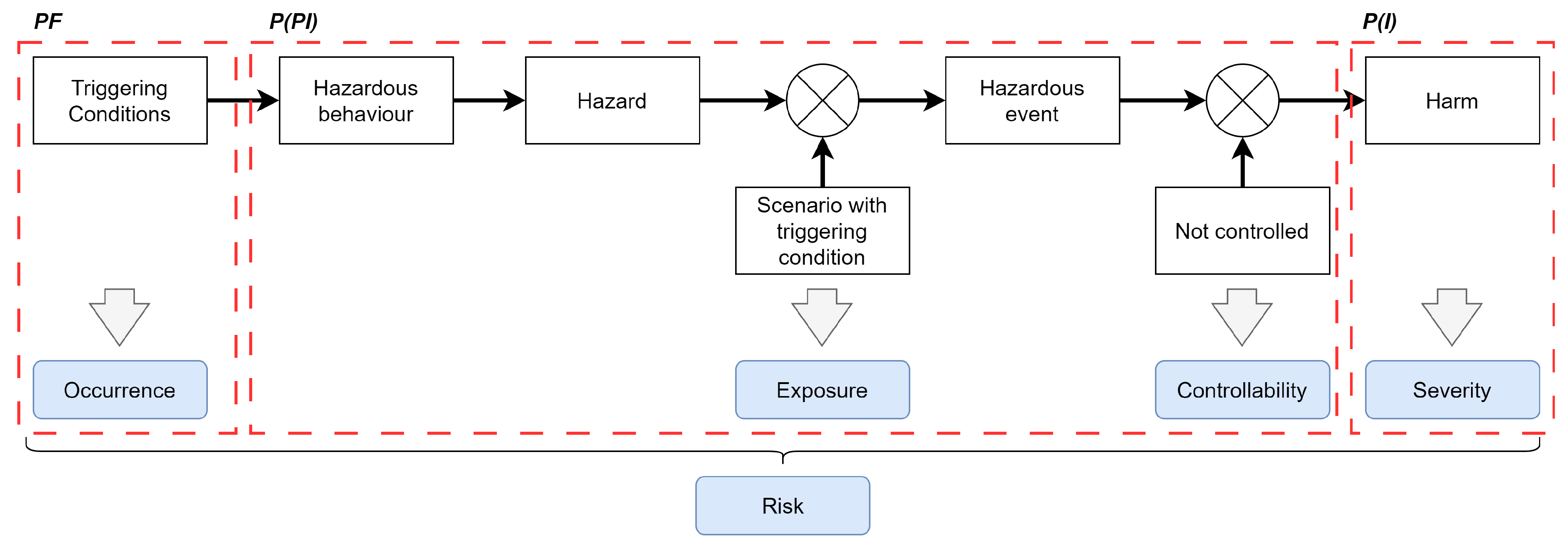
Figure 5. Risk quantification from our approach and compared with ISO21448.
Vehicles 06 00055 g005
Each variable is assigned a value ranging from 0 (mildest) to 4 (worst). The sum of these three variables (e.g., S 0 + C 2 + E 1 ) is used to determine the ASIL level. ASIL A is assigned to the lowest risk, while ASIL D is assigned to the highest risk. In contrast, ISO21448 [9] defines risk as the product of controllability and severity. Thus, the primary objective is to reduce controllability and severity to prevent harm or achieve the safety goal, considering a previously defined residual risk. In ideal scenarios, controllability and severity should be zero ( C = 0 or S = 0 ) to achieve optimal outcomes.
R i s k = P F P ( P I ) P ( I )
This approach calculates the risk based on Equation (5). This equation is based on two different probabilities. P ( P I ) represents the likelihood that a performance insufficiency may have an impact on the nominal performance of the system. This means that the results once the performance insufficiency is injected are outside a defined acceptable window. Nominal performance is calculated based on the values from Montecarlo simulations of the same scenario without the injection of any performance insufficiency. The tolerable window is calculated based on the standard deviation of this simulation and a given factor. As Figure 5 shows, if P ( P I ) is greater than zero, this implies that the ADS is susceptible to the injected insufficiency and it is also uncontrolled by ADS and, therefore, it is relevant for the system. On the other hand, P ( I ) is considered the probability of injury. It is assumed that both probabilities are independent for the sake of simplicity; however, dependent probabilities will be considered in further research to achieve more accurate quantification results. The probability of P ( I ) is determined using the methodology explained in [47,56]. The authors employ the model developed by Kusano and Gabler [57] to calculate the likelihood of injury. This model assesses the probability of injury as being greater when the injury level is equal to or greater than level 2 according to the Maximum Abbreviated Injury Scale (MAIS) [58]. MAIS level 2 is defined by moderate injuries with a low probability of death (1–2%). This value is considered in our approach as severity greater than zero ( S > 0 ) and, therefore, takes the risk into consideration. Otherwise, the probability of severity is zero as well as the risk. In this case, although the performance insufficiency still affects the system, SOTIF modifications may be applied in the ADS to enhance system reliability. The model [59] utilised to calculate the probability of injury is defined as follows:
P ( I ) = 1 1 + e ( β 0 + β 1 Δ v + β 2 ) MAIS 2 0 MAIS < 2
A Plausibility Factor ( P F ) was also added to the risk calculation to adjust the different levels of performance insufficiency injection. This factor decreases as the injection level becomes more extreme. For instance, if the system experiences reduced visibility, it is more plausible that visibility is not drastically reduced than that sensor visibility is almost lost. The plausibility coefficient has the same value as the probability of occurrence when a triggering condition is injected. However, it is not the same when a performance insufficiency is injected. Currently, the value of this factor is determined through expert judgement; however, further research will be conducted to calculate this factor accurately in the future. Finally, the equation that defines the risk for a performance insufficiency is given in Equation (7) for all levels of injection (S).
R i s k P I = i = 0 S P F i P ( P I i ) P ( I i ) 1 i S
Consequently, the risk evaluation of an ADS is obtained by summing all calculated risks for the considered performance insufficiencies (N), as shown in Equation (8).
R i s k A D S = i = 0 N R i s k P I j 1 j N
The risk calculated by this methodology provides a quantitative metric that must be evaluated by the stakeholder to determine if it is within the acceptance criteria for its SOTIF evaluation. The As Low As Reasonably Practicable (ALARP) [60] principle or similar should then be applied to reduce the risk to the lowest possible level. This also aligns with one of the main goals of SOTIF, according to which each validation iteration improves the system’s reliability and safety.

4. Use Case

This section presents two use cases to illustrate the proposed approach outlined in previous sections. In the first use case, the ADS is subjected to a limited visibility performance insufficiency by including a generic performance insufficiency with varying levels of intensity. In the second use case, the lack of accuracy is included in the system as a performance insufficiency, injecting different reflection levels. The environment simulator used was the open-source CARLA Simulator [61] in which all elements of the map were removed, leaving only the road and the vehicles (ego and target vehicles). The object detection of the ADS is based on the cluster detection from the Autoware [62] software stack. The ADS uses a lidar sensor located at the top of the vehicle as a unique perception sensor. The vehicle controller of the ADS was developed in ROS [63]. Figure 6 depicts the architecture for these use cases. It is assumed that the performance insufficiency injection does not introduce a significant delay into the system and that it does not affect the results. The scenario used is a deceleration scenario, where the ego vehicle (green) reduces speed or stops to avoid a collision with the target vehicle (red) located in front. The waypoint is straight without turning in any direction. The initial speed of the vehicles is zero with the maximum speed reached by the ego vehicle being 80 km/h. The deceleration scenario is shown in Figure 7. The top left picture shows the CARLA simulation; the top right shows the visualisation from the vehicles. A logical view is given below these pictures.
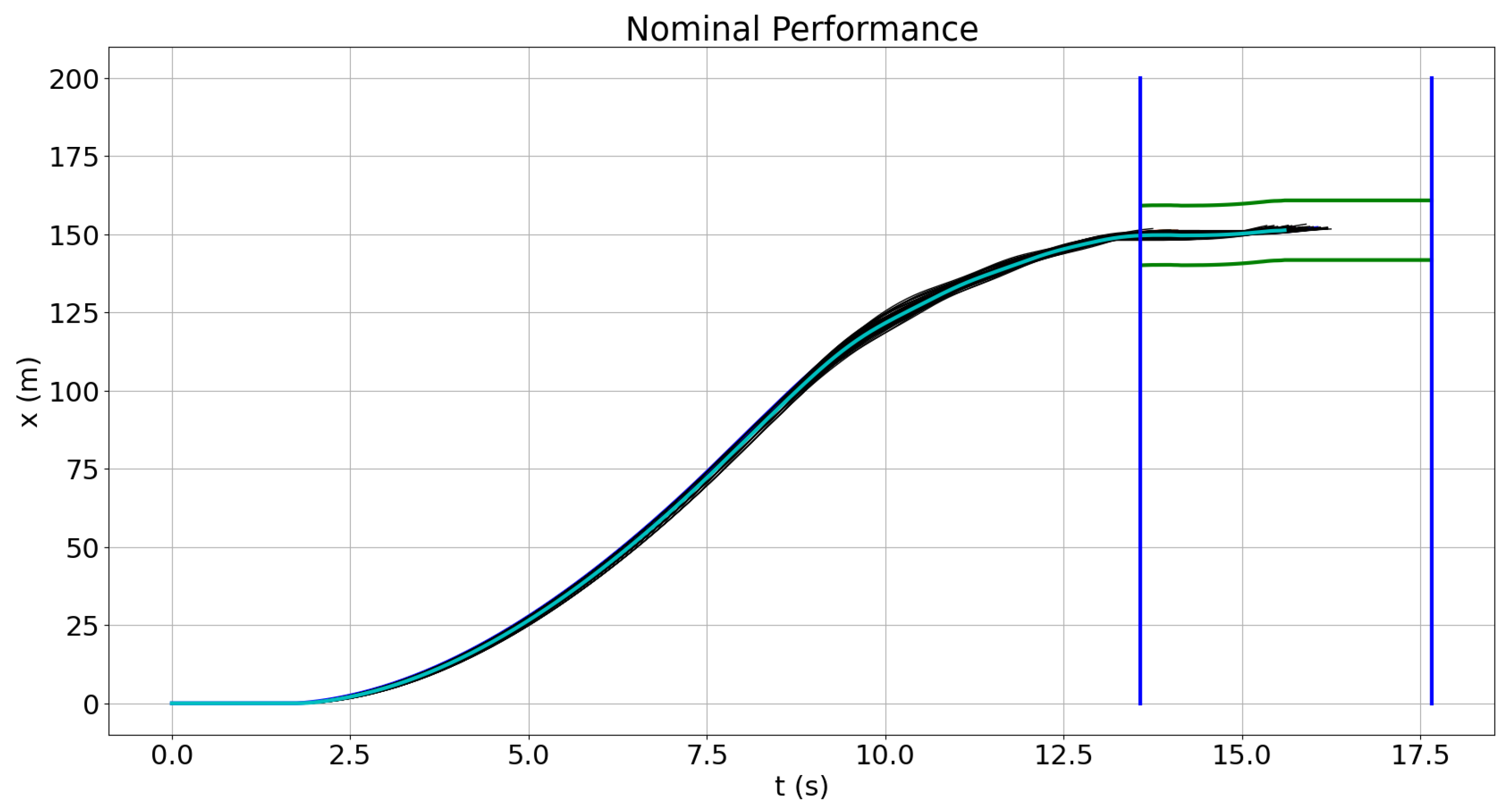
The nominal performance of the ADS is shown in Figure 8, where the distance travelled is plotted on the x-axis over time. Black lines show the performance of the ADS of each simulation with the mean value of the simulations also displayed with an overlapping cyan line. The execution time tolerable window is shown with vertical blue lines. Similarly, green lines are used to limit the tolerance window of the ADS distance travelled. The tolerable window is calculated based on the mean value from the nominal performance simulations in which the standard deviation is multiplied by a factor set to the upper and lower limits. In this use case, one hundred simulations ( B = 100 ) were performed to obtain the probabilistic values. Whether execution time or distance travelled is outside the defined tolerance window, this is considered hazardous behaviour.

4.1. Performance Insufficiencies Injection

The initial aim is to translate the generic performance insufficiency into a technological performance insufficiency. Since the perception sensor in this ADS is a lidar, the reduction of the field of view has been modelled as the cropping of the point cloud generated from the lidar sensor. In order to increase the performance of the simulations and reduce the test cases, only the Responsibility-Sensitive Safety (RSS) [52] area ( A R S S ) is considered in the tests. This decision was made because, based on the model, only this area is relevant for the safety of the vehicle. In our approach, the velocity of the target vehicle was set to zero in the original RSS equation to be more conservative.
D R S S = v r ρ + 1 2 a m a x , a c c e l ρ 2 + ( v r + ρ a m a x , a c c e l ) 2 2 a m i n , b r a k e + [ x ] + : = m a x { x , 0 }
The meaning and the given value for each parameter of the formula are outlined below:
  • DRSS: Minimum distance to ensure that there is no crash with the obstacle.
  • vr: Max ego vehicle velocity (m/s) in the test scenario. Value: 22.22 m/s (80 km/h).
  • ρ: Response time in seconds: 0.5 s.
  • amax,accel: Maximum acceleration of the robot (m/s2). Value: 5.5 m/s2.
  • amin,brake: Minimum braking acceleration of the robot (m/s2). Value: 4.5 m/s2.
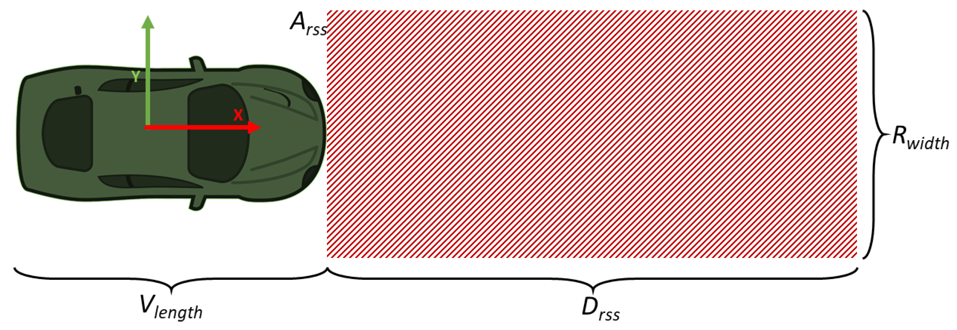
The minimum distance is only used for the longitude value; for the latitude value, the standard width for a highway is applied instead, 3.75 m [64]. The RSS distance, calculated using the given values, is 81.09 m (DRSS). Vehicle length is assumed to be five metres. The area ( A R S S ) considered for analysis is depicted in Figure 9 and can be described as follows:
V l e n g t h / 2 < X < V l e n g t h / 2 + D R S S R w i d t h / 2 < Y < R w i d t h / 2
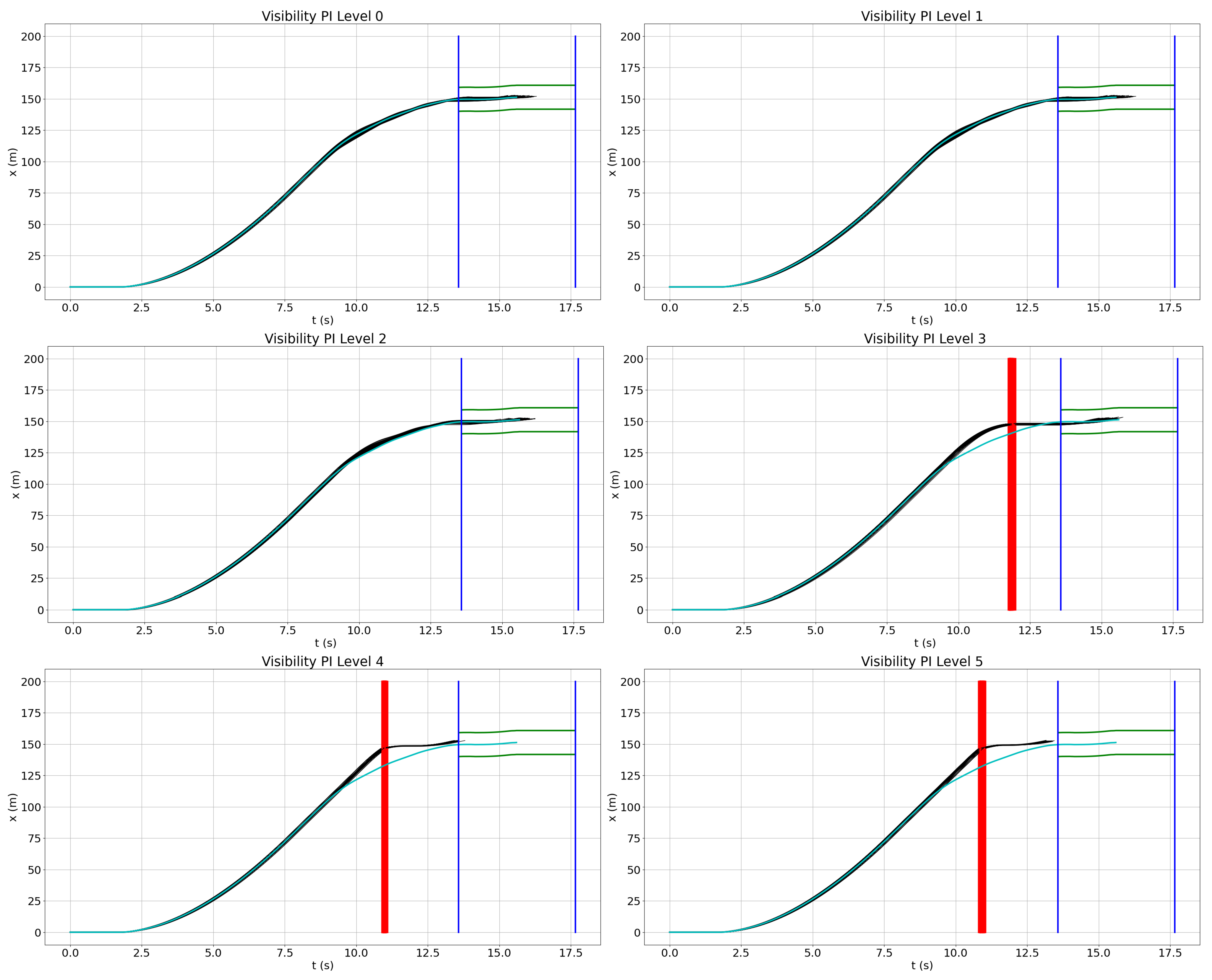
The reduced visibility levels for the limited visibility performance insufficiency injected into the system are 80, 60, 45, 30, 20 and 15 m. Figure 10 shows the results of these injections. In this use case, level 0 (80 m), level 1 (60 m) and level 2 (45 m) do not have any impact on the output of the ADS. From level 3 (30 m) on, the injections do have an impact on the system, resulting in collisions. At these levels, the difference between nominal performance (cyan line) and the output with the injection is clear, with collisions shown as vertical red lines. Collisions occur earlier in each injection, since detection of the target is delayed due to visibility insufficiency, leading to delayed braking and, finally, a collision. Table 3 shows the probabilities of hazardous behaviour and collision of each injection level. In this case, all hazardous behaviours lead to a collision, although this behaviour does not always occur. As shown in the charts, the impact of the performance insufficiency starts to be relevant at level 3. At this level, two thirds of all simulations are outside of the tolerance windows and lead to a collision. Then, the injections have a full impact on the outcome of the ADS. These results follow the cause and effect model shown in Figure 1, where the visibility reduction injected at the technical level leads to an output insufficiency at the functional level. There is a late detection from the sensor block that generates a lag on the actuation block, followed by a late braking at the vehicle level, which ends in hazardous behaviour.

4.2. Field of View Reduction

Quantitative Risk Evaluation

As previously described in Section 3, the risk depends on the Plausibility Factor ( P F ), the probability of performance insufficiency ( P ( P I ) ), and the probability of injury ( P ( I ) ). The Plausibility Factor was calculated based on the values from an exponential distribution with a given lambda value ( λ = 1) and a random variable (X) set by expertise judgement for each level. The plausibility values for this use case for all levels are shown in Table 4.
Based on the risk calculation given in Section 3, the following equation shows the evaluated risk for the lowest level of the reduced visibility performance level. The Plausibility Factor for this injection is the maximum, P F v i s 80 = 1.0000 , because it could occur with a high probability in many scenarios: if this happens, its impact must not be minimised. The probability of performance insufficiency is zero, which is expected since the reduced visibility is close to the nominal field of view of the sensor. The probability of injury is also zero, since there are no collisions. Consequently, the risk for this performance insufficiency level is zero, as shown in Equation (11).
R i s k v i s 80 = P F v i s 80 P ( P I v i s 180 ) P ( I v i s 80 ) = 1.00 0.00 0.00 = 0.00
Unlike the risk evaluation previously calculated, the risk for level 3 of injection ( R i s k v i s 30 ) is not zero. In this case, the given Plausibility Factor is more restrictive, as this kind of performance insufficiency level does not occur as regularly. The probability of this injection level is not zero, and it has an impact on two thirds of the simulations. The probability of injury is not zero, since there are collisions that could cause moderate injuries to drivers.
R i s k v i s 30 = 0.04979 0.66 1.22966 × 10 2
As expected, the values of the probability of injury increase when stricter levels are injected because there is less time for the vehicle to brake, and thus the crash velocity is higher for each level. On the other hand, the overall risk for each level is not always higher than the previous level because of the given Plausibility Factor. Finally, the quantitative risk evaluation for this reduced visibility performance insufficiency based on the results from Table 5 is as follows:
R i s k P I v i s = R i s k v i s 80 + R i s k v i s 60 + R i s k v i s 45 + R i s k v i s 30 + R i s k v i s 20 + R i s k v i s 15 = 1.36557 × 10 3
This quantitative risk evaluation provides a reference point for the minimisation of risk in subsequent iterations of the SOTIF validation. It is noted that these results could be used to validate the function for specific triggering conditions defined in the standards. For instance, the SAE standard [20] classifies fog into six levels based on system visibility.
  • Level 5: 0 m ≤ visibility < 61 m
  • Level 4: 61 m ≤ visibility < 244 m
  • Level 3: 244 m ≤ visibility < 805 m
  • Level 2: 805 m ≤ visibility < 1609 m
  • Level 1: visibility ≥ 1609 m
Therefore, the system is validated for the SAE fog scale up to level 4 (visibility > 60 m), ensuring zero risk at those levels in the system:
R i s k P I v i s S A E L e v e l 4 = R i s k v i s 60 = 0.00

4.3. Accuracy Reduction

A reduction in the accuracy of the perception component is included in the system based on the classification from Table 1 in this use case. The primary objective of this use case is to demonstrate how reflections at different density levels can affect the system’s object detection and resulting behaviour.

4.3.1. Performance Insufficiencies Injection

Table 2 shows how this performance insufficiency is modelled for lidar-specific technology in which random points are injected into the point cloud from the message. Similar to the first use case, only the area ( A R S S ) from the RSS is considered because it is the relevant safety area for the test case. Different levels of point density are injected in the system, where density is calculated based on the number of points in the A R S S based on sensor resolution and the number of injected points for this area ( i n j e c t i o n _ d e n s i t y = n u m b e r _ i n j e c t e d _ p o i n t s / n u m b e r _ A R S S _ p o i n t s ).
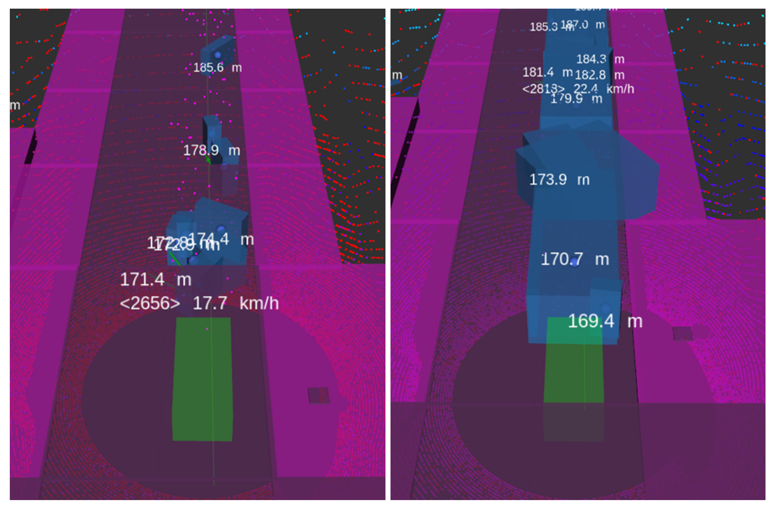
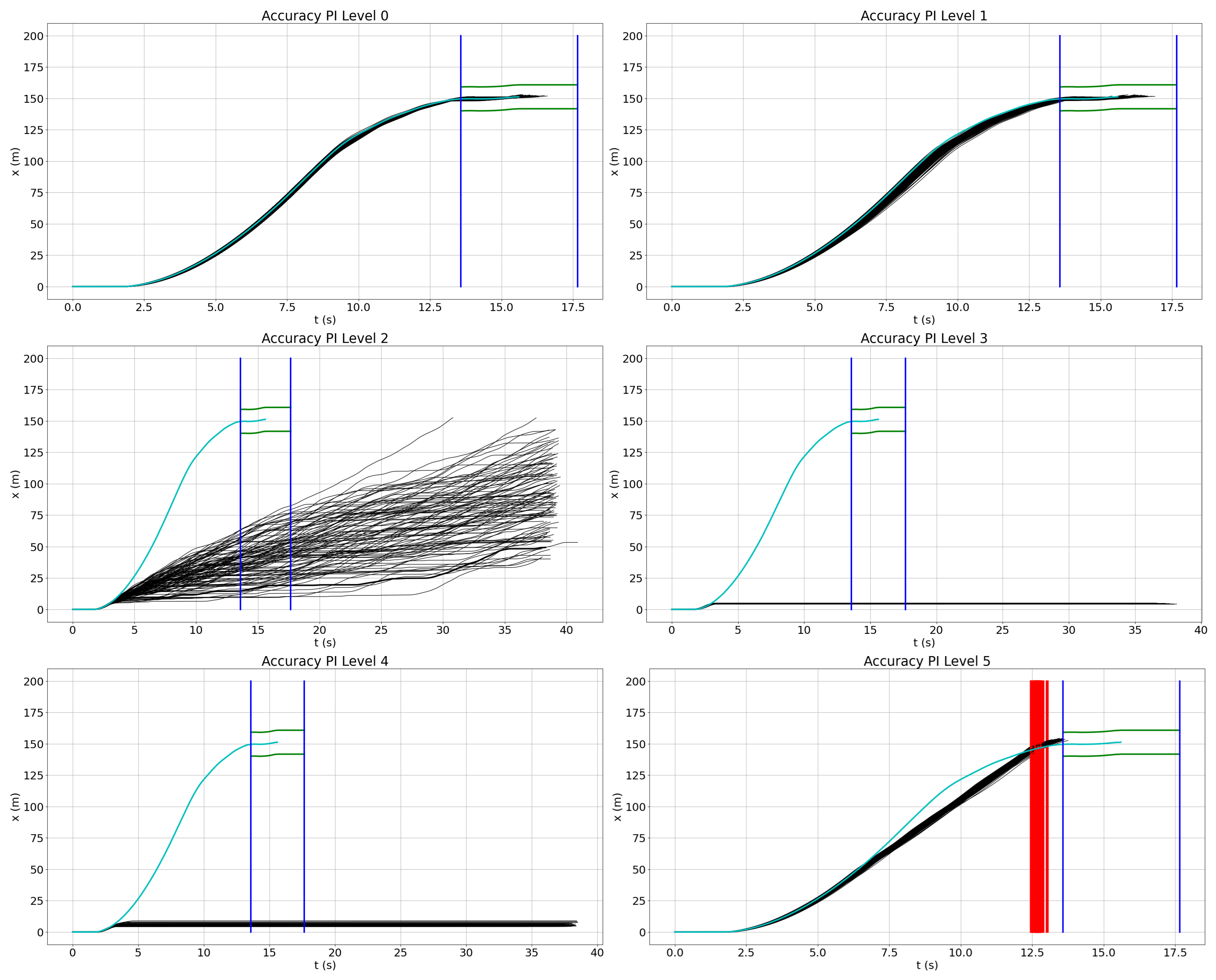
Figure 11 shows two levels of injection from the vehicle perspective. The left picture shows level 2 of injection, where we observe the false negatives produced by the random reflections in the point cloud message. The right picture shows a higher level of injection, where the amount of false detections makes the ego vehicle stop completely. The impact of each injection level is shown in Figure 12. Levels 0 and 1 do not have any relevant impact on the outcome of the function, but from level 3, the impact of the outcome is remarkable. Level 2 makes the ADS still follow the path but with successive stops due to the false negatives, while at levels 3 and 4, the ego vehicle remains stopped. Noteworthy is level 5, where the huge amount of reflections causes the target vehicle not to be considered as an object, eventually leading to a collision. Unlike the previous use case, in this case, hazardous behaviour does not always generate a collision, as Table 6 depicts.
Table 6 displays the results of the injections. It is noteworthy that although this injection has an impact on the system at many levels, the included reflections do not affect the system at levels 0 to 2. However, levels 3 and 4 include false positives due to the injected reflections, which activate the braking system and prevent the vehicle from following the defined path. On the other hand, all hazardous behaviours lead to a collision at the most restrictive level of injection.

4.3.2. Quantitative Risk Evaluation

After calculating the probability of performance insufficiency, the risk can be evaluated. As with the previous use case, the Plausibility Factor was determined using an exponential distribution and values based on expert judgement. Table 7 displays the risk values for each level with only the final level posing a risk in the ADS due to the occurrence of collisions. It is important to note that there are many injections where the performance insufficiency has an impact on the behaviour of the system, but there are no collisions. Despite this, SOTIF measures should be implemented to minimise the probability of hazardous behaviours. For example, including a wide range of perception sensor technologies could be beneficial as each sensor technology has its advantages and disadvantages in specific environmental situations, which could help mitigate the impact of certain scenarios.
The equation below shows the calculated risk for the reduction of accuracy, where only the last injection has an impact on the final risk quantification for this performance insufficiency; even though most of the performance insufficiency injections have an impact on the system output, only the last injection has an impact on the risk quantification. The aim is to indicate that both risk and SOTIF modifications are relevant in the validation process.
R i s k A D S = i = 0 5 R i s k P I j = 8.54309 × 10 5 0 j 5

5. Conclusions and Future Work

This document describes a methodology for validating perception performance insufficiencies in automotive driving systems. Due to the impossibility of validating all possible triggering conditions of a scenario, the evaluation focuses on the impact of performance insufficiencies in the perception component of the system and its effect on the output of the entire system in order to determine whether it may lead to hazardous behaviour and, finally, possibly cause harm. In the document, a classification of the performance insufficiencies is given, showing the impact of the defined insufficiency in the system. Then, a model for each perception insufficiency is used to inject the insufficiency into the system and determine whether the specified performance insufficiency does have an impact on the ADS output. Based on the results from the injections, a Plausibility Factor and a probability of injury are calculated; when the injection leads to a collision, a quantitative risk could be calculated. Since the risk is based on the severity of injuries, if there are no collisions or the injuries caused by a collision are light, the risk is set to zero. In these situations, SOTIF measurement should be considered to minimise the probability of performance insufficiency. The calculated risk provides us with a quantitative metric that serves as a reference for improvement in further validation iterations. Finally, this text describes two use cases that show how the proposed methodology can be applied. The first use case validates a limited visibility performance insufficiency in which most of the hazardous behaviours lead to risk due to collisions. The second use case validates a reduction in accuracy, where most levels of injection do not result in a collision, indicating no risk, but they still have an impact on the system. Therefore, SOTIF measures should still be applied to improve the ADS against this type of performance insufficiency.
This research has raised several questions that require further investigation. Although the risk evaluation provides a quantitative metric, it is not related to any specific measure, such as the number of hours driven or kilometres travelled. Future research should address this issue to better link the obtained metric with real-world measurements. Another important question that needs to be addressed is how to determine when a performance insufficiency has been fully validated, including accurate models for each performance insufficiency. Additionally, a more effective approach to identifying edge cases in performance insufficiency injection testing should be implemented in the future.

Author Contributions

Conceptualization, V.J.E.J.; Methodology, V.J.E.J.; Software, V.J.E.J.; Validation, V.J.E.J.; Formal analysis, V.J.E.J.; Investigation, V.J.E.J.; Resources, V.J.E.J.; Data curation, V.J.E.J.; Writing—original draft, V.J.E.J.; Writing—review and editing, D.W., G.M. and E.B.; Visualization, V.J.E.J.; Supervision, G.M. and E.B. All authors have read and agreed to the published version of the manuscript.

Funding

Open Access Funding by the Graz University of Technology.

Data Availability Statement

Data are contained within the article. The original contributions presented in the study are included in the article, further inquiries can be directed to the corresponding authors.

Acknowledgments

The publication was written at Virtual Vehicle Research GmbH in Graz, Austria. The authors would like to acknowledge the financial support within the COMET K2 Competence Centers for Excellent Technologies from the Austrian Federal Ministry for Climate Action (BMK), the Austrian Federal Ministry for Labour and Economy (BMAW), the Province of Styria (Dept. 12) and the Styrian Business Promotion Agency (SFG). The Austrian Research Promotion Agency (FFG) has been authorised for the programme management. Supported by TU Graz Open Access Publishing Fund.

Conflicts of Interest

Author Víctor J. Expósito Jiménez and Daniel Watzenig were employed by the company Virtual Vehicle Research GmbH. The remaining authors declare that the research was conducted in the absence of any commercial or financial relationships that could be construed as a potential conflict of interest.

Abbreviations

The following abbreviations are used in this manuscript:
ADASAdvanced Driver-Assistance System
ADSAutomated Driving System
ALARPAs Low As Reasonably Practicable
ASILAutomotive Safety Integrity Level
GPIGeneric Performance Insufficiency
HARAHazard Analysis and Risk Assessment
HILHardware-In-Loop
KPIKey Performance Indicator
MDPIMultidisciplinary Digital Publishing Institute
ODDOperational Design Domain
PFPlausibility Factor
PIPerformance Insufficiency
RSSResponsibility-Sensitive Safety
SOTIF  Safety Of The Intended Functionality
SPISafety Performance Indicator
TCPITriggering Condition Performance Insufficiency
TPITechnology Performance Insufficiency

References

  1. (EU) 2022/1426; Commission Implementing Regulation (EU) 2022/1426—Commision Implementing Act AD v4.1. European Commission: Brussel, Belgium, 2022.
  2. National Transportation Safety Board (NTSB). Collision between a Sport Utility Vehicle Operating with Partial Driving Automation and a Crash Attenuator, Mountain View, California, March 23, 2018. 2020. Available online: https://www.ntsb.gov/investigations/AccidentReports/Reports/HAR2001.pdf (accessed on 12 May 2023).
  3. Bonnefon, J.F. 18 The Uber Accident. In The Car That Knew Too Much: Can a Machine Be Moral? The MIT Press: Cambridge, MA, USA, 2021; pp. 93–98. [Google Scholar]
  4. Shah, S.A. Safe-AV: A Fault Tolerant Safety Architecture for Autonomous Vehicles. Ph.D. Thesis, McMaster University, Hamilton, ON, USA, 2019. [Google Scholar]
  5. AI Incident Database. Incident 293: Cruise’s Self-Driving Car Involved in a Multiple-Injury Collision at an San Francisco Intersection. 2022. Available online: https://incidentdatabase.ai/cite/293/ (accessed on 3 March 2024).
  6. Ballingall, S.; Sarvi, M.; Sweatman, P. Standards relevant to automated driving system safety: A systematic assessment. Transp. Eng. 2023, 13, 100202. [Google Scholar] [CrossRef]
  7. Koopman, P. How Safe Is Safe Enough?: Measuring and Predicting Autonomous Vehicle Safety; Amazon Digital Services LLC: Seattle, WA, USA, 2022. [Google Scholar]
  8. UL4600; Standard for Safety: Evaluation of Autonomous Products. Standards and Engagement Inc.: Evanston, IL, USA, 2021.
  9. ISO 21448:2022; Road vehicles—Safety of the Intended Functionality. International Organization for Standardization: Geneva, Switzerland, 2022.
  10. Westhofen, L.; Neurohr, C.; Koopmann, T.; Butz, M.; Schütt, B.; Utesch, F.; Neurohr, B.; Gutenkunst, C.; Böde, E. Criticality Metrics for Automated Driving: A Review and Suitability Analysis of the State of the Art. Arch. Comput. Methods Eng. 2022, 30, 1–35. [Google Scholar] [CrossRef]
  11. Sun, C.; Zhang, R.; Lu, Y.; Cui, Y.; Deng, Z.; Cao, D.; Khajepour, A. Toward Ensuring Safety for Autonomous Driving Perception: Standardization Progress, Research Advances, and Perspectives. IEEE Trans. Intell. Transp. Syst. 2023, 25, 3286–3304. [Google Scholar] [CrossRef]
  12. Wang, H.; Shao, W.; Sun, C.; Yang, K.; Cao, D.; Li, J. A Survey on an Emerging Safety Challenge for Autonomous Vehicles: Safety of the Intended Functionality. Engineering 2024, 33, 17–34. [Google Scholar] [CrossRef]
  13. Hoss, M.; Scholtes, M.; Eckstein, L. A Review of Testing Object-Based Environment Perception for Safe Automated Driving. Automot. Innov. 2022, 5, 223–250. [Google Scholar] [CrossRef]
  14. Zhu, Z.; Philipp, R.; Hungar, C.; Howar, F. Systematization and Identification of Triggering Conditions: A Preliminary Step for Efficient Testing of Autonomous Vehicles. In Proceedings of the 2022 IEEE Intelligent Vehicles Symposium (IV), Aachen, Germany, 4–9 June 2022; pp. 798–805. [Google Scholar] [CrossRef]
  15. Expósito Jiménez, V.J.; Martin, H.; Schwarzl, C.; Macher, G.; Brenner, E. Triggering Conditions Analysis and Use Case for Validation of ADAS/ADS Functions. In International Conference on Computer Safety, Reliability, and Security; SAFECOMP 2022 Workshops; Trapp, M., Schoitsch, E., Guiochet, J., Bitsch, F., Eds.; Springer: Cham, Switzerland, 2022; pp. 11–22. [Google Scholar]
  16. ISO 26262:2018; Road Vehicles—Functional Safety. International Organization for Standardization: Geneva, Switzerland, 2018.
  17. Koopman, P.; Kane, A.; Black, J. Credible Autonomy Safety Argumentation. In Proceedings of the 27th Safety-Critical Systems Symposium 2019, Bristol, UK, 5–7 February 2019. [Google Scholar]
  18. United Nations Economic Commission for Europe (UNECE). New Assessment/Test Method for Automated Driving (NATM)—Master Document (Final Draft). 2021. Available online: https://unece.org/sites/default/files/2021-01/GRVA-09-07e.pdf (accessed on 9 February 2024).
  19. ISO/DIS 34505; Road Vehicles—Test Scenarios for Automated Driving Systems—Scenario Based Safety Evaluation Framework. International Organization for Standardization: Geneva, Switzerland, 2022.
  20. AVSC00002202004; AVSC Best Practice for Describing an Operational Design Domain: Conceptual Framework and Lexicon. Society of Automotive Engineers (SAE) International: Pittsburgh, PA, USA, 2020.
  21. BSI PAS 1883:2020; Operational Design Domain (ODD) Taxonomy for an Automated Driving System (ADS). Specification. The British Standards Institution: London, UK, 2020.
  22. Weissensteiner, P.; Stettinger, G.; Khastgir, S.; Watzenig, D. Operational Design Domain-Driven Coverage for the Safety Argumentation of Automated Vehicles. IEEE Access 2023, 11, 12263–12284. [Google Scholar] [CrossRef]
  23. Weissensteiner, P.; Stettinger, G.; Rumetshofer, J.; Watzenig, D. Virtual Validation of an Automated Lane-Keeping System with an Extended Operational Design Domain. Electronics 2022, 11, 72. [Google Scholar] [CrossRef]
  24. Scholtes, M.; Westhofen, L.; Turner, L.R.; Lotto, K.; Schuldes, M.; Weber, H.; Wagener, N.; Neurohr, C.; Bollmann, M.H.; Körtke, F.; et al. 6-Layer Model for a Structured Description and Categorization of Urban Traffic and Environment. IEEE Access 2021, 9, 59131–59147. [Google Scholar] [CrossRef]
  25. ASAM e.V. ASAM OpenODD. 2021. Available online: https://www.asam.net/project-detail/asam-openodd/ (accessed on 5 December 2023).
  26. Virtual Vehicle Research GmbH. SPIDER: Mobile Platform for the Development and Testing of Autnomous Driving Functions. 2021. Available online: https://www.v2c2.at/spider/ (accessed on 5 December 2023).
  27. AVL List GmbH. AVL DRIVINGCUBE. 2023. Available online: https://www.avl.com/en/testing-solutions/automated-and-connected-mobility-testing/avl-drivingcube (accessed on 7 February 2024).
  28. de Gelder, E.; Paardekooper, J.P.; Op den Camp, O.; De Schutter, B. Safety assessment of automated vehicles: How to determine whether we have collected enough field data? Traffic Inj. Prev. 2019, 20, S162–S170. [Google Scholar] [CrossRef]
  29. Linnhoff, C.; Hofrichter, K.; Elster, L.; Rosenberger, P.; Winner, H. Measuring the Influence of Environmental Conditions on Automotive Lidar Sensors. Sensors 2022, 22, 5266. [Google Scholar] [CrossRef]
  30. Fang, J.; Zhou, D.; Zhao, J.; Tang, C.; Xu, C.Z.; Zhang, L. LiDAR-CS Dataset: LiDAR Point Cloud Dataset with Cross-Sensors for 3D Object Detection. arXiv 2023, arXiv:cs.CV/2301.12515. [Google Scholar]
  31. Schlager, B.; Muckenhuber, S.; Schmidt, S.; Holzer, H.; Rott, R.; Maier, F.M.; Saad, K.; Kirchengast, M.; Stettinger, G.; Watzenig, D.; et al. State-of-the-Art Sensor Models for Virtual Testing of Advanced Driver Assistance Systems/Autonomous Driving Functions. SAE Int. J. Connect. Autom. Veh. 2020, 3, 233–261. [Google Scholar] [CrossRef]
  32. Bijelic, M.; Gruber, T.; Mannan, F.; Kraus, F.; Ritter, W.; Dietmayer, K.; Heide, F. Seeing Through Fog Without Seeing Fog: Deep Multimodal Sensor Fusion in Unseen Adverse Weather. In Proceedings of the 2020 IEEE/CVF Conference on Computer Vision and Pattern Recognition (CVPR), Seattle, WA, USA, 13–19 June 2020; pp. 11679–11689. [Google Scholar] [CrossRef]
  33. Dreissig, M.; Scheuble, D.; Piewak, F.; Boedecker, J. Survey on LiDAR Perception in Adverse Weather Conditions. arXiv 2023, arXiv:cs.RO/2304.06312. [Google Scholar]
  34. Minh Mai, N.A.; Duthon, P.; Salmane, P.H.; Khoudour, L.; Crouzil, A.; Velastin, S.A. Camera and LiDAR analysis for 3D object detection in foggy weather conditions. In Proceedings of the 2022 12th International Conference on Pattern Recognition Systems (ICPRS), Etienne, France, 7–10 June 2022; pp. 1–7. [Google Scholar] [CrossRef]
  35. Hahner, M.; Sakaridis, C.; Dai, D.; Van Gool, L. Fog Simulation on Real LiDAR Point Clouds for 3D Object Detection in Adverse Weather. In Proceedings of the IEEE International Conference on Computer Vision (ICCV), Montreal, BC, Canada, 11–17 October 2021. [Google Scholar]
  36. Hahner, M.; Sakaridis, C.; Bijelic, M.; Heide, F.; Yu, F.; Dai, D.; Van Gool, L. LiDAR Snowfall Simulation for Robust 3D Object Detection. In Proceedings of the 2022 IEEE/CVF Conference on Computer Vision and Pattern Recognition (CVPR), New Orleans, LA, US, 18–24 June 2022; pp. 16343–16353. [Google Scholar] [CrossRef]
  37. Skender, I. Robustness Test for ADAS Function. Master’s Thesis, Graz University of Technology, Graz, Austria, 2022. [Google Scholar]
  38. Pizzati, F.; Cerri, P.; de Charette, R. Model-Based Occlusion Disentanglement for Image-to-Image Translation. In Proceedings of the Computer Vision—ECCV 2020; Vedaldi, A., Bischof, H., Brox, T., Frahm, J.M., Eds.; Springer: Cham, Switzerland, 2020; pp. 447–463. [Google Scholar]
  39. Sadeghi, J.; Rogers, B.; Gunn, J.; Saunders, T.; Samangooei, S.; Dokania, P.K.; Redford, J. A Step Towards Efficient Evaluation of Complex Perception Tasks in Simulation. arXiv 2021, arXiv:cs.LG/2110.02739. [Google Scholar]
  40. Piazzoni, A. Modeling Perception Errors in Autonomous Vehicles and Their Impact on Behavior; Nanyang Technological University: Nanyang, China, 2023. [Google Scholar] [CrossRef]
  41. Piazzoni, A.; Cherian, J.; Slavik, M.; Dauwels, J. Modeling perception errors towards robust decision making in autonomous vehicles. In Proceedings of the IJCAI’20: Twenty-Ninth International Joint Conference on Artificial Intelligence, Yokohama, Japan, 11–17 July 2021. [Google Scholar]
  42. Piazzoni, A.; Cherian, J.; Dauwels, J.; Chau, L.P. PEM: Perception Error Model for Virtual Testing of Autonomous Vehicles. IEEE Trans. Intell. Transp. Syst. 2024, 25, 670–681. [Google Scholar] [CrossRef]
  43. Szegedy, C.; Zaremba, W.; Sutskever, I.; Bruna, J.; Erhan, D.; Goodfellow, I.; Fergus, R. Intriguing properties of neural networks. arXiv 2014, arXiv:cs.CV/1312.6199. [Google Scholar]
  44. Sadeghi, J.; Lord, N.A.; Redford, J.; Mueller, R. Attacking Motion Planners Using Adversarial Perception Errors. arXiv 2023, arXiv:cs.RO/2311.12722. [Google Scholar]
  45. Innes, C.; Ramamoorthy, S. Testing Rare Downstream Safety Violations via Upstream Adaptive Sampling of Perception Error Models. In Proceedings of the 2023 IEEE International Conference on Robotics and Automation (ICRA), London, UK, 29 May –2 June 2023 2023; pp. 12744–12750. [Google Scholar] [CrossRef]
  46. Putze, L.; Westhofen, L.; Koopmann, T.; Böde, E.; Neurohr, C. On Quantification for SOTIF Validation of Automated Driving Systems. In Proceedings of the 2023 IEEE Intelligent Vehicles Symposium (IV), Anchorage, AK, USA, 4–7 June 2023; pp. 1–8. [Google Scholar] [CrossRef]
  47. de Gelder, E.; Elrofai, H.; Saberi, A.K.; Paardekooper, J.P.; Op den Camp, O.; de Schutter, B. Risk Quantification for Automated Driving Systems in Real-World Driving Scenarios. IEEE Access 2021, 9, 168953–168970. [Google Scholar] [CrossRef]
  48. Kramer, B.; Neurohr, C.; Büker, M.; Böde, E.; Fränzle, M.; Damm, W. Identification and Quantification of Hazardous Scenarios for Automated Driving. In International Symposium on Model-Based Safety and Assessment; Zeller, M., Höfig, K., Eds.; Springer: Cham, Switzerland, 2020; pp. 163–178. [Google Scholar]
  49. Vaicenavicius, J.; Wiklund, T.; Grigaite, A.; Kalkauskas, A.; Vysniauskas, I.; Keen, S.D. Self-Driving Car Safety Quantification via Component-Level Analysis. SAE Int. J. Connect. Autom. Veh. 2021, 4, 35–45. [Google Scholar] [CrossRef]
  50. Karunakaran, D.; Worrall, S.; Nebot, E.M. Efficient Statistical Validation with Edge Cases to Evaluate Highly Automated Vehicles. In Proceedings of the 2020 IEEE 23rd International Conference on Intelligent Transportation Systems (ITSC), Rhodes, Greece, 20–23 September 2020; pp. 1–8. [Google Scholar]
  51. Chu, J.; Zhao, T.; Jiao, J.; Yuan, Y.; Jing, Y. SOTIF-Oriented Perception Evaluation Method for Forward Obstacle Detection of Autonomous Vehicles. IEEE Syst. J. 2023, 17, 2319–2330. [Google Scholar] [CrossRef]
  52. Shalev-Shwartz, S.; Shammah, S.; Shashua, A. On a Formal Model of Safe and Scalable Self-driving Cars. arXiv 2017, arXiv:1708.06374. [Google Scholar]
  53. Peng, L.; Li, B.; Yu, W.; Yang, K.; Shao, W.; Wang, H. SOTIF Entropy: Online SOTIF Risk Quantification and Mitigation for Autonomous Driving. IEEE Trans. Intell. Transp. Syst. 2024, 25, 1530–1546. [Google Scholar] [CrossRef]
  54. ISO/SAE PAS 22736:2021; Taxonomy and Definitions for Terms Related to Driving Automation Systems for On-Road Motor Vehicles. Society of Automotive Engineers (SAE) International: Pittsburgh, PA, USA, 2021.
  55. Expósito Jiménez, V.J.; Winkler, B.; Castella Triginer, J.M.; Scharke, H.; Schneider, H.; Brenner, E.; Macher, G. Safety of the Intended Functionality Concept Integration into a Validation Tool Suite. Ada User J. 2023, 44, 244–447. [Google Scholar] [CrossRef]
  56. Zhao, D.; Huang, X.; Peng, H.; Lam, H.; LeBlanc, D.J. Accelerated Evaluation of Automated Vehicles in Car-Following Maneuvers. IEEE Trans. Intell. Transp. Syst. 2018, 19, 733–744. [Google Scholar] [CrossRef]
  57. Kusano, K.D.; Gabler, H.C. Potential Occupant Injury Reduction in Pre-Crash System Equipped Vehicles in the Striking Vehicle of Rear-end Crashes. In Annals of Advances in Automotive Medicine; Annual Scientific Conference; Association for the Advancement of Automotive Medicine: Chicago, IL, USA, 2010; Volume 54, pp. 203–214. [Google Scholar]
  58. Gennarelli, T.A.; Wodzin, E. AIS 2005: A contemporary injury scale. Injury 2006, 37, 1083–1091. [Google Scholar] [CrossRef]
  59. Kusano, K.D.; Gabler, H.C. Safety Benefits of Forward Collision Warning, Brake Assist, and Autonomous Braking Systems in Rear-End Collisions. IEEE Trans. Intell. Transp. Syst. 2012, 13, 1546–1555. [Google Scholar] [CrossRef]
  60. EN50126-2; Railway Applications—The Specification and Demonstration of Reliability, Availability, Maintainability and Safety (RAMS) Part 2: Systems Approach to Safety. CENELEC—European Committee for Electrotechnical Standardization: Brussel, Belgium, 2017.
  61. Dosovitskiy, A.; Ros, G.; Codevilla, F.; Lopez, A.; Koltun, V. CARLA: An Open Urban Driving Simulator. In Proceedings of the 1st Annual Conference on Robot Learning, Mountain View, CA, USA, 13–15 November 2017; pp. 1–16. [Google Scholar]
  62. The Autoware Foundation. Autoware. 2021. Available online: https://www.autoware.org/autoware (accessed on 3 May 2023).
  63. Open Source Robotics Foundation, Inc. ROS—Robot Operating System. 2023. Available online: https://www.ros.org/ (accessed on 3 May 2023).
  64. European Road Safety Observation—European Commission. Motorways 2018. 2018. Available online: https://road-safety.transport.ec.europa.eu/system/files/2021-07/ersosynthesis2018-motorways.pdf (accessed on 7 September 2023).
Figure 1. Cause and effect model between potential functional insufficiencies and triggering conditions.
Vehicles 06 00055 g001
Figure 2. Evolution of the scenario categories through the SOTIF validation iterations.
Vehicles 06 00055 g002
Figure 3. Sense—Plan—Act Model.
Vehicles 06 00055 g003
Figure 4. Architecture of the injection approach.
Vehicles 06 00055 g004
Figure 6. Use cases architecture.
Vehicles 06 00055 g006
Figure 7. Deceleration Scenario. Up-left: CARLA visualisation. Up-right: vehicle visualisation. Down: logical view.
Vehicles 06 00055 g007
Figure 8. Nominal performance results.
Vehicles 06 00055 g008
Figure 9. Considered RSS area in the test cases.
Vehicles 06 00055 g009
Figure 10. Results of the visibility performance insufficiency injections.
Vehicles 06 00055 g010
Figure 11. Reduced accuracy performance insufficiency simulation.
Vehicles 06 00055 g011
Figure 12. Results of the accuracy performance insufficiency use case.
Vehicles 06 00055 g012
Table 1. Generic performance insufficiencies excerpt list.
GPI IDGeneric Performance Insufficiency (GPI)Impact
PI-01Reduction of Field of View (FoV)The visual range of the sensor is reduced from the nominal sensor performance.
PI-02Light disturbanceAn external light source affects the sensor perception.
PI-03MisalignmentThe position of the sensor was changed from the calibrated sensor position.
PI-04Reduction of resolutionSensor resolution is reduced according to the nominal performance provided by the manufacturer.
PI-05Reduction of accuracySensor accuracy decreases according to the nominal performance.
PI-06Reduction of luminous intensityThe luminous intensity of the sensor is reduced according to the technical specifications.
PI-07Slower processing timeSensor processing time is slower than the maximum processing time in nominal conditions.
Table 2. Lidar technology performance insufficiency excerpt list.
Technology Performance Insufficiency (TPI)Parent Generic Performance Insufficiency (GPI)Potential Triggering ConditionsPerformance Insufficiency Injection
Reduction of Field of View (FoV)PI-01Snowfall, fog conditions, etc.Crop the raw point cloud (vertical and horizontal cropping) generated by the lidar sensor.
Light DisturbancePI-02Mirrors, water on the street, etc.Add random points into the point cloud message.
MisalignmentPI-03Wrong calibration, earthen or gravel roads, potholes, etc.Change the position of the sensor.
Reduction of accuracyPI-05Sensor cover, housing dirtiness, occlusion, etc.Include noise into the point cloud message.
Slower Processing TimePI-07Driving in urban areas, etc.Include random objects into the point cloud message.
Table 3. Simulation results for each visibility performance insufficiency level.
PI vis Level (Meters)Hazardous Behaviour P ( H B ) Collision P ( C ) P ( P I )
Level 0 (80 m)0.000.000.00
Level 1 (60 m)0.000.000.00
Level 2 (45 m)0.000.000.00
Level 3 (30 m)0.660.660.66
Level 4 (20 m)1.001.001.00
Level 5 (15 m)1.001.001.00
Table 4. Plausibility factor for the visibility performance insufficiency.
PI vis LevelVisibility LimitationXGiven PF
Level 080 mP(X ≥ 0) P F v i s 80 = 1.00000
Level 160 mP(X ≥ 1) P F v i s 60 = 0.36788
Level 245 mP(X ≥ 2) P F v i s 45 = 0.13534
Level 330 mP(X ≥ 3) P F v i s 30 = 4.979 × 10⁻²
Level 420 mP(X ≥ 4) P F v i s 20 = 1.832 × 10⁻²
Level 515 mP(X ≥ 5) P F v i s 15 = 6.74 × 10⁻³
Table 5. Risk evaluation for each visibility performance insufficiency level.
PI vis Level (Meters) PF P ( PI ) P ( I ) Risk
Level 0 (80 m)1.000000.000.000.00
Level 1 (60 m)0.367880.000.000.00
Level 2 (45 m)0.135340.000.000.00
Level 3 (30 m)0.049790.661.22966 × 10−24.04083 × 10⁻⁴
Level 4 (20 m)0.018321.003.83674 × 10−27.02891 × 10⁻⁴
Level 5 (15 m)0.006741.003.83675 × 10−22.58597 × 10⁻⁴
Table 6. Simulation results for each performance insufficiency level.
PI acc Level (Injection Density in %)Hazardous Behaviour P ( HB ) Collision P ( C ) P ( PI )
Level 0 (0.15%)0.000.000.0
Level 1 (0.30%)0.000.000.00
Level 2 (0.75%)1.000.001.00
Level 3 (1.49%)1.000.001.00
Level 4 (2.99%)1.000.001.00
Level 5 (5.97%)1.001.001.00
Table 7. Risk evaluation for each accuracy performance insufficiency level.
PI acc Level (Injection Density in %) PF P ( PI ) P ( I ) Risk
Level 0 (0.15%)1.000000.000.000.00
Level 1 (0.30%)0.367880.000.000.00
Level 2 (0.75%)0.135341.000.000.00
Level 3 (1.49%)0.049791.000.000.00
Level 4 (2.99%)0.018321.000.000.00
Level 5 (5.97%)0.006741.001.26752 × 10−28.54309 × 10⁻⁵
Disclaimer/Publisher’s Note: The statements, opinions and data contained in all publications are solely those of the individual author(s) and contributor(s) and not of MDPI and/or the editor(s). MDPI and/or the editor(s) disclaim responsibility for any injury to people or property resulting from any ideas, methods, instructions or products referred to in the content.