Article

A Decoupled Modal Reduction Method for the Steady-State Vibration Analysis of Vibro-Acoustic Systems with Non-Classical Damping

1
Institute of Advanced Structure Technology, Beijing Institute of Technology, Beijing 100081, China
2
School of Biomedical Sciences and Engineering, South China University of Technology, Guangzhou International Campus, Guangzhou 510006, China
*
Author to whom correspondence should be addressed.
These authors contributed equally to this work.
Acoustics 2024, 6(3), 792-804; https://doi.org/10.3390/acoustics6030044
Submission received: 15 August 2024 / Revised: 12 September 2024 / Accepted: 19 September 2024 / Published: 23 September 2024
(This article belongs to the Special Issue Vibration and Noise (2nd Edition))

Abstract

:
This paper presents a decoupled modal reduction method for the steady-state vibration analysis of vibro-acoustic systems characterized by non-classical damping. The proposed approach initially reduces the order of the coupled governing equations of the vibro-acoustic system through the utilization of non-coupled modes, subsequently employing the complex mode superposition technique to address non-classical damping effects. By leveraging non-coupled modes, this method circumvents the need to solve for coupled modes as required in traditional modal reduction techniques, thereby diminishing both computational complexity and cost. Furthermore, the complex mode superposition method facilitates the decoupling of coupled governing equations with non-classical damping, enhancing computational efficiency. Numerical examples validate both the accuracy and effectiveness of this methodology. Given that modal decomposition is independent of frequency, an analysis of computational efficiency across various stages further substantiates that this method offers significant advantages in terms of efficiency for computational challenges encountered over a broad frequency range.

1. Introduction

The traditional analysis of vibration and noise in vibro-acoustic systems relies on classical acoustic analysis techniques [1,2]. Acoustic analysis involves solving the acoustic wave equation for the sound field under specified boundary conditions. Methods of acoustic analysis can be categorized into two primary types: analytical methods and numerical methods. The fundamental concept behind analytical methods is to develop various physical and mathematical models based on experimental research, allowing for mathematical derivation to yield both exact and approximate analytical solutions. This theoretical research often provides insights that summarize certain principles and experiences applicable to practical problems. In recent decades, numerous studies have been conducted by scholars focusing on the analytical approaches to vibration and noise analysis in vibro-acoustic systems [3,4]. However, these analytical solutions frequently involve complex theories and lengthy derivations, with most being predicated upon idealized physical models. Consequently, while the theoretical exploration of these analytical solutions can elucidate some physical laws and distill approximate empirical formulas, their applicability is limited; they are often not directly suitable for addressing intricate real-world engineering challenges.
Beginning in the 1950s, advancements in computer hardware alongside enhancements in computational power have led to a widespread adoption of numerical methods for analyzing vibration and noise within vibro-acoustic systems. The principal numerical techniques employed include the following: the Finite Element Method (FEM) [5,6,7], the Boundary Element Method (BEM) [8], Meshless Methods [9,10,11], Wave-based Methods (WBMs) [12], as well as various hybrid methodologies that integrate these approaches to achieve specific computational advantages [13,14,15,16].
It is well established that the Finite Element Method (FEM) is the most widely used numerical analysis technique. This method discretizes both the problem and its boundary conditions into a finite number of elements, employing simple shape functions to describe the variation in response quantities within these elements [5,6]. The FEM is adept at handling complex boundaries; under typical circumstances, the coefficient matrix generated from the solution equations is a symmetric banded sparse matrix [5,6], which facilitates efficient solving and accounts for its extensive application in engineering. However, in analyzing vibro-acoustic systems, challenges arise due to the presence of an interface coupling matrix. The coupling motion equations governing the acoustic field and structure formulated by the FEM are asymmetric, rendering conventional efficient solvers designed for symmetric sparse matrices ineffective. Consequently, solvers tailored for asymmetric matrices exhibit significantly lower efficiency and incur high computational costs. At low frequencies, it is often assumed that fluid behavior can be approximated as incompressible; under this assumption, one may neglect the acoustic mass matrix associated with fluid dynamics. In such cases, fluid effects can be treated as an additional mass on the structure. However, this approach typically results in a full additional mass matrix that further diminishes equation-solving efficiency. The mode superposition method [17,18] offers potential improvements in solving efficiency but entails considerable time investment when addressing asymmetric eigenvalue problems. Moreover, this method does not guarantee high accuracy for coupled modes or their corresponding eigenvalues.The hybrid model [19,20,21] employs pressure and fluid displacement potential (the gradient of which is proportional to the fluid displacement) to characterize the acoustic response. This approach yields symmetric equations; however, it introduces two degrees of freedom at each acoustic field node, effectively doubling the degrees of freedom within the acoustic field and resulting in low direct solving efficiency. Furthermore, due to the indefinite nature of the coupling stiffness matrix utilized in these equations and the positive definiteness of the coupling mass matrix, a specialized solver is required for addressing the corresponding generalized eigenvalue problem. Similarly, employing fluid velocity potential as a descriptor for fluid behavior can also lead to the symmetrization of vibro-acoustic coupling equations [20]. The modal synthesis method [22] leverages non-coupled modes from both the acoustic field and structure to achieve order reduction in these equations. Owing to mode orthogonality, after this reduction process, both reduced mass and stiffness matrices become decoupled. The acoustic damping matrix arises from sound-absorbing materials present on cavity boundaries [7]. However, it is important to note that acoustic modes are often not orthogonal with respect to this damping matrix; thus, incorporating sound-absorbing materials frequently results in non-classical damping characteristics within the governing equations. Consequently, methods based on modal analysis typically struggle with decoupling such damping matrices.
Considering the aforementioned issues, this paper proposes a decoupled modal reduction method for the steady-state vibration analysis of vibro-acoustic systems characterized by non-classical damping. The proposed method employs velocity potential to describe fluid motion, initially reducing the order of the symmetrized coupling equations through non-coupled modes. Subsequently, it introduces a complex mode superposition technique to address non-classical damping, thereby achieving equation decoupling. This approach eliminates the need for solving coupled modes; although it necessitates resolving a complex eigenvalue problem, it operates with fewer degrees of freedom and requires computation only once. The resulting decoupled equations demonstrate high computational efficiency, offering significant advantages when analyzing systems across a wide range of frequencies. The structure of this paper is organized as follows: Section 2 presents the governing equations pertinent to the vibro-acoustic problem and outlines the proposed decoupled modal reduction method; Section 3 provides a numerical example that validates both the correctness and efficiency of our proposed methodology; finally, Section 4 concludes this study.

2. Materials and Methods

2.1. Traditional Reduction Method for Vibro-Acoustic Systems

2.1.1. Governing Equations

Without loss of generality, consider the internally coupled vibro-acoustic system shown in Figure 1, where the fluid fills the entire acoustic domain Ω a , and the boundary interface Γ a includes the velocity boundary Γ v , the acoustic pressure boundary Γ p , the impedance boundary Γ I and the elastic structure boundary Γ s (i.e., the fluid–structure coupling interface).
The governing differential equation of the acoustic domain under harmonic excitation, as shown in Figure 1, is the standard Helmholtz equation, the expression of which is as follows:
2 p ( r ) + k a 2 p ( r ) = i ρ a ω q ( r ) , r Ω a ,
where p ( r ) is the acoustic pressure at point r , 2 = 2 x 2 + 2 y 2 + 2 z 2 is the Laplace operator, ρ a is the mass density of the fluid in the domain, i = 1 represents the imaginary unit, q ( r ) represents the sound source at point r , k a = ω c 0 is the wave number of the sound wave, ω is the angular frequency, and c 0 is the speed of sound.
As shown in Figure 1, the acoustic domain boundary is divided into four types— Γ = Γ v Γ p Γ I Γ s —corresponding to four types of boundary conditions, which are as follows:
(1) imposed normal velocity
v n r = i ρ a ω p r T n a r = v ¯ n r , r Γ v ,
(2) imposed acoustic pressure
p r = p ¯ r , r Γ p ,
(3) imposed normal impedance
p r = Z ¯ r v n r = i Z ¯ r ρ a ω p r T n a r , r Γ I ,
(4) normal velocity is continuous on the coupling interface
v n r = i ρ a ω p r T n a r = i ω u r T n s r , r Γ s ,
where n a r and n s r represent the unit outward normal vectors of the acoustic domain and the structure at point r , respectively. v n r denotes the normal velocity of the fluid at point r . v ¯ n r , p ¯ r and Z ¯ r represent the specified normal velocity, acoustic pressure and impedance at point r on Γ v , Γ p and Γ I , respectively. = x y z T is the gradient operator, and u r is the displacement of the structure at point r . The superscript # T denotes the transpose of #. Equation (5) provides the coupling condition, which states that the normal velocity of the fluid and the structure is continuous at the fluid–structure coupling interface.
The discrete equation for the steady-state vibration of the structure in Figure 1 can be expressed as [13]
L u r = F s r + p r n s r ,
where L [ # ] is the differential operator with respect to the coordinates, and F s r is the external excitation force experienced by the structure at point r .

2.1.2. Coupled FE Model for the Vibro-Acoustic System

According to the Ref. [7], first, using the weighted residual method, the governing Equation (1) for the sound field is transformed into a weak form through partial integration; then, the sound field is discretized using the Finite Element Method, and the interpolation function for the sound pressure is taken as the weighting function; finally, combining the boundary conditions of Equations (2)–(5), the following algebraic equation system can be obtained:
ω 2 M a + i ω C a + K a p = P a ω 2 A T u ,
where M a , C a and K a represent the acoustic mass matrix, damping matrix and stiffness matrix, and P a is the acoustic excitation vector. The second term on the right side of the equation represents the coupling effect of the structure on the sound field, and A is the acoustic-structural coupling matrix. For a detailed derivation of the matrices in Equation (7), please refer to the Ref. [7].
Similarly, the corresponding finite element algebraic equation system for the structure in Equation (6) can be obtained as [5,6]
ω 2 M s + i ω C s + K s u = P s Ap ,
where M s , C s and K s represent the mass matrix, damping matrix and stiffness matrix of the structure, respectively, and P s denotes the external excitation vector acting on the structure.
Combining Equations (7) and (8) yields the coupled finite element equations of the vibro-acoustic system, which are expressed as follows:
ω 2 M a A T 0 M s + i ω C a 0 0 C s + K a 0 A K s p u = P a P s .
Solving the above equation will yield the response of the vibro-acoustic system under harmonic excitation.

2.1.3. Modal Reduction Method Using Coupled Modes

For the solution of Equation (9), one may employ either a direct method or modal reduction techniques. Given that the coefficient matrix in Equation (9) is unsymmetric, utilizing a direct method to solve this equation can be time-consuming [19,20]. Consequently, modal reduction techniques are generally preferred. By considering the undamped modes and natural frequencies of the vibro-acoustic system, we can derive the following right eigenvalue problem.
K a 0 A K s ϕ = M a A T 0 M s ϕ ω n 2 ,
where ϕ = ϕ a T ϕ s T T is right modal matrix, and ω n 2 is a diagonal matrix composed of the corresponding eigenvalues. Because the eigenvalue problem expressed by Equation (10) is unsymmetric, the modal matrix ϕ obtained from Equation (10) is different from the left eigenvalue modal matrix φ , which can be obtained from the following equation:
φ T K a 0 A K s = ω n 2 φ T M a A T 0 M s .
Expanding Equations (10) and (11) and noting that K a , M a , K s and M s all possess symmetry, the following relationship can be derived:
φ a φ s = ϕ a ϕ s ω n 2 .
Expressing the unknowns in Equation (9) in terms of modal coordinates,
p u = ϕ p ˜ u ˜ .
Substituting Equation (13) into Equation (9) and then pre-multiplying both sides of the equation by the matrix φ T , utilizing the orthogonality of the left and right eigenmatrices with respect to the matrices K a 0 A K s and M a A T 0 M s , the following can be obtained:
ω 2 M ˜ + i ω C ˜ + K ˜ p ˜ u ˜ = P ˜ ,
where
M ˜ = φ T M a A T 0 M s ϕ = I ,
C ˜ = φ T C a 0 0 C s ϕ = φ a T C a ϕ a + φ s T C s ϕ s ,
K ˜ = φ T K a 0 A K s ϕ = ω n 2 ,
P ˜ = φ T P a P s .
Equation (14) represents the matrix equation following modal reduction, which exhibits a reduced number of degrees of freedom compared to Equation (9). In this formulation, the stiffness and mass matrices in modal coordinates are diagonal, thereby enhancing computational efficiency relative to Equation (9).
However, solving the eigenvalue problem for unsymmetric matrices is often inefficient, particularly in practical engineering scenarios characterized by a large number of degrees of freedom. The time required to compute the eigenvalues of such unsymmetric matrices can be prohibitive. Furthermore, regardless of whether damping within the sound field and structure is classified as classical damping or not, applying Equations (10)–(12) in conjunction with Equation (6) typically yields a non-diagonal matrix C ˜ . Consequently, the motion equations expressed in modal coordinates cannot be decoupled effectively, which constrains further enhancements in computational efficiency.
To address these challenges encountered when employing traditional Finite Element Methods for vibro-acoustic system problems as discussed in Section 2.1, we propose a straightforward improvement method in the subsequent section. This approach begins with reducing the degrees of freedom within the matrix equation through decoupling and symmetrization techniques; subsequently, it addresses non-classical damping present within the system using complex modal superposition methods. The specific derivation steps are outlined below.

2.2. Decoupled Modal Reduction Method

2.2.1. Modal Reduction Method Using Uncoupled Modes

First, performing a symmetrization treatment [18] on Equation (9), the following is obtained.
p = i ω q .
Substituting Equation (19) into Equation (7) and dividing both sides by i ω yields
ω 2 M a q + i ω C a q A T u + K a q = P a i ω .
Substituting Equation (19) into Equation (8) yields
ω 2 M s u + i ω C s u + Aq + K s u = P s .
Combining Equations (20) and (21), the algebraic governing equation for the vibro-acoustic system can be rewritten as
ω 2 M a 0 0 M s + i ω C a A T A C s + K a 0 0 K s q u = P a i ω P s .
Compared to Equation (9), if the system damping is classical damping, then Equation (22) has symmetric coefficient matrices.
Next, the order of Equation (22) can be reduced through decoupled modes. Transforming the unknowns in Equation (22) into modal coordinates, the following is obtained:
q u = Φ a q ˜ Φ s u ˜ ,
where Φ a and Φ s represent the uncoupled modal matrices for the sound field and the structure, respectively, and
K a Φ a = M a Φ a Ω a 2 ,
K s Φ s = M s Φ s Ω s 2 ,
where Ω a 2 and Ω s 2 represent the diagonal matrices composed of the uncoupled natural frequencies for the sound field and the structure, respectively. Substituting Equation (23) into Equation (22) and then pre-multiplying both sides by the matrix Φ a T 0 0 Φ s T , using the orthogonality of the modal matrices with respect to the mass and stiffness matrices, Equation (22) can be rewritten as
ω 2 M ˜ a 0 0 M ˜ s + i ω C ˜ a A ˜ T A ˜ C ˜ s + K ˜ a 0 0 K ˜ s q ˜ u ˜ = P ˜ a i ω P ˜ s ,
where
M ˜ a = Φ a T M a Φ a = I , K ˜ a = Φ a T K a Φ a = Ω a 2 , C ˜ a = Φ a T C a Φ a ,
M ˜ s = Φ s T M s Φ s = I , K ˜ s = Φ s T K s Φ s = Ω s 2 , C ˜ s = Φ s T C s Φ s ,
A ˜ = Φ s T A Φ a , P ˜ a = Φ a T P a , P ˜ s = Φ s T P s .
Compared to Equation (22), Equation (26) employs modal reduction techniques to reduce the number of degrees of freedom in the equation. The modes utilized in the aforementioned equations are the uncoupled modes of both the sound field and the structure. In contrast to the modal reduction method presented in Section 2.1.3, the uncoupled modes applied in this section are derived from a symmetric eigenvalue problem, which offers enhanced computational efficiency.

2.2.2. Complex Mode Superposition Method

The acoustic damping matrix emerges due to the presence of damping boundaries [7]. Consequently, under typical conditions, the sound field modal matrix Φ a does not exhibit orthogonality with respect to C a . This implies that C ˜ a in Equation (27) is not a diagonal matrix, preventing the equation from being decoupled. Given that the damping in the vibro-acoustic system is non-classical, this paper introduces a complex modal superposition method. For convenience, we denote Equation (26) as
λ 2 M ˜ tot + λ C ˜ tot + K ˜ tot x = P ˜ tot ,
where
M ˜ tot = M ˜ a 0 0 M ˜ s , C ˜ tot = C ˜ a A ˜ T A ˜ C ˜ s , K ˜ tot = K ˜ a 0 0 K ˜ s ,
P ˜ tot = P ˜ a i ω P ˜ s , x = q ˜ u ˜ , λ = i ω .
According to the basic principle of the complex modal superposition method [23], taking Equation (30) as the first line and the identity, λ M ˜ tot x λ M ˜ tot x = 0 , as the second line yields
K ˜ tot 0 0 M ˜ tot + λ C ˜ tot M ˜ tot M ˜ tot 0 x λ x = P ˜ tot 0 .
The above equation can be abbreviated as
G + λ H z = Q .
Transferring Equation (33) into the complex modal coordinates, let
z = Uv ,
where U is the complex modal matrix, which satisfies
GU = HU Λ n ,
where Λ n is a diagonal matrix consisting of generalized complex eigenvalues. By substituting Equation (35) into Equation (33) and subsequently pre-multiplying both sides by U T HU , we can leverage the orthogonality of the complex modal matrix with respect to G and H . This leads to the following derivation:
Λ n + λ v = Q ˜ ,
where
Q ˜ = U T HU 1 U T Q .
Given the orthogonality of the complex modal matrix with respect to H , it is established that U T HU forms a diagonal matrix. Consequently, the inverse U T HU 1 in the aforementioned equation can be readily computed. Furthermore, Equation (37) has been decoupled, resulting in significantly enhanced solution efficiency. The steps to resolve the original problem can be summarized as follows: first, solve Equation (37) to obtain v ; then, utilize Equation (35) to derive z ; next, apply the third part of Equation (33) to acquire x ; and finally, using Equations (23) and (19), one can determine both the sound pressure p within the sound field and the displacement u of the structure.
It is important to note that for the generalized eigenvalue problem presented in Equation (36), although its order is doubled compared to Equations (24) and (25), involving operations with complex numbers, it becomes evident that this section’s complex modal decomposition is conducted on equations derived after modal reduction in Section 2.2.1. For vibro-acoustic systems characterized by a high number of degrees of freedom, this approach still demonstrates a significant advantage in terms of efficiency.

3. Results and Discussion

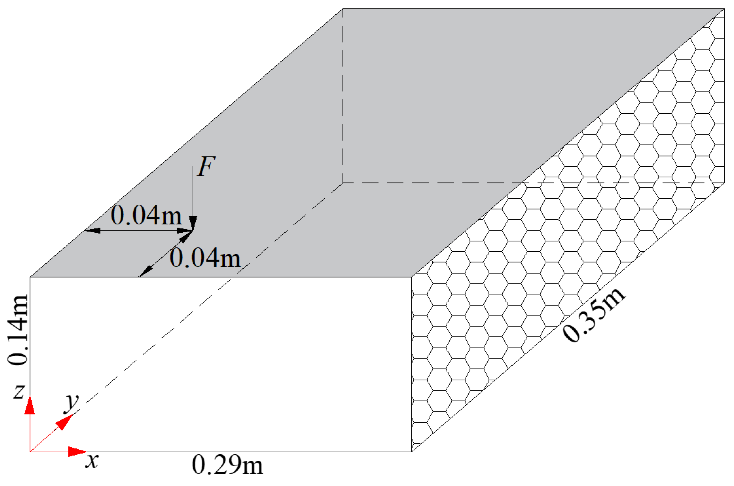
This section presents a numerical example to validate the accuracy and efficiency of the decoupled modal reduction method for vibro-acoustic analysis. As illustrated in Figure 2, a thin plate with dimensions of 0.29 × 0.35 m is positioned atop an acoustic cavity measuring 0.29 × 0.35 × 0.14 m. The right wall of the cavity is lined with sound-absorbing material, characterized by an impedance of Z = 416.5 kg / ( m 2 · s ) . The remaining surfaces of the cavity are assumed to be acoustically rigid. The thin plate is simply supported along all four edges and subjected to a vertical unit concentrated force, with the point of application located at coordinates (0.04, 0.04) m; the excitation frequency ranges from 1 Hz to 500 Hz. The material properties of the thin plate are as follows: Young’s modulus E = 210 GPa , Poisson’s ratio ν = 0.33 and mass density ρ s = 7850 kg / m 3 . The acoustic cavity is filled with air, where the speed of sound is c 0 = 340 m / s and mass density ρ a = 1.225 kg / m 3 .
The finite element model of the aforementioned vibro-acoustic system is established using linear elements. The thin plate is discretized with 4-node quadrilateral elements, while the sound field is represented by 8-node hexahedral elements. An element size of 9 mm is employed for both the cavity and the plate. In total, the finite element model of the cavity comprises 19,968 elements and 22,440 nodes; conversely, the finite element model of the thin plate consists of 1248 elements and 1320 nodes.The response of the vibro-acoustic system is computed utilizing three methods: the direct method, the coupled modal method and a novel approach presented in this paper. A frequency step of 1 Hz is adopted for these calculations. It should be noted that in the coupled modal method, coupled modes are not derived by directly solving for generalized eigenvalues from coupled stiffness and mass matrices. Instead, they are obtained through a technique outlined in Ref. [18], which employs superposition of decoupled modes to enhance solution efficiency within this framework.
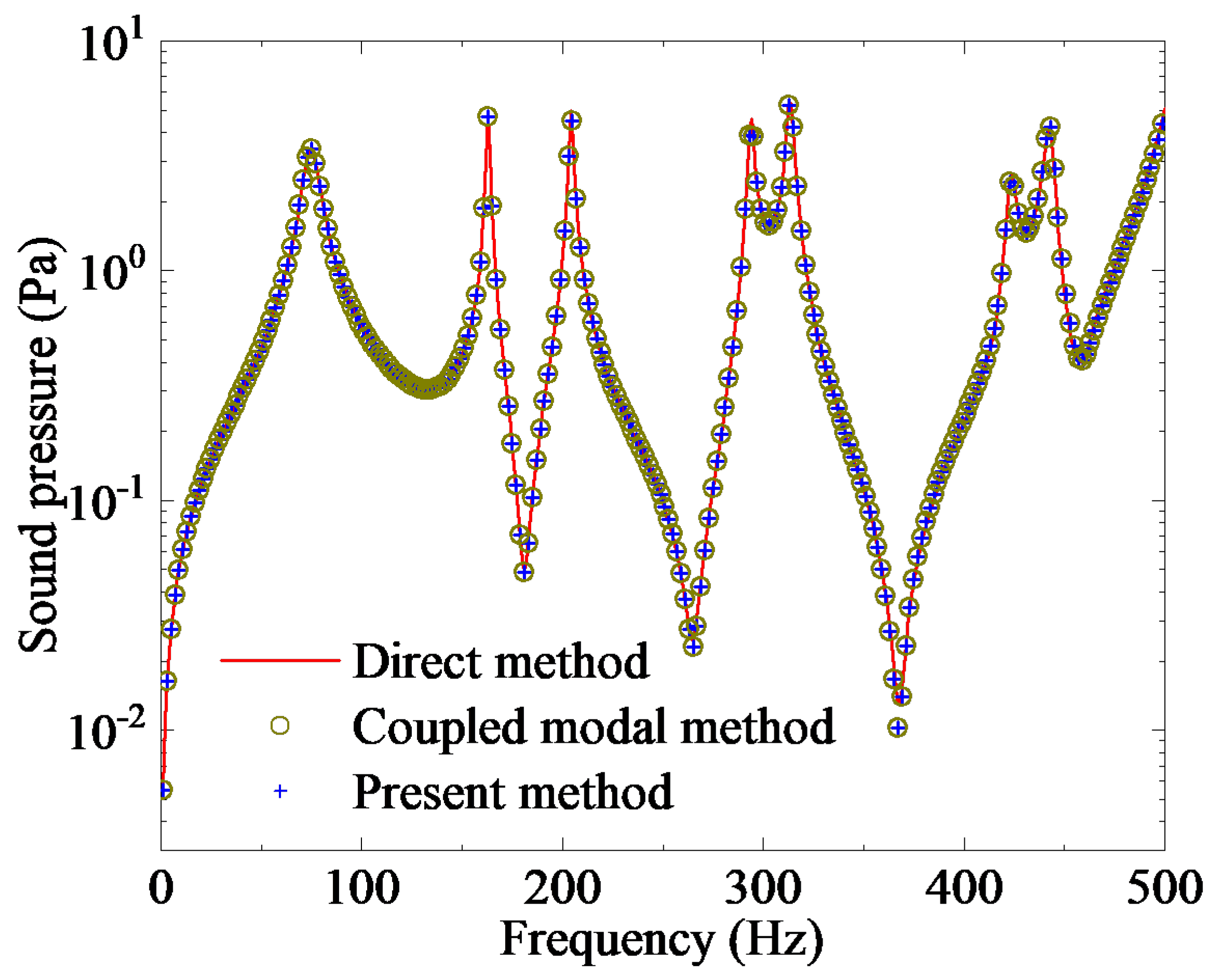
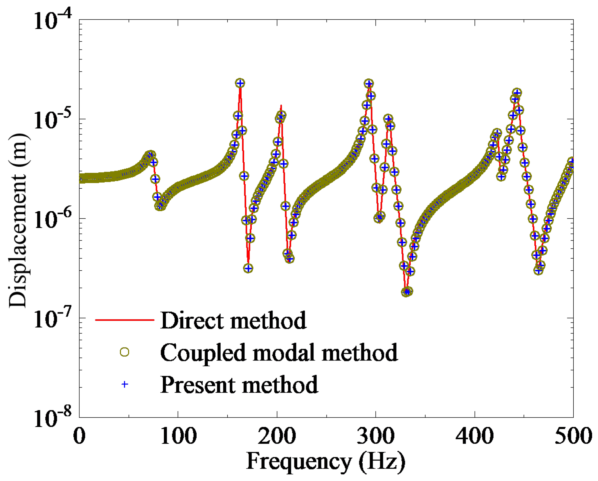
To validate the accuracy of the method proposed in this paper, results obtained from the direct method are utilized as a reliable reference solution. For both the coupled modal method and the approach presented herein, the modal truncation frequency for both the cavity and plate is established at 5000 Hz. Figure 3 illustrates a comparison of sound pressure amplitude at a point with coordinates (55.90 mm, 0.00 mm, 61.25 mm) calculated using the direct method, coupled modal method and our proposed method. Figure 4 provides a comparison of transverse displacement amplitude at the excitation point of the plate as determined by all three methods. It can be observed from Figure 3 and Figure 4 that results derived from our proposed method exhibit excellent agreement with those obtained through both the direct and coupled modal methods.
To further validate the accuracy of the method proposed in this paper, Figure 5 illustrates the spatial distribution of sound pressure amplitude and structural displacement calculated at a frequency of 400 Hz using three approaches: the direct method, the coupled modal method and the method introduced in this study. As shown in Figure 5, there is a strong agreement among all three methods regarding both the sound pressure distribution within the cavity and the plate displacement. However, it is important to note that due to modal truncation inherent in modal-based reduction techniques, slight local discrepancies exist between the cavity sound pressure results obtained from the coupled modal method and those derived from this paper’s approach when compared to those produced by the direct method.
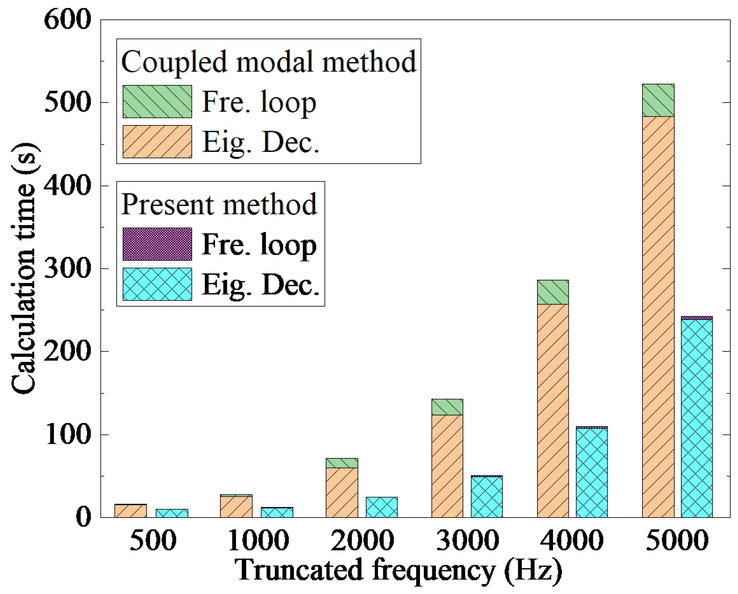
To validate the high solution efficiency of the method proposed in this paper, multiple calculations were conducted using various truncation frequencies. Table 1 presents the number of truncated modes for both the cavity and the plate corresponding to different truncation frequencies, along with the computation times required by the direct method, the coupled modal method and the approach introduced in this study. It is evident that, when compared to both the direct method and the coupled modal method, our proposed method demonstrates a significant advantage in terms of efficiency.
It is important to note that both the coupled modal method and the approach presented in this paper necessitate the resolution of two eigenvalue problems prior to initiating the frequency sweep. To provide a more detailed illustration of the time expenditure across various calculation stages, Figure 6 compares the duration spent on each stage of computation. It is evident that the method proposed in this paper requires approximately twice as much time as the coupled modal method during the eigenvalue calculation phase; however, it demonstrates significantly reduced time consumption during the frequency sweep stage, achieving computational efficiency exceeding ten times that of the coupled modal method. Furthermore, as truncation frequency increases, the rate at which time expenditure rises for the coupled modal method surpasses that of our proposed approach. All computations conducted in this study were implemented using Julia (1.0.2) and executed on a personal computer equipped with a 4-core, 3.3 GHz Intel Xeon processor and 32 GB of RAM while operating under Windows 11 OS.
It is important to note that eigenvalue decomposition is independent of frequency. Consequently, for a specific working condition, this calculation stage need only be performed once throughout the entire computational process. In contrast, the computational cost associated with the frequency sweep stage is contingent upon the number of calculation frequency points. Therefore, the method presented in this paper demonstrates a significant efficiency advantage for problems that necessitate response calculations across a large number of frequencies.

4. Conclusions

This paper presents a decoupled modal reduction method for addressing the steady-state vibration problem in vibro-acoustic systems characterized by non-classical damping. The proposed approach initially employs decoupled modes to reduce the order of the coupled governing equations associated with the vibro-acoustic system. Subsequently, it incorporates the complex modal superposition method to effectively manage non-classical damping. By utilizing decoupled modes, this method eliminates the necessity of solving for coupled modes as required in traditional modal reduction techniques, while the application of complex modal superposition facilitates the decoupling of governing equations that involve non-classical damping, thereby enhancing computational efficiency. Numerical examples demonstrate that both sound pressure and displacement responses obtained through this methodology align closely with those derived from direct methods and coupled modal approaches, thereby validating its accuracy. A comparative analysis of computation times among these three methodologies indicates that our proposed method exhibits superior computational efficiency, underscoring its effectiveness. Furthermore, given that modal decomposition is independent of frequency, an examination of computational efficiency across various stages further substantiates that our approach offers a pronounced advantage in terms of efficiency for problems spanning a broad frequency range.

Author Contributions

Conceptualization, R.G. and S.F.; methodology, R.G. and S.F.; software, R.G. and S.F.; validation, R.G. and S.F.; formal analysis, R.G. and S.F.; investigation, R.G. and S.F.; resources, R.G. and S.F.; data curation, R.G. and S.F.; writing—original draft preparation, R.G. and S.F.; writing—review and editing, R.G. and S.F.; visualization, R.G. and S.F.; supervision, R.G. and S.F.; project administration, R.G.; funding acquisition, R.G. All authors have read and agreed to the published version of the manuscript.

Funding

The authors acknowledge financial support from the Beijing Institute of Technology Research Fund Program for Young Scholars and the National Natural Science Foundation of China (12102045).

Data Availability Statement

The data presented in this study are available on request from the corresponding author.

Acknowledgments

Thanks to the magazine editors for their careful work and to the reviewers for their valuable comments.

Conflicts of Interest

The authors declare no conflicts of interest.

References

  1. Harari, I. A survey of finite element methods for time-harmonic acoustic. Comput. Methods Appl. Mech. Eng. 2006, 195, 1594–1607. [Google Scholar] [CrossRef]
  2. Legay, A. An extended finite element method approach for structural-acoustic problems involving immersed structures at arbitrary positions. Int. J. Numer. Methods Eng. 2013, 93, 376–399. [Google Scholar] [CrossRef]
  3. Junger, M.C.; Feit, D. Sound, Structures, and Their Interaction; MIT Press: Cambridge, MA, USA, 1972. [Google Scholar]
  4. Cremer, L.; Heckl, M.; Petersson, B.A.T. Structure-Borne Sound, 3rd ed.; Springer: Berlin, Germany, 2005. [Google Scholar]
  5. Zienkiewicz, O.C.; Taylor, R.L. The Finite Element Method, 5th ed.; Butterworth-Heinemann: Boston, MA, USA, 2000. [Google Scholar]
  6. Bathe, K.J. Finite Element Procedures; Prentice Hall: Upper Saddle River, NJ, USA, 1996. [Google Scholar]
  7. Atalla, N.; Sgard, F. Finite Element and Boundary Methods in Structural Acoustics and Vibration; CRC Press: Boca Raton, FL, USA, 2015. [Google Scholar]
  8. Wu, T.W. Boundary Element Acoustics: Fundamentals and Computer Codes; WIT: Southampton, UK, 2000. [Google Scholar]
  9. Golberg, M.A.; Chen, C.S. Discrete Projection Methods for Integral Equations; Computational Mechanics Publication: Southampton, UK, 1996. [Google Scholar]
  10. Koopmann, G.H.; Song, L.; Fahnline, J.B. A method for computing acoustic fields based on the principle of wave superposition. J. Acoust. Soc. Am. 1989, 86, 2433–2438. [Google Scholar] [CrossRef]
  11. Chen, W.; Gu, Y. Recent advances on singular boundary method. Joint Int. Workshop Trefftz Method 2011, 4, 543–558. [Google Scholar]
  12. Desmet, W. A Wave Based Prediction Technique for Coupled Vibro-Acoustic Analysis. Ph.D. Thesis, K.U. Leuven, Leuven, Belgium, 1998. [Google Scholar]
  13. Van Genechten, B.; Vandepitte, D.; Desmet, W. A direct hybrid finite element-wave based modelling technique for efficient coupled vibro-acoustic analysis. Comput. Methods Appl. Mech. Eng. 2011, 200, 742–764. [Google Scholar] [CrossRef]
  14. Everstine, G.C.; Henderson, F.M. Coupled finite element/boundary element approach for fluid-structure interaction. J. Acoust. Soc. Am. 1990, 87, 1938–1947. [Google Scholar] [CrossRef]
  15. Amini, S.; Harris, P.J.; Wilton, D.T. Coupled Boundary and Finite Element Methods for the Solution of the Dynamic Fluid-Structure Interaction Problem; Springer: Berlin, Germany, 1992. [Google Scholar]
  16. Atak, O.; Bergen, B.; Huybrechs, D.; Pluymers, B.; Desmet, W. Coupling of boundary element and wave based methods for the efficient solution of complex multiple scattering problems. J. Comput. Phys. 2014, 258, 165–184. [Google Scholar] [CrossRef]
  17. Ma, Z.D.; Hagiwara, I. Sensitivity analysis methods for coupled acoustic-structural systems part II: Direct frequency response and its sensitivities. AIAA J. 1991, 29, 1796–1801. [Google Scholar] [CrossRef]
  18. Luo, J.; Gea, H.C. Modal sensitivity analysis of coupled acoustic-structural systems. J. Vib. Acoust. 1997, 119, 545–550. [Google Scholar] [CrossRef]
  19. Bathe, K.J.; Nitikitpaiboon, C.; Wang, X. A mixed displacement-based finite element formulation for acoustic fluid-structure interaction. Comput. Struct. 1995, 56, 225–237. [Google Scholar] [CrossRef]
  20. Everstine, G.C. Finite element formulations of structural acoustics problems. Comput. Struct. 1997, 65, 307–321. [Google Scholar] [CrossRef]
  21. Sandberg, G.; Goransson, P. A symmetric finite element formulation for acoustic fluid-structure interaction analysis. J. Sound Vib. 1988, 123, 507–515. [Google Scholar] [CrossRef]
  22. Wolf, J.A. Modal synthesis for combined structural-acoustic systems. AIAA J. 1976, 14, 33–38. [Google Scholar] [CrossRef]
  23. Géradin, M.; Rixen, D. Mechanical Vibrations: Theory and Applications to Structural Dynamics, 2nd ed.; John Wiley & Sons Inc.: Hoboken, NJ, USA, 2015. [Google Scholar]
Figure 1. Schematic diagram of the coupled vibro-acoustic system.
Acoustics 06 00044 g001
Figure 2. The vibro-acoustic system consisting of a rectangular thin plate and a cuboidal acoustic cavity. The grey area represents the elastic thin plate, while the hexagonally patterned area indicates the sound-absorbing material.
Acoustics 06 00044 g002
Figure 3. Comparison of the sound pressure amplitude at a point inside the cavity calculated by the three methods.
Acoustics 06 00044 g003
Figure 4. Comparison of the displacement amplitude at a point on the thin plate calculated by the three methods.
Acoustics 06 00044 g004
Figure 5. The spatial distribution of sound pressure amplitude and structural displacement calculated by the three methods. (a,c,e) represent the sound pressure distribution in the cavity calculated by the direct method, the coupled modal method and the proposed method, respectively; (b,d,f) represent the displacement distribution of the thin plate calculated by the direct method, the coupled modal method and the proposed method, respectively.
Acoustics 06 00044 g005
Figure 6. Comparison of time costs at different calculation stages between the method of this paper and the coupled modal method.
Acoustics 06 00044 g006
Table 1. The number of modes for the cavity and the plate at different truncation frequencies and the computation time of the three methods.
Truncation
Frequency (Hz)
Number of
Truncated Modes
Time Cost (s)
Cavity Plate Traditional
Reduction Method
Decoupled Modal
Reduction Method
Direct
Method
5002716.29.9911,037
100051727.911.97
2000263671.724.6
30006657142.950.3
400014180286.3109.8
500024599522.4242.3
Disclaimer/Publisher’s Note: The statements, opinions and data contained in all publications are solely those of the individual author(s) and contributor(s) and not of MDPI and/or the editor(s). MDPI and/or the editor(s) disclaim responsibility for any injury to people or property resulting from any ideas, methods, instructions or products referred to in the content.