Abstract
We are examining the behavior of resonance frequencies and their response to variations of material parameters such as thicknesses, masses, and bulk velocities for certain Rayleigh–Lamb acoustic modes in a multilayered structure. The treatment is based on recent explicit analytic solutions that have allowed us to explore the entire parametric space using dimensionless ratios. This exploration has revealed a complex parametric dependence of the phase velocities and their mass loading response. Specifically, for the fundamental flexural modes in a bilayer, we have shown that both quantities change in a strongly non-monotonic way with thickness, density, or bulk velocity ratios. Even in the regime of thin coating, commonly encountered in acoustic sensing applications, we have found important differences from previously known results, e.g., that response to loading may switch its sign multiple times when the velocity of the deposited material is increased. We have also discovered that the fundamental dilatational modes can be highly effective in stabilizing resonant frequencies against even large variations of the thickness or mass of the exposed layer. This property is demonstrated in an explicit form by the derived expression for the mass coefficient of frequency for an arbitrary number of layers.
1. Introduction
Due to the ubiquitous nature of acoustic vibrations and a direct dependence on the properties of the propagation medium, ability to interact with other excitations and need to keep a low attenuation rate, they demonstrate a broad diversity of applications ranging from the macro- to nanoscale, showing classical or quantum behavior In the commonly encountered bounded layered structures like thin films, membranes, plates, etc., acoustic spectra are described by the waves of the Rayleigh–Lamb (RL) type [1,2,3,4,5] and consist of an involved arrangement of frequency–wavenumber dispersion curves , where q is the in-plane wavenumber, is the band index and p is the polarization. At long wavelengths, the curves terminate at finite cutoff values except for a few fundamental branches, such as and the gapless shear horizontal, flexural (F) and dilatational (D) modes (we have dropped the p subscript). At shorter wavelengths, most of the curves converge towards bulk shear and longitudinal velocities and some evolve into evanescent surface or interface-guided modes, including the famous Rayleigh surface acoustic waves. However, knowledge of the band structure is insufficient for applications where one also needs to know the way it changes with various parameters. For example, consider semiconductor or metal-insulator wafers with a thickness of a few dozen nanometers that are the main components of electronic ultra-low power detectors or on-chip microcoolers [6,7]. One of the key processes is the transfer of heat carried by electrons and its dissipation by the RL phonon modes of the numerous dispersion branches, which in turn depend on a set of material and structural parameters, consisting of thicknesses of the layers , bulk shear and longitudinal velocities, elastic constants, mass densities , etc. [8,9]. The intensity of the electron–phonon heat transfer can be increased by an order of magnitude by reducing layer thicknesses; however, there exists a large variation between specimens of different materials [10]. Because any particular set of parametric values corresponds to just a single point in a multidimensional space, there exists a fundamental and practical interest in finding more explicit dependence of the band structure on parametric coordinates using analytic or semi-analytic results. For instance, in [11], it has been shown that by increasing the number of layers with an alternating ratio of elastic constants, the rearrangement of the band structure can result in the accumulation or depletion of the density of states in a specified spectral region. This property is relevant for, e.g., thermal transport and for tuning of electron–phonon and magneto-acoustic coupling in microelectronics and spintronics [12,13]. On the other hand, many applications (e.g., in acoustic sensing) spotlight the dependence of separate RL modes on external factors due to their effect on [4,14]. This principle is implemented in many types of modern microsensors on the basis of thin layer technologies measuring mass, temperature, pressure, humidity, gas concentration, etc. [15,16,17,18,19,20]. The relative simplicity of the layered structure gives advantages in fabrication and ensures low power consumption, excellent interfacing with electronics, compatibility with wireless data transmission and the ability of passive (battery-less) operation in both harsh and biological environments. Thus, such sensors using Rayleigh or Sezawa modes are successfully used in industry, biology, chemistry and medicine [21,22,23]. Analyzing the frequency response of RL cutoff modes are instrumental in the detection of defects or determination of the degree of corrosion in nondestructive testing [24]. The effect of mass loading on the frequency shift generated by metallic electrodes in film bulk acoustic resonators are used in the operation of modern 5G technology pass band filters [25]; the high-sensitivity resonators of this kind can detect masses down to femtograms [26].
Sensitivity, the key characteristic of such devices, is quantified by the shift of resonance frequency in response to an external factor (e.g., temperature, T) and can be defined in the form of the temperature coefficient of frequency (TCF):
Then, the relative variation of or of the phase velocity is driven by the temperature dependence of :
Here, is the linear thermal expansion coefficient due to the elongation of the device in the direction of wave propagation, i.e., it accounts for the change in the excited wavelength. The derivatives of are related to bulk thermal coefficients of, e.g., thickness, elastic constants, sound velocities, etc. [27,28], and similar considerations apply to pressure, humidity or other types of sensors. Therefore, to maximize the sensitivity, one needs to know the rate at which the acoustic band structure changes with parameters. For some applications, on the contrary, a reduced sensitivity is required to ensure the frequency stability of the resonance mode against a change in, e.g., temperature, pressure or mass [29]. Respectively, the condition identifies surfaces of relative stability towards variations in parameters. On the other hand, these surfaces are closely related to the monotonicity property of the dependence, i.e., the existence of a one-to-one correspondence between parameters and resonance frequencies, a basic characteristic of measurement and sensing devices. The non-monotonic behavior is signaled by the presence of maxima or minima of the with the condition that the second derivative does not switch its sign on the critical surface. These critical surfaces are therefore of significant interest both for applications exploiting the stability of the resonance frequencies and acoustic sensing, as higher values of and higher sensitivities are achieved in the regions further away from the surfaces. For instance, a nearly linear behavior of resonance frequencies with temperature, pressure or gas concentration is reported for sufficiently large working intervals in high-performance acoustic sensors based on Rayleigh, Sezawa and some Lamb waves [16,30,31,32]. The monotonic dependence on parameters has also been found in an analytical form by the perturbative calculation of the mass loading sensitivity in a two- and three-layer isotropic composite plate [15,33,34]. In particular, for sensors based on , fundamental dilatational and flexural waves, the sensitivity increases for thinner and lighter structures or with a higher contrast between the velocities of the layers.For a single layer, monotonic thickness dependence of the whole spectrum is well established, e.g., the phase velocities of the symmetric modes are decreasing functions of H, as illustrated in the Figure 1 for an iron plate.
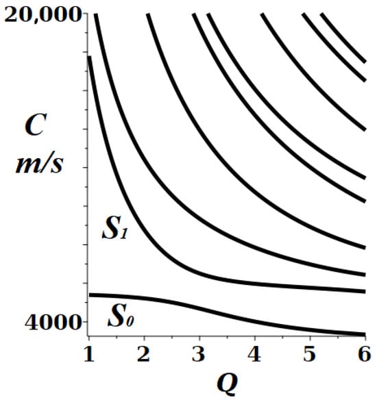
Figure 1.
Phase velocities C of the symmetric Rayleigh–Lamb modes in an plate ( m/s, m/s) decrease with thickness H for a fixed wavenumber q. Here, and with etc., are the corresponding branches of the spectrum.
For a bulk medium, parametric monotonicity can be understood by considering a transverse (or longitudinal) wave traversing a sequence of layers with respective velocities (or ). For the normal incidence, the effective velocity is determined by considering the total propagation time [35]:
where is the total thickness. Such elementary consideration turns out to be sufficiently reliable for estimating the crossover temperature of a thermal phonon gas from bulk to the confined (or quasi-2D) regime, even for nanometrically thin multilayers [6]. Note that the number of relevant independent parameters can be reduced by switching to scaled quantities, e.g., taking in Equation (3) gives , with just two independent parameters, and . This illustrates the physically transparent relation: unconditionally increases with as a faster material of any layer means a faster overall propagation. Also, either increases or decreases with a layer thickness depending on the given set of values for the other parameters (see below).
Nevertheless, the above monotonicity property can not be generally true, even for the spectrum of an isotropic traction-free plate, as recently demonstrated in [36]. One notable implication of the aforementioned exceptions is that acoustic plate waves can propagate with a higher speed in a slower medium (i.e., with a lower bulk velocity). The modes of the calculated band structure in the Figure 2 are an example of such an unconventional parametric dependence that can be compared with the totally regular one in Figure 1. It should also be mentioned that due to the large dimensionality of the parametric space, the frequency–wavenumber spectrum is known to have a number of different anomalies in this extended space, e.g., “diabolic” and exceptional crossing points, avoided crossing (osculation or veering) points related to degeneracy of quasi-degeneracy of the spectral surfaces [37,38,39,40]. The latter crossings have a conical character in the vicinity of such special points that may well involve a non-monotonic variation of frequency with [36,37]. The non-monotonicity of versus q dependence is also associated with anomalous zero and negative group velocity (ZNGV) modes [41,42,43,44], which have recently attracted special interest due to negative refraction and its application in the design of metamaterials or ultra-resolution acoustic lenses [45,46].
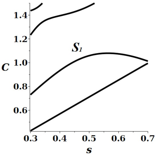
Figure 2.
Phase velocities C of the lowest symmetric RL spectral branches in a traction-free plate versus bulk shear velocity s (in units of longitudinal velocity ℓ) at a fixed dimensionless wavenumber, . The branch demonstrates a non-monotonic behavior.
However, non-monotonicity is not necessarily related to singularities or degeneracy of spectral lines and may take place in a large area of the parametric space, as has been known from calculations and experimental studies for particular materials and parameters of multilayer structures [41,47]. The analytical solutions considered below allow us to obtain and analyze explicit expressions for the response functions in the multidimensional parametric space and reveal some general properties of the RL modes relevant to sensing applications.
2. Parametric Non-Monotonicity of the RL Spectrum
In the short wavelength limit, , the spectrum becomes non-dispersive, group and phase velocities coincide, dependence on total thickness H disappears and, by analogy with bulk media, the monotonic parametric behavior can be expected. Indeed, this is easily verified by the asymptotic approximation in [48,49] for the velocity of the Rayleigh SAW in a single-layer plate. Its parametric derivatives are all strictly positive and only vanish at or outside the physical domain (where is Poisson’s ratio). The sensitivity (1) is then found as:
with (the lengthy explicit expression is not shown for brevity). Theoretical arguments show that the temperature dependence of bulk parameters in many solids is dominantly linear in sufficiently large temperature or pressure intervals [27,28] so that, according to (4), one can expect that values of the or (pressure coefficient of frequency defined by analogy with (1)) for the Rayleigh mode remain nearly constant at sufficiently short wavelengths. However, there are limited data on the measured temperature or pressure dependence of parameters such as s and in the literature, and it therefore could be possible to use similar explicit expressions for different modes in obtaining such complementary information.
In the opposite, long wavelength, limiting the fundamental dilatational mode appears to be the physically closest generalization of the bulk waves in multilayers (3) to finite H because of its linear frequency–wavenumber dispersion. Then, the general expression for the velocity of the mode in a traction-free multilayer [11] can be expressed in a form reduced to dimensionless scaled quantities:
where
N is the total number of layers, is the velocity of the fundamental symmetric Lamb mode in a single free plate and . Alternatively, related parameters can be used, , where and are the Lamé elastic constants (the index is omitted for brevity wherever confusion can be avoided). By following the arguments in the above discussion of bulk waves, we represent (5) in a suggestive form, revealing its similarity to the parametric dependence in (3).
where is the total mass per unit area ( exposed as top layer). Indeed, here we have an additive or linear superposition of mass and “kinetic energy” contributions that demonstrates a completely monotonic behavior of the mode in the multidimensional parametric space. This form is convenient for the analysis of mass loading response, and we readily obtain a generalization of the earlier result [15] to the sensitivity function of a structure with an arbitrary number of layers:
Importantly, the condition does not involve the mass of the exposed layer, and the equation explicitly demonstrates how one can achieve a perfect mass loading stabilization effect for the dilatational wave in a multilayer. For a bilayer, this possibility is irrelevant because it imposes an unrealistic condition that the two materials are of the same velocity . However, for a larger number of layers, this restriction is not necessary, and mass stabilization of the resonance frequency can be achieved by an appropriate adjustment of the thickness or mass ratios for the layers other than . Similar to bulk waves, the physical cause of such a cancellation is that in this way, effective velocities of the sub-sets of N layers can become equal to each other, as follows from (7) and (8). For example, when , the condition can be satisfied by choosing the masses or thicknesses of the layers 1 and 2 in such a way that:
Note that when such a condition is fulfilled, , all of the higher order derivatives in vanish as well. The above similarity with the bulk waves can be proven further: if the effective velocity of a double layer is the same as , then it also equals the velocity of the composite structure .
Similarly, and other coefficients can be easily obtained from (7):
In particular, the for a single layer (when , the symmetric Lamb mode) may provide information complementary to (4) in finding the temperature coefficients of bulk materials:
as all the derivatives remain finite. It can be shown that the rest of the long wavelength modes follow a qualitatively different, non-monotonic behavior in the parametric space. Here, we focus on the example where the explicit solution has been found recently.
Let us consider the fundamental flexural wave (F), the lowest velocity branch of the RL spectrum in a bilayered traction-free plate, , of total thickness H. The analytical expression obtained in [50] allows us to consider this issue in the full parametric range and extend the earlier perturbative results for the response functions to, e.g., finite masses and thicknesses:
Here, is the reference velocity of the fundamental antisymmetric mode corresponding to a single free plate, of thickness , so that (the layer index at has been dropped; henceforth, ). In Equation (11), the dimensionality of the whole set of parameters has been reduced to only three independent variables, and the parametric response functions can be calculated in an explicit form. The result for the mass loading sensitivity is given in Appendix A. We also note that due to the known restriction on Poisson’s ratio, , one of the contributing quantities has a limited variation interval, . Moreover, for most of commonly used solids, their values are close to unity, , and we therefore assume . Then, examination of the expression in Appendix A of the first derivative with respect to the ratio (or, essentially, with respect to shear velocity if is fixed as a reference layer) shows that it never crosses zero and proves that is strictly monotonic in this parameter. However, dependence of the flexural mode on the thickness or mass ratios shows a rather different behavior. Note that if the mass densities remain constant, then mass and thickness variations are equivalent . As discussed above, the essential properties of response functions can then be understood by considering the surfaces of the vanishing parametric derivative , shown in Figure 3. To represent the full interval of thickness ratios , it is convenient to switch to the scaled variable, .
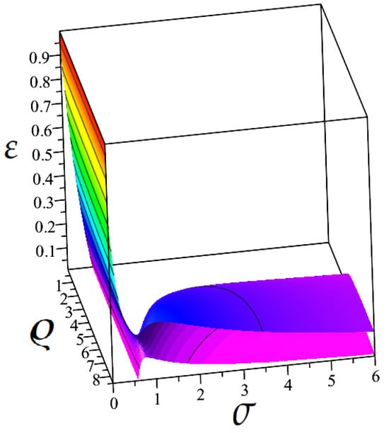
Figure 3.
Solution of the , vanishing sensitivity to mass loading of the flexural mode in a bilayer, Equation (11). The surfaces separate parametric regions with different signs of the response function . Here, the complete set of parameters is represented by the density, bulk velocity and thickness ratios, . Color shades correspond to the values of .
First, it can be easily shown that expression (11) confirms the known result for the thin coating limit ( in Reference [15]):
In Figure 3, the term in parentheses corresponds to the straight line in the base plane . The regions separated by the colored surface in this three-dimensional graph correspond to a monotonic behavior (constant sign of the derivative ). If velocity of the F-mode would change monotonically with the thickness of the added layer [33], then the critical surface in the figure should be strictly vertical, because the solution of this equation would not depend on or (Table 1 in [15]), similar to the dilatational mode discussed earlier. However, our expression leads to a different behavior and, instead, we obtain a strongly curved and folded surface when . In Figure 4 and Figure 5, a few cross-sections of this surface are shown. These results demonstrate that the response function can also have multiple extrema and change its sign several times as a function of thickness, density and bulk velocity ratios. Surprisingly, these new extrema are found even for the thin coating regime () in a large area of values, and they are found away from those described by the slanted surface that crosses the plane in Figure 3 (also seen as the lowest curve in the Figure 5). This crossing corresponds to the known result in (12), . Note that the obtained non-trivial behavior of the critical surface does not reveal itself in a perturbative treatment. The slanted part of the surface can be approximated by for and (as shown in Appendix A). Moreover, to clarify whether these extrema correspond to maxima (minima) or to the inflection points of the , we also show in Figure 6 the critical surface of the second derivatives . From these figures, it can be concluded that the mass and thickness response of the F-mode shows a strongly non-monotonic behavior for a broad range of material parameters at small values of , while at some larger values, there exists an area of enhanced stability of the resonance frequencies (Figure 7). The reason becomes clear if one notices that when both first and second parametric derivatives vanish at the intersection of gray and colored surfaces, Figure 6, the frequency of the F-wave shows the weakest sensitivity to mass or thickness variation. As soon as the thickness of the second layer becomes sufficiently large, , the frequency varies monotonically with , and crossing the gray surface only signals a change in curvature in the parametric dependence. The exception belongs to the case when the material of the second layer has a smaller bulk velocity, Then, the vanishing of the mass or thickness response can take place at any ratio . However, as the second derivative in does not cross zero in this area (see Figure 6), the phase velocity behaves in a strictly non-monotonic way, i.e., it has parametric maxima and minima, Figure 8. For the domain limited by the conditions and , the resonance frequency of the F-wave varies in a monotonic way in the full range of all of its parameters and, respectively, shows a non-vanishing response to their variation.
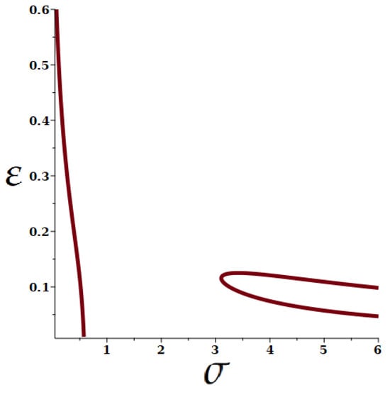
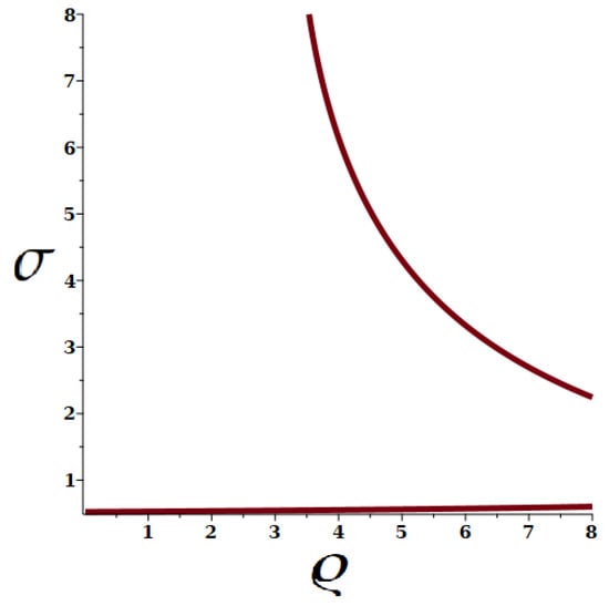
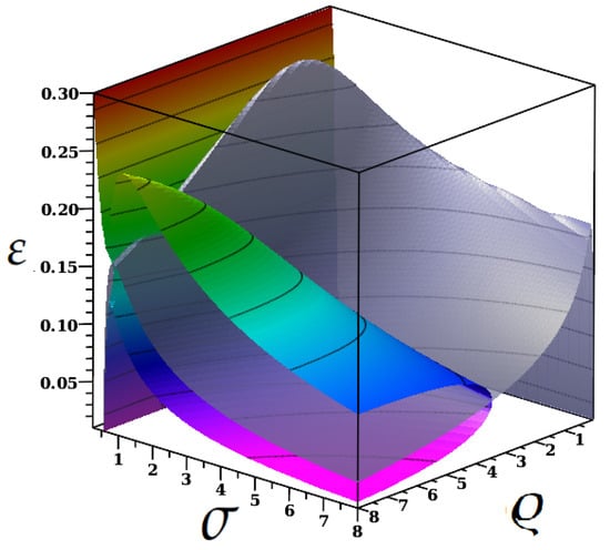
Figure 6.
The critical surface of Figure 3 (colored) as compared with the surface (gray, half-transparent). Color shades correspond to the values of . Their crossing takes place at intermediate values of the thickness ratio () and corresponds to materials with an enhanced stability of the resonance frequencies towards mass loading. The rest of the critical surface corresponds to maxima or minima in the thickness dependence of the resonance frequencies. The associated behavior of the phase velocities is illustrated in the figures below.
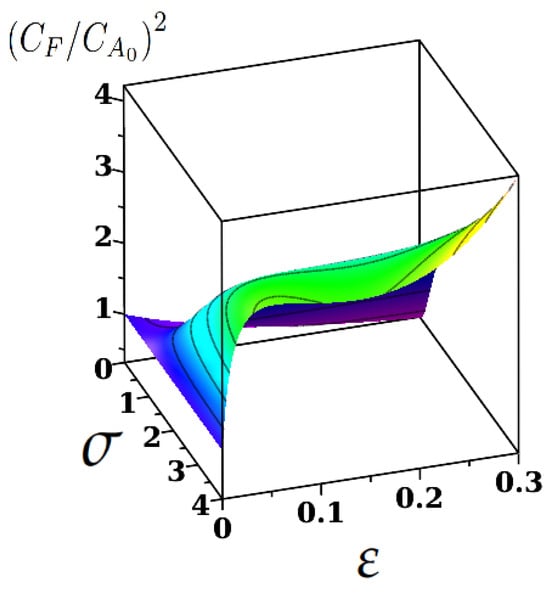
Figure 7.
Illustration of the enhanced stability of the resonance frequency region variation of the phase velocity at a fixed value of mass density ratio, . Color shades correspond to the values of . To be compared with the cross-section of Figure 6, explaining the stabilization criteria for the resonance frequency of the flexural mode.
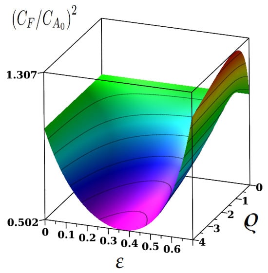
Figure 8.
Variation of the phase velocity at a fixed value of the bulk ratio, . Color shades correspond to the values of . To be compared with the corresponding cross-section of Figure 6, where corresponds to extrema of the .
3. Discussion and Conclusions
We have analyzed the behavior of acoustic resonance frequencies and their response to the variation of material parameters for certain Rayleigh–Lamb modes of multilayered structures. Based on explicit analytic expressions, we have considered the entire parametric space in terms of dimensionless ratios, allowing us to reveal some qualitatively new features relevant to thin-membrane acoustic sensing applications. Thus, we have found that the flexural wave’s mass loading sensitivity depends non-monotonically on thickness, density, or bulk velocity ratios, even in the thin coating regime. We have identified the regions of parametric space where one can expect enhanced or reduced sensitivity to mass loading, with purely monotonic and predictable dependence on material parameters. We have demonstrated that the dilatational mode in multilayers offers unique possibilities in applications that require the stabilization of acoustic resonance frequencies with respect to thickness or mass variation and have explained the physical nature of this property. We have also discussed the possibility of using the analytic form of the obtained expressions in exploring the dependence of material parameters on external factors (temperature, pressure, humidity, etc.), which can stimulate further research.
Funding
This work was financially supported by MCID Romania (project no. PN 23 21 01 01/2023).
Data Availability Statement
The original contributions presented in the study are included in the article, further inquiries can be directed to the corresponding author.
Conflicts of Interest
The author declares no conflict of interest.
Abbreviations
The following abbreviations are used in this manuscript:
| RL | Rayleigh–Lamb |
| MCF | Mass coefficient of frequency |
| TCF | Temperature coefficient of frequency |
| D, F | Subscripts for dilatational and flexural |
Appendix A
The response function of the flexural mode, Equation (11), describes its velocity variation in response to a small change of mass for the layer, , assuming that only its thickness changes, e.g., at constant temperature. Then, in terms of the ratios defined in the text, we have
resulting in a rather complex behavior described by the explicit form below
The vanishing of this coefficient defines the critical surface in the multiparametric space discussed in the paper. The linear approximation at small (the last two terms in the numerator) following from the above expression corresponds to the slanted quasi-flat surface in Figure 3 and Figure 6. However, as discussed in the text, this approximation quickly deteriorates already at (e.g., Figure 4 and Figure 5) as the surface becomes strongly curved, resulting in a non-monotonous behavior of the response function in the parametric space .
By contrast, velocity of the flexural mode is completely monotonic in the ratio because its derivative is finite for any choice of parameters:
References
- Malischewsky, P.G. Surface Waves and Discontinuities; Akademie Verlag: Berlin, Germany, 1987. [Google Scholar]
- Auld, B.A. Acoustic Fields and Waves in Solids; Krieger: Malabar, FL, USA, 1990. [Google Scholar]
- Graff, K.F. Wave Motion in Elastic Solids; Dover Publications: New York, NY, USA, 1991. [Google Scholar]
- Cheeke, J.D.N. Fundamentals and Applications of Ultrasonic Waves, 2nd ed.; CRC Press: Boca Raton, FL, USA, 2012. [Google Scholar]
- Rose, J.L. Ultrasonic Guided Waves in Solid Media; Cambridge University Press: Cambridge, UK, 2014. [Google Scholar]
- Saira, O.-P.; Matheny, M.H.; Wang, L.; Pekola, J.; Roukes, M. Modification of electron-phonon coupling by micromachining and suspension. J. Appl. Phys. 2020, 127, 024307. [Google Scholar] [CrossRef]
- Tarasov, M.; Gunbina, A.; Chekushkin, A.; Yusupov, R.; Edelman, V.; Koshelets, V. Microwave SINIS Detectors. Appl. Sci. 2022, 12, 10525. [Google Scholar] [CrossRef]
- Stroscio, M.A.; Dutta, M. Phonons in Nanostructures; Cambridge University Press: Cambridge, UK, 2001.
- Cojocaru, S.; Anghel, D.V. Low-temperature electron-phonon heat transfer in metal films. Phys. Rev. B 2016, 93, 115405. [Google Scholar] [CrossRef]
- Nguyen, H.Q.; Meschke, M.; Courtois, H.; Pekola, J.P. Sub-50-mK Electronic Cooling with Large-Area Superconducting Tunnel Junctions. Phys. Rev. Appl. 2014, 2, 054001. [Google Scholar] [CrossRef]
- Kuznetsov, S.V. Abnormal Dispersion of Lamb Waves in Stratified Media. Z. Angew. Math. Phys. 2019, 70, 175. [Google Scholar] [CrossRef]
- Sasaki, R.; Nii, Y.; Onose, Y. Magnetization Control by Angular Momentum Transfer from Surface Acoustic Wave to Ferromagnetic Spin Moments. Nat. Commun. 2021, 12, 2599. [Google Scholar] [CrossRef]
- Peria, W.K.; Zhang, D.-L.; Fan, Y.; Wang, J.-P.; Crowell, P.A. Anomalous Temperature Dependence of Phonon Pumping by Ferromagnetic Resonance in Co/Pd Multilayers with Perpendicular Anisotropy. Phys. Rev. B 2022, 106, L060405. [Google Scholar] [CrossRef]
- Ballantine, D.S.; White, R.M.; Martin, S.J.; Ricco, A.J.; Zellers, E.T.; Frye, G.C.; Wohltjen, H.; Levy, M.; Stern, R. Acoustic Wave Sensors: Theory, Design and Physico-Chemical Applications; Academic Press: Burlington, UK, 1997. [Google Scholar]
- Cheeke, J.D.N.; Wang, Z. Acoustic Wave Gas Sensors. Sens. Actuators Chem. 1999, 59, 146–153. [Google Scholar] [CrossRef]
- Müller, A.; Konstantinidis, G.; Giangu, I.; Adam, G.C.; Stefanescu, A.; Stavrinidis, A.; Stavrinidis, G.; Kostopoulos, A.; Boldeiu, G.; Dinescu, A. GaN Membrane Supported SAW Pressure Sensors With Embedded Temperature Sensing Capability. IEEE Sens. J. 2017, 17, 7383–7393. [Google Scholar] [CrossRef]
- Gholami, F.; Shih, A.; Robichaud, A.; Cicek, P.-V. A Study of Optimizing Lamb Wave Acoustic Mass Sensors Performance through Adjustment of the Transduction Electrode Metallization Ratio. Sensors 2022, 22, 6428. [Google Scholar] [CrossRef]
- Zhang, Y.; Tan, Q.; Zhang, L.; Zhang, W.; Xiong, J. A Novel SAW Temperature-Humidity-Pressure (THP) Sensor Based on LiNbO3 for Environment Monitoring. J. Phys. Appl. Phys. 2020, 53, 375401. [Google Scholar] [CrossRef]
- Boldeiu, G.; Ponchak, G.E.; Nicoloiu, A.; Nastase, C.; Zdru, I.; Dinescu, A.; Müller, A. Investigation of Temperature Sensing Capabilities of GaN/SiC and GaN/Sapphire Surface Acoustic Wave Devices. IEEE Access 2022, 10, 741–752. [Google Scholar] [CrossRef]
- Nicoloiu, A.; Boldeiu, G.; Nastase, C.; Nedelcu, M.; Ciornei, C.; Zdru, I.; Stavrinidis, G.; Vasilache, D.; Stavrinidis, A.; Dinescu, A.; et al. Experimental Analysis of Rayleigh and Sezawa Modes Resonance Frequencies in SAW Devices Manufactured on Sc0.3Al0.7N/Si. IEEJ Trans. Electr. Electron. 2024, 19, 900–907. [Google Scholar] [CrossRef]
- Zhou, J.; Guo, Y.; Wang, Y.; Ji, Z.; Zhang, Q.; Zhuo, F.; Luo, J.; Tao, R.; Xie, J.; Reboud, J.; et al. Flexible and Wearable Acoustic Wave Technologies. Appl. Phys. Rev. 2023, 10, 021311. [Google Scholar] [CrossRef]
- Xu, Z.; Yuan, Y.J. Implementation of Guiding Layers of Surface Acoustic Wave Devices: A Review. Biosens. Bioelectron. 2018, 99, 500–512. [Google Scholar] [CrossRef]
- Baumgartner, K.; Westerhausen, C. Recent Advances of Surface Acoustic Wave-Based Sensors for Noninvasive Cell Analysis. Curr. Opin. Biotechnol. 2023, 79, 102879. [Google Scholar] [CrossRef]
- Cao, X.; Zeng, L.; Lin, J.; Hua, J. A Correlation-Based Approach to Corrosion Detection with Lamb Wave Mode Cutoff. J. Nondestruct. Eval. 2019, 38, 87. [Google Scholar] [CrossRef]
- Liu, Y.; Cai, Y.; Zhang, Y.; Tovstopyat, A.; Liu, S.; Sun, C. Materials, Design, and Characteristics of Bulk Acoustic Wave Resonator: A Review. Micromachines 2020, 11, 630. [Google Scholar] [CrossRef]
- Ren, J.; Chu, H.; Bai, Y.; Wang, R.; Chen, P.; Chen, J. Research and Design of High Sensitivity FBAR Micro-Mass Sensors. In IOP Conference Series: Earth and Environmental Science, Volume 632, 2020 Asia Conference on Geological Research and Environmental Technology, Kamakura City, Japan, 10–11 October 2020; IOP Publishing: Bristol, UK, 2021; Volume 632, p. 042014. [Google Scholar]
- Ledbetter, H. Sound Velocities, Elastic Constants: Temperature Dependence. Mater. Sci. Eng. A 2006, 442, 31–34. [Google Scholar] [CrossRef]
- Zakarian, D.; Khachatrian, A.; Firstov, S. Universal Temperature Dependence of Young’s Modulus. Met. Powder Rep. 2019, 74, 204–206. [Google Scholar] [CrossRef]
- Liu, X.; Ren, X.; Tang, M.; Wang, Y.; Xu, Z.; Yan, Y. Superior Temperature Stability of Electromechanical Properties and Resonant Frequency in PYN-PZT Piezoelectric Ceramics. J. Eur. Ceram. Soc. 2024, 44, 873–881. [Google Scholar] [CrossRef]
- Aslam, M.Z.; Jeoti, V.; Karuppanan, S.; Malik, A.F.; Iqbal, A. FEM Analysis of Sezawa Mode SAW Sensor for VOC Based on CMOS Compatible AlN/SiO2/Si Multilayer Structure. Sensors 2018, 18, 1687. [Google Scholar] [CrossRef] [PubMed]
- Nicoloiu, A.; Stan, G.E.; Nastase, C.; Boldeiu, G.; Beşleagă, C.; Dinescu, A.; Müller, A. The Behavior of Gold Metallized AlN/Si- and AlN/Glass-Based SAW Structures as Temperature Sensors. IEEE Trans. Ultrason. Ferroelectr. Freq. Control 2021, 68, 1938–1948. [Google Scholar] [CrossRef]
- Vasilache, D.; Nicoloiu, A.; Boldeiu, G.; Zdru, I.; Kostopoulos, T.; Nedelcu, M.; Stavrinidis, A.; Nastase, C.; Stavrinidis, G.; Konstantinidis, G.; et al. Development of 0-Level Packaged Dual SAW Pressure and Temperature Sensors on GaN Thin Membranes. Sci. Technol. 2023, 26, 218–226. [Google Scholar]
- Wang, Z.; Jen, C.K.; Cheeke, J.D.N. Mass Sensitivities of Two-Layer Sagittal Plane Plate Wave Sensors. Ultrasonics 1994, 32, 201–208. [Google Scholar] [CrossRef]
- Wang, Z.; Cheeke, J.D.N.; Jen, C.K. Perturbation Method for Analyzing Mass Sensitivity of Planar Multilayer Acoustic Sensors. IEEE Trans. Ultrason. Ferroelectr. Freq. Control 1996, 43, 844–851. [Google Scholar] [CrossRef]
- Christensen, R.M. Mechanics of Composite Materials; Dover Publications: New York, NY, USA, 2012. [Google Scholar]
- Cojocaru, S. A Parametric Anomaly of the Rayleigh-Lamb Spectrum in a Thin Elastic Layer. Phys. Lett. A 2023, 483, 129066. [Google Scholar] [CrossRef]
- Malischewsky, P.G. Diabolical Points and Rayleigh-Wave Propagation. 2022 Days on Diffraction (DD). IEEE Xplore 2022, 88–94. [Google Scholar]
- Kausel, E.; Malischewsky, P.; Barbosa, J. Osculations of Spectral Lines in a Layered Medium. Wave Motion 2015, 56, 22–42. [Google Scholar] [CrossRef]
- Seyranian, A.P.; Kirillov, O.N.; Mailybaev, A.A. Coupling of Eigenvalues of Complex Matrices at Diabolic and Exceptional Points. J. Phys. A Math. Gen. 2005, 38, 1723. [Google Scholar] [CrossRef]
- Triantafyllou, M.S.; Triantafyllou, G.S. Frequency Coalescence and Mode Localization Phenomena: A Geometric Theory. J. Sound Vib. 1991, 150, 485–500. [Google Scholar] [CrossRef]
- Farnell, G.W.; Adler, E.L. Elastic Wave Propagation in Thin Layers. In Physical Acoustics, Volume 9: Principles and Methods; Mason, W.P., Thurston, R.N., Eds.; Academic Press: New York, NY, USA, 1972; pp. 35–127. [Google Scholar]
- Negishi, K. Existence of Negative Group Velocities in Lamb Waves. Jpn. J. Appl. Phys. 1987, 26, 171–173. [Google Scholar] [CrossRef]
- Maznev, A.A.; Every, A.G. Existence of Backward Propagating Acoustic Waves in Supported Layers. Wave Motion 2011, 48, 401–407. [Google Scholar] [CrossRef]
- Kausel, E. Number and Location of Zero-Group-Velocity Modes. J. Acoust. Soc. Am. 2012, 131, 3601–3610. [Google Scholar] [CrossRef] [PubMed]
- Kiefer, D.A.; Plestenjak, B.; Gravenkamp, H.; Prada, C. Computing Zero-Group-Velocity Points in Anisotropic Elastic Waveguides: Globally and Locally Convergent Methods. J. Acoust. Soc. Am. 2023, 153, 1386–1398. [Google Scholar] [CrossRef] [PubMed]
- Legrand, F.; Gérardin, B.; Bruno, F.; Laurent, J.; Lemoult, F.; Prada, C.; Aubry, A. Cloaking, Trapping and Superlensing of Lamb Waves with Negative Refraction. Sci. Rep. 2021, 11, 23901. [Google Scholar] [CrossRef] [PubMed]
- Müller, A.; Nicoloiu, A.; Dinescu, A.; Stavrinidis, A.; Zdru, I.; Konstantinidis, G. The Influence of Metallization on Resonance Frequency and Temperature Sensitivity of GHz Operating III-Nitride SAW Based Sensor Structures. In Proceedings of the 2018 IEEE/MTT-S International Microwave Symposium—IMS, Philadelphia, PA, USA, 10–15 June 2018; pp. 938–941. [Google Scholar]
- Malischewsky, P.G. Comparison of Approximated Solutions for the Phase Velocity of Rayleigh Waves. Nanotechnology 2005, 16, 995. [Google Scholar] [CrossRef]
- Malischewsky, P.G. Surface Waves. In Encyclopedia of Continuum Mechanics; Altenbach, H., Öchsner, A., Eds.; Springer: Berlin, Germany, 2018; pp. 1–9. [Google Scholar]
- Cojocaru, S. Surface Adapted Partial Waves for the Description of Elastic Vibrations in Bilayered Plates. Wave Motion 2020, 92, 102430. [Google Scholar] [CrossRef]
Disclaimer/Publisher’s Note: The statements, opinions and data contained in all publications are solely those of the individual author(s) and contributor(s) and not of MDPI and/or the editor(s). MDPI and/or the editor(s) disclaim responsibility for any injury to people or property resulting from any ideas, methods, instructions or products referred to in the content. |
© 2024 by the author. Licensee MDPI, Basel, Switzerland. This article is an open access article distributed under the terms and conditions of the Creative Commons Attribution (CC BY) license (https://creativecommons.org/licenses/by/4.0/).