
Article

Effects of the Composition and Morphology of Carbon Nanomaterial Additives on the Anticorrosive Properties of Polyvinyl Chloride-Based Paint Coatings

by
Sergei V. Yakovlev
1,
Evgeniya V. Suslova
2,*,
Anton S. Ivanov
2,
Dmitry N. Stolbov
2,
Denis A. Shashurin
3 and
Serguei V. Savilov
1,2
1
N. S. Kurnakov Institute of General and Inorganic Chemistry, Russian Academy of Sciences, Leninskii Ave. 31, Moscow 119991, Russia
2
Department of Chemistry, Lomonosov Moscow State University, Leninskie Gory 1, Bld. 3, Moscow 119991, Russia
3
Faculty of Medicine, Lomonosov Moscow State University, Lomonosovsky Ave. 27 Bld. 10, Moscow 119991, Russia
*
Author to whom correspondence should be addressed.
Corros. Mater. Degrad. 2026, 7(3), 43; https://doi.org/10.3390/cmd7030043
Submission received: 14 May 2026 / Revised: 15 June 2026 / Accepted: 29 June 2026 / Published: 8 July 2026
(This article belongs to the Special Issue Advances in Material Surface Corrosion and Protection)

Abstract

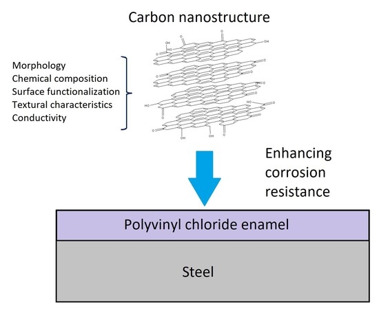
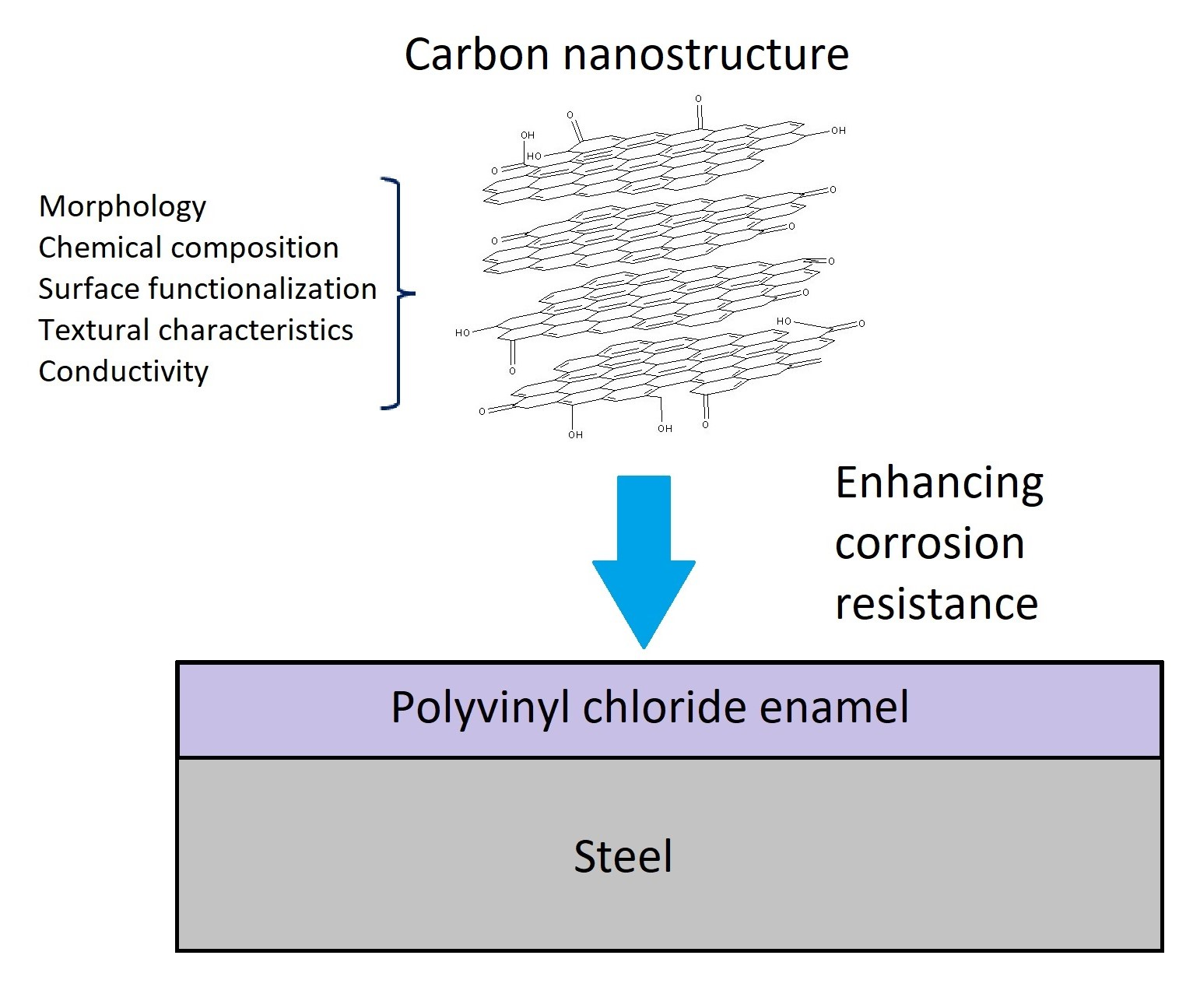
The article investigates the role of carbon nanomaterials (CNMs), surface-oxidized carbon nanotubes (CNTs) and few-layer graphene fragments (FGFs), as well as FGFs hetero-doped with N and P atoms, as anticorrosive additives in industrial paints based on polyvinyl chloride. All CNMs were characterized by thermogravimetry, transmission electron microscopy, low-temperature nitrogen adsorption, and X-ray photoelectron spectroscopy. Corrosion resistance was determined using electrochemical tests and impedance spectroscopy. The surface and internal 3D structure of steel and coated steel were visualized using laser confocal microscopy and computed tomography. Coatings containing polyvinyl chloride with 0.05 wt% oxidized CNTs or FGFs show the highest electrochemical resistance and the best anticorrosive properties. The corrosion rate for coatings containing CNMs decreases by an average of 5–7 times compared to uncoated steel. It is shown that the improvement in anticorrosive characteristics is determined by the texture parameters and the composition of CNMs. The pores in CNMs act as a reservoir for the electrolyte and increase the corrosion rate. Oxygen-containing surface groups prevent corrosion by increasing the resistance of the materials.

Graphical Abstract

1. Introduction

The corrosion and fouling of ship bottoms by living organisms are global problems that make their operation and maintenance expensive and environmentally unsafe [1]. To increase service life, reduce maintenance costs, and increase sailing speed, hull surfaces are coated with various coatings that reduce friction with water and prevent corrosion and fouling [2]. Metals, metal oxides, ceramic compositions, and organic compounds are used as coating materials [3]. Organic coatings are usually based on polymers such as polypyrrole [4], polyurethane [4,5,6], epoxy resins [7], polyaniline [8], acrylic polymers [9,10], polyvinyl chloride and its copolymers [11,12], and other compounds [13]. Cu(I), Ag, Au, Zn, Sn, Pb, Ce, Ti, As, and Cr compounds are also introduced into the polymer matrix, which increases the service life of the polymer coating due to their biocidal action and, as a result, reduces biocidal corrosion. However, these compounds are environmentally unsafe and limit the possible effects of surface self-restoration [14,15,16,17,18].
Recently, polymer coatings to which carbon nanomaterials (CNMs) are added, combining protection against corrosion, fouling, and rotting, have become of particular importance [18,19,20,21,22,23]. CNM–polymer composites form an effective insulating barrier due to their hydrophobicity and reduced diffusion rate of salt water to the metal [24,25,26,27]. CNMs adsorb oxygen molecules and radicals, OH, Cl, and SO42− ions on their surface, which leads to their decreased concentration in protective coatings and helps mitigate corrosion [28,29]. Theoretically, it has been shown that, in the most general case, the effectiveness of CNMs as an additive is determined (in order of decreasing effect) by their hydrophilicity, particle geometry (morphology), and active surface area [30].
Graphene stabilized with polybutylaniline in an epoxy resin [26], as well as graphene oxide modified with polyaniline [31] or polyvinylpyrrolidone [32], have been described as CNMs. CNTs are also described as fillers for polymer matrices made of polyurethane [33,34,35] or polyvinyl chloride [36,37]. Carbon quantum dots have been proposed for use in polyvinyl chloride compositions [38]. In all cases, such additives provided a significantly reduced (by 5–7 times) corrosion rate compared to coatings without CNMs in their compositions. Among heterosubstituted CNMs, N-doped graphene oxide and N-CNTs have been described as additives in coatings and enamels that reduce the corrosion rate by seven times [39].
CNMs as additives to polymer matrices also contribute to improving the tribological characteristics of coatings [40]. Nanoparticles, especially ones with a 0D structure, such as nanodiamonds, fullerenes, and carbon dots, fill the pores in the polymer structure, making the coatings monolithic [25]. In the case of 1D structures, such as CNTs, the polymers are reinforced, and the coating gains additional mechanical strength [40,41]. Graphene sheets have the ability to form a cross-linked graphene conductive network with bulk conductivity resulting in the displacing of cathodic oxygen reduction sites to graphene from the metal body [25,42]. CNM hydrophilicity is a crucial characteristic of carbon additives resulting in uniform distribution in the polymer. The hydrophilicity is achieved through oxidation or surface modification [43,44]. For example, An and their co-authors oxidized and then fluorinated graphene oxide surface to achieve the balance between anticorrosion and hydrophilic characteristics [45].
The purpose of the current research is to study the effect of the composition and morphology of carbon nanomaterials (surface-oxidized carbon nanotubes, multilayer graphene fragments, and heteroatomic N- and P-atom-doped FGFs) on the anticorrosive properties of composite coatings based on polyvinyl chloride paints.

2. Materials and Methods

2.1. Synthesis of Carbon Nanomaterials

Few-layer graphene fragments (FGFs), nitrogen- and phosphorus-doped FGFs (N-FGFs and P-FGFs, respectively), were obtained by hexane CVD (chemically pure, JSC Reahim, Moscow, Russia), acetonitrile (99.85%, LLC Component Reaktiv, Moscow, Russia), or PPh3 (98%, Sisco Res. Lab., Mumbai, India) in a toluene solution (99.5%, LLC Component Reaktiv, Moscow, Russia) in the presence of an MgO template at 900 °C, according to [46,47,48]. CNTs were synthesized by hexane CVD in the presence of a Co,Mo/MgO catalyst at 750 °C [49].
Quartz boats with an MgO template or a Co,Mo/MgO catalyst were placed in a tubular quartz reactor (55 mm diameter). N2 (99.999%, LLC Logika, Moscow, Russia) was purged, after which hexane, acetonitrile, or a PPh3 solution in toluene was passed through at the previously specified operating temperatures for 30 min. The reactor was then cooled in an N2 current to room temperature, and the resulting products were boiled with HCl (chemically pure, JSC Reakhim, Moscow, Russia) to remove MgO and dried at 110 °C for 10 h.
The surfaces of FGFs and CNTs were oxidized by boiling them under reflux in a solution of 69% HNO3 (extra pure 18-4, LLC Component-Reaktiv, Moscow, Russia) for 1.5 h for FGFs and 3 h for CNTs, after which they were filtered, rinsed with water to a neutral pH of the rinsing water, and dried at 110 °C for at least 10 h.

2.2. Physico-Chemical Analysis

The thermal stability of CNTs, the number of carbon phases, and the content of combustible impurities were evaluated using thermogravimetric (TG), differential thermal analysis (DTA), and differential scanning calorimetry (DSC) with a Netzsch STA 449 PC LUXX instrument (NETZSCH-Gerätebau GmbH, Selb, Germany). The samples were heated in atmospheric air from room temperature to 1000 °C at a rate of 10 °C·min−1.
Surface morphology and particle size were studied by transmission electron microscopy (TEM) using a JEOL 2100 F/Cs device (JEOL, Tokyo, Japan) at an operating voltage of 200 kV.
The composition of the CNM surface was determined by X-ray photoelectron spectroscopy (XPS) on an Axis Ultra DLD instrument (Kratos Analytical, Great Britain, Manchester, United Kingdom) using monochromatic AlKα radiation (1486.7 eV). The survey XPS spectra were obtained with an analyzer transmission energy of 160 eV and a step of 1 eV, and the high-resolution spectra were obtained with a transmission energy of 40 eV and a step of 0.1 eV.
Low-temperature adsorption–desorption isotherms were obtained using an Autosorb-1C/QMS device (Quantachrome Inc., Boynton Beach, USA). The BJH model [50] was used to calculate the specific surface area SBET and the pore size distribution. The samples were evacuated at 300 °C for 3 h before the measurements, after which the measurements were carried out.

2.3. Preparation and Coating of Steel Samples

CNM samples (0.05 wt%) were weighed and mixed with a commercially available vinyl chloride copolymer enamel of the HS–5226 brand (LLC NTC Spetsmal, St. Petersburg, Russia). The mixtures were placed in a glass reactor equipped with an external cooling jacket and treated with ultrasound (IL10-0.63 ultrasound generator, Inlab Ltd., Russia) for 3.5 h. The enamels modified in this way were applied using brushes, followed by leveling the layer with a crossbar to a specified thickness of 100 µm on PCA steel plates (PJSC Novolipetsk Metallurgical Combine, Lipetsk, Russia) measuring 100 × 135 × 4 mm in size. For comparison, HS–5226 enamel without CNMs was applied, forming coatings 50 and 100 µm thick. Before coating, the surface of the plates was sanded with sandpaper and wiped with alcohol. The applied enamel was dried at room temperature for 24 h. The thickness of the coating layer was additionally monitored using an RGK MC-25 micrometer (RGK JSC, Moscow, Russia).

2.4. Electrochemical Measurements

Electrochemical tests were performed in 50 mL three-electrode glass electrochemical cells. A 3.5 wt% NaCl solution in distilled water, simulating seawater, was used as the electrolyte. The working electrode consisted of coated steel plates, the counter electrode was Pt, and the reference electrode was a silver–silver chloride electrode. The area of the working and Pt electrodes was 1 cm2. All tests were performed at room temperature.
A Biologic VSP potentiostat/galvanostat (BioLogic Science Instruments, Seyssinet-Pariset, France) was used to measure the voltage characteristics of materials, electrode polarization, and impedance spectroscopy. For corrosion monitoring, the linear polarization resistance method was used, specifically designed to determine the polarization resistance of a material and the corrosion current when passing through potential steps around the corrosion potential. During this procedure, the open-circuit potential (OC) Eoc of the sample was measured for 5–55 min to ensure system stability, determined by an Eoc drift of no more than 2 mV h−1. The sample was then polarized to −30 mV relative to Eoc for 1 min. After that, the potential was scanned from −30 mV to 30 mV relative to Eoc at a rate of 0.1 mV s−1. The values of Rp, Ecorr, and icorr were determined using EC-Lab 11.61 software (BioLogic Science Instruments, Seyssinet-Pariset, France).
Before recording the Tafelian curves, the Eoc value was continuously measured until its drift did not exceed 2 mV·s−1. Next, the curve was recorded in the linear potential scanning mode in the range from −250 mV to 250 mV relative to Eoc at a scanning rate of 0.1 mV s−1. The values of Ecorr, icorr, coefficients ba, bc, and corrosion rate were determined using EC-Lab 11.61 software.
Impedance measurements were carried out with a potential amplitude of ±10 mV, 1–10 weeks after the coating was impregnated with 3.5 wt% NaCl, in the frequency range from 50 × 10−3 to 106 Hz. The data obtained were processed using OriginPro 2021 software (OriginLab Corporation, Northampton, USA).

2.5. Visualization of Coating Corrosion by Confocal Microscopy and Computed Tomography

Surface visualization before and after electrochemical corrosion etching was performed using an OLYMPUS LEXT OLS-3000 laser confocal microscope (Ryokosha, Ltd., Tokyo, Japan).
Additionally, steel plate samples 2 mm thick were prepared for tomography. The coatings were applied similarly to the method described above. Corrosion was induced by holding these plates for 4 weeks in a 3.5 wt% NaCl solution at room temperature.
Three-dimensional visualization of corrosion of steel plates was performed by computed tomography using an energy-sensitive MARS Bioimaging CT scanner (MARS Bioimaging Ltd., Christchurch, New Zealand) with semiconductor hybrid pixel detectors Medipix3RX (Medipix3 Collaboration, Geneva, Switzerland) with CdZnTe sensors 1 mm thick. Scanning was performed with a tube voltage of 120 kV, a current of 40 µA, an exposure time of 100 ms, an energy threshold of 30 keV, and a projection step of 0.5° (720 projections per revolution). During scanning, constant temperature conditions were maintained, with the detector temperature not exceeding 16 °C. Reconstruction was carried out for an energy window of 30–120 keV with a voxel size of 0.06 mm. The reconstructions were visualized using MARS Vision 2.0 software (MARS Bioimaging Ltd., Christchurch, New Zealand). At least four plates of each type were examined to obtain statistically acceptable results.

3. Results

3.1. Physical and Chemical Characteristics of Carbon Nanomaterials

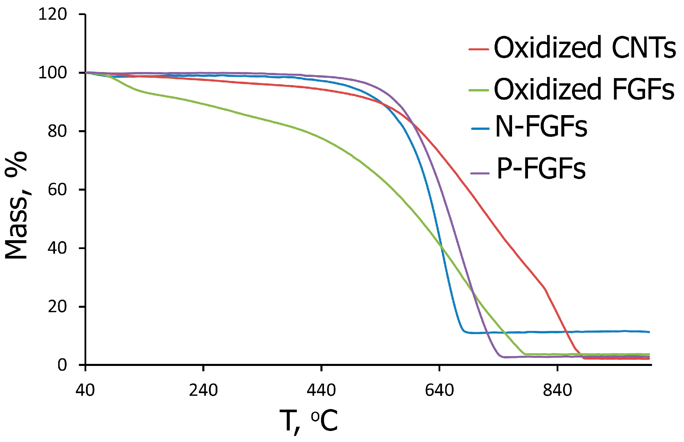
The carbon phase content in the synthesized CNMs was confirmed by the TG method. In oxidized CNTs, oxidized FGFs, N-FGFs, and P-FGFs, the content of combustible impurities was 2.9, 3.7, 11.5, and 2.8 wt%, respectively (Figure 1).
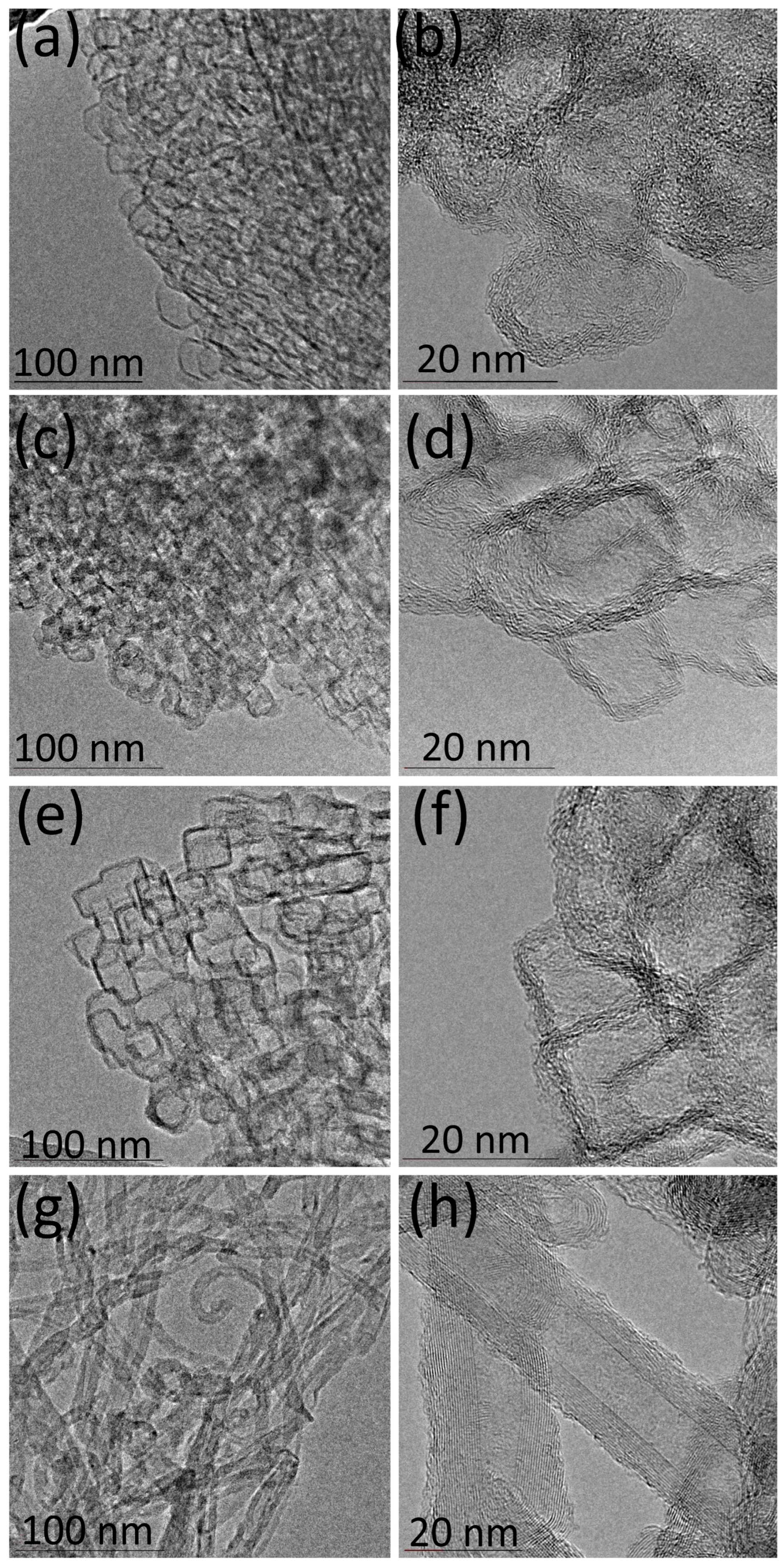
According to the TEM data, particles of oxidized FGFs, N-FGFs, and P-FGFs are two-dimensional polyhedra consisting of several stacked graphene layers (Figure 2a–f). Oxidized CNMs are multi-walled tubes with an outer diameter of 15 nm and 12–15 carbon layers (Figure 2g,h).
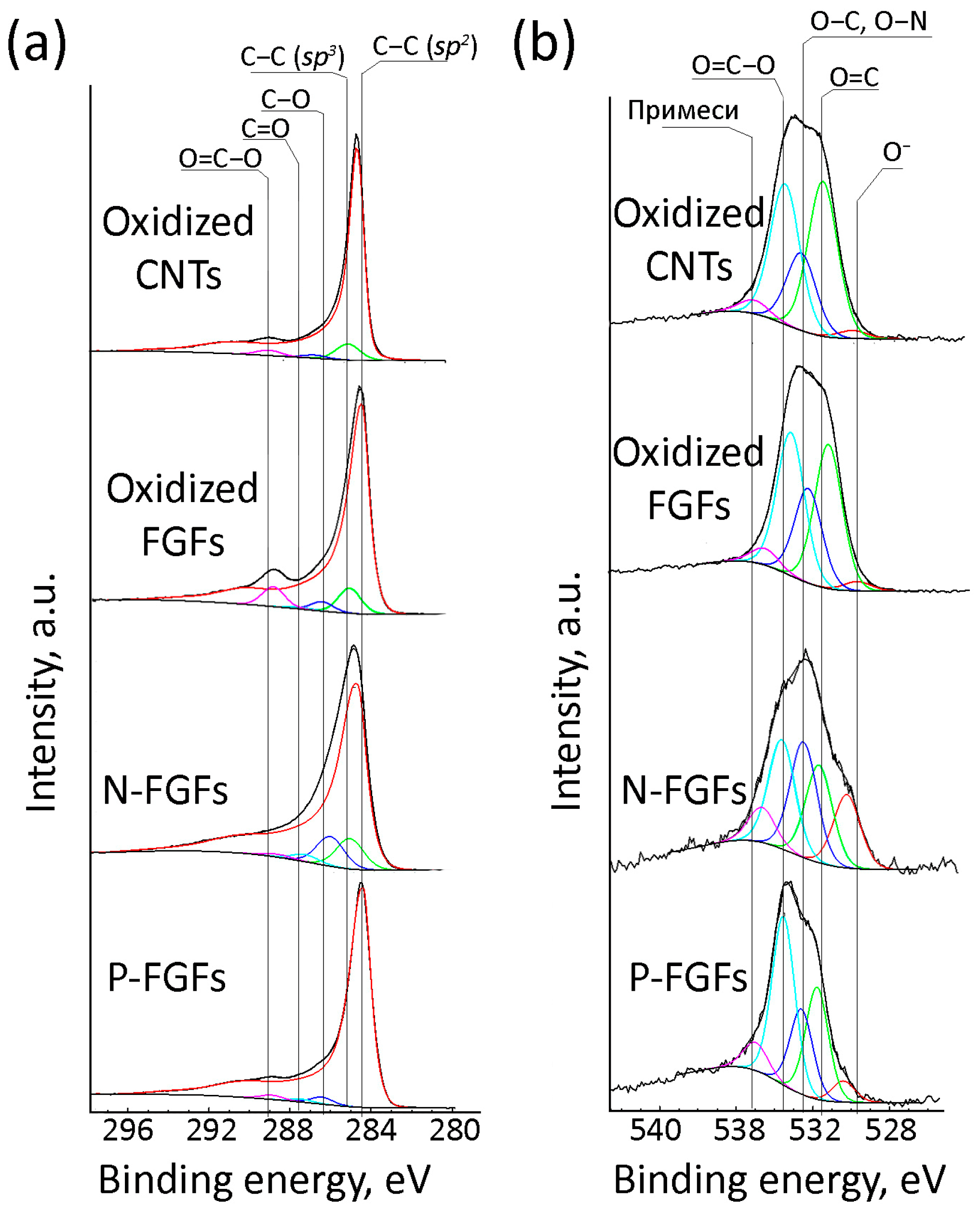
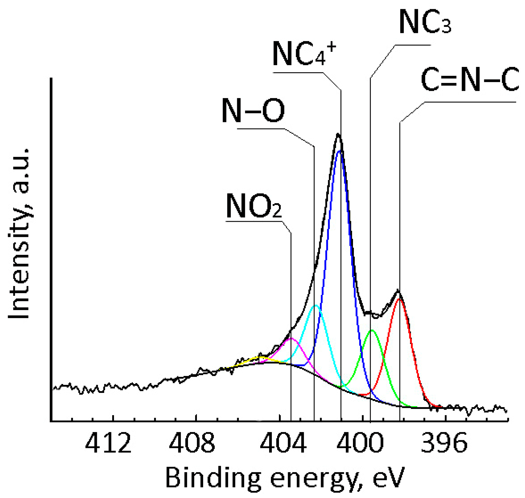
The surface composition of the obtained CNMs was determined by the XPS (Table 1). In the high-resolution C1s XPS spectra, maxima corresponding to the C–C bond energies in the sp 2 (284.9 eV) and sp 3 (285.2 eV) hybridized states, C–O (286.2 eV), C=O (287.4), and O=C–O (288.8) can be distinguished (Figure 3a). High-resolution O1s XPS spectra contain maxima corresponding to oxygen in the O (530.2 eV) state, as part of O=C (531.6 eV), O–C, and O–N (532.4 eV) bonds, O=C–O as part of carboxyl groups (533.5 eV), and non-conductive impurities (534.5) (Figure 3b). The high-resolution N1s XPS spectrum of N-FGFs contains maxima corresponding to nitrogen atoms in the pyridine-like state C=N–C (398.2 eV), in amino groups NC3 (399.5 eV), the substitution state (401.1 eV), NC4+ (402.2 eV), as well as nitrogen bound to oxygen atoms N–O (403.4 eV) and NO2 (405.0) (Figure 4).
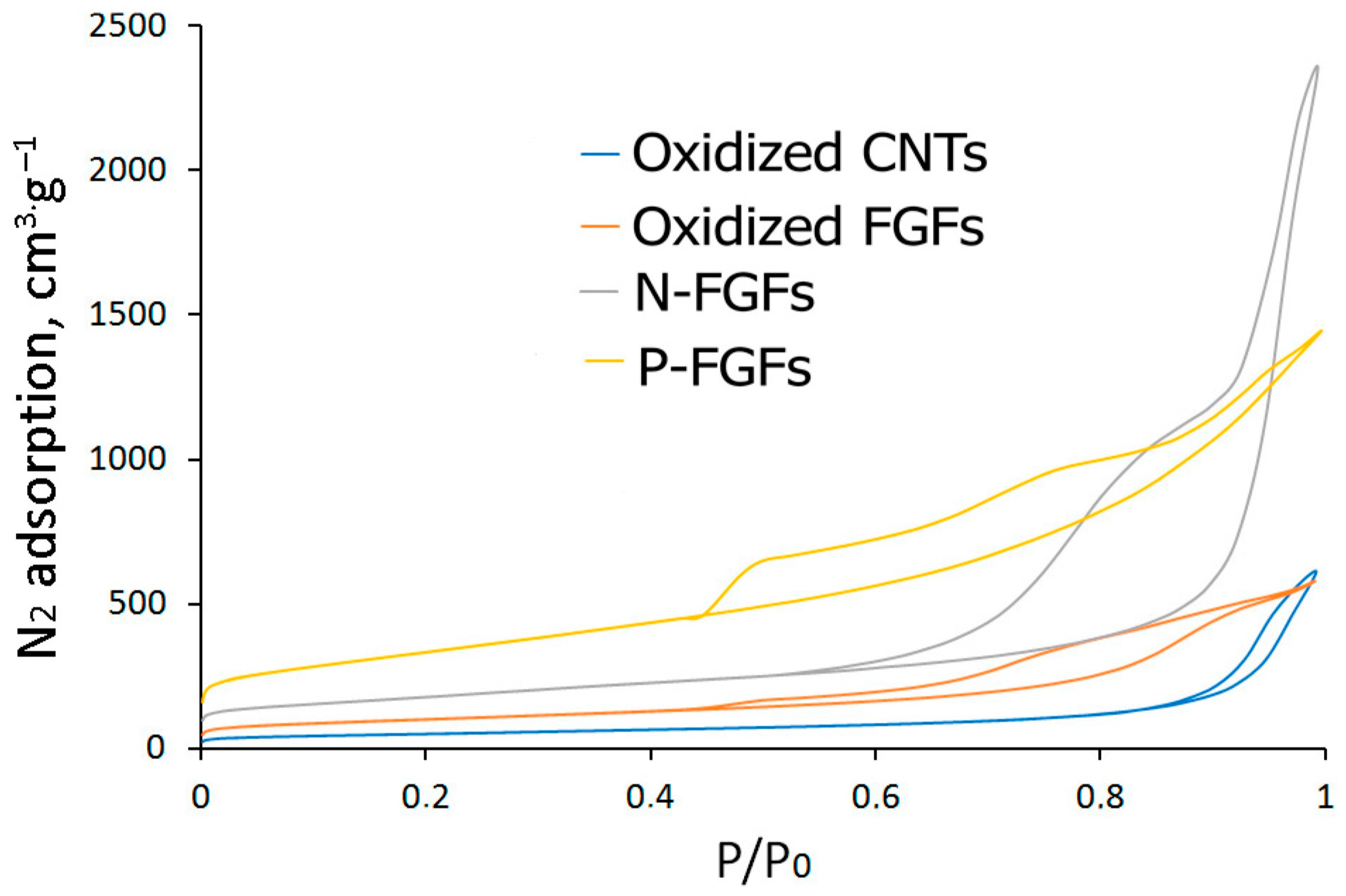
The low-temperature adsorption–desorption isotherms of all CNMs belong to type II (Figure 5), and the materials contain mesopores, according to the IUPAC classification [50]. The pore parameters and specific surface area values are shown in Table 1.

3.2. Anticorrosive Resistance of Coatings

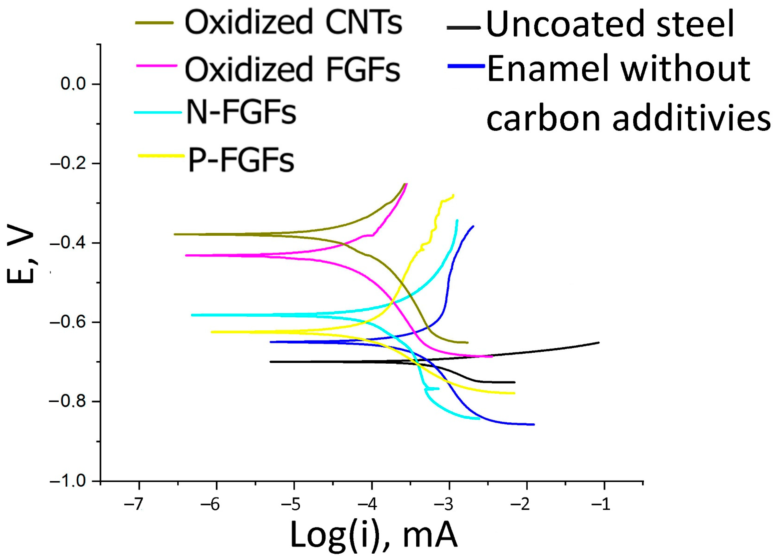
Tafel curves showing the correlation between the overvoltage at the cathode and anode and lg(i) are given in Figure 6.
The corrosion current density (Table 2) was determined graphically by the intersection of the lines obtained by extrapolating the linear regions of the cathode and anode dependencies n = f(i) with the corrosion potential, the point where the overvoltage is zero (Figure S1, Supplementary Materials). Taking into account the well-known Tafel equation:
ηa(c) = a + ba(c) lg(ia(c)),
where ηa(c) is the overvoltage at the anode or cathode, expressed in volts, ia(c) is the current at the electrode, expressed in amperes, a is the Tafel constant; ba(c) is the anode or cathode Tafel coefficient [51], the values of the coefficients ba(c) were determined (Table 2).
The polarization resistance was calculated using the equation (Table 2):
R p = 1 d i d E ,
where
i = i c o r r . ( e x p ( l n 10 ( E E c o r r . ) b α e x p ( l n 10 ( E E c o r r . ) b β )
If E = Ecorr., then Expression (3) is reduced to the well-known Stern–Geary equation:
i c o r r . = b a b c 2.303 b a + b c R p ,
where ba(c) is the anode or cathode Tafel coefficient, determined by Equation (1), and Rp is the polarization resistance. The polarization resistance Rp was calculated as the coefficient of proportionality between current i and voltage E for small values of E (Table 2).
The values of Ecorr. and icorr. obtained from Equations (1) and (4) are different (Table 2), which is consistent with the data [37].
The corrosion rate was calculated using the equation:
C o r r o s i o n   R a t e = 0.13 i c o r r . ( E . W . ) A d ,
where icorr. is the corrosion current expressed in amperes, E.W. is the equivalent weight equal to 28 g∙equation−1, A is the area equal to 1 cm2, and d is the density of steel equal to 7.800 g∙cm−3.
The effectiveness of coatings (Table 2) was estimated using the equation:
P   =   ( 1   i c o r r . i c o r r . )   100 ,
where icorr. is the corrosion current of steel, i’corr. is the corrosion current of steel coated with a film of enamel grade HS–5226 or enamel grade HS–5226 with 0.05 wt% CNMs.

3.3. Impedance Spectroscopy

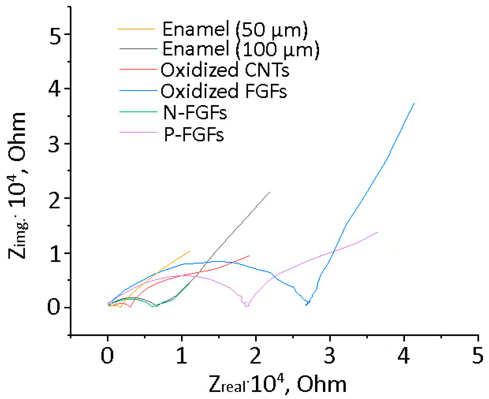
Impedance spectroscopy is a universal method for examining the metal–coating, metal–electrolyte, and similar interfaces. Experimental impedance hodographs of the obtained coatings are shown in Figure 7.
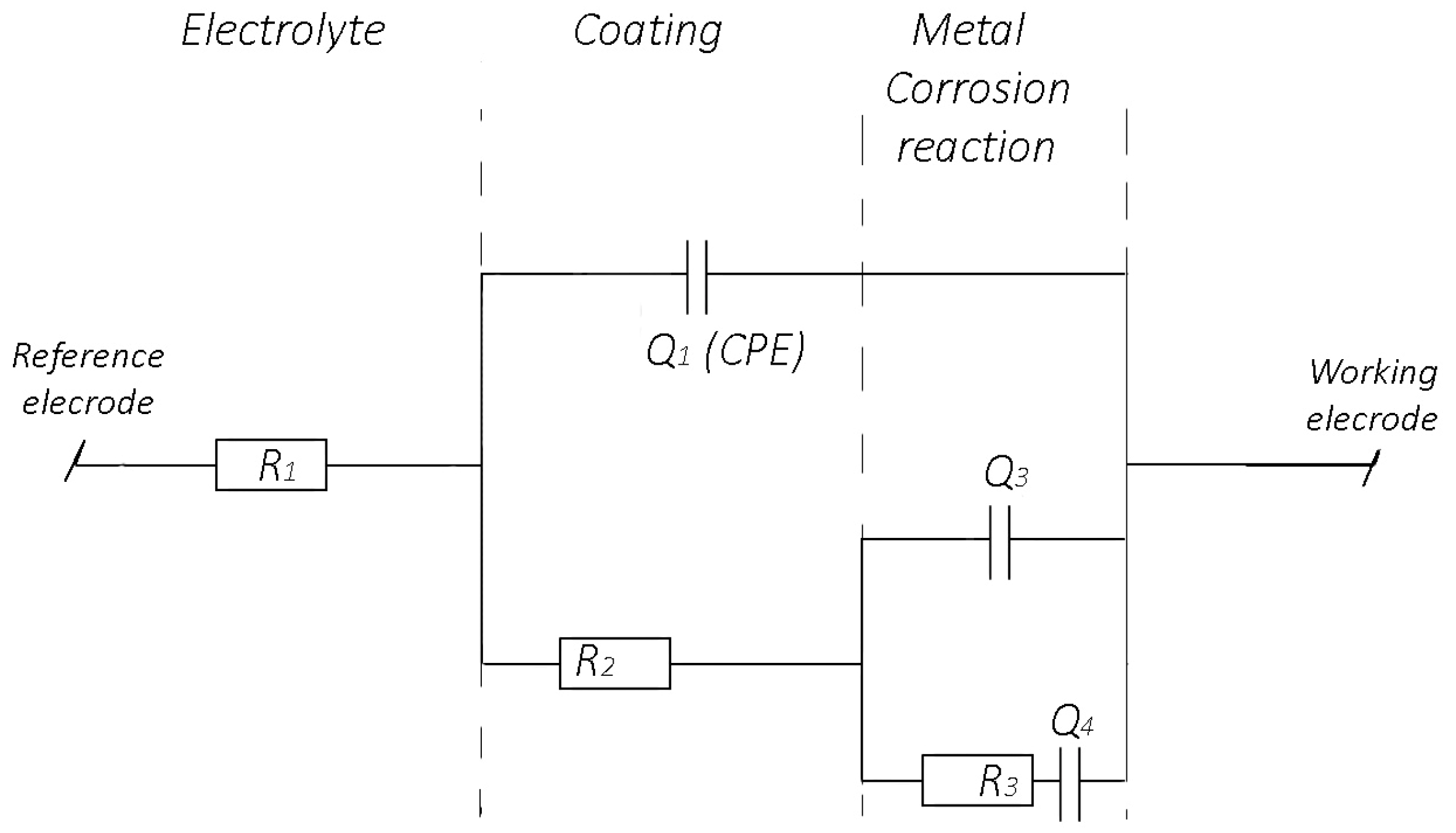
In the most general case, to study the corrosion of steel plates coated with paints and enamels, calculations were carried out using an equivalent circuit (Figure 8) [52,53,54], taking into account the resistive (R1) and capacitive (Q1, constant phase element, CPE) layer parameters. Resistance R2 refers to pore resistance, while resistance R3 and capacitance Q3 (Warburg element) characterize the kinetics of the process associated with the diffusion of the electrolyte to the steel surface. The hodograph can be described by the equation:
Z = 1 A ( j ω ) α ,
where A is a preexponential multiplier, which is a frequency–independent parameter, α is an exponent that determines the nature of the frequency dependence (−1 ≤ α ≤ 1), and j = −1 is an imaginary unit.
When calculating the corresponding equivalent scheme for each coating, it was found that it satisfactorily describes the hodographs of all coatings, except for the 50 µm coating sample without CNM additives (Figure S2, Supplementary Materials). Based on these models, the parameters R1, R2, R3, Q1, Q3, Q4 and α1, α3, α4 for each coating were calculated (Table 3).

4. Discussion

Seawater is an electrolyte due to the salts and oxygen dissolved in it (~8 mg/L), which contribute to the oxidation of steel surfaces, resulting in the formation of rust, oxides, hydroxides, and oxyhydroxide derivatives of iron of variable composition, FeO·Fe2O3·nH2O. Chloride ions destroy and prevent the formation of passivating films of FeO·Fe2O3·nH2O on the metal surface. Applied polymer coatings protect the steel surface from direct interaction with oxygen, water, and salt ions dissolved in water. Uneven or imperfect coatings, as well as possible chipping and damage due to temperature fluctuations, lead to the development of corrosion. Another possible cause of corrosion under a continuous coating layer is the ability of water, oxygen molecules, and electrolyte ions to diffuse through the coating and eventually reach the steel surface [55].
In the most general case, the dissolution of Fe occurs, according to the equation:
Fe0 – 2e  Fe2+
with simultaneous reduction of oxygen atoms dissolved in water:
O2 + 2H2O + 4e  4OH
At high external potentials, hydrogen gas is released under electrochemical testing conditions:
2H+ + 2e  H2
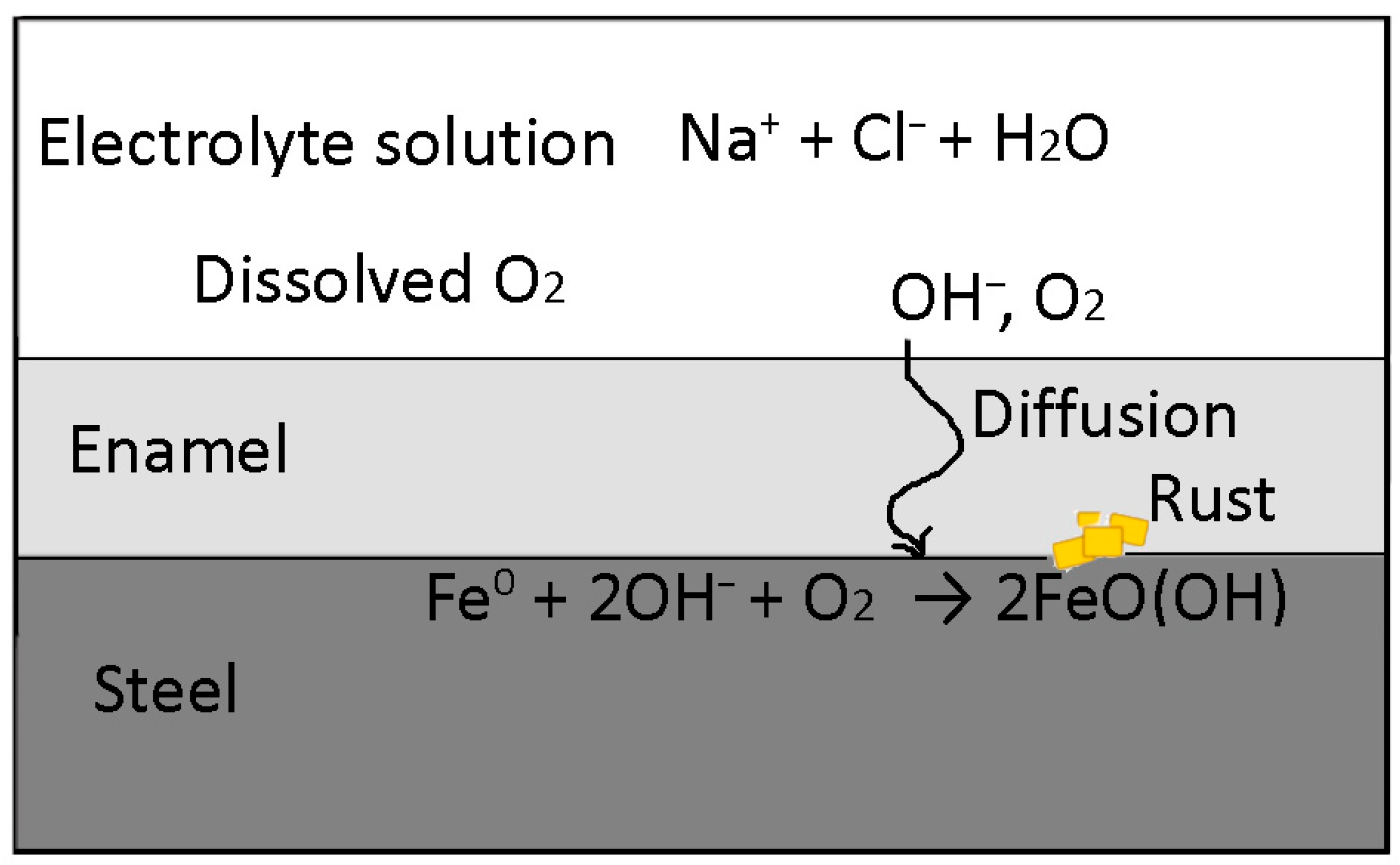
The reaction products of Fe2+ and OH, according to Equations (8) and (9), then diffuse back through the coating layer (Figure 9).
For an anticorrosive coating, good adhesion to the steel surface is crucial, since otherwise water and reaction products (7)–(9) can accumulate under the coating, violating the integrity of the interfacial boundary. In extreme cases, bubbles form, leading to peeling and cracking in the coating.
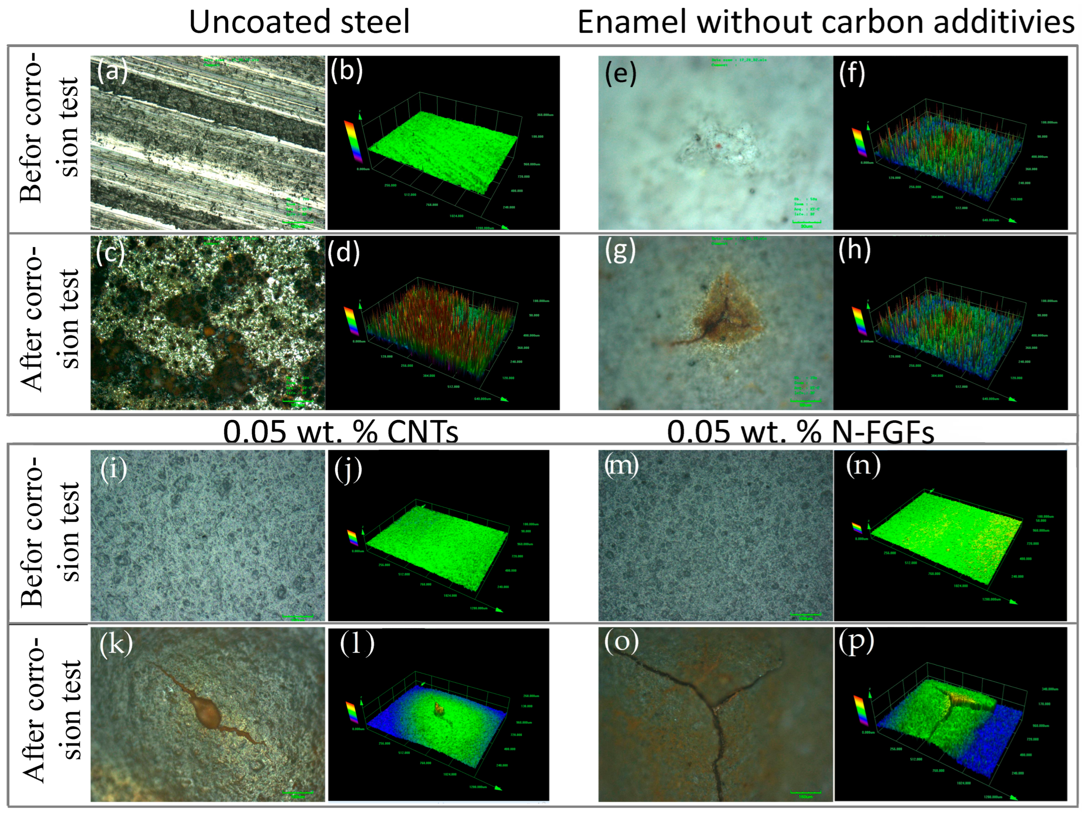
The nature of damage and corrosion in this study was investigated using optical and tomographic methods. Optical and 3D confocal images of the surface of coating samples after electrochemical corrosion tests are shown in Figure 10. Traces of surface grinding are clearly visible on the steel surface (Figure 10a), which do not practically change the height of the steel plate (Figure 10b). After corrosion tests, crater-like defects appeared on the surface—pitting corrosion (Figure 10c,d), associated with the dissolution of Fe, as well as the formation of rust. When steel is coated with films of polyvinyl chloride and/or polyvinyl chloride with CNMs, surface degradation and rust spots occur to a much lesser extent (Figure 10e–p). The morphology and nature of the damage differ from those of unprotected steel. It is likely that electrochemical oxidation products accumulate under the films according to Equations (7)–(9), resulting in swelling and rupture accompanied by cracking of the coating (Figure 10g,k,o). As a result, the electrolyte solution becomes freely accessible to the steel surface, and corrosion develops over the entire damaged area of the coating. It should be noted that the formation of crater-like defects in coatings was previously observed for a large number of polymers and polymer composites with CNMs, as confirmed by scanning electron microscopy [39], confocal microscopy [56], etc.
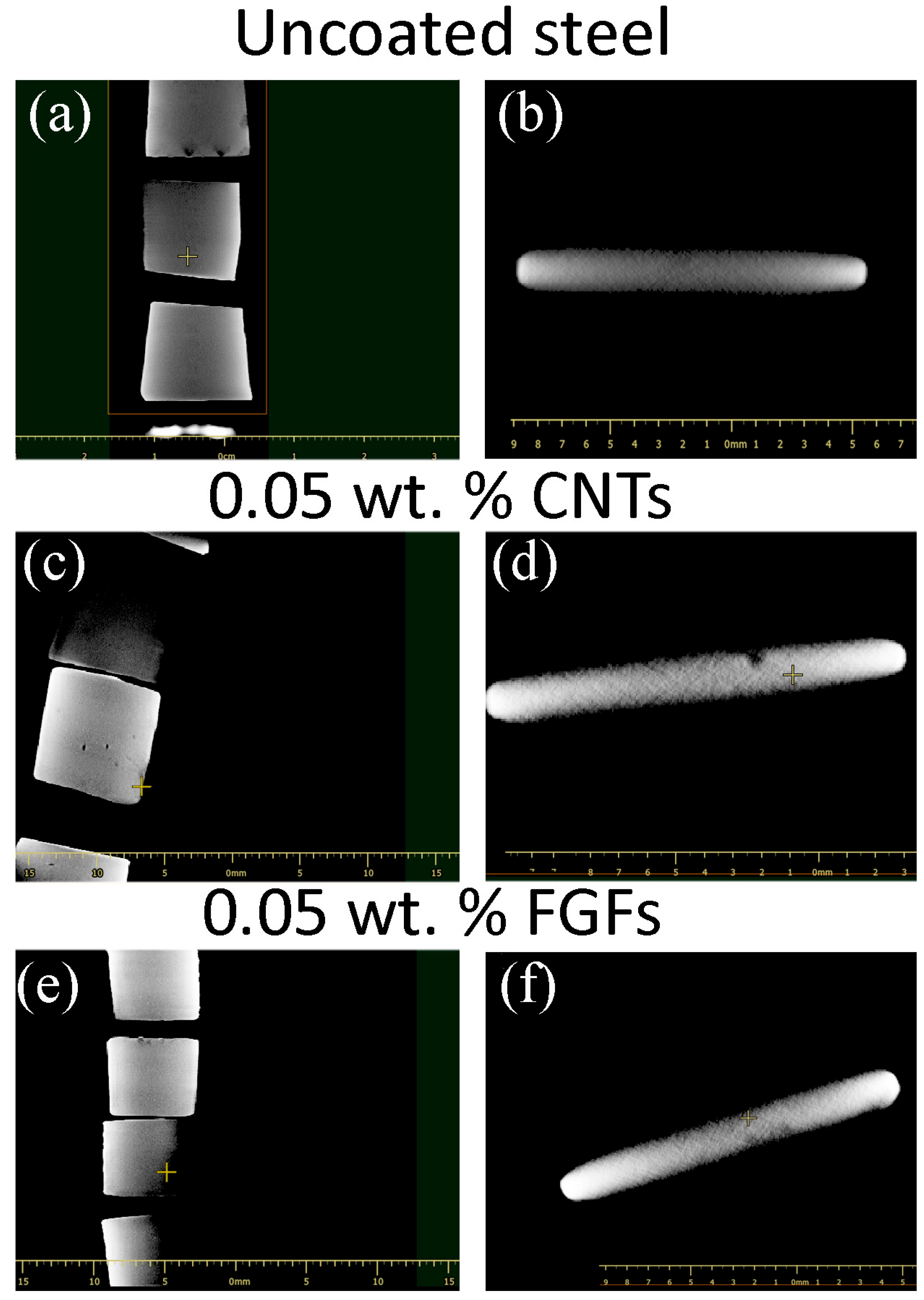
Similar results were obtained when visualizing corrosion using computed tomography (Figure 11). There were no distinct signs of corrosion on the tomograms of uncoated steel, presumably due to the superficial nature of the process, which did not lead to the formation of localized defects detectable by tomographic methods (Figure 11a,b). In corroded steel samples coated with 0.05 wt% oxidized CNTs, the formation of deep crater-like defects up to 0.5–1 mm in depth was observed, corresponding to a pitting corrosion process (Figure 11c,d). For enameled steel with the addition of 0.05 wt% N-FGFs, the formation of crater-like defects was also observed, but with smaller dimensions and depth (Figure 11e,f).
When water diffuses into the coating, its conductivity changes [36]. It has been experimentally found that the better the coating conducts electric current, the worse its anticorrosive properties [57].
In this paper, the conductivity of coatings was investigated by impedance spectroscopy. The samples were kept in a 3.5 wt% NaCl solution, and the films were completely impregnated for several days up to ~10 weeks, after which the conductivity was measured. Uncoated steel is a conductive material: there is only one semicircle on the impedance hodograph (Figure 7), and the corrosion rate is maximal at 6.202 mm·year−1 (Table 2).
For polymer samples with CNMs, two insufficiently pronounced semicircles with frequency-independent parameters can be distinguished on the impedance hodographs (Figure 7 and Figure S2). This pattern is typical for layered structures, in which two or more interphase boundaries can be distinguished. In this case, these are the electrolyte coating (resistance Q1 in Figure 8) and steel coating (resistance Q3). The load Q4, whose contribution is small, can be attributed to possible inhomogeneities in the film structure associated with the presence of CNM particles in the polymer film and the appearance of resistance at the polymer/CNM interface. The physical meaning of the observed hodographs lies in the fact that at low frequencies, OH ions diffuse to the steel electrode through the film and then deposit on it with charge transfer to an external circuit [55].
To evaluate the effectiveness of the coating in terms of forming a double electric layer, it is necessary to compare the values of the exponent α, which is the argument of the function Z in Equation (5). In this paper, the exponent of α1, corresponding to the electrolyte/coating interface, varies from 0.49 to 0.71 (Table 3), which indicates the Warburg diffusion resistance of the element Q1. When considering the coating/steel interface, only coatings with 0.05 wt% oxidized CNTs showed an α3 value of 1, which corresponds to an «ideal supercapacitor» [58]. It is for this coating that one of the lowest corrosion rates was found, equal to 0.998 × 10⁻³ mm·year−1 (Table 2).
The Tafel curves for all examined materials are shown in Figure 8. The appearance of all the obtained curves is typical for electrochemical processes during metal corrosion in marine conditions. The more positive the open-circuit potential, the better the corrosion process is inhibited, as previously shown for the addition of silanes to epoxy resins [59]. The highest value of Ecorr. = −388.5 mV is typical for a coating without the addition of CNMs (Figure 8, Table 2). Depending on the additive to the polymer coating, the potential Ecorr increases in the following range: coating without additives ~ N-FGFs > P-FGFs ~ oxidized CNTs > oxidized FGFs. Accordingly, the current and the corrosion rate decrease in the same order.
To substantiate the effect of CNMs on the anticorrosive properties of coatings, it is necessary to take into account their composition and morphology. Oxidation of the surface of CNMs, as a rule, leads to better dispersibility in polymer compositions [60], although, in general, dispersion of CNM particles in a PVC matrix under ultrasound is a commonly accepted technique leading to positive results [61].
It is known that polyvinyl chloride has a highly organized structure; the introduction of CNMs into its composition promotes reorganization such that the CNMs are not randomly distributed in the polymer [62,63]. The improvement of material properties is achieved due to the strong influence of the developed CNM surface on the ordering of elements in systems with a randomly formed structure. This occurs due to the formation of covalent bonds between CNMs and the polymer [22,39] or due to interactions via van der Waals forces [64].
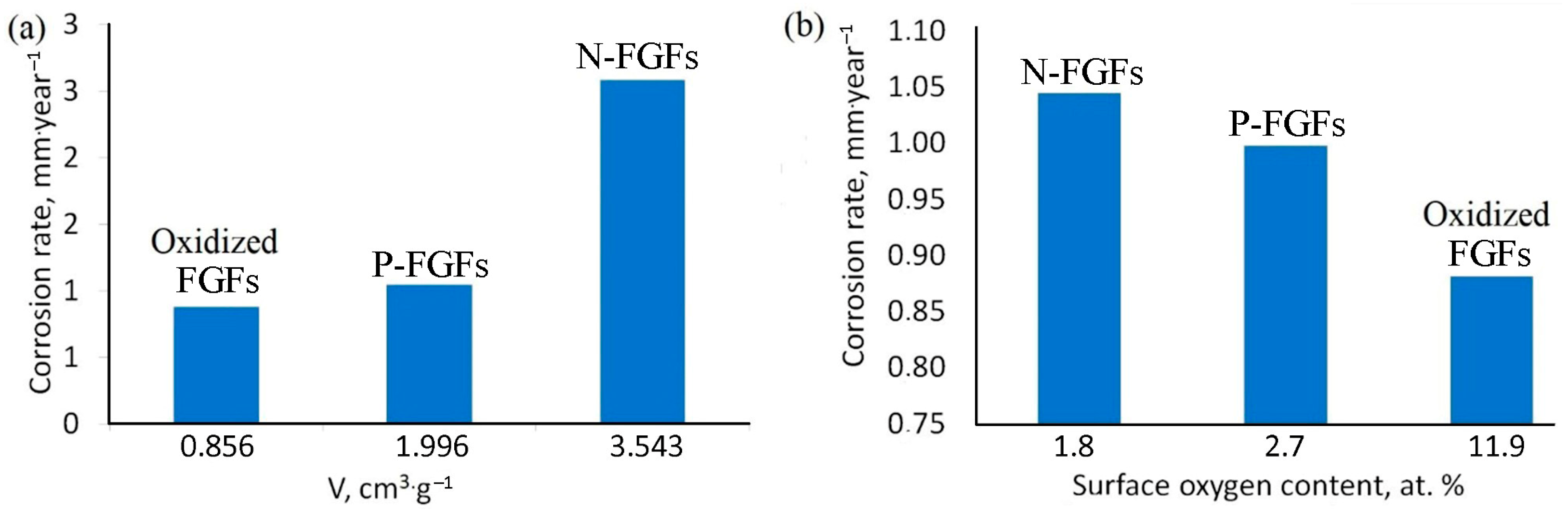
In this paper, the introduction of surface-oxidized FGFs led to the most significant improvement in anticorrosive properties, which is probably determined by a combination of the textural characteristics of FGFs and the presence of oxygen-containing surface groups (Figure 12). It is well-known that graphene particles occupy pores in the polymer, which typically reduces the water diffusion into the composite volume [25,65]. As the pore volume Vpore in the CNM structure increases, the corrosion rate also increases (Figure 12a). The pores probably act as a reservoir for the electrolyte solution and contribute to its diffusion to the steel surface. At the same time, the corrosion rate decreases with increasing content of surface groups (Figure 12b). Oxygen-containing surface groups improve the adhesion of polymer-CNM composites to steel [66] and reduce the conductivity of both CNMs [67] and the composites containing them [63,68].

5. Conclusions

The development of anticorrosion additives has gone beyond the laboratory and become a routine practice. Currently, majority of paint and enamel manufacturers use CNMs as additives [69,70]. The anticorrosive properties of coatings based on commercially available polyvinyl chloride paints can be significantly improved by adding CNMs. In particular, surface-oxidized CNTs and FGFs, as well as FGFs hetero-doped with N and P atoms, introduced in an amount of 0.05 wt%, reduced the corrosion rate of steel by 5–7 times compared to the uncoated surface.
Impedance spectroscopy showed that, in the most general case, the coating contributes to the formation of two interfaces: electrolyte/coating and coating/steel. The highest resistance and, as a result, the lowest corrosion rate were observed for the coating with 0.05 wt% surface-oxidized CNTs. Oxygen-containing surface groups contribute to a decrease in the conductivity of CNMs and polyvinyl chloride/CNM composites in general. Heteroatoms in FGFs lead to the formation of different numbers of surface groups; therefore, samples with a higher content of surface groups are the most effective anticorrosive additives. In addition to surface modification, the porosity of the CNMs itself is critically important. These pores act as a reservoir for water and may contribute to corrosion. Therefore, we recommend choosing CNMs with micropores.

Supplementary Materials

The following supporting information can be downloaded at: https://www.mdpi.com/article/10.3390/cmd7030043/s1, Figure S1: Extrapolation of the linear regions of the cathode and anode Tafel curves of (a) uncoated steel, (b) steel with an enamel coating, (c) enamel containing 0.05 wt. % CNTs, (d) enamel containing 0.05 wt. % FGF, (e) enamel containing 0.05 wt. % N-FGF, (f) enamel containing 0.05 wt. % P-FGF.; Figure S2: Nyquist diagrams for the studied systems (black) and calculated curves (red) based on the proposed models.

Author Contributions

Conceptualization, E.V.S., S.V.Y., A.S.I. and D.N.S.; Methodology, S.V.Y., D.N.S., A.S.I. and D.A.S.; Formal Analysis, A.S.I. and D.A.S.; Investigation, A.S.I., D.N.S. and D.A.S.; Resources, S.V.Y. and S.V.S.; Data Curation, S.V.Y. and A.S.I.; Writing—Original Draft Preparation, E.V.S.; Writing—Review and Editing, E.V.S. and A.S.I.; Visualization, E.V.S., A.S.I. and D.A.S.; Supervision, S.V.S.; Project Administration, S.V.Y. and S.V.S. All authors have read and agreed to the published version of the manuscript.

Funding

The research was funded through the state assignment of Ministry of Science and Higher Education of the Russian Federation (AAAA-A21-121011990019-4).

Data Availability Statement

The data presented in this study are available on request from the corresponding author.

Acknowledgments

The authors express their acknowledgments to S.V. Maximov and K.I. Maslakov for their help in obtaining TEM images and XPS spectra, respectively. The work was performed using equipment purchased under the Moscow University Development Program.

Conflicts of Interest

The authors declare no conflicts of interest.

Abbreviations

The following abbreviations are used in this manuscript:
CNMscarbon nanomaterials
CNTscarbon nanotubes
DTAdifferential thermal analysis
DSCdifferential scanning calorimetry
FGFsfew-layer graphene fragments
OCopen-circuit (potential)
TEMtransmission electron microscopy
TGthermogravimetric
XPSX-ray photoelectron spectroscopy

References

  1. Kassinis, C.; Aresti, L.; Koronides, M.; Christodoulides, P.; Michailides, C.; Onoufriou, T. A review on the environment’s influence on coastal marine steel corrosion and in-situ monitoring. J. Mater. Sci. Mater. Eng. 2025, 20, 125. [Google Scholar] [CrossRef]
  2. Mosunov, A.A.; Mutovkin, P.A.; Velyaev, Y.O.; Degtyar, A.D. Obtaining hybrid polymer matrixes for the creation of antifouling coatings and studying their physical and mechanical properties. Trans. Kola Sci. Cent. Russ. Acad. Sci. 2024, 15, 302. [Google Scholar] [CrossRef]
  3. Kontus, O.; Kotta, J. Sustainable marine coatings: Comparing the costs, benefits, and impacts of biocidal and biocide-free paints. Coatings 2025, 15, 931. [Google Scholar] [CrossRef]
  4. Cai, Z.; Li, C.; Zhang, D.; Li, J.; Gao, L. An anti-corrosion coating with self-healing function of polyurethane modified by lipoic acid. J. Coat. Technol. Res. 2023, 20, 713. [Google Scholar] [CrossRef]
  5. Wang, L.; Wang, X.; Liu, T.; Sun, F.; Li, S.; Geng, Y.; Yao, B.W.; Xu, J.; Fu, J. Bio-inspired self-healing and anti-corrosion waterborne polyurethane coatings based on highly oriented graphene oxide. npj Mater. Degrad. 2023, 7, 96. [Google Scholar] [CrossRef]
  6. Hu, J.; Tian, S.; Li, R.; Lu, G.; Wang, N. A review on polyurethane anti-fouling coatings. Corros. Commun. 2025, 20, 53. [Google Scholar] [CrossRef]
  7. Verma, C.; Olasunkanmi, L.O.; Akpan, E.D.; Quraishi, M.A.; Dagdag, O.; El Gouri, M.; Sherif, E.S.M.; Ebenso, E.E. Epoxy resins as anticorrosive polymeric materials: A review. React. Funct. Polym. 2020, 156, 104741. [Google Scholar] [CrossRef]
  8. Xu, Z.; Yu, H.; Fang, T.; Zhang, M.; Liu, J.; Tan, X. Preparation and anticorrosion performance of nano polyaniline/polyurethane interpenetrating network composite coating. Polym. Int. 2024, 73, 130. [Google Scholar] [CrossRef]
  9. Zhou, H.; Lu, Q.; Su, Z.; Zhou, A.; Chen, X.; Zhang, B.; Qi, F.; Zhao, N.; Ouyang, X. Study on anticorrosive and self-healing properties of acrylic resin modified with nitrogen-doped carbon quantum dots. Chem. Eng. J. 2024, 494, 153165. [Google Scholar] [CrossRef]
  10. Liu, X.; Zhang, Y.; Jiang, Y.; Li, M.; Bai, J.; Zhou, X. Effect of Acrylic Resin on the Protection Performance of Epoxy Coating for Magnesium Alloy. Coatings 2024, 14, 577. [Google Scholar] [CrossRef]
  11. Liu, W.; Zhang, Y.; Fang, L.; Zhu, B.; Zhu, L. Antifouling properties of poly(vinyl chloride) membranes modified by amphiphilic copolymers P(MMA-b-MAA). Chin. J. Polym. Sci. 2012, 30, 568. [Google Scholar] [CrossRef]
  12. Fang, L.F.; Matsuyama, H.; Zhu, B.K.; Zhao, S. Development of antifouling poly(vinyl chloride) blend membranes by atom transfer radical polymerization. J. Appl. Polym. Sci. 2017, 135, 45832. [Google Scholar] [CrossRef]
  13. Ayaz, M.; Suleiman, G.S.A.; Altaf, M.; Zafar, A.M.; Cheng, X.; Feng, Y. Polymer and eco-friendly inhibitors for corrosion protection of reinforced concrete: A comprehensive review. J. Build. Eng. 2026, 119, 115119. [Google Scholar] [CrossRef]
  14. Figueiredo, J.; Loureiro, S.; Matrins, R. Hazard of novel anti-fouling nanomaterials and biocides DCOIT and silver to marine organisms. Environ. Sci. Nano 2020, 7, 1670. [Google Scholar] [CrossRef]
  15. Ali, A.; Jamil, M.I.; Jiang, J.; Shoaib, M.; Amin, B.U.; Luo, S.; Zhan, X.; Chen, F.; Zhang, Q. An overview of controlled-biocide-release coating based on polymer resin for marine antifouling applications. J. Polym. Res. 2020, 27, 85. [Google Scholar] [CrossRef]
  16. Ranjbar, Z.; Pourhadadi, D.; Montazeri, S.; Modaberi, M.R. Lead compounds in paint and coatings: A review of regulations and latest updates. Prog. Org. Coat. 2023, 174, 107247. [Google Scholar] [CrossRef]
  17. Kumar, S.S.A.; Bashir, S.; Ramesh, K.; Ramesh, S. New perspectives on Graphene/Graphene oxide based polymer nanocomposites for corrosion applications: The relevance of the Graphene/Polymer barrier coatings. Progr. Org. Coat. 2021, 154, 106215. [Google Scholar] [CrossRef]
  18. Necolau, M.I.; Pandele, A.M. Recent Advances in Graphene Oxide-Based Anticorrosive Coatings: An Overview. Coatings 2020, 10, 1149. [Google Scholar] [CrossRef]
  19. Pikula, K.; Johari, S.A.; Santos-Oliveira, R.; Golokhvast, K. Joint Toxicity and Interaction of Carbon-Based Nanomaterials with Co-Existing Pollutants in Aquatic Environments: A Review. Int. J. Mol. Sci. 2024, 21, 11798. [Google Scholar] [CrossRef] [PubMed]
  20. Sousa-Cardoso, F.; Teixeira-Santos, R.; Mergulhão, F.J.M. Antifouling Performance of Carbon-Based Coatings for Marine Applications: A Systematic Review. Antibiotics 2022, 11, 1102. [Google Scholar] [CrossRef] [PubMed]
  21. Sharma, N.; Sharma, S. Anticorrosive coating of polymer composites: A review. Mater. Today Proc. 2021, 44, 4498. [Google Scholar] [CrossRef]
  22. Verma, C.; Quraishi, M.; Ebenso, E.E.; Hussain, C.M. Recent advancements in corrosion inhibitor systems through carbon allotropes: Past, present, and future. Nano Sel. 2021, 2, 2237. [Google Scholar] [CrossRef]
  23. Dagdag, O.; Haldhar, R.; Kim, S.C.; Berdimurodov, E.; Jodeh, S.; Verma, C.; Akpan, E.D.; Ebenso, E.E. Functionalized Nanomaterials for Corrosion Mitigation: Synthesis, Characterization & Applications. ACS Symp. Ser. 2022, 1418, 67–85. [Google Scholar] [CrossRef]
  24. Ding, R.; Li, W.; Wang, X.; Gui, T.; Li, B.; Han, P.; Tian, H.; Liu, A.; Wang, X.; Liu, X.; et al. A brief review of corrosion protective films and coatings based on graphene and graphene oxide. J. Alloys Comp. 2018, 764, 1039. [Google Scholar] [CrossRef]
  25. Ren, S.; Cui, M.; Liu, C.; Wang, L. A comprehensive review on ultrathin, multi-functionalized, and smart graphene and graphene-based composite protective coatings. Corros. Sci. 2023, 212, 110939. [Google Scholar] [CrossRef]
  26. Wang, F.; Ci, J.; Di, Y.; Zhang, W. Preparation and Properties of Multiwalled Carbon Nanotube/Waterborne Polyurethane Superhydrophobic Conductive Coatings Using Electrostatic Spraying. J. Mater. Eng. Perform. 2022, 31, 7228. [Google Scholar] [CrossRef]
  27. Xie, Y.; Liu, C.; Liu, W.; Liang, L.; Wang, S.; Zhang, F.; Shi, H.; Yang, M. A novel approach to fabricate polyacrylate modified graphene oxide for improving the corrosion resistance of epoxy coatings. Colloids Surf. A Physicochem. Eng. Asp. 2020, 593, 124627. [Google Scholar] [CrossRef]
  28. Butyrskaya, E.V.; Nechaeva, L.S.; Zapryagaev, S.A. Theoretical study of the corrosion protection mechanism by carbon nanotubes. Comput. Theor. Chem. 2016, 1090, 1–5. [Google Scholar] [CrossRef]
  29. Chang, K.C.; Ji, W.F.; Li, C.W.; Chang, C.H.; Peng, Y.Y.; Yeh, J.M.; Liu, W.R. The effect of varying carboxylic-group content in reduced graphene oxides on the anticorrosive properties of PMMA/reduced graphene oxide composites. Express Polym. Lett. 2014, 8, 908–919. [Google Scholar] [CrossRef]
  30. Wang, S.; Kuai, C.; Wang, A.; Li, L.; Guo, Y.; Peng, M. Insights into antifouling mechanisms of carbon nanomaterials and enhancing performance with polydopamine functionalization for point-of-care propofol monitoring. Appl. Surf. Sci. 2024, 656, 159652. [Google Scholar] [CrossRef]
  31. Ramezanzadeh, B.; Kardar, P.; Bahlakeh, G.; Hayatgheib, Y.; Mahdavian, M. Fabrication of a Highly Tunable Graphene Oxide Composite through Layer-by-Layer Assembly of Highly Crystalline Polyaniline Nanofibers and Green Corrosion Inhibitors: Complementary Experimental and First-Principles Quantum-Mechanics Modeling Approaches. J. Phys. Chem. C 2017, 121, 20433–20450. [Google Scholar] [CrossRef]
  32. Zhang, Z.; Zhang, W.; Li, D.; Sun, Y.; Wang, Z.; Hou, C.; Chen, L.; Cao, Y.; Liu, Y. Mechanical and anticorrosive properties of graphene/epoxy resin composites coating prepared by in-situ method. Int. J. Mol. Sci. 2015, 16, 2239–2251. [Google Scholar] [CrossRef] [PubMed]
  33. Eyssa, H.M.; Abulyazied, D.E.; Abo-State, M.A.M. Application of polyurethane/gamma-irradiated carbon nanotubes composites as antifouling coat. Polym. Compos. 2018, 39, E1196. [Google Scholar] [CrossRef]
  34. Sulthana, Y.R.; Thangavelu, S.G. Development of nonisocyanate polyurethane–MWCNT nanocomposites: Coatings with enhanced antifouling, corrosion resistance and UV protection properties. New J. Chem. 2025, 49, 404. [Google Scholar] [CrossRef]
  35. Kitano, H.; Takeuchi, K.; Ortiz-Medina, J.; Cruz-Silva, R.; Morelos-Gomez, A.; Fujii, M.; Obata, M.; Yamanaka, A.; Tejima, S.; Fujishige, M.; et al. Enhanced Antifouling Feed Spacer Made from a Carbon Nanotube–Polypropylene Nanocomposite. ACS Omega 2019, 4, 15496–15503. [Google Scholar] [CrossRef] [PubMed]
  36. Vatanpour, V.; Haghighat, N. Improvement of polyvinyl chloride nanofiltration membranes by incorporation of multiwalled carbon nanotubes modified with triethylenetetramine to use in treatment of dye wastewater. J. Environ. Manag. 2019, 242, 90. [Google Scholar] [CrossRef] [PubMed]
  37. Hikku, G.S.; Jeyasubramanian, K.; Venugopal, A.; Ghosh, R. Corrosion resistance behaviour of graphene/polyvinyl alcohol nanocomposite coating for aluminium-2219 alloy. J. Alloys Comp. 2017, 716, 259. [Google Scholar] [CrossRef]
  38. Vatanpour, V.; Khadem, S.S.M.; Masteri-Farahani, M.; Mosleh, N.; Ganjali, M.R.; Badiei, A.; Pourbashir, E.; Mashhadzadeh, A.H.; Munir, M.T.; Mahmodi, G.; et al. Anti-fouling and permeable polyvinyl chloride nanofiltration membranes embedded by hydrophilic graphene quantum dots for dye wastewater treatment. J. Water Process Eng. 2020, 38, 101652. [Google Scholar] [CrossRef]
  39. Artemova, A.; Shen, Z.; Huang, Y.; Savilov, S. Influence of The UV Radiation on The Corrosion Resistance of The Carbon-based Coatings for The Marine Industry. In CORROSION 2019; Association for Materials Protection and Performance: Houston, TX, USA, 2019; pp. 1–11. [Google Scholar] [CrossRef]
  40. Luévano-Cabrales, O.L.; Alvarez-Vera, M.; Hdz-García, H.M.; Muñoz-Arroyo, R.; Mtz-Enriquez, A.I.; Acevedo-Dávila, J.L.; Hernandez-Rodriguez, M.A.L. Effect of graphene oxide on wear resistance of polyester resin electrostatically deposited on steel sheets. Wear 2019, 426–427, 296–301. [Google Scholar] [CrossRef]
  41. Nurazzi, N.M.; Sabaruddin, F.A.; Harussani, M.M.; Kamarudin, S.H.; Rayung, M.; Asyraf, M.R.M.; Aisyah, H.A.; Norrrahim, M.N.F.; Ilyas, R.A.; Abdullah, N.; et al. Mechanical Performance and Applications of CNTs Reinforced Polymer Composites—A Review. Nanomaterials 2021, 11, 2186. [Google Scholar] [CrossRef] [PubMed]
  42. Cui, C.; Lim, A.; Huang, J. A cautionary note on graphene anti-corrosion coatings. Nat. Nanotechnol. 2017, 12, 834. [Google Scholar] [CrossRef] [PubMed]
  43. Yadav, A.; Panjikar, S.; Singh Raman, R.K. Graphene-Based Impregnation into Polymeric Coating for Corrosion Resistance. Nanomaterials 2025, 15, 486. [Google Scholar] [CrossRef] [PubMed]
  44. Cui, J.; Bao, Y.; Sun, Y.; Wang, H.; Li, J. Critical factors on corrosion protective waterborne coatings containing functionalized graphene oxide: A review. Compos. Part A Appl. Sci. Manuf. 2023, 174, 107729. [Google Scholar] [CrossRef]
  45. An, H.; Liu, K.; Jiang, C.; Yin, X.; Liang, S.; Xiao, J.; Zhao, X.; Sun, Z. Hydrophilic modification of fluorinated graphene for corrosion protection of waterborne epoxy coatings. Surf. Interfaces 2025, 60, 106060. [Google Scholar] [CrossRef]
  46. Chesnokov, V.V.; Chichkan, A.S.; Bedilo, A.F.; Shuvarakova, E.I.; Parmon, V.N. Template method for graphene synthesis. Dokl. Akad. Nauk. 2019, 488, 508–512. [Google Scholar] [CrossRef]
  47. Savilov, S.V.; Arkhipova, E.A.; Ivanov, A.S.; Maslakov, K.I.; Shen, Z.; Aldoshin, S.M.; Lunin, V.V. Pyrolytic synthesis and characterization of N-doped carbon nanoflakes for electrochemical applications. Mat. Res. Bull. 2015, 69, 7–12. [Google Scholar] [CrossRef]
  48. Suslova, E.V.; Yakovlev, S.V.; Maslakov, K.I.; Desyatov, A.V.; Stolbov, D.N.; Shashurin, D.A.; Kuznetsova, N.N.; Savilov, S.V. Synthetic routes to phosphorus-doped graphene nanoflakes. Mendeleev Commun. 2025, 35, 47. [Google Scholar] [CrossRef]
  49. Yeoh, W.M.; Lee, K.Y.; Chai, S.P.; Lee, K.T.; Mohamed, A.R. Synthesis of high purity multi-walled carbon nanotubes over Co-Mo/MgO catalyst by the catalytic chemical vapor deposition of methane. New Carbon Mat. 2009, 24, 119. [Google Scholar] [CrossRef]
  50. Sing, K.S.W.; Everett, D.H.; Haul, R.A.W.; Moscou, L.; Pierotti, R.A.; Rouquerol, J.; Siemieniewska, T. Reporting physisorption data for gas/solid systems with special reference to the determination of surface area and porosity (Recommendations 1984). Pure Appl. Chem. 1985, 57, 603. [Google Scholar] [CrossRef]
  51. Malyh, M.A.; Abramov, A.V.; Polovov, I.B.; Rebrin, O.I.; Fofanov, G.L. Determination of metal and 12X18H10T steel corrosion rate in nacl-kcl melt by electrochemical methods. Int. Res. J. 2025, 10, 1–13. [Google Scholar] [CrossRef]
  52. Zhang, J.T.; Hu, J.M.; Zhang, J.Q.; Cao, C.N. Studies of water transport behavior and impedance models of epoxy-coated metals in NaCl solution by EIS. Prog. Org. Coat. 2004, 51, 145. [Google Scholar] [CrossRef]
  53. Njoku, D.I.; Cui, M.; Xiao, H.; Shang, B.; Li, Y. Understanding the anticorrosive protective mechanisms of modified epoxy coatings with improved barrier, active and self-healing functionalities: EIS and spectroscopic techniques. Sci. Rep. 2017, 7, 15597. [Google Scholar] [CrossRef] [PubMed]
  54. Verma, C.; Quraishi, M.A. Carbohydrate polymers-modified carbon allotropes for enhanced anticorrosive activity: State-of-arts and perspective. Chem. Eng. J. Adv. 2023, 13, 100428. [Google Scholar] [CrossRef]
  55. Singh, M.B.; Gabriel, B.I.; Venkatraman, M.S.; Cole, I.S.; Mootrhy, C.G.; Emmanuel, B. Theory of impedance for initial corrosion of metals under a thin electrolyte layer: A coupled charge transfer-diffusion model. J. Chem. Sci. 2022, 134, 32. [Google Scholar] [CrossRef]
  56. Lapin, Y.V.; Golosov, O.A.; Khvostov, S.S.; Rebrov, O.I. Possibilities of Confocal Laser Microscopy for Determining the Parameters of Local Corrosion. Russ. Metall. 2024, 2024, 1028–1033. [Google Scholar] [CrossRef]
  57. Mayne, J. Paints for the protection of steel—A review of research into their modes of action. Br. Corros. J. 1970, 5, 106. [Google Scholar] [CrossRef]
  58. Gnedenkov, A.S.; Sinebryukhov, S.L.; Mashtalyar, D.V.; Gnedenkov, S.V. Investigation of the surface geterolayers by means of local electrochemical impedance spectroscopy method. Chem. Phys. Mesoscopics 2009, 11, 345–352. [Google Scholar]
  59. Jiang, M.Y.; Wu, L.K.; Hu, J.M.; Zhang, J.Q. Silane-incorporated epoxy coatings on aluminum alloy (AA2024). Part 1: Improved corrosion performance. Corros. Sci. 2015, 92, 118. [Google Scholar] [CrossRef]
  60. Sivtsov, E.V.; Kalinin, A.V.; Gostev, A.I.; Smirnov, A.V.; Agibalova, L.V.; Shumilov, F.A. In situ preparation of polymer nanocomposites based on sols of surface-modified detonation nanodiamonds by classical and controlled radical polymerization. Polym. Sci. Ser. B 2020, 62, 734–749. [Google Scholar] [CrossRef]
  61. Hussein, M.A.; Alam, M.; Asiri, A.M.; Al-amshany, Z.M.; Hajeeassa, K.S.; Rahman, M.M. Ultrasonic-assisted fabrication of polyvinyl chloride/mixed graphene-carbon nanotube nanocomposites as a selective Ag+ ionic sensor. J. Compos. Mat. 2019, 53, 2271. [Google Scholar] [CrossRef]
  62. Broza, G.; Piszczek, K.; Schulte, K.; Sterzynski, T. Nanocomposites of poly(vinyl chloride) with carbon nanotubes (CNT). Compos. Sci. Technol. 2007, 67, 890. [Google Scholar] [CrossRef]
  63. Skórczewska, K.; Wilczewski, S.; Lewandowski, K. Multiscale Carbon Fibre–Carbon Nanotube Composites of Poly(Vinyl Chloride)—An Evaluation of Their Properties and Structure. Molecules 2024, 29, 1479. [Google Scholar] [CrossRef] [PubMed]
  64. Gryshchuk, O.; Karger-Kocsis, J.; Thomann, R.; Kónya, Z.; Kiricsi, I. Multiwall carbon nanotube modified vinylester and vinylester—Based hybrid resins. Compos. Part A Appl. Sci. Manuf. 2006, 37, 1252. [Google Scholar] [CrossRef]
  65. Tayouri, M.I.; Estaji, S.; Mousavi, S.R.; Khasraghi, S.S.; Jahanmardi, R.; Nouranian, S.; Arjmand, M.; Khonakdar, H.A. Degradation of polymer nanocomposites filled with graphene oxide and reduced graphene oxide nanoparticles: A review of current status. Pol. Degrad. Stabil. 2022, 206, 110179. [Google Scholar] [CrossRef]
  66. Garg, R.; Garg, R.; Eddy, N.O. The Role of Corrosion Inhibitors. In Innovations in Nanomaterials-Based Corrosion Inhibitors; IGI Global: Hershey, PA, USA, 2024; pp. 100–129. [Google Scholar] [CrossRef]
  67. Suslova, E.V.; Arkhipova, E.A.; Kalashnik, A.V.; Ivanov, A.S.; Savilov, S.V.; Xia, H.; Lunin, V.V. Effect of the Functionalization of Nitrogen-Doped Carbon Nanotubes on Electrical Conductivity. Russ. J. Phys. Chem. 2019, 93, 1952. [Google Scholar] [CrossRef]
  68. Gutnik, I.V.; Dyachkova, T.P.; Burakova, E.A.; Tugolukov, E.N.; Rukhov, A.V.; Titov, G.A. Polyaniline and its composites with carbon nanomaterials: Preparation, properties, application. J. Adv. Mat. Technol. 2024, 9, 132–151. [Google Scholar] [CrossRef]
  69. Jakkula, R.V.S.K.; Sethuramalingam, P. Analysis of Coatings based on Carbon-based Nanomaterials for Paint Industries-A Review. Aust. J. Mech. Eng. 2023, 21, 1008. [Google Scholar] [CrossRef]
  70. Pourhashem, S.; Ghasemy, E.; Rashidi, A.; Vaezi, M.R. A review on application of carbon nanostructures as nanofiller in corrosion-resistant organic coatings. J. Coat. Technol. Res. 2020, 17, 19. [Google Scholar] [CrossRef]
Figure 1. TG-curves of oxidized CNTs, oxidized FGFs, N-FGFs, and P-FGFs.
Cmd 07 00043 g001
Figure 2. TEM images of oxidized FGFs (a,b), N-FGFs (c,d), P-FGFs (e,f), and oxidized CNTs (g,h).
Cmd 07 00043 g002
Figure 3. C1s (a), and O1s (b) high-resolution XPS spectra of oxidized CNTs, oxidized FGFs, N-FGFs, and P-FGFs.
Cmd 07 00043 g003
Figure 4. N1s high-resolution XPS spectrum of N-FGFs.
Cmd 07 00043 g004
Figure 5. Isotherms of adsorption/desorption of oxidized CNTs, oxidized FGFs, N-FGFs, and P-FGFs.
Cmd 07 00043 g005
Figure 6. Tafel curves of the examined samples.
Cmd 07 00043 g006
Figure 7. Nyquist diagrams for the studied systems.
Cmd 07 00043 g007
Figure 8. Equivalent scheme describing the corrosion process of a metal coated with a layer of non-conductive enamel.
Cmd 07 00043 g008
Figure 9. Scheme of diffusion of OH and O2 to the steel surface through the coating layer.
Cmd 07 00043 g009
Figure 10. Optical images (a,c,e,g,i,k,m,o) and confocal microscopy images (b,d,f,h,j,l,n,p) of sample surfaces before and after electrochemical tests.
Cmd 07 00043 g010
Figure 11. Tomograms of a steel plate without coating (a,b) and coated with polyvinyl chloride with the addition of 0.05 wt% of oxidized CNTs (c,d), 0.05 wt% of N-FGFs (e,f), exposed to a 3.5 wt% NaCl solution for 4 weeks.
Cmd 07 00043 g011
Figure 12. Dependence of the corrosion rate on (a) the volume of CNM pores and (b) the amount of surface oxygen.
Cmd 07 00043 g012
Table 1. Chemical composition, according to the XPS data, specific surface area SBET and textural characteristics are the total pore volume V and average pore radius R of adsorbents, according to the BJH model.
CNMsComposition, at. % (XPS)Textural Characteristics
COHeteroatom
(N or P)
SBET, m2·g−1V, cm3·g−1Rpore, nm
Oxidized CNTs94.05.80.2 a1810.92924.02
Oxidized FGFs87.511.90.63550.85612.65
N-FGFs b90.21.87.86393.54331.00
P-FGFs97.32.7<0.112071.9965.03
a Nitrogen is present in the form of surface NO2, NO3, and NR4+ species. b N-FGFs also contain 0.1 at. % Cl and 0.1 at. % Mg.
Table 2. Values of Ecorr., icorr., R obtained by the Tafel method and the stationary potential method, anode and cathode coefficients of Tafel ba, bc, calculated corrosion rate values and coating effectiveness P.
Tested CoverageTafel Extrapolation MethodStationary Potential
(Calculated Using the Stern–Geary Equation)
Corrosion Rate, v.10−3, mm·year−1P, %
Ecorr., mVicorr., µAba, mVbc, mVEcorr., mVicorr., µARp, Ohms
Uncoated steel−699.80.52820.180.2---6.202-
Enamel, layer thickness 50 µm−632.40.218356.9208.7−576.80.329173.6982.56058.71
Enamel, 100 µm−388.50.099144.8646.3---1.16281.25
Oxidized CNTs−379.10.085275.5275.8−410.90.131455.8360.99883.90
Oxidized FGFs−431.50.075300.6287.5−446.70.156407.1220.88185.80
N-FGFs−581.90.220230507−592.20.72195.2822.58458.33
P-FGFs−624.60.089251.3126.2−543.90.256142.5861.04583.14
Table 3. Values of resistances R, capacitances Q, and exponent α obtained by impedance spectroscopy using the equivalent circuit shown in Figure 8.
CoatingR1, OhmQ1·10−6 F·s−αα1R2, OhmR3, OhmQ3·10−6 F·s−αα3Q4·10−6 F·s−αα4
Enamel, 50 µm00.1400.6617470650.85810.39
Enamel, 100 µm00.1370.6170390.3800.24210.60
Oxidized CNTs00.5230.56321343697211760.37
Oxidized FGFs9100.492696500.0270.71270.77
N-FGFs00.0390.7175680130.145300.48
P-FGFs1290.0290.7118357560470.25320.83
Disclaimer/Publisher’s Note: The statements, opinions and data contained in all publications are solely those of the individual author(s) and contributor(s) and not of MDPI and/or the editor(s). MDPI and/or the editor(s) disclaim responsibility for any injury to people or property resulting from any ideas, methods, instructions or products referred to in the content.