Article

Ionic Liquid-Assisted Electrodeposition of MnO2 Films on Nickel Foam for Enhanced Supercapacitor Applications


by
Hussein Abdul Karin Moussa
1,
Johan Alexander Cortés Suárez
1,
Janine Carvalho Padilha
1,
Felipe de Almeida La Porta
2,3,* and
Márcio Sousa Góes
1,*
1
Grupo Interdisciplinar em Materiais Avançados e Funcionais (GRIMAF), Instituto Latino-Americano de Ciências da Vida e da Natureza (ILACVN), Universidade Federal da Integração Latino-Americana (UNILA), Foz do Iguaçu 85867-900, Brazil
2
Post-Graduation Program in Materials Science and Engineering, Federal University of Technology—Paraná, Londrina 86036-370, Brazil
3
Post-Graduation Program in Chemistry, State University of Londrina, Londrina 86057-970, Brazil
*
Authors to whom correspondence should be addressed.
Surfaces 2026, 9(2), 45; https://doi.org/10.3390/surfaces9020045
Submission received: 20 April 2026 / Revised: 18 May 2026 / Accepted: 22 May 2026 / Published: 27 May 2026

Abstract

MnO2 is widely investigated for electrochemical capacitors; however, its practical performance is often limited by low electrical conductivity and inefficient charge utilization in thick films. In this work, we investigate the combined effects of controlled electrodeposition and ionic liquid (IL)-assisted growth of MnO2 films onto nickel foam at 0.6 V vs. Ag/AgCl for supercapacitor applications. The deposition time revealed a non-linear structure–performance relationship, with optimal electrochemical response obtained at an intermediate deposition time (240 s). The incorporation of ILs (e.g., [TEA-PS][BF4] and [BMIM][BF4]) enabled direct modulation of nucleation and growth dynamics. While [TEA-PS][BF4] resulted in decreased performance, adding [BMIM][BF4] significantly enhanced the electrochemical response. Our results reveal that without additives the films were dense and cracked; with [BMIM][BF4], they became more open and nanostructured. Consequently, the optimized electrode exhibited a 25% higher specific capacitance, totaling 149.83 F·g−1 at 10 mV·s−1, compared to 119.87 F·g−1 for the unmodified electrode. These findings demonstrate that IL-assisted electrodeposition is an effective strategy for optimizing MnO2-based supercapacitor electrodes.

1. Introduction

Global demand for advanced energy storage is accelerating sharply, driven by the rise of renewable grids and portable electronics. By 2030, annual battery energy storage installations will surpass 400 GWh, representing nearly a tenfold increase compared to 2022 levels. In parallel, the global energy storage sector is expected to expand at an average annual growth rate of about 23% throughout the decade [1].
Among the different energy storage technologies, in particular, supercapacitors (SCs) have emerged as a versatile alternative capable of balancing the high-speed discharge of capacitors with the prolonged storage capacity of batteries [2]. In contrast to batteries, which depend on relatively slow faradaic processes, SCs are characterized by fast charge–discharge response, high power density, and outstanding cycling stability [3,4]. Consequently, these features make them particularly attractive for applications that require both efficiency and long-term reliability, such as in electric vehicles and portable electronic devices [5]. Furthermore, SCs are being investigated for their role in stabilizing photovoltaic systems, particularly in mitigating energy intermittency and improve power quality [6]. In this context, transition metal oxides are widely studied for SCs owing to their pseudocapacitive properties, which enable efficient charge storage and release, leading to enhanced electrode performance [7]. Unlike purely electrostatic double-layer mechanisms, charge storage here relies on fast, reversible surface-confined redox reactions, which enhancing the total capacitance [8].
Manganese dioxide (MnO2) is considered a promising SC electrode material owing to its eco-friendliness, low cost, abundance in nature, and an impressive theoretical capacitance limit of 1370 F·g−1 [9,10,11]. Additionally, MnO2 exhibits multiple oxidation states, allowing for efficient faradaic charge storage mechanisms [12], which form the basis of its pseudocapacitive behavior. Despite these advantages, its practical applications are often hindered by low electrical conductivity and limited structural stability during repeated cycling, especially when thick films are used [13]. To address these limitations, considerable attention has been directed toward improving the electrochemical performance of MnO2-based electrodes through optimization of deposition methods [14,15], control of morphology [16], and developing composite or modified materials [10,17]. In parallel, improving the integration of MnO2 with suitable current collector has also emerged as a key strategy. In this context, nickel foam has emerged as an ideal scaffold owing to its high electrical conductivity and porous three-dimensional framework, which promotes efficient electron transport and enhanced active material loading [18].
Among the various synthesis methods used to prepare MnO2 films, such as sol-gel processes [19], hydrothermal synthesis [20], and chemical vapor deposition [21], electrodeposition has become increasingly popular due to its simplicity, low cost, and scalability [22,23]. This electrochemical technique allows for direct growth of MnO2 on conductive substrates under ambient conditions, eliminating the need for binders or post-treatment. Moreover, electrode- position offers precise control over critical parameters, such as deposition potential, time, and precursor concentration [24], which significantly impact the film’s morphology, thickness, and electrochemical properties [18,25]. Among these parameters, deposition time directly determines the amount of active material deposited. Careful optimization of this factor is required to ensure that increased material loading does not compromise the electrode kinetics [22,25].
A growing number of studies have used electrodeposition to adjust the growth conditions of MnO2 and optimize its electrochemical behavior. Yang et al. [18] investigated MnO2 films deposited on nickel foam at 0.6 V for durations ranging from 30 to 500 s, reporting optimal capacitance (291.9 F·g−1) at an intermediate deposition time of 50 s. Despite greater mass loading, longer deposition time resulted in a performance decline, likely owing to reduced ion accessibility. Similarly, Soltani et al. [25] observed a clear maximum in specific capacitance at short deposition times when varying MnO2 loading from 1 to 15 min. Chen et al. [26] found that a deposition time of 300 s yielded the best results for a PAni/MnO2 composite electrode, while extending the duration to 500 s produced a denser, less accessible film that hindered ion transport and reduced capacitance. In another study, MnO2 thin films electrodeposited on stainless-steel substrates showed specific capacitance values above 480 F·g−1 under low mass loading conditions and different Na2SO4 electrolyte concentrations [27]. Interestingly, Huang et al. [28] demonstrated that under certain conditions, longer deposition times (600 s) could still improve performance. They attributed this to the development of finer porosity, which improved ion diffusion and accessibility, highlighting the complexity and context dependence of optimizing deposition time.
Owing to their physicochemical properties, ionic liquids (ILs) serve as effective structure-directing agents, influencing the nucleation and growth behavior of deposited films and thereby modifying their morphology [29]. For example, in zinc oxide (ZnO) systems, the addition of [TEA-PS][BF4] has been shown to induce a transformation from needle-like structures to spherical nanoparticles, an effect attributed to reduction in interfacial tension and guidance of the nanostructure assembly [29]. Similar effects have been observed in other metal and metal oxide systems, e.g., such as PbO2, where the imidazolium-based [BMIM][BF4] altered the surface orientation, increased specific surface area, and improved both electrocatalytic activity and coating stability [30].
In the case of transition metals like Co and Ni, ILs have also demonstrated the ability to suppress uncontrolled metal nucleation, leading to finer and more uniform films [31]. These studies suggest that ILs, particularly those based on imidazolium or ammonium cations, can influence film texture, grain size, and active surface area. Applying these insights to MnO2 electrodeposition could improve film uniformity, increase electrochemical surface area, and enhance overall device performance. Notwithstanding recent progress, the combined influence of electrodeposition kinetics and IL-mediated interfacial effects on MnO2 film formation remains insufficiently understood. In particular, how deposition time and IL-assisted growth jointly govern nucleation pathways, morphological evolution, and charge storage efficiency has not been systematically investigated. Bridging this gap is essential to establish a clear structure–morphology-performance relationship and to enable the rational design of MnO2-based electrodes with enhanced electrochemical performance.
In this study, MnO2 films were electrodeposited onto nickel foam substrates to investigate the effects of deposition time and IL additives on film morphology and electrochemical performance. Deposition durations ranging from 60 to 300 s were systematically explored to identify the optimal balance between active material loading and specific capacitance. Additionally, two ILs, [BMIM][BF4] and [TEA-PS][BF4], were incorporated into the deposition bath at varying concentrations to evaluate their influence on film structure and behavior. Through a combination of structural characterization (XRD, SEM, EDS) and electrochemical analysis (CV, GCD, Ragone plots) was employed to elucidate the synergy between material loading and morphological control, providing insights for the rational design of MnO2-based electrodes for enhanced SC applications.

2. Materials and Methods

Nickel foam sheets (Goodfellow, Coraopolis, PA, USA; 1.6 mm thickness, 0.45 g cm−3 bulk density) with dimensions of 10 mm × 15 mm were used as substrates in this study. The foam had a porosity of 95% and a pore size of 110 ppi. Prior to electrodeposition, the substrates underwent a cleaning process to remove surface oxides and improve surface uniformity. The cleaning procedure involved ultrasonic cleaning of the foam in a 2 mol·L−1 HCl solution (prepared from Synth, Diadema, Brazil, 37.5% HCl) for 5 min, then rinsed ultrasonically in alcohol and deionized water for 3 min each. After cleaning, the substrates were then dried at room temperature before use. This treatment facilitates surface activation and may promote the formation of a thin re-oxidized layer upon air exposure, enhancing surface roughness and improving the mechanical adhesion of the deposited material [32].
The electrodeposition solution was prepared using Mn(CH3COO)2.4H2O (Sigma-Aldrich, St. Louis, MO, USA, 99.5%) mixed with sodium sulfate (Na2SO4, Sigma-Aldrich, St. Louis, MO, USA, 99.5%) at a concentration of 0.1 mol·L−1 in water, which was added to enhance the ionic conductivity of the electrolyte solution. Two ILs were tested in this study: [TEA-PS][BF4] and [BMIM][BF4], synthesized according to procedures described by Arguello (2019) [33] Dupont (2003) [34], respectively. Each IL was initially tested at a concentration corresponding to 10% of the calculated manganese ion mass present in the electrolyte.
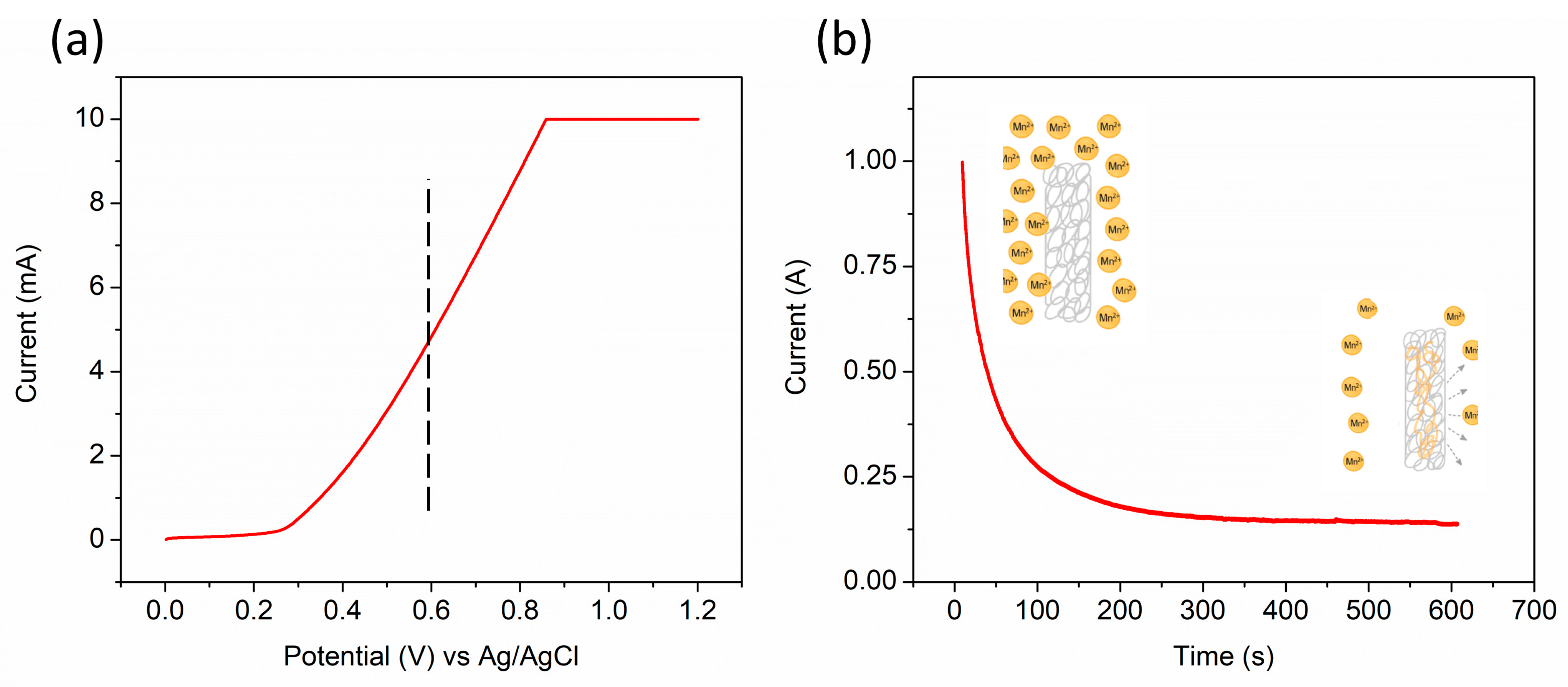
The deposition potential was determined via linear sweep voltammetry (LSV) using a standard three-electrode cell configuration: nickel foam (working), platinum wire (counter), and Ag/AgCl in 3 mol·L−1 KCl (reference). As shown in Figure 1a, the LSV curve exhibited a sharp rise in current near 0.6 V, indicating the onset of MnO2 deposition. Based on this result, a potential of 0.6 V was set as the standard for all subsequent electrodeposition processes.
The MnO2 films were produced via anodic chronoamperometry at a constant potential of 0.6 V vs. Ag/AgCl using a 3 mol·L−1 KCl electrolyte. To evaluate the effect of deposition time, five different durations were investigated: 60, 120, 180, 240, and 300 s. For each condition, three replicate samples were prepared to evaluate reproducibility and mass loading. The deposited mass was determined ex situ by weighing the nickel foam substrate before and after deposition using a high-precision electronic balance (d = 0.01 mg). Prior to each deposition, the electrolyte solution was freshly prepared and purged with nitrogen gas for 2 min to remove dissolved oxygen.
Figure 1b shows a representative chronoamperometric curve at 0.6 V. The decay in current over time is consistent with diffusion-controlled nucleation and growth, described by the Cottrell equation:
i ( t ) = n F A   C j 0 D j π t
where, i is the current (in A); n is the number of electrons transferred; F is the Faraday constant (96,485 C mol−1); A is the electrode area (in cm2); Cj0 is the initial concentration of the species j (in mol cm−3); Dj is the diffusion coefficient (in cm2 s−1) and t is the time (in seconds).
This behavior reflects the transport-limited arrival of Mn2+ ions at the electrode surface. As shown in the schematic in Figure 1b, Mn2+ is oxidized to Mn4+ and deposits as MnO2 according to the reaction:
M n 2 + ( a q ) + 2 H 2 O ( l ) M n O 2 ( s ) + 4 H + ( a q ) + 2 e
Surface morphology and elemental composition of the electrodeposited films were investigated via scanning electron microscopy (SEM) and energy-dispersive X-ray spectroscopy (EDS) using a Zeiss EVO MA10 microscope (Zeiss AG, Oberkochen, Germany). X-ray diffraction (XRD) analysis was performed using a Shimadzu XRD-7000 (Shimadzu Corporation, Kyoto, Japan) diffractometer with Cu Kα radiation (λ = 1.5418 Å), operating with a step size of 0.02° over the 2θ range of 25–100°. For XRD measurements, the deposited material was collected by carefully scraping the surface layer from the nickel foam substrate after successive electrodeposition cycles. Electrochemical characterization was performed via cyclic voltammetry (CV, 10–100 mV·s−1) and galvanostatic charge–discharge (GCD, 2–7 A·g−1) measurements with an Autolab PGSTAT302 potentiostat (Metrohm Autolab, Utrecht, The Netherlands). All experiments were conducted in 1.0 mol·L−1 Na2SO4 utilizing a three-electrode cell (Ni foam/MnO2 working, Pt wire counter, and Ag/AgCl reference electrodes).
To quantify the electrochemical performance, the specific capacitance was then evaluated using both CV and GCD measurements. From the CV data, the gravimetric specific capacitance (Cs) was obtained by integrating the current over the applied potential window and normalizing the result by the mass of the active MnO2 and the voltage range, as expressed in this equation:
C s = I   d V m   .   V
where I represents the current (in A), m is the mass of the active MnO2 material (in g), and ∆V corresponds to the potential window (in V) [18]. For GCD measurements, the gravimetric specific capacitance Cg was determined using the following relationship:
C g = Q   V   .   m = I o   .   t m   .   V
where I0 is the constant current applied (A), ∆t is the discharge time (s), ∆V is the potential window (V), Q is the total discharge charge (C), and m is the mass of active MnO2 material (g) [18]. These equations allowed for comparison between different electrodes and provided insight into the effect of deposition time on capacitive.

3. Results and Discussion

3.1. Morphological and Crystalline Analysis

The morphology, elemental composition and growth evolution of the electrodeposited films were systematically investigated using SEM/EDS and mass loading analysis. Thus, the correlation between deposition time, surface coverage, and compositional changes is summarized in Figure 2.
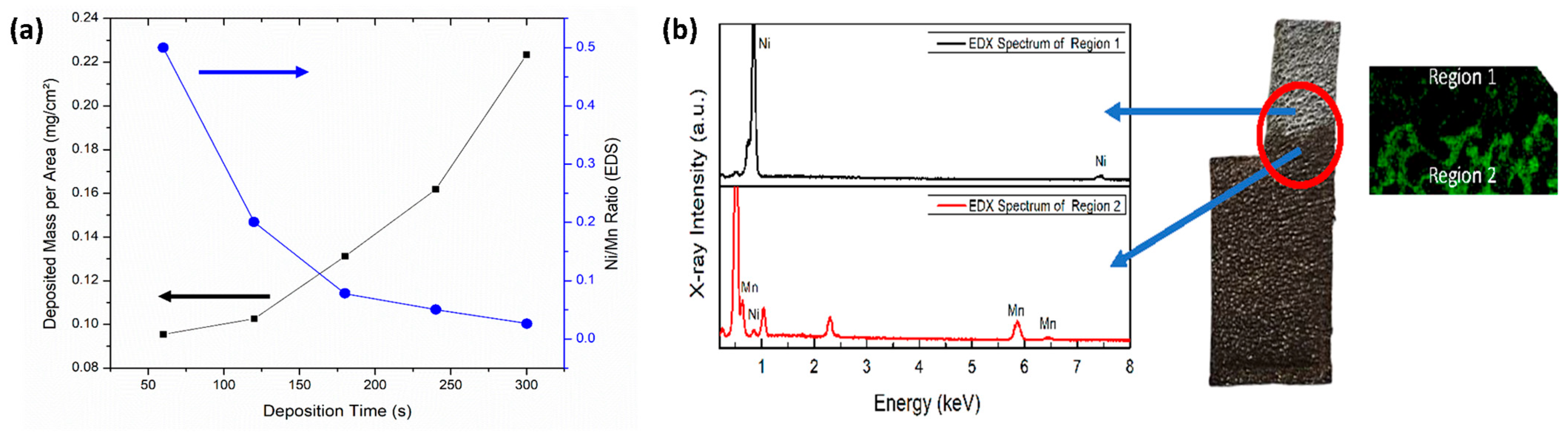
As shown in Figure 2a, the deposited mass per unit area increases progressively with deposition time, indicating continuous growth of the MnO2 layer. This trend is accompanied by a marked decrease in the Ni/Mn signal ratio obtained from EDS analysis, reflecting the gradual coverage of the nickel foam substrate by the deposited material. The inverse relationship between mass loading and Ni/Mn ratio confirms the progressive thickening of the MnO2 film and the corresponding attenuation of the substrate signal.
To further validate the spatial distribution of manganese on the nickel foam substrate surface, EDS measurements were performed on two distinct regions: an area without visible deposition (Region 1) and an area with visibly deposited material (Region 2). Figure 2b shows the corresponding EDS spectra for these two regions. In Region 1, only the Ni signal is detected, indicating the exposed substrate. In contrast, Region 2 shows distinct Mn peaks corresponding to manganese (Mn), confirming the successful deposition of manganese-containing material. The spectrum exhibits Mn Lα at 0.64 keV, and the more intense signals at around 5.9 keV and 6.5 keV, corresponding to Mn Kα and Kβ transitions, respectively, which are characteristic of manganese-containing materials. This direct comparison between deposited and non-deposited regions provides clear evidence of localized film formation on the substrate surface and allows for verification of the deposition process. XRD analysis (Figure S1) indicates that the deposited material predominantly consists of the δ-MnO2 phase [34,35]. The diffraction peaks observed at 2θ ≈ 36.7° and 65.7° are indexed to the (111) and (021) planes of δ-MnO2, respectively. Additionally, the broad background signal suggests the presence of a partially amorphous phase, which is commonly associated with electrodeposited MnO2 and may influence electrochemical performance.
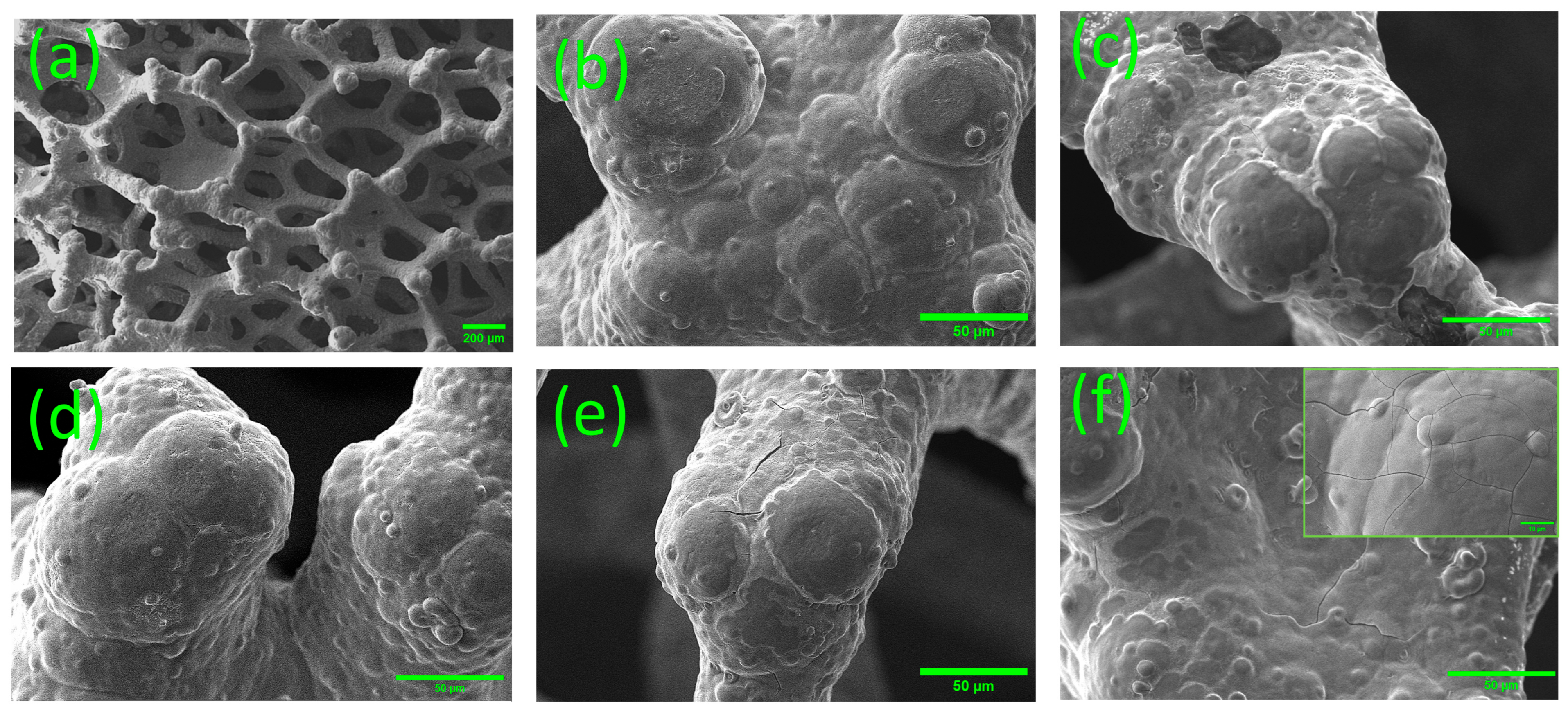
The evolution of surface morphology as a function of deposition time was investigated using SEM, as presented in Figure 3. The pristine nickel foam (Figure 3a) exhibits a highly porous and interconnected three-dimensional architecture, providing a suitable scaffold for MnO2 growth. Figure 3b–f correspond to samples deposited for 60, 120, 180, 240, and 300 s, respectively. As the deposition time increases, the deposited layer progressively thickens. At shorter deposition times, the material exhibits a relatively uniform distribution covering the entire exposed substrate surface. However, when the deposition time exceeds 180 s, the surface morphology becomes increasingly irregular and cracks form, an effect particularly pronounced in the sample deposited for 300 s (Figure 4f), which shows extensive cracking. The increase in deposition time initially promotes higher mass loading of active material, which is generally associated with increased specific capacitance. However, this improvement tends to eventually reach a saturation plateau. Beyond this threshold, further deposition can lead to excessive material accumulation, introducing internal stress and potentially causing surface defects such as cracks. Such defects can impair electrochemical performance by restricting ion transport and increasing interfacial resistance, thereby reducing charge transfer efficiency at the electrode/electrolyte interface. This behavior is consistent with previous studies indicating that excessively thick MnO2 films result in diminished capacitance due to limited electrolyte penetration and inefficient utilization of the active material [25].

3.2. Electrochemical Performance

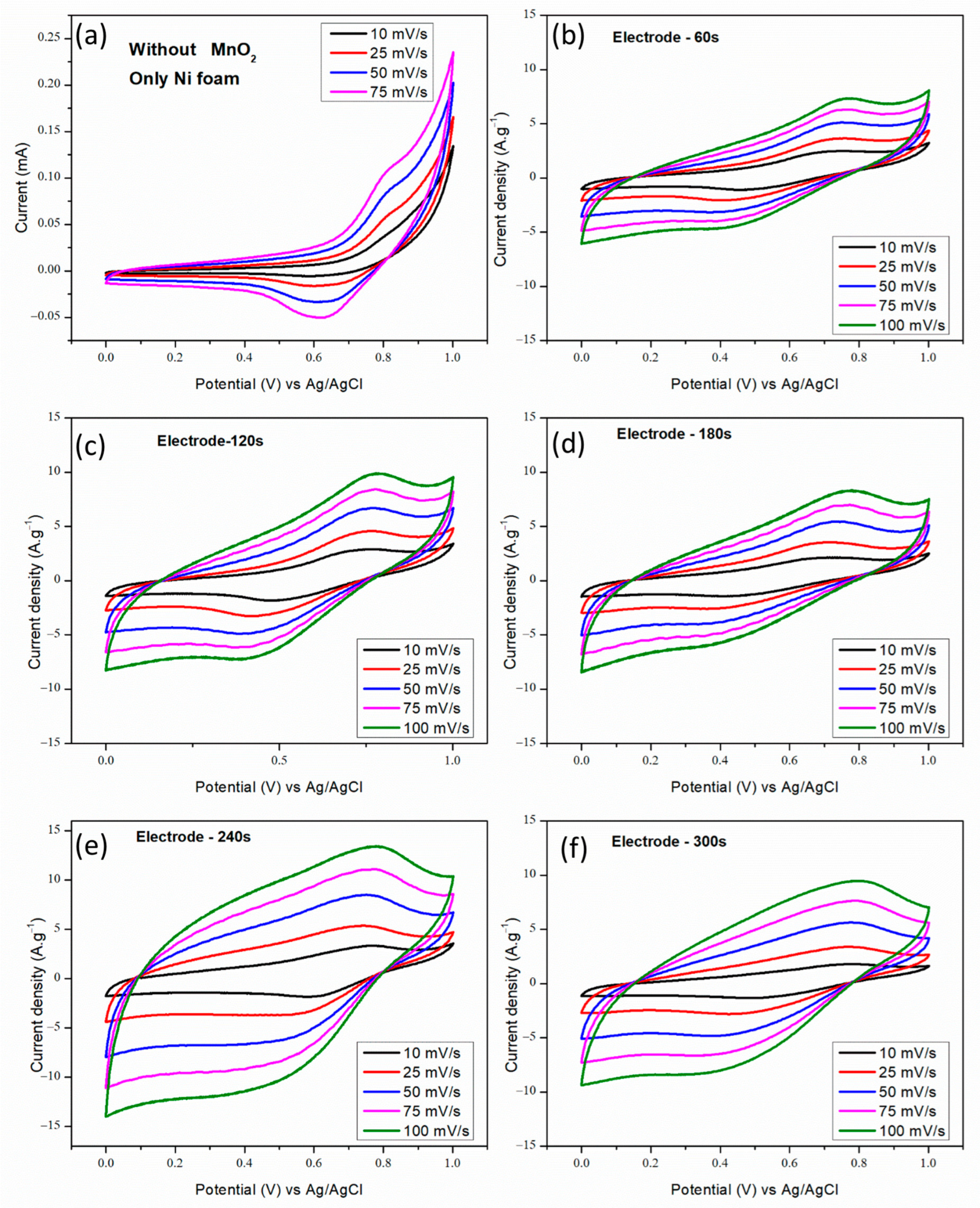
Figure 4 displays the CV responses of the bare nickel foam and MnO2-coated electrodes deposited for 60, 120, 180, 240, and 300 s, recorded at scan rates ranging from 10 to 100 mV·s−1. The bare nickel foam exhibits a negligible current response with no distinct capacitive features, suggesting that no significant charge storage mechanism is present under these conditions. In contrast, all MnO2-coated electrodes display substantially enhanced current densities and broadened CV areas, characteristic of which indicate effective pseudocapacitive behavior arising from the deposited material. The general shape of the CV curves and their evolution with deposition time are consistent with previous reports on MnO2 films grown by electrodeposition over nickel oxide-modified substrates [18].
Thus, the successful formation of electrochemically active MnO2 layers is further supported. In neutral Na2SO4 electrolytes, the charge storage occurs through Na+ insertion/extraction, coupled with electron transfer and a concomitant change in the manganese oxidation state (Mn4+/Mn3+) [16], according to the following reaction:
M n O 2 ( s ) + N a + ( a q ) + e M n O O N a ( s )
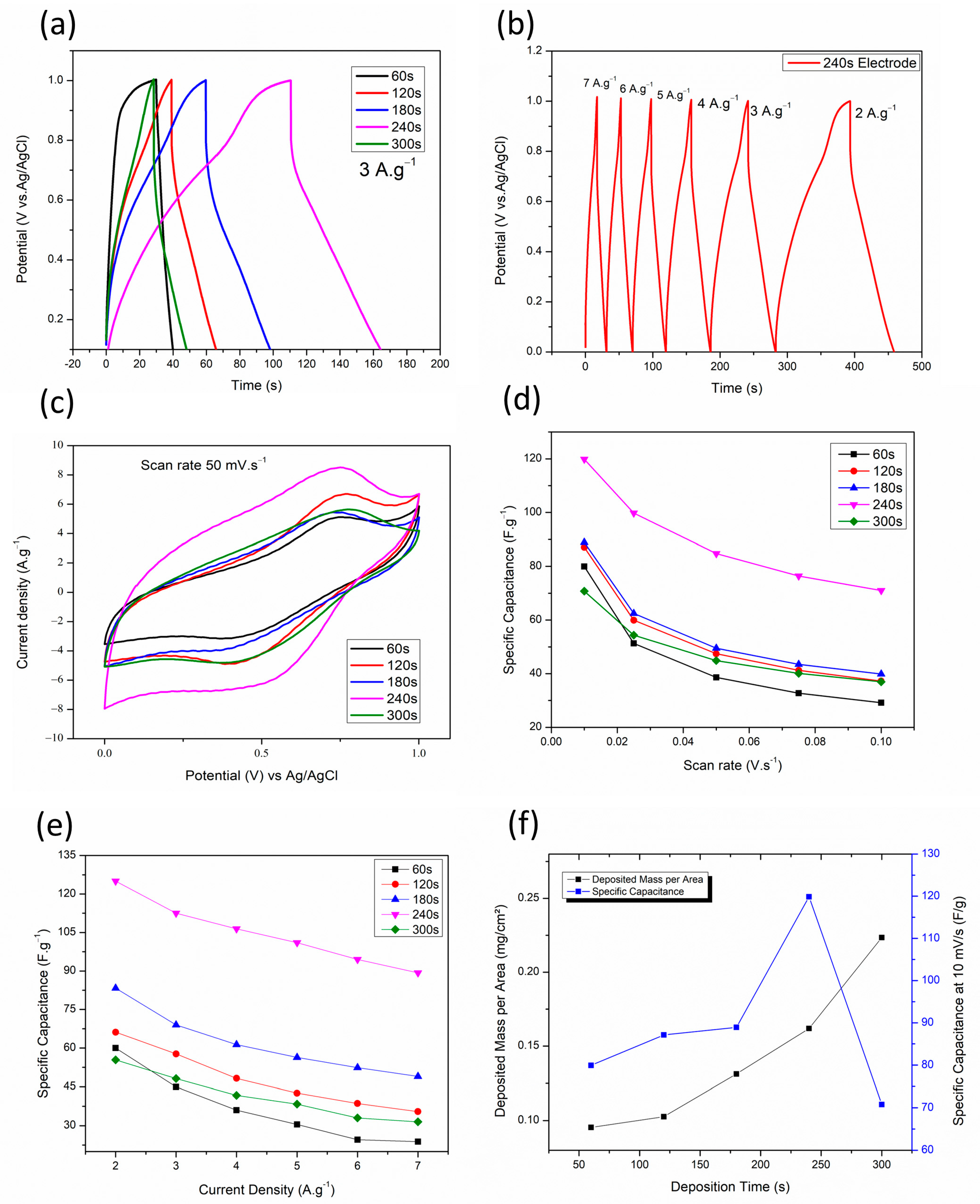
Hence, this mechanism explains the observed electrochemical response. This reversible ion insertion/extraction process contributes to the pseudocapacitive behavior of MnO2 electrodes and is responsible for the redox features observed in the CV curves. Among all samples, the electrode deposited for 240 s consistently displays the largest enclosed CV loop area across all scan rates, indicating enhanced charge storage capability. Notably, this electrode maintains a more symmetric shape even at higher scan rates (100 mV·s−1), suggesting improved rate capability and lower internal resistance compared to the other electrodes. In contrast, the 300 s electrode shows increased distortion and polarization at higher scan rates, reflecting slower ion transport kinetics and higher resistive losses. Hence, this behavior is consistent with SEM observations and aligns with previous findings that thicker MnO2 films can hinder electrolyte diffusion and reduce electrochemical efficiency [18,25]. At shorter deposition times (60 and 120 s), the CV curves exhibit lower current densities and smaller enclosed areas, reflecting insufficient active material loading. However, these samples retain better shape stability at high scan rates, indicating less restricted ion diffusion. These results demonstrate the well-known trade-off between mass loading and ion accessibility in MnO2 electrodes [25,26].
This trend is further confirmed by GCD measurements at a fixed current density of 3 A·g−1 (Figure 5a), where the discharge times increase with deposition time, indicating enhanced charge storage capability. However, this trend does not persist indefinitely; the 300-s sample, while showing longer discharge time, also exhibits signs of inefficiency, likely due to excessive film thickness. The electrode deposited for 240 s exhibits nearly symmetric triangular GCD profiles (Figure 5b), indicating high reversibility and efficient charge–discharge behavior, which is characteristic of pseudocapacitive materials [36].
Figure 5c provides a direct comparison of the CV curves at a fixed scan rate of 50 mV·s−1, clearly illustrating the effect of deposition time on the electrochemical response. A clear increase in the enclosed area is observed as the deposition time increases from 60 to 240 s, indicating enhanced charge storage capability. Notably, the electrode deposited for 240 s exhibits the largest CV area along with a relatively preserved quasi-rectangular shape, suggesting an optimal balance between active material loading and ion transport. In contrast, the 300 s electrode, despite its higher mass loading, shows a slight distortion and reduced effective area, reflecting increased polarization and limitations in ion diffusion. From this perspective, these results reinforce that excessive film growth negatively impacts electrochemical performance, while intermediate deposition times promote more efficient utilization of the electroactive material.
Specific capacitance values were calculated from both CV and GCD measurements and are summarized in Figure 5d,e, respectively. In both cases, the electrode deposited for 240 s consistently exhibits the highest capacitance across the scan rates and current densities tested. Based on GCD results, this electrode achieved specific capacitance values of 125, 112.5, 106.4, 101, 94.5, and 89.3 F·g−1 at current densities of 2, 3, 4, 5, 6, and 7 A·g−1, respectively. Compared to the 60-s electrode, this represents an improvement of approximately 275% at high current density. These results demonstrate that the optimized electrode (240 s) not only performs well within the range of tested conditions, but also compares favorably with values reported in the literature. For instance, Soltani et al. [25] documented a specific capacitance of approximately 80 F·g−1 (at 10 mV·s−1) for MnO2 films electrodeposited for three minutes from a KMnO4-based solution. Clark et al. [35] also reported a value of 95 F·g−1 (at 10 mV·s−1) for MnO2 deposited on nickel foam. In contrast, our electrode, deposited for 240 s in a manganese acetate solution, achieved a value of 120 F·g−1 at 10 mV·s−1, representing a significant enhancement.
This improvement is attributed to better control over film formation, achieved by precise tuning of the deposition time. The 240-s sample exhibited a more uniform and continuous MnO2 coating, improving surface coverage and facilitating charge storage. Additionally, our method offers practical advantages in terms of simplicity and scalability. The use of acetate-based precursors and short deposition times enables reproducible, low- temperature synthesis without the need for post-treatment, making it an accessible route for high-performance MnO2-based SC electrodes.
Under comparable electrodeposition conditions, Zhang et al. [22] reported Mn 2p peaks at approximately 642.1 and 653.9 eV, with a spin–orbit splitting of 11.8 eV, characteristic of Mn4+ species. Additional signals in the Mn 3s and O 1s regions further confirmed the formation of hydrated MnO2·nH2O phase. These oxidation states are in good agreement with the pseudocapacitive behavior observed in the present electrochemical results.
Figure 5f compares the deposited mass per unit area and the specific capacitance at 10 mV/s for each deposition time. Although the deposited mass increases with longer deposition times, the specific capacitance reaches a maximum at 240 s and decreases at 300 s. This decline is likely associated with excessive material accumulation and the presence of cracks observed in SEM images, which hinder ion transport and reduce overall electrochemical performance. This effect is particularly evident at low scan rates and low current densities, where the 60 s electrode exhibited higher performance than the 300 s sample, likely due to improved ion accessibility and more efficient utilization of the active material in the thinner film. Similar behavior has been reported in the literature, where thicker films or prolonged electrodeposition times lead to diminished capacitive performance due to limited ion diffusion and inefficient utilization of the active material [18,25].
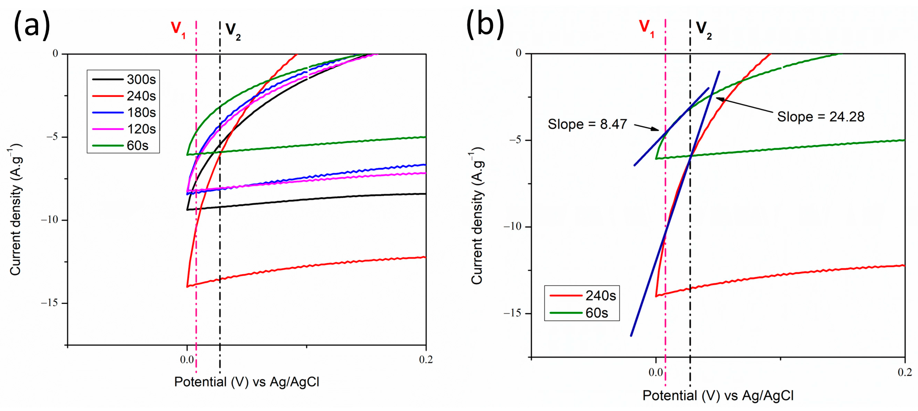
To assess the early-stage capacitive behavior, the current response in the low-potential region (0.00–0.18 V) was examined, where no MnO2 redox activity is expected and charge storage originates mainly from electric double-layer (EDL) formation. To introduce a simple comparative metric of EDL behavior across the electrodes, a fixed voltage interval within this region was selected, and the corresponding slope ΔI/ΔV was used as an indicator of differential capacitance. As shown in Figure 6, the 240-s electrode exhibits a much steeper slope (24.28 A g−1V−1) than the 60-s sample (8.47 A g−1V−1), reflecting a faster capacitive response and greater ion-accessible surface.
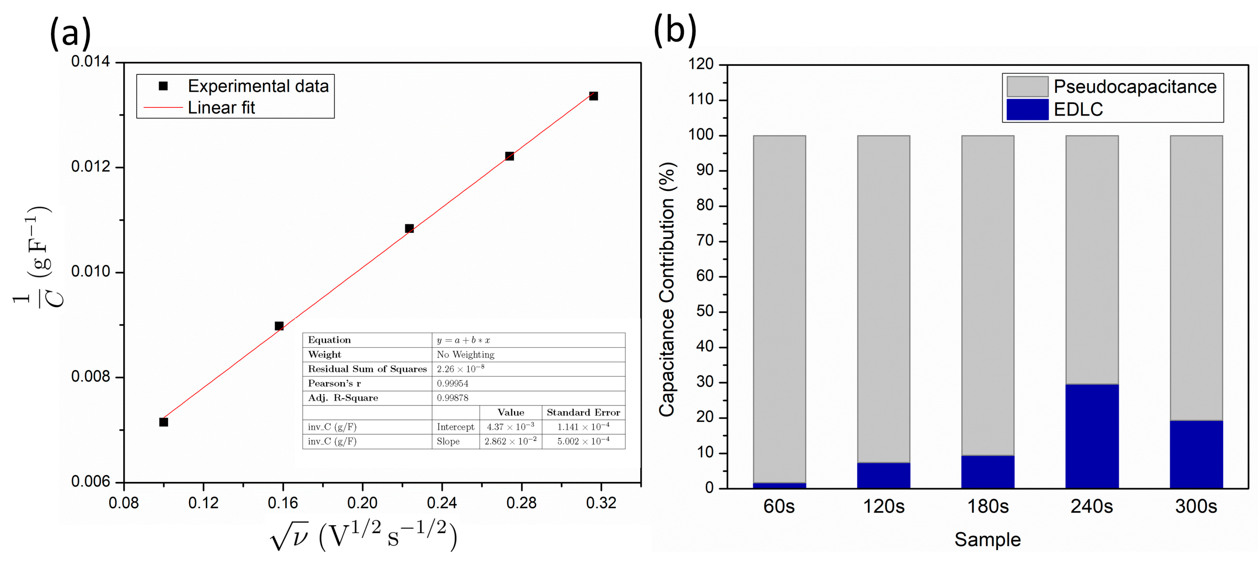
To support this qualitative comparison and quantitatively separate the charge-storage mechanisms, Trasatti’s method was applied. This analysis distinguishes the EDLC contribution from the pseudocapacitive component by examining how the specific capacitance varies with scan rate [36,37]. Since EDLC is fast and largely independent of ν, while pseudocapacitance progressively decreases at higher scan rates owing to ion-diffusion limitations, extrapolating capacitance to the limits of ν → ∞ and ν → 0 enables the isolated determination of each contribution.
According to Trasatti’s relations [37], the inverse of specific capacitance scales linearly with the square root of the scan rate:
1 C = a ν 0.5 + b ,
where the intercept b gives the capacitance at zero scan rate, which represent a condition where both EDLC and pseudocapacitance processes have sufficient time to contribute. Conversely, plotting C as a function of ν −0.5:
1 C = a ν 0.5 + b ,
Extrapolating to ν −0.5 → 0 yields b′ = CEDLC, which represents the capacitance at infinite scan rate, where only the fast EDL mechanism remains active. Hence, the pseudocapacitive portion is then obtained from:
Cpseudo = Ctotal − CEDLC
The linear fit used to extract Ctotal is shown in Figure 7a, while Figure 7b presents the resulting EDLC and pseudocapacitive fractions for each sample. This quantitative decomposition supports the earlier slope-based interpretation and confirms that the 240-s electrode exhibits a markedly higher EDLC contribution compared to the thinner films.

3.3. Effect of Ionic Liquid Additives

To investigate potential strategies for enhancing electrochemical performance, two different ILs, [TEA-PS][BF4] and [BMIM][BF4], were incorporated directly into the aqueous electrodeposition electrolyte containing manganese acetate and Na2SO4. In this approach, MnO2 films were deposited from a solution already containing the IL, allowing its influence on nucleation and film growth to be evaluated in situ. The initial screening was performed by adding each IL at a concentration corresponding to 10% of the estimated mass of Mn2+ ions present in the electrolyte.
The purpose of this preliminary test was to identify whether the incorporation of IL additives could enhance the specific capacitance of the electrodes. At a scan rate of 10 mV·s−1, the addition of [TEA-PS][BF4] led to a decrease of about 11.67% in specific capacitance compared to the unmodified electrode (see Table S1 and Figure S2 in the Supporting Information). In contrast, the use of [BMIM][BF4] resulted in an increase of about 16.7% under the same conditions, indicating a more beneficial effect on electrochemical performance. Based on this initial result, [BMIM][BF4] was selected for further investigation, and its concentrations was systematically varied (1%, 5%, and 10%) to evaluate its impact on capacitance. The aim was to determine the concentration-dependent effect of IL, establishing whether the capacitance follows a monotonic trend or reaches a maximum before diminishing at higher concentrations.
As shown in Table 1, specific capacitance values derived from CV measurements increased with [BMIM][BF4] concentration up to 5%, followed by a slight reduction at 10%. This behavior suggests that while the addition of the ionic liquid improves charge storage, excessive amounts may hinder ion diffusion or negatively affect the film structure. The corresponding plot has been included in the Supplementary Information for visual reference Figure S3.
Notably, the addition of IL caused no significant alterations in the CV profile shapes or the appearance of redox peaks. Hence, this finding suggests that the IL does not directly participate in the electrochemical reactions; instead, it probably affects either the morphology or conductivity of the deposited film (see Figure S4 in the Supporting Information). Additionally, Trasatti’s analysis revealed that the EDLC contribution remained largely unaffected by the ionic liquid, consistently falling within the 25–35% range. The highest specific capacitance (149.83 F·g−1) was recorded for the 5% [BMIM][BF4] modified electrode at 10 mV·s−1, a notable increase compared to the reference value of 119.87 F·g−1 for the unmodified electrode.
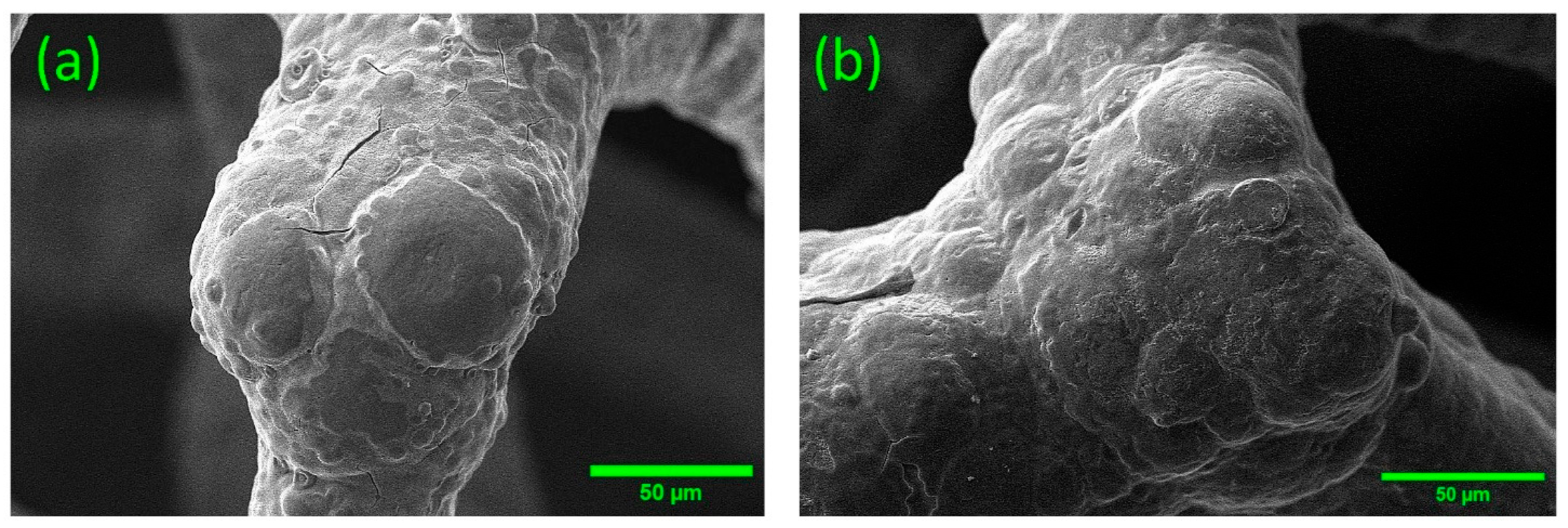
To gain deeper insight into the morphological changes induced by the IL, SEM imaging was performed to directly compare the MnO2 films deposited for 240 s with and without the addition of 5% [BMIM][BF4]. Morphological analysis reveals that the unmodified sample (Figure 8a) exhibits a relatively smooth and dense film, although cracks are present across the surface. In contrast, the IL-modified sample (Figure 8b) presents a more irregular and porous morphology, with lower film density and enhanced surface roughness, suggesting improved accessibility for ion transport and active surface utilization.
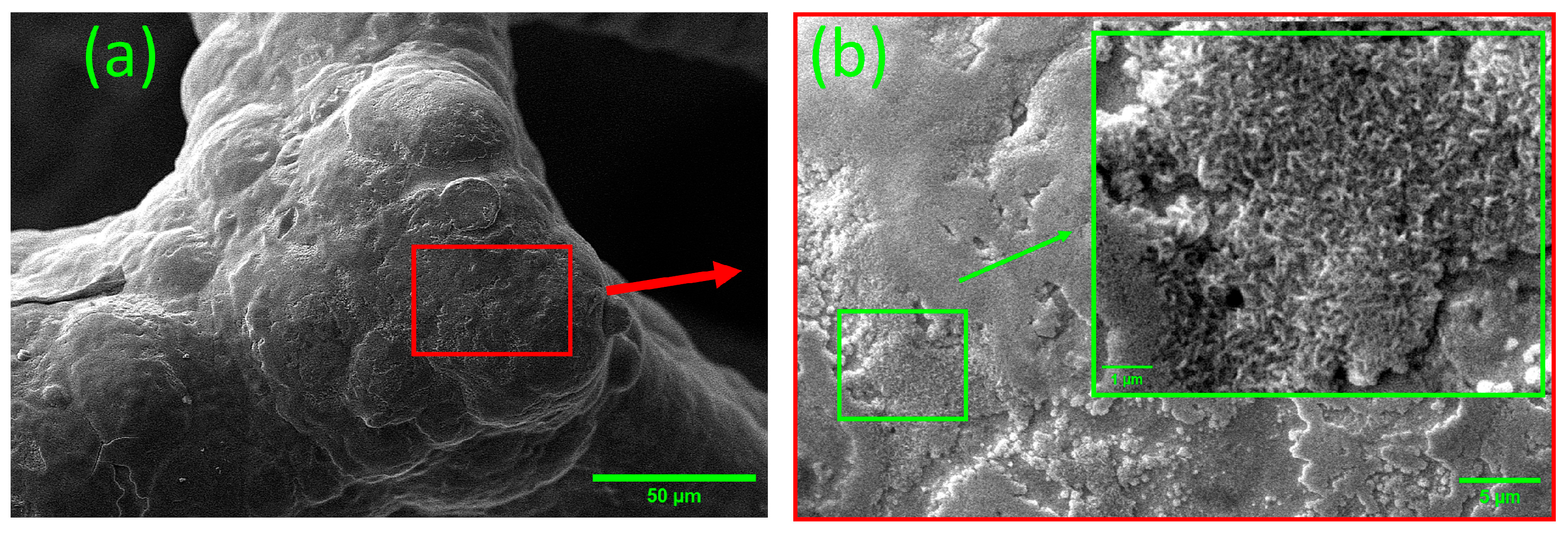
A high-magnification SEM image was acquired to examine the surface architecture in greater detail, a high-magnification SEM image of the 5% [BMIM][BF4]-modified electrode is shown in Figure 9. The enlarged view reveals spike- or flower-like nanostructured formations, likely contributing to the increased electrochemically active area and enhanced capacitive behavior observed for this sample.
Based on these morphological observations, it is proposed that the [BMIM]+ cation acts as a structure-directing agent during electrodeposition. Specifically, the acidic hydrogen at the C2 position of the imidazolium ring may form weak hydrogen-bonding interactions with oxygen atoms on the MnO2 surface, thereby influencing nucleation and growth pathways. Similar hydrogen-bonding interactions between the IL cation and the MnO2 surface have been reported in studies employing ILs as electrolyte [38]. Related interfacial effects have also been observed in ZnO systems, where imidazolium-based ILs promote anisotropic crystal growth through hydrogen-bonding interactions, leading to improved electrochemical performance [39]. Likewise, Bharate et al. [40] demonstrated morphology control in MnO2 films through the use of IL Aliquat HTA-1, which induced a transition from spherical to nanorod structures.
Although [BMIM][BF4] does not directly participate in redox reactions and is not retained in the final electrode, its presence during electrodeposition modifies the nucleation dynamics and growth behavior of MnO2. This promotes the formation of more porous and accessible film architectures, which facilitate ion diffusion and enhance charge storage performance.
Previous studies employing ILs solely as electrolytes have generally reported limited capacitance values; for instance, Lindberg et al. [38] reported only 43 F·g−1 for MnO2 electrodes in EMIM-TFSI systems. In contrast, the strategy adopted in this study, based on incorporation of [BMIM][BF4] directly into the electrodeposition bath, enabled superior morphological control, resulting in significantly enhanced electrochemical performance. Notably, the best-performing electrode, prepared with 5% [BMIM][BF4], delivering a specific capacitance of about 149.83 F·g−1 at 10 mV·s−1, exceeding or matching values reported under comparable conditions. In order to better position the present results, Table 2 compiles representative specific capacitance values reported for MnO2-based electrodes fabricated via various deposition methods.

3.4. Energy and Power Density: Ragone Plot Analysis

To examine in more detail the energy storage capabilities of the MnO2-coated electrodes, the specific energy density (E) and power density (P) were derived from the GCD profiles [22]. These parameters, which are critical for determining the practical applicability of the SCs, were obtained from the following equations:
E = C s ( V ) 2 3.6 × 1 2
P = E t   x   3600
In these expressions, Cs represents the specific capacitance (F·g−1), ∆V denotes the operating potential window (V), and ∆t is the total discharge time (s).
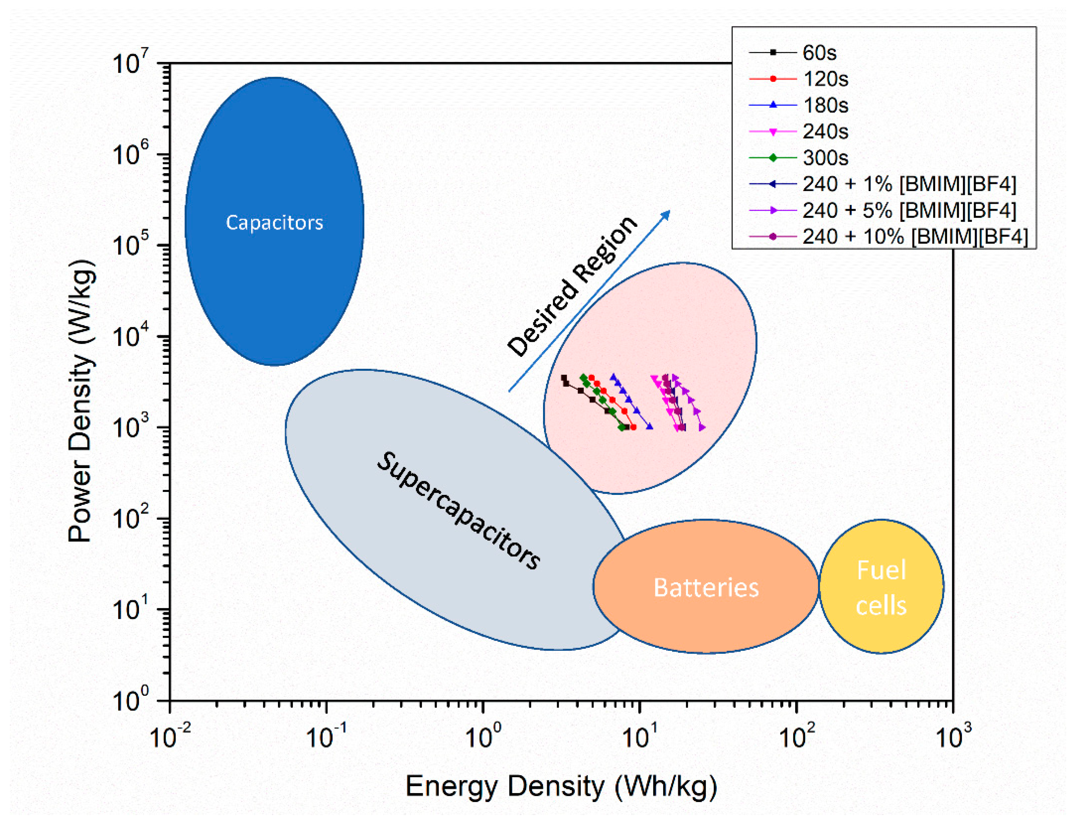
Direct comparison with other energy storage technologies was carried out through the construction of a Ragone plot. Figure 10 presents the resulting plot, where our experimental data for electrodes deposited at 60, 120, 180, 240, and 300 s, as well as those modified with different concentrations of [BMIM][BF4], are overlaid on top of standard performance regions.
The shaded zones representing capacitors, batteries, fuel cells, and conventional SCs, as well as the “Desired Region” for next-generation energy storage, were adapted from the work of Naskar et al. [44]. As shown, all MnO2-coated electrodes fall within the SCs region and exhibit a consistent trend toward improved performance. Notably, the electrode deposited for 240 s and modified with 5% [BMIM][BF4] achieved the top energy density (24.72 Wh·kg−1 at 1000 W·kg−1), outperforming both the unmodified and other IL-modified electrodes.

4. Conclusions

This study demonstrates that the electrochemical responses of MnO2 electrodes can be significantly enhanced through precise control of electrodeposition parameters combined with IL-assisted growth. Our results indicate that the optimal deposition time (240 s) provides a balance between active material loading and ion transport, resulting in improved capacitance and rate capability. Adding [BMIM][BF4] promotes the formation of more porous and accessible nanostructures, leading to a substantial enhancement in electrochemical performance. The best-performing electrode reached a specific capacitance of 149.83 F·g−1 at 10 mV·s−1, representing a significant improvement over the unmodified system. Mechanistically, the IL acts as a structure-directing agent, modulating nucleation and growth processes during electrodeposition and enabling interfacial control over film morphology. These findings highlight the importance of interfacial engineering using ILs as an effective strategy for tailoring MnO2-based electrodes and improving supercapacitor performance. In particular, the novelty of this work resides in the IL-mediated morphology engineering of electrodeposited MnO2 films, where the IL is proposed to influence nucleation and growth processes, leading to optimized nanostructured architectures and enhanced electrochemical behavior. Hence, this strategy establishes a versatile pathway for the rational design of advanced MnO2-based supercapacitor electrodes.

Supplementary Materials

The following supporting information can be downloaded at: https://www.mdpi.com/article/10.3390/surfaces9020045/s1, Figure S1: X-ray diffraction pattern of the MnO2 electrode.; Figure S2. Cyclic voltammetry curves of the MnO2 electrode modified with [TEA-PS][BF4] at scan rates of 10–100 mV·s−1. The curves show a broad pseudocapacitive shape without distinct redox peaks, consistent with non-faradaic charge storage.; Figure S3. Specific capacitance vs. scan rate for electrodes modified with different concentrations of [BMIM][BF4]. The 5% addition resulted in the highest performance, while 10% led to a slight decline.; Figure S4. Cyclic voltammetry curves of electrodes with 0%, 1%, 5%, and 10% [BMIM][BF4] at scan rates of 10–100 mV·s−1. No significant redox peaks are observed, suggesting the IL does not directly participate in electrochemical reactions but influences morphology or conductivity.; Table S1. Specific capacitance (F·g−1) of electrodes deposited for 240 s with and without [TEA-PS][BF4], at different scan rates.

Author Contributions

Conceptualization, H.A.K.M. and M.S.G.; validation, H.A.K.M.; formal analysis, H.A.K.M., J.A.C.S. and M.S.G.; investigation, H.A.K.M.; writing—original draft preparation, H.A.K.M.; writing—review and editing, J.A.C.S., J.C.P., F.d.A.L.P. and M.S.G.; supervision, J.A.C.S., F.d.A.L.P. and M.S.G.; funding acquisition, J.A.C.S., F.d.A.L.P., J.C.P. and M.S.G. All authors have read and agreed to the published version of the manuscript.

Funding

This research was funded by CAPES; CNPq (#306085/2024-0 and 409410/2025-0); Araucaria Foundation; FINEP; and UNILA/PRPPG.

Data Availability Statement

Data will be made available upon request.

Acknowledgments

This work was supported by CAPES; CNPq; Araucaria Foundation; FINEP; and UNILA- PRPPG. The authors also acknowledge the support of the Interdisciplinary Laboratory of Physics Sciences. H.A.K. Moussa gratefully acknowledges CAPES for the Master’s scholarship that supported this research, carried out within the Applied Physics Program at UNILA. The authors used the free version of GPT-4o, (OpenAI) for text editing purposes (e.g., grammar and structure) to finalize the manuscript. The authors reviewed and edited the results and assume full responsibility for the content of this publication.

Conflicts of Interest

The authors declare no conflicts of interest.

Abbreviations

The following abbreviations are used in this manuscript:
CVCyclic voltammetry
EDSEnergy-dispersive X-ray spectroscopy
GCDGalvanostatic charge–discharge
ILIonic liquid
LSVLinear sweep voltammetry
SEMScanning electron microscopy
XRDX-ray diffraction
[BMIM][BF4]1-butyl-3-methylimidazolium tetrafluoroborate
[TEA-PS][BF4]3-triethylammonium-propanesulfonic acid tetrafluoroborate

References

  1. Chatzigeorgiou, N.G.; Theocharides, S.; Makrides, G.; Georghiou, G.E. A Review on Battery Energy Storage Systems: Applications, Developments, and Research Trends of Hybrid Installations in the End-User Sector. J. Energy Storage 2024, 86, 111192. [Google Scholar] [CrossRef]
  2. Dissanayake, K.; Kularatna-Abeywardana, D. A Review of Supercapacitors: Materials, Technology, Challenges, and Renewable Energy Applications. J. Energy Storage 2024, 96, 112563. [Google Scholar] [CrossRef]
  3. Phor, L.; Kumar, A.; Chahal, S. Electrode Materials for Supercapacitors: A Comprehensive Review of Advancements and Performance. J. Energy Storage 2024, 84, 110698. [Google Scholar] [CrossRef]
  4. Khan, H.A.; Tawalbeh, M.; Aljawrneh, B.; Abuwatfa, W.; Al-Othman, A.; Sadeghifar, H.; Olabi, A.G. A Comprehensive Review on Supercapacitors: Their Promise to Flexibility, High Temperature, Materials, Design, and Challenges. Energy 2024, 295, 131043. [Google Scholar] [CrossRef]
  5. Gogotsi, Y.; Penner, R.M. Energy Storage in Nanomaterials–Capacitive, Pseudocapacitive, or Battery-Like? ACS Nano 2018, 12, 2081–2083. [Google Scholar] [CrossRef]
  6. Benavides, D.; Arévalo, P.; Aguado, J.A.; Jurado, F. Experimental Validation of a Novel Power Smoothing Method for On-Grid Photovoltaic Systems Using Supercapacitors. Int. J. Electr. Power Energy Syst. 2023, 149, 109050. [Google Scholar] [CrossRef]
  7. Liang, R.; Du, Y.; Xiao, P.; Cheng, J.; Yuan, S.; Chen, Y.; Yuan, J.; Chen, J. Transition Metal Oxide Electrode Materials for Supercapacitors: A Review of Recent Developments. Nanomaterials 2021, 11, 1248. [Google Scholar] [CrossRef] [PubMed]
  8. Wu, Z.; Zhu, Y.; Ji, X.; Banks, C.E. Transition Metal Oxides as Supercapacitor Materials. In Nanomaterials in Advanced Batteries and Supercapacitors; Springer International Publishing: Cham, Switzerland, 2016; pp. 317–344. [Google Scholar]
  9. Julien, C.M.; Mauger, A. Nanostructured MnO2 as Electrode Materials for Energy Storage. Nanomaterials 2017, 7, 396. [Google Scholar] [CrossRef] [PubMed]
  10. Wu, D.; Xie, X.; Zhang, Y.; Zhang, D.; Du, W.; Zhang, X.; Wang, B. MnO2/Carbon Composites for Supercapacitor: Synthesis and Electrochemical Performance. Front. Mater. 2020, 7, 2. [Google Scholar] [CrossRef]
  11. Pang, M.; Long, G.; Jiang, S.; Ji, Y.; Han, W.; Wang, B.; Liu, X.; Xi, Y. One Pot Low-Temperature Growth of Hierarchical δ-MnO2 Nanosheets on Nickel Foam for Supercapacitor Applications. Electrochim. Acta 2015, 161, 297–304. [Google Scholar] [CrossRef]
  12. Toupin, M.; Brousse, T.; Bélanger, D. Charge Storage Mechanism of MnO2 Electrode Used in Aqueous Electrochemical Capacitor. Chem. Mater. 2004, 16, 3184–3190. [Google Scholar] [CrossRef]
  13. Wang, J.-G.; Kang, F.; Wei, B. Engineering of MnO2-Based Nanocomposites for High-Performance Supercapacitors. Prog. Mater. Sci. 2015, 74, 51–124. [Google Scholar] [CrossRef]
  14. Braga, F.; Casano, G.; Daniels, L.M.; Caffio, M.; Hardwick, L.J. Electrodeposition of Manganese Dioxide Coatings onto Graphene Foam Substrates for Electrochemical Capacitors. Electrochim. Acta 2023, 455, 142433. [Google Scholar] [CrossRef]
  15. Nwanya, A.C.; Iheme, C.W.; Awada, C.; Alshoaibi, A.; Ekwealor, A.B.C.; Ezema, F.I.; Iwuoha, E.I. Phase Evolution of Electrodeposited Manganese Oxide for Supercapacitor Applications. Ionics 2025, 31, 2891–2908. [Google Scholar] [CrossRef]
  16. Phakkhawan, A.; Klangtakai, P.; Chompoosor, A.; Pimanpang, S.; Amornkitbamrung, V. A Comparative Study of MnO2 and Composite MnO2–Ag Nanostructures Prepared by a Hydrothermal Technique on Supercapacitor Applications. J. Mater. Sci. Mater. Electron. 2018, 29, 9406–9417. [Google Scholar] [CrossRef]
  17. Kour, S.; Tanwar, S.; Sharma, A.L. A Review on Challenges to Remedies of MnO2 Based Transition-Metal Oxide, Hydroxide, and Layered Double Hydroxide Composites for Supercapacitor Applications. Mater. Today Commun. 2022, 32, 104033. [Google Scholar] [CrossRef]
  18. Dai, X.; Zhang, M.; Li, J.; Yang, D. Effects of Electrodeposition Time on a Manganese Dioxide Supercapacitor. RSC Adv. 2020, 10, 15860–15869. [Google Scholar] [CrossRef] [PubMed]
  19. Tang, W.; Shan, X.; Li, S.; Liu, H.; Wu, X.; Chen, Y. Sol–Gel Process for the Synthesis of Ultrafine MnO2 Nanowires and Nanorods. Mater. Lett. 2014, 132, 317–321. [Google Scholar] [CrossRef]
  20. Cheng, F.; Zhao, J.; Song, W.; Li, C.; Ma, H.; Chen, J.; Shen, P. Facile Controlled Synthesis of MnO2 Nanostructures of Novel Shapes and Their Application in Batteries. Inorg. Chem. 2006, 45, 2038–2044. [Google Scholar] [CrossRef]
  21. Bai, X.-L.; Gao, Y.-L.; Gao, Z.-Y.; Ma, J.-Y.; Tong, X.-L.; Sun, H.-B.; Wang, J.A. Supercapacitor Performance of 3D-Graphene/MnO2 Foam Synthesized via the Combination of Chemical Vapor Deposition with Hydrothermal Method. Appl. Phys. Lett. 2020, 117, 183901. [Google Scholar] [CrossRef]
  22. Zhang, M.; Chen, Y.; Yang, D.; Li, J. High Performance MnO2 Supercapacitor Material Prepared by Modified Electrodeposition Method with Different Electrodeposition Voltages. J. Energy Storage 2020, 29, 101363. [Google Scholar] [CrossRef]
  23. Walker, P.J.; Mauter, M.S.; Whitacre, J.F. Electrodeposited MnO2 for Pseudocapacitive Deionization: Relating Deposition Condition and Electrode Structure to Performance. Electrochim. Acta 2015, 182, 1008–1018. [Google Scholar] [CrossRef]
  24. Zhang, M.; Yang, D.; Li, J. Supercapacitor Performances of MnO2 and MnO2/Reduced Graphene Oxide Prepared with Various Electrodeposition Time. Vacuum 2020, 178, 109455. [Google Scholar] [CrossRef]
  25. Soltani, H.; Bahiraei, H.; Ghasemi, S.; Hashempour, M. Rate Capability and Electrolyte Concentration: Tuning MnO2 Supercapacitor Electrodes through Electrodeposition Parameters. Heliyon 2025, 11, e41427. [Google Scholar]
  26. Xi, S.; Qian, X.; Cheng, X.; Liu, H.; Shabanzadeh, H.; Dastan, D. One-Step Depositing Method of PAni/MnO2 Composites for Enhanced Supercapacitor Performance. iScience 2025, 28, 111774. [Google Scholar] [CrossRef]
  27. Hassan, S.; Khafagy, A.H.; Usama, D. Anodically Deposited MnO2/Stainless Steel Supercapacitor Electrode at Different Mass Loadings and Different Na2SO4 Electrolyte Concentrations. Am. J. Mater. Sci. 2020, 10, 25–31. [Google Scholar]
  28. Huang, W.; Li, J.; Xu, Y. Nucleation and Growth of Porous MnO2 Coatings Prepared on Nickel Foam and Evaluation of Their Electrochemical Performance. Materials 2018, 11, 716. [Google Scholar] [CrossRef] [PubMed]
  29. Bernardi, J.H.; Arguello, S.A.; de Novais, V.C.; Padilha, J.C.; Parra, R.; Lavayen, V.; Ferrari, J.L.; Sousa Góes, M. Protic Ionic-Liquid Modifies the Microstructure and Photoelectrochemical Performance of Zinc Oxide-Based Photoanodes. Bull. Mater. Sci. 2023, 46, 38. [Google Scholar] [CrossRef]
  30. Xue, J.; Yu, L.; Li, G. Influence of Molecular Structure of Imidazolium Based Ionic Liquids on the Electrochemical Oxidation Performances of Resulting PbO2 Deposits. Int. J. Electrochem. Sci. 2017, 12, 4795–4810. [Google Scholar] [CrossRef]
  31. Omar, I.M.A.; Emran, K.M.; Aziz, M.; Al-Fakih, A.M. A Novel Viewpoint of an Imidazole Derivative Ionic Liquid as an Additive for Cobalt and Nickel Electrodeposition. RSC Adv. 2020, 10, 32113–32126. [Google Scholar] [CrossRef]
  32. Bakar, N.A.A.; Salleh, N.A.; Hamid, N.A.A.; Abdullah, C.A.C.; Rahiman, W.; Basirun, W.J.; Kheawhom, S.; Mohamad, A.A. The Effect Different of Hydrochloric Acid Concentrations on the Cleaning of Ni Foam Substrate: Structural and Morphological Studies. Mater. Today Proc. 2022, 60, 1036–1041. [Google Scholar] [CrossRef]
  33. Arguello, S.A.; Stanhaus, C.; Padilha, J.C.; Cabeça, L.F.; Ferrari, J.L.; Góes, M.S. Use of Ionic Liquid TEA-PS.BF4 as Media Synthesis of ZnO Based on Coprecipitation Method. J. Alloys Compd. 2019, 810, 151835. [Google Scholar] [CrossRef]
  34. Dupont, J.; Consorti, C.S.; Suarez, P.A.Z.; de Souza, R.F. Preparation of 1-Butyl-3-Methyl Imidazolium-Based Room Temperature Ionic Liquids. Org. Synth. 2003, 79, 236. [Google Scholar] [CrossRef]
  35. Clark, M.P.; Qu, W.; Ivey, D.G. Electrodeposition of Nanoscale Manganese Oxide onto Nickel Foam for Energy Storage Applications. ECS Trans. 2015, 64, 57. [Google Scholar] [CrossRef]
  36. Liu, J.; Zhou, Y.; Xie, Z.; Li, Y.; Liu, Y.; Sun, J.; Ma, Y.; Terasaki, O.; Chen, L. Conjugated Copper–Catecholate Framework Electrodes for Efficient Energy Storage. Angew. Chem. Int. Ed. 2020, 59, 1081–1086. [Google Scholar] [CrossRef]
  37. Xue, Y.; Liu, J.; Raza, F.; Zafar, H.; Zhao, H.; Li, R.; Liu, Z. Preparation and Evaluation of Lactoferrin-Modified Curcumin Long-Circulating Nanoliposomes for Hypoxic Brain Injury Therapy. Nanoscale Adv. 2025, 8, 207–223. [Google Scholar] [CrossRef]
  38. Lindberg, S.; Jeschke, S.; Jankowski, P.; Abdelhamid, M.; Brousse, T.; Le Bideau, J.; Johansson, P.; Matic, A. Charge Storage Mechanism of α-MnO2 in Protic and Aprotic Ionic Liquid Electrolytes. J. Power Sources 2020, 460, 228111. [Google Scholar] [CrossRef]
  39. Cole, J.; Syres, K.L. Ionic Liquids on Oxide Surfaces. J. Phys. Condens. Matter 2022, 34, 213002. [Google Scholar] [CrossRef]
  40. Bharate, B.G.; Hande, P.E.; Samui, A.B.; Kulkarni, P.S. Ionic Liquid (IL) Capped MnO2 Nanoparticles as an Electrode Material and IL as Electrolyte for Supercapacitor Application. Renew. Energy 2018, 126, 437–444. [Google Scholar] [CrossRef]
  41. Xi, S.; Zhu, Y.; Yang, Y.; Liu, Y. Direct Synthesis of MnO2 Nanorods on Carbon Cloth as Flexible Supercapacitor Electrode. J. Nanomater. 2017, 2017, 7340961. [Google Scholar] [CrossRef]
  42. Tsai, Y.-C.; Yang, W.-D.; Lee, K.-C.; Huang, C.-M. An Effective Electrodeposition Mode for Porous MnO2/Ni Foam Composite for Asymmetric Supercapacitors. Materials 2016, 9, 246. [Google Scholar] [CrossRef] [PubMed]
  43. Bounor, B.; Seenath, J.S.; Patnaik, S.G.; Bourrier, D.; Tran, C.C.H.; Esvan, J.; Weingarten, L.; Descamps-Mandine, A.; Rochefort, D.; Guay, D.; et al. Low-Cost Micro-Supercapacitors Using Porous Ni/MnO2 Entangled Pillars and Na-Based Ionic Liquids. Energy Storage Mater. 2023, 63, 102986. [Google Scholar] [CrossRef]
  44. Naskar, P.; Chakraborty, P.; Kundu, D.; Maiti, A.; Biswas, B.; Banerjee, A. Envisaging Future Energy Storage Materials for Supercapacitors: An Ensemble of Preliminary Attempts. ChemistrySelect 2021, 6, 1127–1161. [Google Scholar] [CrossRef]
Figure 1. (a) LSV indicating the onset of MnO2 deposition around 0.6 V in a manganese acetate and Na2SO4 aqueous solution. (b) Chronoamperometric current decay at 0.6 V and schematic illustration of the MnO2 deposition mechanism through Mn2+ oxidation.
Surfaces 09 00045 g001
Figure 2. (a) Correlation between deposition time, mass loading, and Ni/Mn ratio. (b) EDS spectra and mapping for two regions on the nickel foam sample. Region 1 shows only Ni signal, while Region 2 reveals Mn peaks, confirming the presence of manganese in the deposited layer.
Surfaces 09 00045 g002
Figure 3. SEM images of nickel foam surface: (a) pristine foam structure; (bf) MnO2 films electrodeposited on nickel foam for 60, 120, 180, 240, and 300 s, respectively. Cracking becomes visible at longer deposition times, especially in (f). The inset in (f) shows a higher-magnification view of the surface cracks.
Surfaces 09 00045 g003
Figure 4. Cyclic voltammetry (CV) curves of (a) bare nickel foam and MnO2 electrodes deposited for (b) 60 s, (c) 120 s, (d) 180 s, (e) 240 s, and (f) 300 s, measured at scan rates of 10, 25, 50, 75, and 100 mV·s−1.
Surfaces 09 00045 g004
Figure 5. Electrochemical performance analysis: (a) GCD curves at 3 A·g−1 for all electrodes; (b) GCD of 240 s electrode at various current densities; (c) CV curves at 50 mV/s for direct comparison; (d) specific capacitance vs. scan rate from CV; (e) specific capacitance vs. current density from GCD; (f) deposited mass per area and specific capacitance vs. deposition time.
Surfaces 09 00045 g005
Figure 6. (a) Low-potential CV region (0.00–0.18 V) for all electrodes. (b) Slope comparison between the 60-s and 240-s samples showing the faster early capacitive rise of the 240-s film.
Surfaces 09 00045 g006
Figure 7. (a) Trasatti plot used to extract the total capacitance Ctotal from the intercept of 1/C vs. ν0.5. (b) EDLC and pseudocapacitive contributions obtained from Trasatti’s method for all electrodes.
Surfaces 09 00045 g007
Figure 8. SEM images of MnO2 films deposited for 240 s: (a) without ionic liquid and (b) with 5% [BMIM][BF4]. The IL-modified film shows improved surface coverage and fewer cracks.
Surfaces 09 00045 g008
Figure 9. (a,b) Zoomed-in SEM image of the 5% [BMIM][BF4]-modified MnO2 film, revealing a fine, nanostructured layer over the nickel foam.
Surfaces 09 00045 g009
Figure 10. Adapted Ragone plot illustrating the positioning of MnO2-based electrodes (with and without [BMIM][BF4]) relative to conventional energy storage technologies. Background zones were adapted from [44]. The data points include electrodes deposited for 60–300 s, and those modified with 1%, 5%, and 10% [BMIM][BF4].
Surfaces 09 00045 g010
Table 1. Specific capacitance (F·g−1) at different scan rates for electrodes prepared with different [BMIM][BF4] concentrations.
[BMIM][BF4] Concentration
Scan Rate (mV s−1)0%1%5%10%
10119.87130.48149.83139.91
2599.79108.14113.94111.33
5084.7593.3296.4492.28
7576.3985.4687.0481.86
10070.9980.1081.3874.84
Table 2. Comparison of specific capacitance values for MnO2-based electrodes reported in the literature and this work.
MethodSubstrateElectrolyteScan Rate (mV·s−1)Cs (F·g−1)Ref.
Anodic (Mn oxide rods)Ni foam0.5 M Na2SO41095[35]
CathodicNi foam1 M KOH1080[25]
In situ redoxCarbon cloth1 M Na2SO4100144[41]
PS + PDNi foam9 M LiNO325125[42]
Pulsed electrodepositionNi foam1 M Na2SO4≤10110[43]
Anodic (5% [BMIM][BF4])Ni foam1 M Na2SO410149.83This work
Anodic (0% [BMIM][BF4])Ni foam1 M Na2SO410119.87This work
Disclaimer/Publisher’s Note: The statements, opinions and data contained in all publications are solely those of the individual author(s) and contributor(s) and not of MDPI and/or the editor(s). MDPI and/or the editor(s) disclaim responsibility for any injury to people or property resulting from any ideas, methods, instructions or products referred to in the content.