Abstract
Polyaryletherketone (PAEK) polymers inherently exhibit low surface activity, leading to poor adhesive bonding performance when using epoxy-based adhesives. In this study, low-temperature plasma surface modification was conducted on carbon fiber-reinforced polyetherketone ketone (CF/PEKK) composites to investigate the influence of plasma treatment parameters on their lap shear strength. Surface characterization was systematically performed using scanning electron microscopy (SEM), X-ray photoelectron spectroscopy (XPS), and contact angle analysis to evaluate morphological, chemical, and wettability changes induced via plasma treatment. The results demonstrated a significant enhancement in lap shear strength after plasma treatment. Optimal bonding performance was achieved at a treatment speed of 10 mm/s and a nozzle-to-substrate distance of 5 mm, yielding a maximum shear strength of 28.28 MPa, a 238% improvement compared to the untreated control. Notably, the failure mode transitioned from interfacial fracture in the untreated sample to a mixed-mode failure dominated by cohesive failure of the adhesive and substrate. Plasma treatment substantially reduced the contact angle of CF/PEKK, indicating improved surface wettability. SEM micrographs revealed an increased micro-porous texture on the treated surface, which enhanced mechanical interlocking between the composite and adhesive. XPS analysis confirmed compositional alterations, specifically elevated oxygen-containing functional groups on the plasma-treated surface. These modifications facilitated stronger chemical bonding between CF/PEKK and the epoxy resin, thereby validating the efficacy of plasma treatment in optimizing surface chemical activity and adhesion performance.
1. Introduction
Carbon fiber-reinforced polymers (CFRPs) have emerged as a pivotal research focus in materials science due to their superior comprehensive properties [1,2]. In recent years, thermoplastic matrix composites (TMCs) have garnered significant attention. Unlike thermosetting composites, thermoplastic resins in TMCs exhibit linear or branched molecular structures, enabling reversible melting through physical softening without chemical crosslinking. This characteristic confers enhanced toughness, elevated damage tolerance, and prolonged fatigue life to TMCs [3,4]. Their environmental sustainability through recyclability has further positioned them as critical functional materials in aerospace applications [5]. Among polyaryletherketones (PAEKs), polyetheretherketone (PEEK) remains the most extensively studied CFRP reinforcement candidate, while polyetherketoneketone (PEKK)—a member of the PAEK family—has emerged as a promising PEEK alternative in recent investigations [5,6,7].
The growing demand for lightweight, high-performance materials in aerospace, automotive, and intelligent manufacturing sectors [8] has intensified research efforts on efficient composite joining technologies [9,10]. Adhesive bonding demonstrates distinct advantages over mechanical fastening methods by eliminating stress concentrations, preserving structural continuity, and reducing component weight [11]. However, the inherent low surface energy of thermoplastic composites, coupled with surface contaminants, significantly compromises their adhesive performance, hindering broader structural applications [12]. Consequently, surface modification prior to bonding has become essential for ensuring reliable joint formation in TMCs.
Current surface treatment methodologies for composites include mechanical abrasion [13], chemical solvents [14], laser irradiation [15], and plasma treatment [16,17,18]. While chemical treatments face environmental concerns and inefficiencies, mechanical and laser methods risk fiber/matrix damage. Plasma surface treatment emerges as an eco-friendly and effective alternative, capable of introducing active functional groups onto composite surfaces through ionization processes without compromising base material properties. This technique effectively enhances surface wettability and adhesion performance, making it particularly suitable for large-area bonding applications [19,20,21,22].
Recent studies have demonstrated the promising potential of plasma treatment in composite surface modification and bonding preparation. Sun et al. [23] investigated the effects of nozzle velocity (5–15 mm/s) and standoff distance (10–20 mm) on the tensile-shear strength of CFRP joints using atmospheric pressure plasma treatment (APPT). Optimal parameters of 5 mm/s nozzle velocity and 18 mm standoff distance achieved a 267% increase in adhesive-bonded CFRP joint strength (from 8.6 MPa to 31.6 MPa). Nandi et al. [24] comparatively assessed surface adhesion properties of CF/PEKK composites using ASTM D3359 Method B tape-bonding tests [25]. The results confirmed superior paint adhesion performance for plasma-treated samples compared to flame and chemical treatments. Li et al. [26] systematically studied the influence of low-pressure oxygen plasma parameters (100–200 W, 1–10 min) on CF/PEEK surface modification. Their findings revealed that 180 W plasma treatment for 5 min yielded optimal surface characteristics and tensile-shear performance. Notably, these studies demonstrated that lower power levels and shorter treatment durations suffice for effective surface modification of thermoplastic composites, contrasting with the extensive research focus on thermosetting materials.
This study focuses on the bonding performance of thermoplastic composites, employing high-strength epoxy resin adhesive to fabricate CF/PEKK composite bonded joints. The surface treatment of CF/PEKK composites was conducted using low-temperature plasma processing equipment. The influence of plasma treatment speed and distance on the adhesive properties was systematically analyzed through tensile shear testing. Post-failure interfacial characterization of the bonded specimens was performed via scanning electron microscopy (SEM) and profilometry. Furthermore, the surface characteristics of plasma-treated composites were comprehensively evaluated, including wettability (via contact angle measurements), surface topography (using scanning electron microscopy and 3D Shape Contour Analyzer, Osaka, Japan), and chemical structure analysis (employing X-ray photoelectron spectroscopy). This multi-faceted investigation aims to elucidate the microscopic mechanisms underlying plasma-induced surface modification, thereby providing theoretical foundations and technical support for the expanded application of thermoplastic composites in structural joining.
2. Materials and Methods
2.1. Experimental Materials
The CF/PEKK laminates used in this study were fabricated through compression molding in the laboratory. Figure 1 presents a schematic diagram of the compression molding apparatus and equipment. The prepreg utilized was APC (PEKK-FC) (Solvay, Paris, France), with AS4D 12K carbon fibers as the reinforcement and PEKK resin as the matrix, constituting 34% of the overall composition (Solvay, Paris, France). The mechanical properties of the prepreg are detailed in Table 1. The laminate was designed with an alternating 0°/90° stacking sequence, consisting of 15 plies, with the outermost fibers oriented at 0°. The total laminate thickness was approximately 2.1 mm.
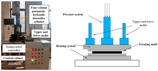
Figure 1.
Compression molding apparatus and its schematic diagram.

Table 1.
Properties of CF/PEKK prepreg.
During the consolidation process of the thermoplastic composite, the prepreg sheets were first cut and arranged according to the predetermined stacking sequence. Ultrasonic spot welding was then employed to tack the plies together, forming a semi-finished thermoplastic composite. Subsequently, the assembly was placed into a compression molding press, where it was subjected to heat and pressure. The molding pressure was set to 0.5 MPa, and the temperature was increased to 380 °C at a heating rate of 3 °C/min, followed by a dwell time of 20 min. The laminate was then naturally cooled to below 50 °C before demolding.
The adhesive used in this article is DP460 two-component epoxy resin adhesive (DP460, Minnesota Mining and Manufacturing Corporation, Saint Paul, MN, USA), which has a high bonding strength and a fast curing speed. The performance parameters of DP460 adhesive are shown in Table 2.
Table 2.
Properties of DP460 adhesive.
2.2. Surface Treatment Equipment
In this study, a pulsed corona discharge low-temperature plasma jet generator (Model: WD-JH-1000 S-V (II), WEIDENG PLASMA, Nanjing, China) was employed. During surface treatment, the substrate was placed on a treatment platform for low-temperature plasma processing. The plasma treatment distance, h, was set to 5, 10, and 15 mm, while the plasma treatment speed, v, was set to 5, 10, 15, 20, and 25 mm/s, respectively. The plasma-treated specimens were designated as Pv–h and subsequently subjected to adhesive bonding tests. To control variables and assess the effectiveness of the plasma treatment, adhesive joints prepared through sandpaper sanding as well as untreated joints were used as control groups.
Pulsed discharge low-temperature plasma equipment primarily generates plasma in a gas medium using a pulsed high-voltage power supply. The gas used in this device is dehumidified air provided via the blower, with a gas flow rate of 6.0 m3/min. The schematic diagram of the low-temperature plasma apparatus and its plasma motion path are shown in Figure 2. Its operating principle can be divided into two key steps:
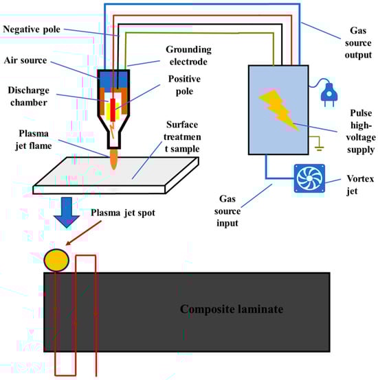
Figure 2.
Schematic diagram of low-temperature plasma device and its plasma motion path.
- (1)
- Generation of low-temperature plasma:
The device employs a pulsed high-voltage power supply that delivers high-voltage energy within a short period, creating a continuous high-frequency, high-voltage electric field in the corona discharge chamber. The high-voltage field between the electrodes causes the gas to break down, forming plasma. The energy provided by the pulsed field ionizes the gas molecules, producing a multitude of high-energy electrons, ions, and free radicals, which constitute the core active species of the low-temperature plasma.
- (2)
- Plasma output:
Once the plasma is generated, a fan blows compressed gas or air into the chamber, directing the low-temperature plasma through a nozzle toward the surface of the material to be treated. Because the pulse discharge duration is brief, excessive heat does not accumulate, keeping the gas temperature relatively low—thus, it is referred to as low-temperature plasma.
Plasma-treated specimens were processed using a computerized motion stage that guided the plasma jet nozzle along the programmed raster path illustrated in Figure 2. For each parameter set, triplicate specimens underwent simultaneous treatment. Owing to the 7 mm diameter plasma jet footprint being insufficient for full-area coverage in a single pass, an optimized raster spacing of 5 mm was implemented. The resultant treated zone (15 mm × 25 mm) exceeded the nominal bonding area dimensions to ensure edge effect mitigation.
The reactive species present in plasma can induce significant modifications to the surface morphology and chemical composition of materials, thereby enhancing their surface adhesion properties.
2.3. Fabrication of Adhesively Bonded Specimens and Mechanical Characterization
Prior to plasma treatment, standardized specimens were subjected to surface pretreatment to eliminate potential artifacts arising from inherent surface conditions. The preparation protocol encompassed the following steps: (1) Samples were immersed in analytical-grade acetone (concentration ≥ 99.5%, from Guangdong, China) for 15 min to thoroughly dissolve and remove organic contaminants, including residual release agents and greases; (2) sequential rinsing with anhydrous ethanol to displace residual solvents, and (3) dehydration in a convection oven at 60 °C for 2 h. To establish experimental controls, two comparative groups were implemented: (i) untreated specimens and (ii) abrasively treated specimens. The abrasive treatment involved the circumferential abrasion of bonding regions using 400-grit silicon carbide sandpaper under constant pressure (0.2 N/mm2), followed by ethanol degreasing and thermal drying identical to the pretreatment sequence.
To mitigate the temporal degradation of plasma-induced surface activation, adhesive bonding was implemented within 30 min post-plasma treatment. Specimen fabrication strictly adhered to GB/T 33334-2016 [27] (Chinese National Standard for Adhesive Shear Strength Testing), with dimensional specifications (100 mm × 25 mm × 2 mm) and overlap geometry (12.5 mm × 25 mm) as schematically detailed in Figure 3. Aluminum alloy reinforcing tabs (6061-T6, thickness: 2 mm) were pre-bonded to both ends to facilitate tensile grip alignment. The adhesive layer thickness was precisely controlled to 0.2 ± 0.03 mm through calibrated stainless-steel spacer wires (Grade 304, Ø 0.2 mm) inserted during fixture assembly. After the joint was bonded, pressure was applied using a fixture, and excess adhesive overflow was removed. As DP460 epoxy resin adhesive is a room-temperature curing adhesive, the bonded sample had to be left to stand at room temperature for 24 h to ensure complete curing of the adhesive before a tensile test was conducted.
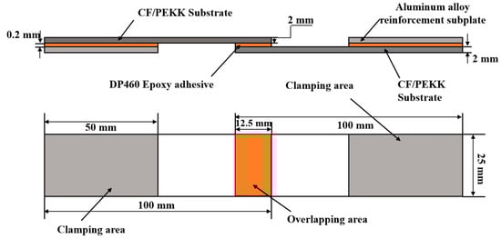
Figure 3.
Schematic diagram of CF/PEKK adhesive joint.
2.4. Experimental Testing and Analysis Methods
2.4.1. Single-Lap Tensile Shear Test
A tensile shear strength evaluation of single-lap joints was conducted in strict compliance with GB/T 33334-2016 [27] (Chinese National Standard for Determination of Shear Strength of Adhesive Bonds). Quasi-static tensile testing was performed using an electromechanical universal testing machine (CMT5150, Sans, Shenzhen, China) equipped with a 100 kN load cell. Displacement-controlled loading was applied at a constant crosshead speed of 2 mm/min until catastrophic joint failure occurred. Peak load values and force-displacement curves were digitally recorded at a sampling frequency of 100 Hz. Triplicate specimens per experimental group were tested, with arithmetic mean values calculated as representative results.
The tensile shear strength (τ) was calculated using the following:
In Equation (1), τ represents the tensile shear strength of the specimen in megapascals (MPa), Fm represents the ultimate load at which the specimen fails in newtons (N), and B and L respectively represent the width and length of the bonded joint in millimeters (mm).
2.4.2. Characterization of Surface Wettability
Surface wettability characterization was performed using a contact angle goniometer (JC2000D2S, Powereach, Shanghai, China) with automated liquid dispensing and image analysis capabilities. For each plasma-treated composite specimen, triplicate measurements were acquired at spatially randomized locations (minimum 5 mm separation) to account for surface heterogeneity, with arithmetic mean values reported. Water and ethylene glycol were selected as probe liquids, with their respective surface tension parameters being tabulated in Table S1. The surface free energy (SFE) of composites was determined via Owens-Wendt-Rabel-Kaelble (OWRK) methodology [28,29].
2.4.3. Scanning Electron Microscopy (SEM) Analysis
The surface micromorphology of untreated and treated samples was observed using scanning electron microscope (GeminiSEM 360, ZEISS, Oberkochen, Germany) at an accelerating voltage of 3 kV, with gold sputtering treatment applied to the composite material surfaces to enhance their conductivity. The magnification of the images taken during SEM testing is 2000× and 10,000×. At the same time, the surface roughness of the samples before and after processing was measured using a 3D profilometer (Bruker ContourGT-X, Karlsruhe, Germany).
2.4.4. X-Ray Photoelectron Spectroscopy (XPS) Analysis
XPS testing was conducted using X-ray photoelectron spectrometer (Thermo Fisher Scientific, Waltham, MA, USA) to analyze and determine the main chemical composition and changes in oxygen-containing functional groups on the surface of the composite material. And Avantage software (version 6.9) was used to perform peak fitting analysis on C1s to determine the content of each functional group.
2.4.5. Fourier Transform Infrared Spectroscopy (FT-IR) Analysis
FT-IR testing was conducted using a Fourier transform infrared spectrometer (Thermo Fisher Scientific Nicolet iS20, Waltham, MA, USA) to investigate the formation of functional groups on the surface of composite materials after different surface treatments. The test wavenumber range was 400–4000 cm−1.
3. Results
3.1. Analysis of Single Overlap Shear Test Results
The tensile shear strength of CF/PEKK adhesive joints under different plasma treatment parameters is shown in Figure 4. The strength of untreated CF/PEKK joints is only 8.35 MPa, which is attributed to the high inertness of the PEKK material surface. After sanding with sandpaper, the strength of the CF/PEKK joints increased to 10.12 MPa, a 21% improvement. Plasma treatment significantly enhanced the strength of the samples. When the plasma treatment distance was 5 mm and the treatment speed was 10 mm/s, the adhesive strength reached its maximum at 28.28 MPa, which is approximately a 238% improvement compared to the untreated joints and a 179% improvement compared to the sandpaper-treated joints.
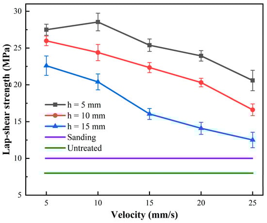
Figure 4.
The variation of CF/PEKK adhesive joint strength with plasma treatment parameters.
For treatment distances of 5 mm, 10 mm, and 15 mm, the tensile strength generally increases as the treatment speed decreases. At the same treatment distance, a lower treatment speed (e.g., 5 mm/s) typically results in higher tensile strength. This may be because a lower treatment speed allows more interaction time between the plasma and the material surface, thus more effectively improving the surface properties. At the same treatment speed, a 5 mm treatment distance generally yields the highest tensile strength, followed by 10 mm, while the 15 mm treatment distance results in the lowest strength. This is likely because the shorter treatment distance concentrates the plasma energy, leading to surface characteristics that are more conducive to bonding.
In summary, plasma treatment significantly improves the strength of CF/PEKK adhesive joints, enhancing the interfacial bonding between CF/PEKK and the adhesive, and fully leveraging the adhesive’s bonding effect. However, the influence of plasma treatment parameters on the adhesive performance of CF/PEKK differs from that of some traditional thermoset epoxy composites [24]. As the treatment distance and treatment speed parameters decrease, the strength of CF/PEKK adhesive joints continuously increases. A shorter treatment distance results in better joint strength, primarily because the PEKK resin in thermoplastic composites has better toughness and impact resistance, allowing it to withstand more plasma impact energy. This also means that improving the surface properties of PEKK requires more energy. Under extreme treatment conditions (a treatment distance of 5 mm and a treatment speed of 5 mm/s), the joint strength slightly decreased, but the reduction was not significant, and the CF/PEKK joints still exhibited high adhesive strength. This also indicates that a smaller treatment parameter does not necessarily result in higher adhesive strength. The active particles in the plasma can also intensify the etching of the CF/PEKK surface, reducing the bonding performance of the surface resin with the adhesive. Therefore, for different types of composites, it is necessary to determine the appropriate treatment parameters in actual production to enhance the effectiveness of plasma treatment.
The lap shear strength, combined with the failure modes of the joints, provides a better assessment of the adhesive performance of the material. The failure modes of composite joints can be classified into interfacial failure, cohesive failure, substrate failure, and mixed failure, where multiple failure modes coexist (the common failure modes of adhesive joints are shown in Figure S1).
The failure modes of CF/PEKK single-lap joints under different plasma treatment parameters are shown in Figure 5. From Figure 5a,b, it can be observed that after no treatment or sanding with sandpaper, the adhesive is mainly concentrated on one side of the adhesive joint, leading to an adhesive interface failure mode. This indicates that the adhesive cannot fully wet the surface of the CF/PEKK composite, resulting in weak interfacial bonding and premature failure at the cohesive interface. As discussed earlier, plasma treatment improves the interfacial bonding of CF/PEKK, significantly increasing the joint strength. As seen in Figure 5c,d, under a treatment distance of 15 mm, when the plasma treatment speed is higher, the failure mode of the joint exhibits adhesive interface failure, with adhesive present at both ends of the joint, resulting in an increase in strength.
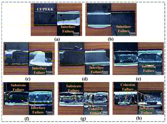
Figure 5.
Failure modes of CF/PEKK adhesive joints with different plasma treatment parameters. (a) Untreated; (b) Sanding; (c) P20–15; (d) P15–15; (e) P10–10; (f) P5–10; (g) P10–5; and (h) P5–5.
When the plasma treatment distance is increased to 10 mm (Figure 5e,f), the CF/PEKK joints exhibit slight substrate failure, along with partial interfacial failure. The active particles in the plasma cause some surface erosion, further enhancing the adhesive joint strength. When the treatment distance is 5 mm (Figure 5g,h), the failure mode of the CF/PEKK joints shows a mixed failure mode of substrate and cohesive failure. In this case, the active particles in the plasma interact fully with the material surface, resulting in significant etching, which maximizes the adhesive’s effect and significantly improves the joint strength. These results demonstrate that plasma treatment significantly enhances the strength of CF/PEKK joints and alters the failure modes of the adhesive joints, fully leveraging the adhesive’s bonding performance.
3.2. Surface Wettability Analysis of CF/PEKK
In surface contact angle measurements of materials, the contact angle can be categorized into hydrophilic and hydrophobic surfaces based on its size. When 0° ≤ θ < 90°, the surface is hydrophilic; when 90°≤ θ < 150°, the surface is hydrophobic; and when 150° ≤ θ < 180°, the surface is superhydrophobic. The size of the contact angle is typically related to the surface energy, which describes the degree of interaction between liquid molecules and the solid surface. Surface energy is usually expressed as surface tension per unit area. The higher the surface energy, the more easily liquid molecules interact with the solid surface, making it easier for the surface to be wetted. A composite material surface with good wettability forms a better bond with the adhesive, which helps improve the material’s surface adhesive properties.
In this study, deionized water and ethylene glycol were used to measure the contact angle on the composite material surface. Deionized water, with its high surface tension and strong polarity, was used to measure the contact angle of water on the material surface, assessing the affinity between the material surface and polar liquids, thus reflecting the surface’s polar characteristics. Ethylene glycol, with a lower surface tension than water and moderate polarity, was used to more comprehensively reflect the wetting behavior of the surface with moderately polar liquids. Combined with deionized water, the surface energy of the material could be calculated.
The contact angles between the surfaces of CF/PEKK treated with different plasma parameters and deionized water are presented in Figure 6. As seen in Figure 6a, the untreated CF/PEKK surface has the highest contact angle with deionized water, at 82.52°, indicating a highly hydrophobic surface with poor wettability. Compared to the untreated surface, the contact angle of CF/PEKK with deionized water significantly decreases after plasma treatment, with the surface gradually transitioning towards a more hydrophilic state, improving its wettability.
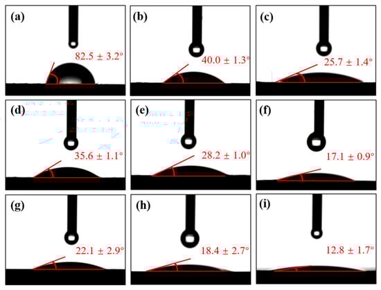
Figure 6.
Contact angle between CF/PEKK surface and deionized water under different plasma treatment parameters. (a) Untreated, (b) P25–15, (c) P10–15, (d) P25–10, (e) P15–10, (f) P5–10, (g) P25–5, (h) P15–5, and (i) P5–5.
Figure 6d–f show the contact angles at a plasma treatment distance of 10 mm under different treatment speeds. It is observed that as the speed increases, the contact angle of the CF/PEKK surface continuously decreases, with the lowest contact angle of 17.13° achieved at a speed of 5 mm/s. From Figure 6c,f,i, it can be observed that under the same plasma treatment distance, the contact angle follows a similar trend. As the plasma treatment distance decreases, the surface contact angle also gradually decreases, with the lowest contact angle of 12.82° achieved at a treatment distance of 5 mm.
The variation trend of contact angles between CF/PEKK surfaces and ethylene glycol, similar to that observed with deionized water, is presented in Figure S2, likewise demonstrating a gradual decrease in ethylene glycol contact angles as plasma treatment speed and distance diminish.
By observing the contact angle changes for both liquids on the CF/PEKK surface, it can be seen that when the plasma treatment parameters are reduced to a certain value, the sensitivity of contact angle changes becomes less pronounced. Additionally, based on the adhesive joint strength, it is clear that the adhesive strength does not increase significantly with the decrease in contact angle. This indicates that plasma treatment also reaches a saturation point for the wettability of the CF/PEKK surface. Beyond this point, further reduction in treatment parameters does not result in significant changes in the material’s surface contact angle, as can be clearly seen from the surface energy data discussed later.
The surface energy composition bar chart of CF/PEKK under different plasma treatment parameters is shown in Figure 7.
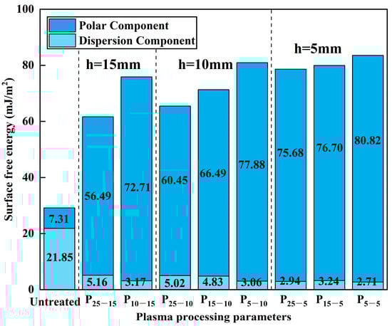
Figure 7.
Surface free energy composition of CF/PEKK under different plasma treatment parameters.
From the surface energy components of CF/PEKK shown in the figure, it can be seen that the untreated CF/PEKK surface is dominated by the dispersion component, with a polar component of 7.31 mJ/m2. As a result, the surface exhibits significant hydrophobicity, which is unfavorable for bonding. After plasma treatment, the surface energy significantly increases, with the dispersion component rapidly decreasing and the polar component’s proportion increasing. The polar component surpasses the dispersion component by a large margin, enhancing the hydrophilicity of the material surface.
After a treatment distance of 5 mm and a treatment speed of 5 mm/s, the CF/PEKK surface energy reaches its maximum, with a total surface energy of 83.53 mJ/m2. The polar component is 80.82 mJ/m2, and the dispersion component is only 2.71 mJ/m2, resulting in a significant improvement in surface wettability and enhanced hydrophilicity. Upon observing the effects of different plasma parameters, it can be seen that as the treatment distance and speed decrease, the overall surface energy of CF/PEKK continuously increases. The dispersion component remains nearly unchanged, while the increase in total surface energy is primarily due to the increase in the polar component. Under different plasma treatment distances, reducing the treatment speed leads to an increase in CF/PEKK total surface energy and a significant rise in the proportion of the polar component. When the treatment distance reaches 5 mm, further reductions in speed result in a smaller increase in surface energy. This is because the CF/PEKK material surface also has a saturation range for wettability, and further increases in plasma treatment parameters do not significantly alter the surface energy of CF/PEKK.
In summary, the increase in the proportion of the polar component in the surface energy is the main reason plasma treatment improves the wettability of CF/PEKK composites, which in turn enhances the bonding effect with the adhesive. However, the wettability of the CF/PEKK composite surface also has a saturation range. When this is combined with the adhesive joint strength data, it is evident that under the condition of a 5 mm treatment distance, the adhesive strength does not significantly increase with further reduction in treatment parameters. This indicates that wettability is not the dominant factor for improving adhesive joint strength.
3.3. Microscopic Morphology Analysis of CF/PEKK Surface
By analyzing the surface microstructure, the specific effects of plasma treatment on the surface state of CF/PEKK composite materials can be more intuitively revealed. This method can observe changes in surface roughness, formation of etched textures, and possible surface defects at the microscale, providing key information about the degree of physical modification of the surface. SEM was used to characterize and analyze the surface morphology of CF/PEKK treated with different plasma parameters, as shown in Figure 8. Among them, Figure 8f,h are the images of P5–10 and P5–5 at high magnification, respectively.
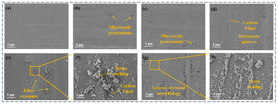
Figure 8.
Microscopic morphology of CF/PEKK surface treated with different plasma parameters (a) Untreated, (b) P10–15, (c) P15–10, (d) P10–10, (e,f) P5–10, (g,h) P5–5.
It can be observed from the figures that the untreated CF/PEKK surface exhibits a relatively smooth resin layer, with fibers and the resin matrix well bonded. When plasma treatment is applied at a speed of 10 mm/s and a treatment distance of 15 mm, small-scale roughness and particles begin to appear on the CF/PEKK surface. In Figure 8c,d, when the treatment distance is further reduced to 10 mm, the surface roughness and particles become more pronounced, and numerous groove-like textures are observed. This indicates an intensified etching effect via the plasma, where the increased roughness improves the bonding effect with the adhesive.
In Figure 8e,f, under a treatment distance of 5 mm at a speed of 10 mm/s, even more groove-like textures are visible, and carbon fibers start to be exposed, accompanied by larger-scale roughness and particles. The magnified images reveal that the resin etching is more significant, which enhances the mechanical interlocking with the adhesive and improves the bonding strength of the thermoplastic composite. As shown in Figure 8g,h, with a further reduction in the treatment distance, the low-temperature plasma treatment exacerbates the ablation of the resin on the CF/PEKK surface, leading to partial resin melting and the more obvious exposure of surface fibers. At this point, the bonding between the PEKK resin and carbon fibers weakens, making the surface fibers prone to peeling during bonding and adversely affecting the adhesive performance.
When a three-dimensional surface profiler is used to observe the three-dimensional surface morphology of the samples before and after treatment, as shown in Figure 9, it can be seen that after low-temperature plasma treatment, the surface roughness of the sample increases. The arithmetic mean height (Sa) before treatment is 1.05 μm, and the surface is relatively flat. After plasma treatment with P10–5, the arithmetic mean height of the sample is 2.54 μm, with many micrometer-scale grooves added, increasing the surface area. Please refer to Table S2 for its relevant parameters. According to the mechanical bonding theory, the increase in roughness is beneficial for increasing the bonding area between the adhesive and the substrate during bonding, which is conducive to improving the bonding strength.
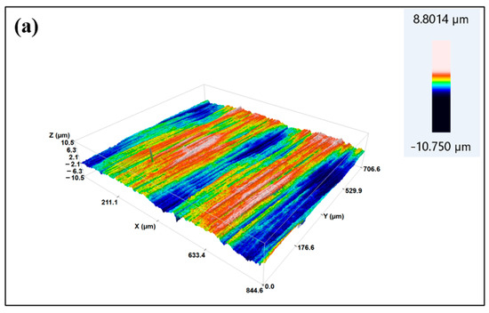
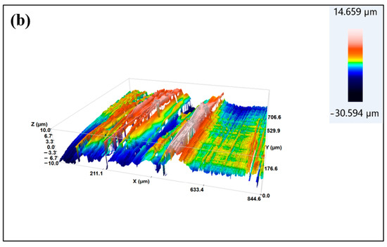
Figure 9.
Three-dimensional morphology of CF/PEKK surface: (a) Untreated; (b) treated with P10–5 plasma.
In summary, plasma treatment significantly increases the surface roughness of CF/PEKK composites and enhances the mechanical interlocking between the adhesive and the CF/PEKK surface, thereby improving the surface bonding performance. However, excessively strong plasma treatment parameters may cause resin melting and fiber damage, which can negatively impact the overall bonding performance.
3.4. Analysis of Surface Chemical Composition of CF/PEKK
Related studies have shown that low-temperature plasma surface treatment involves the action of high-energy active particles in the plasma on the surface of composite materials to undergo chemical reactions, affecting the chemical composition and content of the composite material surface and, thereby improving the surface activity of the composite material.
Therefore, in order to investigate the effect of plasma treatment parameters on the surface chemical structure of CF/PEKK composite materials, XPS was used to test the surface chemical composition, content, and main functional groups of CF/PEKK, and peak fitting was performed on C1s groups. Table 3 lists the surface chemical composition and relative content of CF/PEKK before and after plasma treatment. The XPS full spectrum of CF/PEKK surface before and after plasma treatment is shown in Figure 10.
Table 3.
Chemical composition and relative content of CF/PEKK surface treated with different plasma parameters.
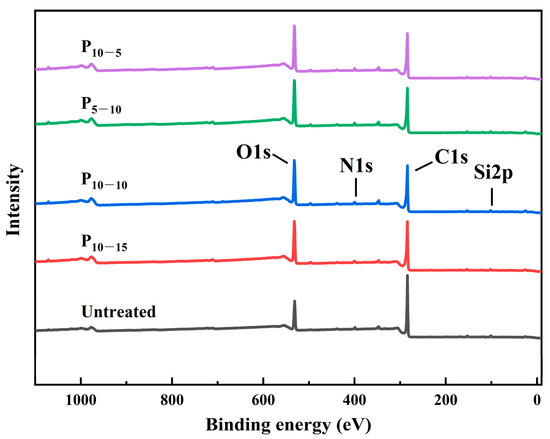
Figure 10.
XPS spectra of CF/PEKK treated with different plasma parameters.
Based on the analysis of the figures and tables, it is evident that the elemental composition of the CF/PEKK composite surface undergoes significant changes before and after plasma treatment. The untreated CF/PEKK surface exhibits a high carbon (C) content and, a low oxygen (O) content, and it contains a small amount of silicon (Si), indicating the presence of a residual release agent on the material surface. After plasma treatment, the contents of C and Si decrease while the O content increases, as the oxygen in the air is ionized to form oxygen-containing polar groups that adsorb onto the CF/PEKK substrate, thereby increasing the surface polarity of the composite. As the plasma treatment speed and distance decrease, the effect of the active species in the plasma becomes more pronounced, resulting in a continuous increase in the O content. The O/C ratio on the CF/PEKK surface rises from 0.26 in the untreated state to 0.48 after P10–5 treatment—an 84.6% increase—indicating that more oxygen-containing groups have been introduced, which enhances the surface wettability. The N/C ratio remains relatively unchanged, suggesting that low-temperature plasma treatment has little effect on the nitrogen-containing groups, while the reduction in Si content further indicates that plasma treatment facilitates the removal of surface contaminants.
Figure 11 shows the peak fitting of C1s on CF/PEKK surface after treatment with different plasma parameters, and Table 4 shows the corresponding peak fitting data of C1s group content on CF/PEKK surface.
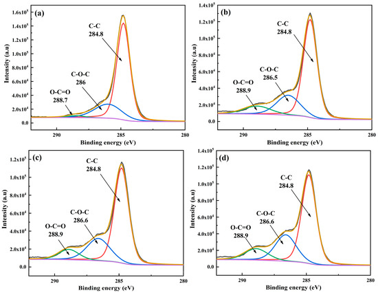
Figure 11.
Peak fitting diagram of C1s on CF/PEKK surface treated with different plasma parameters. (a) Untreated, (b) P10–15, (c) P10–10, (d) P10–5.
Table 4.
Peak fitting data of C1s group content on CF/PEKK surface treated with different plasma parameters.
Based on the figures, the C1s spectra indicate that the primary groups on the CF/PEKK surface are C-C, C-O-C, and O-C=O, located at approximately 284.4 eV, 286 eV, and 288.6 eV, respectively. The untreated CF/PEKK surface exhibits a low content of oxygen-containing groups and a high proportion of nonpolar C-C groups. After plasma treatment, the content of C-O-C polar groups increased, the content of O-C=O polar groups significantly increased, while the content of C-C non-polar groups decreased. This indicates that plasma treatment introduces a substantial number of oxygen-containing groups onto the CF/PEKK composite surface. The oxygen free radicals, which are high-energy active species in the plasma, react with the C-C groups via a crosslinking reaction to form C-O-C structures, which may subsequently oxidize further to yield carboxyl groups (O-C=O). These polar groups grafted onto the CF/PEKK surface enhance its activity, thereby promoting the bonding between the composite and the adhesive. Moreover, as the plasma treatment speed and distance decrease, the oxygen-containing group content on the CF/PEKK surface continues to rise, and the proportion of polar groups increases, which is the primary factor contributing to the improved wettability and enhanced adhesive joint strength of the CF/PEKK composite.
To investigate the effect of plasma treatment on the functional groups of the CF/PEKK surface—and to further analyze and verify changes in chemical bonds and the vibrations of absorption peaks, thereby determining the chemical state of the composite surface and identifying which functional groups are beneficial for interfacial adhesion—the chemical state of the CF/PEKK surface before and after plasma treatment was analyzed using Fourier-transform infrared spectroscopy (FT-IR). Figure 12 shows the FT-IR spectra of the CF/PEKK surface before and after plasma treatment.
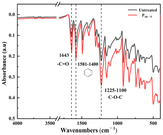
Figure 12.
The FT-IR spectra of the CF/PEKK surface before and after plasma treatment.
The FT-IR spectrum of the plasma-treated CF/PEKK surface shows an increased absorption peak for the -C=O functional group at 1643 cm−1, along with the observation of a C=C stretching vibration peak of the benzene ring at 1581 cm−1. Moreover, the characteristic peak related to the C-O-C functional group at 1225 cm−1 also increases in intensity. The enhanced C-O stretching intensity indicates that the number of oxygen-containing functional groups on the surface has increased, corroborating the XPS findings that plasma treatment produces more C-O groups. This suggests that the active species in the plasma interact with the PEKK surface, and after the cleavage of oxidation bonds on the CF/PEKK surface, these species acquire substantial functionality [30]. Consequently, not only is the polarity of the composite surface increased, but the formation of strong covalent bonds with the adhesive is also facilitated, resulting in improved adhesive performance.
These results demonstrate that the effect of plasma treatment on the PEKK surface primarily manifests in a significant increase in the oxygen content. This is because the high-energy plasma predominantly attacks C–C bonds and graphitized carbon atoms, leading to surface activation and reaction with active plasma species to form oxygen-containing groups. In addition, C–C bonds are more easily broken, allowing oxygen atoms to be introduced to form polar C–O groups, whose proportion steadily increases. This makes the prepreg surface more readily wetted, promoting resin flow between layers during bonding. Meanwhile, the benzene ring structures within the PEKK chains remain relatively stable under plasma treatment, thereby preserving the material’s structural integrity.
4. Conclusions
- Compared to other treatment methods, plasma treatment improves the surface properties of CF/PEKK and enhances its adhesive strength. Among various plasma treatment parameter combinations, the adhesive strength of CF/PEKK reached a maximum of 28.28 MPa when the parameters were set to P10–5 (i.e., a treatment speed of 10 mm/s and a treatment distance of 5 mm). After plasma treatment, the failure mode of the adhesive joints shifted from interfacial failure (as seen in untreated specimens) to a mixed failure mode of cohesive and substrate failure, significantly enhancing the bonding between the adhesive and CF/PEKK.
- After plasma treatment, both the wettability and surface adsorption properties of CF/PEKK are improved. The contact angle of the CF/PEKK surface decreases gradually as the plasma treatment distance and speed are reduced, with a notable increase in both the total surface free energy and its polar component. However, there exists a saturation point for the wettability of the CF/PEKK surface, such that further reductions in treatment parameters do not significantly enhance surface wettability.
- Plasma treatment leaves distinct etching marks on the CF/PEKK surface, making it noticeably rougher and producing numerous groove-like textures. This effectively increases the bonding area of the CF/PEKK surface, improves the mechanical interlocking between the adhesive and the composite, and thereby enhances the adhesive joint strength.
- Following plasma treatment, the surface activity of CF/PEKK increases. The active species in the plasma impact the CF/PEKK surface and form more reactive oxygen-containing functional groups, such as C-O-C and O-C=O. These groups facilitate the formation of stronger chemical bonds with the epoxy resin adhesive, which is a key factor in the enhanced adhesive joint strength of CF/PEKK.
Supplementary Materials
The following supporting information can be downloaded at https://www.mdpi.com/article/10.3390/surfaces8030041/s1: Table S1. Surface energy parameters of water and glycol; Table S2. Surface morphology-related parameters before and after plasma treatment; Figure S1. Failure modes of CF/PEKK adhesive joints. (a) Interface failure, (b) Cohesive failure, (c) Substrate failure; Figure S2. Contact angle between CF/PEKK surface and ethylene glycol under different plasma treatment parameters. (a) Untreated, (b) P25–15, (c) P10–15, (d) P25–10, (e) P15–10, (f) P5–10, (g) P25–5, (h) P15–5, (i) P5–5.
Author Contributions
Writing—review and editing, L.W.; methodology, resources, writing—review and editing, R.W.; writing—original draft, Z.D. All authors have read and agreed to the published version of the manuscript.
Funding
This research received no external funding.
Data Availability Statement
Data are contained within the article.
Conflicts of Interest
The authors declare no conflicts of interest.
References
- Shoaib, M.; Jamshaid, H.; Alshareef, M.; Alharthi, F.A.; Ali, M.; Waqas, M. Exploring the Potential of Alternate Inorganic Fibers for Automotive Composites. Polymers 2022, 14, 4946. [Google Scholar] [CrossRef]
- Sayam, A.; Rahman, A.N.M.M.; Rahman, M.S.; Smriti, S.A.; Ahmed, F.; Rabbi, M.F.; Hossain, M.; Faruque, M.O. A review on carbon fiber-reinforced hierarchical composites: Mechanical performance, manufacturing process, structural applications and allied challenges. Carbon Lett. 2022, 32, 1173–1205. [Google Scholar] [CrossRef] [PubMed]
- Tian, L.; Zhang, P.; Xian, G. Continuous fiber reinforced thermoplastic composite pultrusion with in situ polymerizable methyl methacrylate: A review. Polym Compos. 2023, 44, 4345–4369. [Google Scholar] [CrossRef]
- Adeniran, O.; Cong, W.L.; Oluwabunmi, K. Thermoplastic matrix material influences on the mechanical performance of additively manufactured carbon-fiber-reinforced plastic composites. J. Compos. Mater. 2022, 56, 1391–1405. [Google Scholar] [CrossRef]
- Perez-Martin, H.; Mackenzie, P.; Baidak, A.; Bradaigh, C.M.O.; Ray, D. Crystallisation behaviour and morphological studies of PEKK and carbon fibre/PEKK composites. Compos. Part A Appl. Sci. Manuf. 2022, 159, 106992. [Google Scholar] [CrossRef]
- Perez-Martin, H.; Mackenzie, P.; Baidak, A.; Brádaigh, C.M.Ó.; Ray, D. Crystallinity studies of PEKK and carbon fibre/PEKK composites: A review. Compos. Part B Eng. 2021, 223, 109127. [Google Scholar] [CrossRef]
- Quiroga Cortés, L.; Caussé, N.; Dantras, E.; Lonjon, A.; Lacabanne, C. Morphology and dynamical mechanical properties of poly ether ketone ketone (PEKK) with meta phenyl links. J. Appl. Polym. Sci. 2016, 133, 43396. [Google Scholar] [CrossRef]
- Li, Y.; Xiao, Y.; Yu, L.; Ji, K.; Li, D. A review on the tooling technologies for composites manufacturing of aerospace structures: Materials, structures and processes. Compos. Part A Appl. Sci. Manuf. 2022, 154, 106762. [Google Scholar] [CrossRef]
- Deng, S.; Wu, J.; Dickey, M.D.; Zhao, Q.; Xie, T. Rapid Open-Air Digital Light 3D Printing of Thermoplastic Polymer. Adv. Mater. 2019, 31, 1903970. [Google Scholar] [CrossRef]
- Chen, W.; Li, Y.; Feng, S. Analysis and Prospect of Assembly Technology of Aircraft Composite Fuselage Panel. Aeronaut. Manuf. Technol. 2024, 67, 59–73. [Google Scholar]
- Ramezani, F.; Simões, B.D.; Carbas, R.J.C.; Marques, E.A.S.; da Silva, L.F.M. Developments in Laminate Modification of Adhesively Bonded Composite Joints. Materials. 2023, 16, 568. [Google Scholar] [CrossRef] [PubMed]
- Kantharaju, S.; Vinodhini, J.; M, G.; Bhowmik, S. An investigation to enhance the mechanical property of high-performance thermoplastic composite through different plasma treatment. Polym Compos. 2023, 44, 178–189. [Google Scholar] [CrossRef]
- Yang, G.; Yang, T.; Yuan, W.; Du, Y. The influence of surface treatment on the tensile properties of carbon fiber-reinforced epoxy composites-bonded joints. Compos. Part B Eng. 2019, 160, 446–456. [Google Scholar] [CrossRef]
- del Olmo, R.; Tiringer, U.; Milosev, I.; Visser, P.; Arrabal, R.; Matykina, E.; Mol, J.M.C. Hybrid sol-gel coatings applied on anodized AA2024-T3 for active corrosion protection. Surf. Coat. Technol. 2021, 419, 127251. [Google Scholar] [CrossRef]
- Choi, B.K.; Kang, C.S.; Yoo, M.H.; Seo, M.K. Effect of Processing Parameters on Bonding Performance of a Carbon Fiber/Polyetheretherketone Thermoplastic Composite Prepared by Induction Welding. Materials 2023, 16, 3954. [Google Scholar] [CrossRef]
- Pitto, M.; Fiedler, H.; Kim, N.K.; Verbeek, C.J.R.; Allen, T.D.; Bickerton, S. Carbon fibre surface modification by plasma for enhanced polymeric composite performance: A review. Compos. Part A Appl. Sci. Manuf. 2024, 180, 108087. [Google Scholar] [CrossRef]
- Bertin, M.; Leitao, E.M.; Bickerton, S.; Verbeek, C.J.R. A review of polymer surface modification by cold plasmas toward bulk functionalization. Plasma Process. Polym. 2024, 21, 2300208. [Google Scholar] [CrossRef]
- Avci, R.; Cakici, U.G.; Cetinkaya, B.; Oktem, M.F. Effect of atmospheric plasma treatment and wet blast on adhesion characteristics of carbon fiber reinforced LM-PAEK thermoplastic composites. Compos. Part B Eng. 2024, 278, 111394. [Google Scholar] [CrossRef]
- Zhao, Y.; Zhao, G.; Li, M.; Ge, Y.; Xu, J. The Effect of Surface Treatment on the Resistance Welding Technology for Carbon Fiber/Epoxy Resin Composites. Appl. Compos. Mater. 2024, 31, 201–221. [Google Scholar] [CrossRef]
- Paranjpe, N.; Uddin, M.N.; Rahman, A.S.; Asmatulu, R. Effects of Surface Treatment on Adhesive Performance of Composite-to-Composite and Composite-to-Metal Joints. Processes 2024, 12, 2623. [Google Scholar] [CrossRef]
- Guo, W.; Lim, Y.C.; Ong, C.H.; Kumar, A.S. Atmospheric pressure plasma application on the adhesive bonding improvement of CFRP via surface configuration comparison. Polym. Compos. 2024, 45, 1461–1471. [Google Scholar] [CrossRef]
- Zhang, X.; Ye, W.; Long, X.; Cao, H.; Sun, Q.; Ma, Y.; Wang, Z. Interfacial bonding properties of ultra-high molecular weight polyethylene fabric/thermoplastic polyurethane composites. J. Text. Res. 2023, 44, 143–150. [Google Scholar]
- Sun, C.; Min, J.; Lin, J.; Wan, H. Effect of Atmospheric Pressure Plasma Treatment on Adhesive Bonding of Carbon Fiber Reinforced Polymer. Polymers 2019, 11, 139. [Google Scholar] [CrossRef]
- Nandi, A.; Kumar Biswal, A.; Nguyen, A.; Nordyke, L.; Behling, E.; Foulds, T.; Schultz, K.; Vashisth, A. Comparative study of surface preparation for paint adhesion on CF-PEKK composites: Plasma, Chemical, and Flame treatment. Appl. Surf. Sci. 2024, 669, 160533. [Google Scholar] [CrossRef]
- ASTM D3359-23; Standard Test Methods for Measuring Adhesion by Tape Test. American Society for Testing and Materials: West Conshohocken, PA, USA, 2023.
- Li, C.; Zhang, J.; Sun, F.; Liu, G.; Blackman, B.R.K.; Si, Y.; Yu, J. Effect of low-pressure plasma processing parameters on the surface topography of a CF/PEEK composite for adhesive bonding. Polym. Compos. 2024, 45, 11212–11222. [Google Scholar] [CrossRef]
- GB/T 33334-2016; Test Method for Strength Properties of Adhesives in Shear by Tension Loading of Single-Lap-Joint Laminated Assemblies (Composite and Composite). China Standard Press: Beijing, China, 2016.
- Wen, L.; Xu, X.; Qin, L. Effect of Low-Temperature Plasma Surface Treatment on Bonding Properties of Single-Lap Joint of Thermosetting Composites. Polymers 2023, 15, 1631. [Google Scholar] [CrossRef] [PubMed]
- Wen, L.; Wang, R.; Xu, E. Optimization and Mechanism Study of Bonding Properties of CFRP/Al7075 Single-Lap Joints by Low-Temperature Plasma Surface Treatment. Coatings 2024, 14, 541. [Google Scholar] [CrossRef]
- Shin, Y.; Qiao, Y.; Canfield, N.; Yu, Z.; Meyer, H.M., III.; Merkel, D.R.; Nickerson, E.K.; Kanbargi, N.S.; Ortiz, A.; Naskar, A.K.; et al. Significant slowdown of plasma-optimized surface energy deactivation by vacuum sealing for efficient adhesive bonding. Compos. Part B Eng. 2022, 240, 110001. [Google Scholar] [CrossRef]
Disclaimer/Publisher’s Note: The statements, opinions and data contained in all publications are solely those of the individual author(s) and contributor(s) and not of MDPI and/or the editor(s). MDPI and/or the editor(s) disclaim responsibility for any injury to people or property resulting from any ideas, methods, instructions or products referred to in the content. |
© 2025 by the authors. Licensee MDPI, Basel, Switzerland. This article is an open access article distributed under the terms and conditions of the Creative Commons Attribution (CC BY) license (https://creativecommons.org/licenses/by/4.0/).